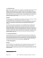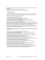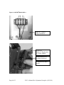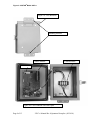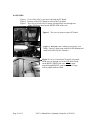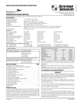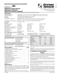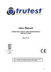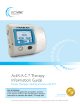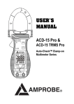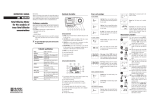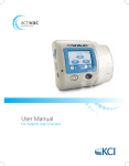
1
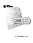
Carbon Monoxide (CO)
Detecting Ventilation
Fan Controller
Model COSTAR® 24VC-e
Single Relay
Part No. 905-0000-09
Replacement Sensor Module is
Part Number 905-0001-09
1. INTRODUCTION
Your COSTAR® 24VC-e carbon monoxide detecting ventilation fan controller is designed for use
whereventilation fans are needed to prevent dangerous accumulations of carbon monoxide (CO)
from engine exhaust or combustion appliances. The COSTAR® 24VC-e lowers operating costs by
activating the fan only when required to maintain good air quality while enhancing safety by
alarming if dangerous CO conditions are detected. The COSTAR® 24VC-e features an
electrochemical sensor and a microcomputer-based CO detection circuit. The microcomputer
provides overall supervisory control, measures CO level and calculates CO dose. It also self-tests
the internal electronic circuit and signals a fault warning if a malfunction is detected. The CO
sensing element is replaceable every 3 years. Each individual sensor is factory calibrated; no
field adjustments are necessary or possible except for sensor replacement. A signal indicating
sensor replacement is given when necessary.
There is a 12 Year Main Printed Circuit Board (PCB) end-of-life. At that time the customer will
need to replace the PCB in the case. Sixty days prior to end of life, the unit will beep 2 short
beeps every 15 seconds until replaced. After warning for 60 days, the unit will go into fault with
all LED’s flashing (fans will run continuously).
In-Field carbon monoxide testing capability is required. When the test button is pressed, the unit
goes into an accelerated test mode for about 3 minutes and will beep 3 short 100 millisecond
beeps once before going into the test mode. In this mode, there are no delays associated with
the fan or siren. This allows someone to spray some CO on the sensor and see how it responds.
A detailed procedure for the testing method is attached as Appendix A – (In-Field CO Testing
QCP-190.10.5110). After testing, the unit returns to normal operation and will beep 2 short 100
millisecond beeps before returning to normal operation.
2. IMPORTANT!
When installing the COSTAR®24VC-e:
A. Read these instructions carefully. Failure to follow them could damage the COSTAR ® 24VC-e
or cause a hazardous condition.
B. Check the ratings given in the following instructions, in Table 1A-COSTAR® 24VC-e Product
Features, and on the COSTAR® 24VC-e to make sure the COSTAR® 24VC-e is suitable for your
application.
C. Installer must be trained and experienced in control systems.
D. After installation is complete, check out the operation of your COSTAR® 24VC-e as instructed
in Section 7, Power-Up and Test.
Page 1 of 13
24VC-e Manual Rev.0 Quantum Group Inc. (02/14/14)
3. SYSTEM OPERATION
Figure 1 shows a typical COSTAR® 24VC-e installation. The COSTAR® 24VC-e provides a single
pole dry contact relay for fan control. For maximum safety, connect the COSTAR ® 24VC-e
directly to a normally closed (N.C.) fan contactor. In clean air, the relay contact K1-K2 is closed
and the fans are OFF. Under ambient temperature, when a CO level of greater than 25 parts per
million (PPM) is detected, or if a circuit failure occurs, the relay contact K1-K2 is opened and the
fans are turned ON. Once turned ON, the fan will run until the COSTAR ® 24VC-e senses the CO
level has fallen below 25 PPM, or the circuit fault is corrected. To eliminate short cycling,
minimum fan cycle time is 2.5 minutes.
WARNING
For proper operation of the COSTAR® 24VC-e ventilation fan controller, the ventilation fan MUST
be wired such that the fan is OFF when the relay contact K1-K2 is closed.
The COSTAR® 24VC has three indicator lights on the front panel. A flashing green light indicates
normal, power-on operation. A yellow light turns on when the COSTAR® 24VC-e calls for fan
operation. A red panel light and a built-in audible alarm signal potentially dangerous CO
conditions.
For protection from long-term overexposure to CO, the COSTAR® 24VC-e calculates the CO
dose over approximately the preceding 8 hours. Using the National Institute of Occupational
Safety & Health (NIOSH) 1, guideline an individual’s exposure limit is not to exceed a TimeWeighed Average (TWA) of 35 PPM for an 8-hour workday. At 35 PPM CO for 8 hours equates to
a dosage of 280 PPM-Hours. Under ambient to high temperature, if a CO dose of 280 PPM- is
accumulated over that 8 hour period, the COSTAR® 24VC-e alarms with a loud beeping tone and
flashing of the red panel light. The high dose alarm will reset automatically in clean air. However,
the dose calculation continues after the reset and the alarm will reactivate should high dose
conditions continue or re-occur.
4. LOCATION AND MOUNTING
Your COSTAR® 24VC-e will monitor up to 10,000 square feet of open area. If the shape of the
area to be monitored is unusual or if the airflow is not uniform, then the area monitored by each
unit should be appropriately reduced. Select a mounting location in an area of heavy traffic flow,
away from drafts, and where the vent holes in the enclosure will not be blocked. Mount the unit at
a convenient height, typically about 5 feet from the floor. External mounting feet are provided.
Use 6 screws to secure the unit to its mounting surface. (See Figure 3A)
5. POWER REQUIREMENTS
WARNING
A. Your COSTAR® 24VC-e is designed for use with a 24 VAC power supply and a 24 VAC relay
(control circuit) voltage. Use of higher voltages can damage your unit or cause improper
operation or a hazardous condition. Control relay contact K1-K2 is rated at 5 amps, 24 VAC. If a
greater load capacity or higher voltage is required, use an intermediate relay between the control
relay and the load.
1
NIOSH 6604 2003-154
Page 2 of 13
24VC-e Manual Rev.0 Quantum Group Inc. (02/14/14)
B. Both the power circuit and the control circuit of the COSTAR ® 24VC-e must be wired with 18
AWG or heavier copper wire. The power requirement of each COSTAR® 24VC-e unit is
approximately 0.1 amps at 24 VAC. Comply with local codes and standards when installing the
COSTAR® 24VC-e.
C. If you have questions call 800-432-5599 and email [email protected].
6. WIRING
A. Open the enclosure. The COSTAR® 24VC-e is mounted on the inside of the enclosure.(See
Figure 2)
B. Terminal block for electrical connections is mounted on a plate in the back of the enclosure
(see Figure 2A).
C. WARNING: To prevent fire and shock, be sure to turn OFF power to the fan control system
and turn OFF power to the 24 VAC supply for the COSTAR® 24VC before wiring and connecting
the COSTAR® 24VC-e.
D. Connect 24 VAC supply to terminals T1 and T2 of the terminal block. Each COSTAR ® 24VC-e
unit requires about 2 watts of power.
E. Connect relay (control) contact K1-K2 in series with the coil of the ventilation fan contactor or
the intermediate relay.
WARNING: For proper operation, the COSTAR® 24VC-e MUST be wired such that the fans are
OFF when relay contact K1-K2 is closed.
F. Verify correct installation of the CO sensor module (See Figure 2B).
7. POWER-UP AND TEST
A. Close and latch enclosure door.
B. Turn ON 24 VAC power to COSTAR® 24VC-e.
C. Within 2 seconds, the audible alarm should give no more than two beeps and green light on
the front panel should be flashing. After a further delay of about 1 second, the yellow light
should turn ON solid. The yellow light may turn OFF after about 5 minutes. This sequence
indicates proper operation of the COSTAR® 24VC-e. If no lights are ON or a different light
sequence is observed follow the instructions in Section 9, Troubleshooting.
D. Turn OFF power to COSTAR® 24VC-e. Turn ON power to fan control system, then turn ON
power to COSTAR® 24VC-e. After a delay of about 2 seconds, the audible alarm should give no
more than two beeps and the green light on the front panel should begin flashing. After a further
delay of about 1 second, the yellow light should turn ON. The fan should turn ON when the yellow
light turns ON. The fan should remain ON as long as the yellow light remains ON (minimum about
5 minutes each time the COSTAR® 24VC-e is powered up). If no lights are ON, if a different light
sequence is observed or if the fan does not turn ON, follow the instructions in Section 9,
Troubleshooting.
E. If power-up tests are satisfactory, secure the enclosure. Your COSTAR® 24VC-e is ready for
normal operation (See Figure 1)
8. SENSOR REPLACEMENT
The COSTAR® 24VC-e CO sensor has a lifetime of 3.0 years. About 60 days before the end of
life, the COSTAR® 24VC-e will begin to beep once every 15 seconds. If the sensor is not replaced
within 60 days, the COSTAR® 24VC-e will turn the fan ON and goes into a fault mode. It cannot
be reset until the sensor is replaced.
A. Purchase a replacement CO sensor module from your supplier or the Quantum Group Inc.
B. Turn OFF the power to COSTAR® 24VC-e and the fan control system.
Page 3 of 13
24VC-e Manual Rev.0 Quantum Group Inc. (02/14/14)
C. Open enclosure and remove old sensor module by pulling it straight out of its socket (See
Figure 2B).
D. Insert new sensor module into socket. Seat firmly.
E. Perform Power-UP and test procedure (Please see Section 7).
9. TROUBLESHOOTING
The only user-serviceable part in your COSTAR® 24VC-e is the CO sensor module. Do not
attempt to repair or replace any of the other electrical components. Unauthorized repair may
result in unsafe operation and will void your warranty.
A. No lights ON Front Panel after Power-Up
1. Turn OFF power to COSTAR® 24VC-e and fan control system.
2. Open enclosure and check that the 24 VAC power supply wiring is securely
connected to terminals T1 and T2, (See Figure 2).
3. Check that the power cable is correctly connected on the circuit board and that the
connection terminals T1 and T2 are tight (See Figure 2).
4. Turn ON power to COSTAR® 24VC-e and check for lights on the front panel. If still there are no
lights then measure the voltage across terminals T1 and T2 with a voltmeter. If approximately
24 VAC is not measured, trouble is in the power supply, not the COSTAR® 24VC-e.
5. If 24 VAC power is present across terminal T1 and T2 and there are still no lights on the front
panel, return the COSTAR® 24VC-e to your supplier or Quantum Group Inc. (call for a Return
Authorization Number) for repair or replacement.
B. Fan Does Not Operate When Yellow Light is ON or Fan Does Not Shut Off When Yellow
Light is OFF.
1. Turn OFF power to COSTAR® 24VC-e and fan control system.
2. Check that the power cable is seated on the circuit board and that the connections at
terminals K1 and K2 are tight. (See Figure 2).
3. Disconnect the fan control circuit from terminals K1 and K2. Measure the resistance
between terminals K1 and K2 with an ohmmeter. Circuit should be open. If circuit is not open,
return COSTAR® 24VC-e to your supplier or Quantum Group
Inc. (call for a Return Authorization Number) for repair or replacement.
4. Turn ON power to COSTAR® 24VC-e. Wait for yellow light to turn ON. Measure
resistance between K1 and K2 with an ohmmeter. Circuit should be open. If circuit is not open,
return COSTAR® 24VC-e to your supplier or Quantum Group
Inc. (call for a Return Authorization Number) for repair or replacement.
5. Wait for yellow light to turn OFF. Measure the resistance between terminals K1 and
K2 with an ohmmeter. Circuit should be closed. If circuit is
not closed, return COSTAR® 24VC-e to your supplier or Quantum Group Inc. (call for a
Return Authorization Number) for repair or replacement.
6. If resistance checks across terminals K1 and K2 are satisfactory, reconnect the
control circuit to terminals K1 and K2. Turn ON power to both COSTAR® 24VC-e and fan
control system. Check fan operation. If fan still does not operate properly, trouble is in the
ventilation system or connecting wiring, not in the COSTAR® 24VC-e.
Page 4 of 13
24VC-e Manual Rev.0 Quantum Group Inc. (02/14/14)
C. Fault Condition: Sequential Flashing of Red, Yellow, and Green Lights.
1. Turn power to COSTAR® 24VC-e OFF then ON.
2. If power cycling does not remove fault condition, turn OFF power to COSTAR ®24VC-e
and fan control system. Open enclosure and check that sensor module is securely in
place and sensor is facing toward center of main board (See Figure 2B). Turn ON power to
COSTAR® 24VC-e.
3. If steps 1 and 2 do not remove fault condition, return COSTAR® 24VC-e to your supplier
or Quantum Group Inc. (call 800-432-5599 for a Return Authorization Number) for repair or
replacement.
D. Any Other Light Sequence Not Mentioned Above.
1. Treat as a Fault Condition and follow procedure C above.
=============================================================
Manufactured by:
Quantum Group Inc.
6827 Nancy Ridge Drive
San Diego, CA 92121-2233
Customer Service
1-800-432-5599
Mon-Fri, 8am-5pm Pacific Time
website: www.QGinc.com
[email protected]
10. WARRANTY
Quantum Group Inc. (QGI) warrants its COSTAR® products to be free from defects in material and workmanship,
under normal use and service, for twenty-four (24) months from the date of purchase with proof of purchase. This applies
to all components.
In the event of breach of this warranty, the customer shall promptly return the product (upon receipt of a Return
Authorization Number) properly packaged and pre-paid to QGI or its Distributor in accordance with the procedure
described below together with a written explanation of the claimed defect. Loss or damage in return shipment to QGI or its
distributor shall be at the customer's risk. If, after inspecting the product, QGI determines that the product is defective and
covered by this warranty, QGI shall, at QGI's discretion, repair or replace the product or reimburse the customer for the
purchase price of the product. In the event QGI determines that the requested repair is a non-warranty repair, QGI will
notify the customer prior to beginning the repairs as to the estimated cost of repairing the product. If the product is not to
be repaired, it will be returned at the customer's expense and the customer will be charged the regular service charge.
The warranty set forth above is not applicable to any product which (i) has been repaired by anyone other than
a QGI Distributor or Service Representative; (ii) has been altered in any way so as, in QGI's judgment, to affect its stability
or reliability, (iii) has had the serial or lot number altered, defaced or removed, (iv) has not been used in accordance with
the instructions furnished by QGI or (v) has been inadequately maintained or has been used beyond its useful life. This
warranty extends only to the original purchaser of this product.
The expressed warranty above constitutes the entire warranty of QGI with respect to COSTAR ® products and IS
IN LIEU OF ALL OTHER WARRANTIES, EXPRESSED OR IMPLIED, INCLUDING ANY WARRANTY OF
MERCHANTABILITY, FITNESS FOR A PARTICULAR PURPOSE OR OTHER WARRANTY OF QUALITY. QGI
NEITHER MAKES, NOR AUTHORIZES ANY REPRESENTATIVE OR OTHER PERSON TO MAKE ANY OTHER
WARRANTY IN CONNECTION WITH THE SALE, USE OR OTHER DISPOSITION OF QGI'S PRODUCTS. THE
REMEDIES SET FORTH HEREIN ARE EXCLUSIVE. IN NO EVENT SHALL QGI BE LIABLE FOR ANY INCIDENTAL,
INDIRECT OR CONSEQUENTIAL DAMAGES IN CONNECTION WITH ANY QGI PRODUCT.
Some states do not allow the exclusion or limitation of incidental or consequential damages, nor permit
limitations of the duration of any implied warranty, so the above limitations or exclusions may not apply to you. This
warranty gives you specific legal rights and you may also have other rights, which may vary from state to state.
Page 5 of 13
24VC-e Manual Rev.0 Quantum Group Inc. (02/14/14)
TABLE 1A. Quantum Part No. 905-0000-09
Replacement Sensor: Quantum Part No. 905-0001-09
Alarm Reset: Automatic reset when alarm condition clears
Audible Alarm: 85 dB piezo-alarm from 3 meters
Sensor Technology: Electrochemical
Replaceable Sensor Life: 3.0 years
Supply Voltage: 24 VAC, 60 Hz
Relay Contact: Single pole, normally open
Fan: OFF when contacts are closed
~ 6” x ~8” x ~4” gray enamel over 16 gauge galvanized steel
Enclosure Dimensions:
with hinged, lockable cover, ETL Listed
Weight: ~6 lbs
Operating Conditions: - 20°C to 55°C (- 4°F to 131°F) 7.5% to 95% Relative Humidity
Page 6 of 13
24VC-e Manual Rev.0 Quantum Group Inc. (02/14/14)
Figure 1. Typical Installation of COSTAR® 24VC-e to All 3 Relays
*
*
*
*Relay contacts in closed position, unit operating in clean air environment. Whem CO is detected
or power fails relay contacts open and fan turns on.
Page 7 of 13
24VC-e Manual Rev.0 Quantum Group Inc. (02/14/14)
Figure 2. COSTAR® Model 24VC-e
Figure 2A Correct
wiring termination
Figure 2B
Removal / Replacement
of Sensor Module
Sensor Must face in
towards main board
Connnector key must
match
Page 8 of 13
24VC-e Manual Rev.0 Quantum Group Inc. (02/14/14)
Figure 3. COSTAR® Model 24VC-e
Figure 3A. Case Backside
Mounting brackets
Sensor Module
Terminal Block
Main PCB
Figure 3B. Case Frontside with Door Open
Page 9 of 13
24VC-e Manual Rev.0 Quantum Group Inc. (02/14/14)
APPENDIX A
Quality Control Procedures and Specifications
Specification: QCP-190.10.5110
Revision: N/C
Date: 09/23/13
Revision Date: 05/06/14 MSO
Written by: MSO, AS
President Approval:_________________________
Reviewed by VP Quality Approval:
Subject: Procedure for In-Field CO Testing COSTAR® Model 24VC-e Ventilation
Controller
1.0 PRODUCT FEATURES
Description
Power/Standby/ Normal:
Fan Activation:
Alarm Activation:
Fault/Trouble:
CO Test Mode Activation:
CO Test Mode
Deactivation:
Page 10 of 13
Signals
Green LED flashes every
second
Yellow LED turns on solid
for 2.5 minutes minimum
Red LED flashes & Horn
sounds
Green, Yellow & Red
LEDs flash & Beeping
simultaneously
Three short beeps, Red
LED flashes and solid
Green LED On for 3
minutes
Post 3 minutes: 2 beeps,
Red LED flashes 2 times,
then Green LED resumes
flashing.
Normal Mode resumes.
[CO] /Comment
Clean air
>25 ppm
150 ppm CO within 15
minutes
System failure. Seat
sensor securely then reset
power. Need service if
Power Reset Fails!
2-3 seconds of 1,850 ppm
or 1-2 seconds of 2,800
ppm of canned CO spray.
Clean air
24VC-e Manual Rev.0 Quantum Group Inc. (02/14/14)
2.0 PURPOSE:
2.1 The purpose of this document is to ensure that procedures are established for
CO testing COSTAR® Model 24VC-e Ventilation Controller while
installed in the field.
2.2 This document is intended to address the need for CO testing COSTAR®
Models 24VC-e Ventilation Controller per specification for fan activation
and deactivation, while in use in the field.
3.0 SCOPE:
3.1 This procedure affects any field personnel who inspects and/or certifies
COSTAR® Model 24VC-e Ventilation Controller.
4.0 RESPONSIBILITY:
4.1 It is the responsibility of the end user and field personnel of COSTAR®
Model 24VC-e Ventilation Controller Distributors to test the unit as required
by the local inspector and/or standard.
5.0 ASSOCIATED MATERIALS
5.1 1,850 ppm CO in spray can (UL listed C6 CO Detector Tester Solo, Tel:
732-751-9266, Fax: 732-751-9241, www. sdifire.com
5.2 2,800 ppm CO in spray can (UL listed CO CheckTM Model HO_CO rev2,
His FIRE & Safety Group, Tel: 847-427-8340, Fax: 847-427-8343,
www.homesafeguard.com)
6.0 ASSOCIATED EQUIPMENT
6.1 COSTAR® Model 24VC-e Ventilation Controller case dimensions: ~8” x
~6” x ~4”
6.2 Stopwatch or timer
7.0 PROCEDURE
7.1 Ensure that the unit is in standby mode—no fan or alarm mode should be
activated.
7.2 Open the cover of the case to reveal the PC Board, Figure 1.
7.3 Assemble the CO spray can and nozzle, either a 1,850 ppm or a 2,800 ppm
CO spray can should be sufficient.
7.4 Press the TEST/RESET button as shown in Figure 2 to activate the Test
Mode. Three beeps will sound, Red LED flashes and the flashing GREEN
LED will now remain ON solid. This mode allows 3 minutes for CO test
before the unit automatically resets itself.
7.5 Immediately close the cover and ensure that the cover latch is secured.
Position the CO nozzle outlet at top of the sensor near the vents as shown in
Figure 3. Do not insert nozzle through the front vents because most CO
will deflect back out before reaching the sensor located on the reverse side
of the PC Board.
7.6 Simultaneously, start the timer and spray CO for 1-2 seconds when using a
2,800 ppm CO, or 2-3 seconds spray when using a 1,850 ppm can CO.
Page 11 of 13
24VC-e Manual Rev.0 Quantum Group Inc. (02/14/14)
7.7 Yellow light and ventilation fan should be activated within 0.5 to 1.5 min
follow by alarm activation (siren) within 1.0 to 3.0 minutes.
7.8 Open cover to speed up CO ventilation. Alarm deactivation should be
results within 1-2 minutes follow by Fan deactivation within another 2-3
minutes after CO dissipates.
7.9 After the unit has recovered, it can be retested again within 1-2 minutes—if
needed.
7.10 When a COSTAR® Model 24VC-e Ventilation Controller unit fails to
activate fan and alarm, after repeating the CO tests, two more times, the
Sensor Module MUST BE REPLACED. Make sure that there is sufficient
pressure in the CO can when repeat tests.
7.11 Should a REPLACEMENT SENSOR be needed, it is necessary to power
the unit OFF and then ON to reset the system to normal/standby mode.
7.12 It is necessary to CO test the system with the newly installed sensor module
by following the above procedure in this section.
7.13 Close the cover and secure the cover latch after a successful test.
7.2 MULITPLE 24VC-e UNITS in a SYSTEM
7.2.1 Wait for the unit in test to return to the standby mode (flashing GREEN
LED only). This should take ~1-3 minutes after the test.
7.2.2 Move to the next 24VC-e unit and repeat Steps 7.1 to 7.13.
Page 12 of 13
24VC-e Manual Rev.0 Quantum Group Inc. (02/14/14)
8.0 FIGURES
Figure 1. Cover of the 24VC-e unit open, showing the PC Board
Figure 2. Pressing of the TEST button to activate the Test Mode
Figure 3. The cover is closed with CO nozzle inserted all the way through one
of the TOP holes found on the RIGHT SIDE of the case
Figure 1. The cover is open to expose PC Board.
Figure 2. Press the TEST button to activate the Test
Mode. Expect 3 short beeps with Red LED flashing and
solid Green LED ON for 3 minutes.
Figure 3. Cover is closed and CO nozzle is inserted,
all the way in, through one of the TOP holes found
on the RIGHT SIDE of the case. Do not insert
nozzle through FRONT vents because the CO gas
will be rapidly deflected back.
Page 13 of 13
24VC-e Manual Rev.0 Quantum Group Inc. (02/14/14)