1
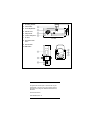
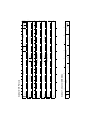
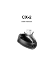
Acrobat
user manual
1
mounting bracket
2
swivel locks
3
focus adjustment
4
effects cover
5
lamp access
6
13 mm clamp hole
7
air vent
8
AC input & main
fuse
9
data sockets
10 DIP-switch
©1999 - 2001 Martin Professional A/S, Denmark.
All rights reserved. No part of this manual may be
reproduced, in any form or by any means, without
permission in writing from Martin Professional A/S,
Denmark.
Printed in Denmark.
P/N 35000039, Rev. H
Introduction . . . . . . . . . . . . . . . . . . . . . . . . . . . . . . . . . . . . . . . .4
Acrobat safety information . . . . . . . . . . . . . . . . . . . . . . . . . . . . . . . . . . . . . . . 4
Unpacking . . . . . . . . . . . . . . . . . . . . . . . . . . . . . . . . . . . . . . . . . . . . . . . . . . . . 5
Lamp replacement . . . . . . . . . . . . . . . . . . . . . . . . . . . . . . . . . . .6
AC power connection . . . . . . . . . . . . . . . . . . . . . . . . . . . . . . . .7
Installation . . . . . . . . . . . . . . . . . . . . . . . . . . . . . . . . . . . . . . . . .8
Data connection . . . . . . . . . . . . . . . . . . . . . . . . . . . . . . . . . . . .10
Recommended cable . . . . . . . . . . . . . . . . . . . . . . . . . . . . . . . . . . . . . . . . . . 10
Connections . . . . . . . . . . . . . . . . . . . . . . . . . . . . . . . . . . . . . . . . . . . . . . . . . 10
Stand-alone operation . . . . . . . . . . . . . . . . . . . . . . . . . . . . . . .12
Single unit operation . . . . . . . . . . . . . . . . . . . . . . . . . . . . . . . . . . . . . . . . . . . 12
Master / slave operation . . . . . . . . . . . . . . . . . . . . . . . . . . . . . . . . . . . . . . . . 12
Stand-alone settings . . . . . . . . . . . . . . . . . . . . . . . . . . . . . . . . . . . . . . . . . . . 13
MC-1 operation . . . . . . . . . . . . . . . . . . . . . . . . . . . . . . . . . . . . .14
MC-1 settings . . . . . . . . . . . . . . . . . . . . . . . . . . . . . . . . . . . . . . . . . . . . . . . . 14
DMX operation . . . . . . . . . . . . . . . . . . . . . . . . . . . . . . . . . . . . .15
DMX modes . . . . . . . . . . . . . . . . . . . . . . . . . . . . . . . . . . . . . . . . . . . . . . . . .
DMX address . . . . . . . . . . . . . . . . . . . . . . . . . . . . . . . . . . . . . . . . . . . . . . . .
1-channel DMX operation . . . . . . . . . . . . . . . . . . . . . . . . . . . . . . . . . . . . . . .
6/7-channel DMX operation . . . . . . . . . . . . . . . . . . . . . . . . . . . . . . . . . . . . .
15
15
17
17
Basic service . . . . . . . . . . . . . . . . . . . . . . . . . . . . . . . . . . . . . .18
Troubleshooting . . . . . . . . . . . . . . . . . . . . . . . . . . . . . . . . . . .19
DMX protocol . . . . . . . . . . . . . . . . . . . . . . . . . . . . . . . . . . . . . .21
Specifications . . . . . . . . . . . . . . . . . . . . . . . . . . . . . . . . . . . . .22
Acrobat user manual
3
1
INTRODUCTION
Thank you for selecting the Martin Acrobat. The Acrobat is an automated disco
lighting fixture that provides strobe effects, continuous electronic dimming, 18
color/gobo effects, a revolving mirror drum with variable swivel angle, adjustable
focus, and multiple control options.
ACROBAT SAFETY INFORMATION
Warning!
This product is not for household use. It presents risks of
lethal or severe injury due to fire and heat, electric shock, and
falls.
Read this manual before powering or installing the fixture, follow the safety
precautions listed below and observe all warnings in this manual and printed on
the fixture. If you have questions about how to operate the fixture safely, please
contact a Martin distributor for assistance.
To protect yoursel f and others fr om electr ic shock
• Disconnect the fixture from AC power before removing or installing the lamp,
fuses, or any part, and when not in use.
• Always ground (earth) the fixture electrically.
• Use only a source of AC power that complies with local building and electrical
codes and has both overload and ground-fault protection.
• Do not expose the fixture to rain or moisture.
• Refer all service to a qualified technician.
• Never operate the fixture with missing or damaged lenses and/or covers.
4
Introduction
Acrobat user manual
To protect yourself and others from burns and fi re
• Never attempt to bypass the thermostatic switch or fuses. Always replace
defective fuses with ones of the specified type and rating.
• Keep all combustible materials (for example fabric, wood, paper) at least 0.1
meters (4 inches) away from the fixture. Keep flammable materials well away
from the fixture.
• Do not illuminate surfaces within 0.3 meters (12 inches) of the fixture.
• Provide a minimum clearance of 0.1 meters (4 inches) around fans and air vents.
• Replace the lamp if it becomes defective or worn out. When replacing the lamp,
allow the fixture to cool for at least 5 minutes before opening the fixture or
removing the lamp. Protect your hands and eyes with gloves and safety glasses.
• Never place filters or other materials over the lens or mirror drum.
• The exterior of the fixture can reach temperatures up to 60° C (140° F). Allow the
fixture to cool for at least 5 minutes before handling.
• Do not operate the fixture if the ambient temperature (Ta) exceeds 40° C (104°
F).
To protect yourself and others from injury due to falls
• When suspending the fixture above ground level, verify that the structure can
hold at least 10 times the weight of all installed devices.
• Verify that all external covers and rigging hardware are securely fastened and use
an approved means of secondary attachment such as a safety cable.
• Block access below the work area whenever installing or removing the fixture.
UNPACKING
The packing material is carefully designed to protect the fixture during shipment
- always use it to transport the fixture.
The Acrobat comes with:
•
•
•
•
halogen lamp (installed)
mounting bracket
1.5-meter, 3-wire IEC power cable
user manual
Acrobat user manual
Introduction
5
2
LAMP REPLACEMENT
The Acrobat comes from the factory with a Philips 500 hour lamp installed. This
a 24V, 250W ELC halogen lamp. A high-output 50 hour lamp from Osram is also
available. Installing any other lamp may damage the fixture!
Lamp life can be extended beyond the stated average hours by reducing the lamp
voltage slightly using DIP-switch pin 12. Set pin 12 to ON for longer lamp life, or
OFF for maximum brightness.
Allow the lamp to cool for at least 5 minutes before packing and moving the
fixture. To avoid possible damage, remove the lamp when shipping the fixture.
Warning!
Always disconnect the fixture from AC power and allow it to
cool for 5 minutes before installing the lamp.
To install a l amp in the Acrobat
1 Disconnect the fixture from AC power. If replacing a lamp, allow it to cool for
5 minutes before removing the lamp access cover. The lamp cools faster with
the cover in place.
2 Remove both screws from the lamp access cover and lift the cover off.
3 If replacing a lamp, grasp the old lamp by the reflector and pull it out of the
holder. Then pull the socket off the lamp. Do not pull the wires.
4 Push the socket fully onto the pins of the new lamp.
5 Gently push the lamp into the holder until it snaps into place.
6 Replace the lamp access cover and screws.
6
Lamp replacement
Acrobat user manual
3
AC POWER CONNECTION
The Acrobat’s operating voltage is printed on the serial number label near the AC
input. Verify that the operating voltage closely matches the AC supply voltage
before applying power. Contact your Martin dealer if the operating voltage differs
from the supply voltage by more than five percent.
To install a plug on the mai ns lead
The fixture’s mains lead may require a grounding-type cord cap that fits your
power distribution cable or outlet. Consult a qualified electrician if you have
any doubts about proper installation.
Warning!
For protection from dangerous electric shock, the fixture
must be grounded (earthed). The AC mains supply shall have
overload and ground-fault protection.
Important! Verify that the feed cables are undamaged and rated for the
current requirements of all connected devices before use.
•
Following the cord cap manufacturer’s instructions, connect the yellow and
green wire to ground (earth), the brown wire to live, and the blue wire to
neutral. The table below shows some pin identification schemes.
Wire
Pin
Marking
Screw color
brown
live
“L”
yellow or brass
blue
neutral
“N”
silver
yellow/green
ground
Acrobat user manual
AC power connection
green
7
4
INSTALLATION
The Acrobat can be permanently installed or hung with a clamp (not included), or
it can be placed on the floor as described below. For maximum lamp life, do not
place the fixture directly on or beside a speaker cabinet or other source of strong
vibrations.
Once the Acrobat is installed and connected, the focus may be adjusted by
loosening and sliding the focus adjustment knob.
Warning!
Block access below the work area before proceeding.
Warning!
Always use a secure means of secondary attachment.
To install the mounting br acket
•
Install the mounting bracket on the chassis as shown. Place the washers on
the stud before the bracket.
To install or hang the Acrobat
1 Verify that the structure can support at least 10 times the weight of all
installed fixtures, clamps, cables, auxiliary equipment, etc.
2 If hanging the fixture with a rigging clamp, verify that the clamp is
undamaged and is designed for the fixture’s weight. Bolt the clamp securely
to the bracket with a grade 8.8 (minimum) M12 bolt and lock nut, or as
8
Installation
Acrobat user manual
recommended by the clamp manufacturer, through the clamp hole in the
mounting bracket.
3 If permanently installing the fixture, verify that the hardware (not included)
and mounting surface can bear at least 10 times the fixture’s weight. The four
6 mm holes and the clamp hole in the mounting bracket may be used for
attachment.
4 Working from a stable platform, clamp or fasten the fixture to the structure.
5 Install a safety cable that can hold at least 10
times the weight of the fixture through/over the
support and mounting bracket as shown.
6 Loosen the swivel locks, tilt the fixture to the
desired angle, and retighten.
7 Verify that the fixture is at least 0.3 meters (12
in.) from the surface to be illuminated and at
least 0.1 meters (4 in.) from any combustible
materials. Verify that the clearance around the
Rigging clamp not shown!
air vents is at least 0.1 meters (4 in.).
To use the br acket as a floor stand
The Acrobat may be placed on
the floor by standing it squarely
on the drum end or with the
support of the mounting bracket.
Never lay the fixture flat on its
back!
1 Install the mounting bracket as described above.
2 Set the fixture flat on its drum end or in one of the positions shown below.
Adjust the mounting bracket and tighten both swivel locks.
3 Verify (1) that the fixture is stable, (2) that the fixture is at least 0.3 meters (12
in.) from the surface to be illuminated and at least 0.1 meters (4 in.) from any
combustible materials, and (3) that the clearance around the air vents is at
least 0.1 meters (4 in.).
Acrobat user manual
Installation
9
5
DATA CONNECTION
This section describes how to connect fixtures to a controller.
RECOMMENDED CABLE
A reliable data connection begins with the right cable. Standard microphone cable
cannot transmit DMX data reliably over long runs. For best results, use cable
specifically designed for RS-485 applications. Your Martin dealer can supply
high quality cable in various lengths.
CONNECTIONS
The Acrobat’s XLR data sockets are wired with pin 1 to ground, pin 2 to signal (cold), and pin 3 to signal + (hot). This is the standard pin assignment for DMX
devices.
One or more adaptor cables may be required to connect the Acrobat to the
controller and/or other lights because many devices have 5-pin connectors and
others may have reversed signal polarity, that is, pin 2 hot and pin 3 cold.
5-pin to 3-pin
Adaptor
3-pin to 3-pin
Phase-Reversing
Adaptor
Male
Female
Male
Female
Male
Female
1
2
3
4
5
1
2
3
1
2
3
1
2
3
4
5
1
2
3
1
2
3
P/N 11820005
10
3-pin to 5-pin
Adaptor
P/N 11820004
Data connection
P/N 11820006
Acrobat user manual
To connect the data link
1 Connect a data cable to the controller’s output. If controller has a 5-pin
output, use a 5-pin male to 3-pin female adaptor cable (P/N 11820005).
2 Lead the data cable from the controller to the first fixture. Plug the cable into
the fixture’s data input.
3 Connect the output of the fixture closest to the controller to the input of the
next fixture. If connecting two fixtures with reversed polarity on pins 2 and 3,
insert a phase-reversing cable between the two fixtures.
4 Continue connecting fixtures output to input. Up to 32 devices may be
connected on a serial link.
5 Terminate the link by inserting a male termination plug (P/N 91613017) into
the data output of the last fixture. A termination plug is simply an XLR
connector with a 120 ohm, 0.25 W resistor soldered across pins 2 and 3.
Male
Termination Plug
Female
Termination Plug
Male XLR
Female XLR
1
2
3
120
P/N 91613017
Acrobat user manual
Data connection
1
2
3
120
P/N 91613018
11
6
STAND-ALONE OPERATION
The Acrobat may be operated without a controller in stand-alone mode. It may be
operated as a single unit or together with other Acrobats in “master/slave”
configuration.
Several options are available to modify stand-alone operation. These options are
selected using the DIP-switch as described below.
Important! The Acrobat transmits a signal when DIP-switch pins 2 and 10
are set to ON. To avoid damage to the electronics, connect no
more than 1 transmitting device (master or controller) to the
data link.
SINGLE UNIT OPERATION
The fixture defaults to stand-alone mode with music trigger whenever power is
applied and there is no control signal. Options for trigger type, mirror speed and
movement range, and lamp intensity may be selected as described under “Standalone settings”.
MASTER / SLAVE OPERATION
Multiple Acrobats can be connected together, without a controller, for
synchronized “master/slave” operation in which the slaves mimic the behavior of
the master.
To connect units for master / slave operation
1 Connect the output of one Acrobat to the input of the next Acrobat.
2 Connect additional Acrobats output to input. Up to 32 may be connected.
3 Terminate the link on both ends by inserting a female termination plug into
the data input of the first fixture and a male termination plug into the data
output of the last fixture. (The female terminator may not be required if the
first fixture is the master.) A termination plug is simply an XLR connector with
a 120 ohm, 0.25 W resistor soldered across pins 2 and 3.
12
Stand-alone operation
Acrobat user manual
To set the master
Important! Set only 1 fixture as master (DIP-switch pin 2 and 10 ON).
1 Set DIP-switch pins 2 and 10 to ON.
1
2
2 Set DIP-switch pins 3, 5, 6, 7, 8, 9, and 11 to OFF.
3 Select options with DIP-switch pins 1, 4, and 12.
To set a sl ave
1 Set DIP-switch 10 to ON.
2 Set pins 1, 2, 3, 4, 5 and 11 to OFF.
3 Select options with DIP-switch pins 6, 7, 8, 9, and 12.
STAND-ALONE SETTINGS
DIP-switch pins 1-9 enable stand-alone options only when pin 10 is ON. When
pin 10 is off, the DIP-switch selects a DMX address. Pin 11 must be OFF for
stand-alone operation.
Pin 12 selects lamp power and works in all modes. Set it to ON for reduced lamp
voltage and longer lamp life; set it to OFF for full intensity.
The DIP-switch 10 setting takes effect only after the fixture has been turned off
and on.
Fixture
single or
master
Option
Setting (0 = OFF, 1 = ON)
1
2
3
auto trigger
0
1
0
0
music trigger
1
1
0
0
1
0
slow movement
slave
Acrobat user manual
Random
color/gobo
0
Use a different
gobo in relation to
the master.
0
Rotate the mirror
drum in the
opposite direction
to the master.
0
Swivel the mirror
drum in the
opposite direction
to the master
0
Stand-alone operation
4
5
6
7
1
8
9
10
11
1
0
0
1
1
1
1
13
7
MC-1 OPERATION
All new Acrobats and older Acrobats with CPU firmware v 1.4 or higher are fully
compatible with the Martin MC-1 Controller. See the MC-1 user manual for
additional information.
MC-1 SETTINGS
DIP-switch pin 10 must be set to OFF to enable MC-1 mode operation. Changes
to the setting take effect after the fixture has been turned off and on.
DIP-switch pins 6, 7, 8, and 9 select several control options that can be combined
to achieve powerful effects quickly and easily.
Pin 12 selects lamp power and works in all modes. Set it to ON for reduced lamp
voltage and longer lamp life; set it to OFF for full intensity.
Option
Setting (0 = OFF, 1 = ON)
1
2
3
Inverted parabolic reflector
4
5
6
Use a different color/gobo.
8
9
0
1
Swivel
11
0
1
Swivel the mirror drum in
the opposite direction (to
that requested by the MC1)
10
0
1
Rotate the mirror drum in
the opposite direction (to
that requested by the MC1)
14
7
1
0
Rotate
MC-1 operation
Acrobat user manual
DMX OPERATION
8
DMX MODES
The Acrobat has 3 DMX modes to choose from: a 1-channel mode that provides
control of the built-in stand-alone features, a 6-channel mode that provides
position control of all effects plus speed control of the drum swivel movement,
and an “extended” 7-channel mode that in addition provides speed control of the
effect wheel.
To select DMX mode
1 Disconnect the fixture from power. Set DIP-switch pin 10 to OFF.
2 To select 1-channel DMX mode, set DIP-switch pin 11 to ON.
3 To select 6-channel DMX mode, set DIP-switch pin 11 to OFF. The 6/7 ch.
jumper is set at the factory for 6 channel mode, which is recommended for
most applications.
4 To select 7-channel DMX mode, set DIP-switch pin 11 to OFF. Set the 6/7 ch.
jumper for 7 channels as described on page 18.
DMX ADDRESS
DIP-switch pins 1-9 are used to set the control address. The address, also known
as the start channel, is the first channel used to receive instructions from the
controller.
For independent control, each fixture must be assigned its own address and nonoverlapping control channels. Two Acrobats may share the same address only if
they are to respond identically: they will receive the same instructions and
individual control will not be possible.
To select DMX address
1 Select an address for the fixture on your controller. Look up the DIP-switch
setting for the address in the DIP-switch settings table below.
2 Disconnect the fixture from power.
Acrobat user manual
DMX operation
15
3 Set pins 1 through 9 to the ON (1) or OFF (0) position as listed in the table.
Find the address in the table below. Read the settings for pins 1 - 5 to the left and
read the settings for pins 6 - 9 above the address. “0” means OFF and “1” means
ON. Pin 10 is always OFF for DMX operation.
',36ZLWFK6HWWLQJ
2))
21
#1
0
1
0
1
0
1
0
1
0
1
0
1
0
1
0
1
0
1
0
1
0
1
0
1
0
1
0
1
0
1
0
1
16
#2
0
0
1
1
0
0
1
1
0
0
1
1
0
0
1
1
0
0
1
1
0
0
1
1
0
0
1
1
0
0
1
1
#3
0
0
0
0
1
1
1
1
0
0
0
0
1
1
1
1
0
0
0
0
1
1
1
1
0
0
0
0
1
1
1
1
#4
0
0
0
0
0
0
0
0
1
1
1
1
1
1
1
1
0
0
0
0
0
0
0
0
1
1
1
1
1
1
1
1
#5
0
0
0
0
0
0
0
0
0
0
0
0
0
0
0
0
1
1
1
1
1
1
1
1
1
1
1
1
1
1
1
1
#9
#8
#7
#6
0
0
0
0
0
0
0
1
0
0
1
0
0
0
1
1
0
1
0
0
0
1
0
1
0
1
1
0
0
1
1
1
1
0
0
0
1
0
0
1
1
0
1
0
1
0
1
1
1
1
0
0
1
1
0
1
1
1
1
0
1
1
1
1
1
2
3
4
5
6
7
8
9
10
11
12
13
14
15
16
17
18
19
20
21
22
23
24
25
26
27
28
29
30
31
32
33
34
35
36
37
38
39
40
41
42
43
44
45
46
47
48
49
50
51
52
53
54
55
56
57
58
59
60
61
62
63
64
65
66
67
68
69
70
71
72
73
74
75
76
77
78
79
80
81
82
83
84
85
86
87
88
89
90
91
92
93
94
95
96
97
98
99
100
101
102
103
104
105
106
107
108
109
110
111
112
113
114
115
116
117
118
119
120
121
122
123
124
125
126
127
128
129
130
131
132
133
134
135
136
137
138
139
140
141
142
143
144
145
146
147
148
149
150
151
152
153
154
155
156
157
158
159
160
161
162
163
164
165
166
167
168
169
170
171
172
173
174
175
176
177
178
179
180
181
182
183
184
185
186
187
188
189
190
191
192
193
194
195
196
197
198
199
200
201
202
203
204
205
206
207
208
209
210
211
212
213
214
215
216
217
218
219
220
221
222
223
224
225
226
227
228
229
230
231
232
233
234
235
236
237
238
239
240
241
242
243
244
245
246
247
248
249
250
251
252
253
254
255
256
257
258
259
260
261
262
263
264
265
266
267
268
269
270
271
272
273
274
275
276
277
278
279
280
281
282
283
284
285
286
287
288
289
290
291
292
293
294
295
296
297
298
299
300
301
302
303
304
305
306
307
308
309
310
311
312
313
314
315
316
317
318
319
320
321
322
323
324
325
326
327
328
329
330
331
332
333
334
335
336
337
338
339
340
341
342
343
344
345
346
347
348
349
350
351
352
353
354
355
356
357
358
359
360
361
362
363
364
365
366
367
368
369
370
371
372
373
374
375
376
377
378
379
380
381
382
383
384
385
386
387
388
389
390
391
392
393
394
395
396
397
398
399
400
401
402
403
404
405
406
407
408
409
410
411
412
413
414
415
416
417
418
419
420
421
422
423
424
425
426
427
428
429
430
431
432
433
434
435
436
437
438
439
440
441
442
443
444
445
446
447
448
449
450
451
452
453
454
455
456
457
458
459
460
461
462
463
464
465
466
467
468
469
470
471
472
473
474
475
476
477
478
479
480
481
482
483
484
485
486
487
488
489
490
491
492
493
494
495
496
497
498
499
500
501
502
503
504
505
506
507
508
509
510
511
DMX operation
Acrobat user manual
1-CHANNEL DMX OPERATION
The functions shown in the following table are available in 1-channel mode.
When a “stand-alone” function is selected, the fixture steps through a routine
using a built-in microphone to trigger the action to the beat of the music. Note
that multiple fixtures cannot be synchronized in this mode.
DMX value
Percent
Function
0 - 10
11 - 20
21 - 80
81 - 115
116 - 140
141 - 175
176 - 210
211 - 255
0-4
5-7
8 - 31
32 - 45
46 - 55
56 - 68
69 - 82
83 - 100
Blackout (light off)
Open (light on)
Strobe
Stand-alone with slow music trigger
Stand-alone with medium music trigger
Stand-alone with fast music trigger
Stand-alone with random music trigger
Manual trigger area, crossover at 240 (94%)
6/7-CHANNEL DMX OPERATION
The 6 and 7 channel modes provide all functions listed in the DMX protocol on
page 21.
Channel 1 controls the light intensity and the strobe rate. It also allows you to
execute a random “stand-alone” program using automatic or music trigger, and to
reset the fixture to its home position.
Channel 2 controls the rotation of the parabolic reflector. This channel has no
effect if the stand-alone program is selected on channel 1.
Channel 3 controls the color/gobo wheel. This channel functions even if the
stand-alone program is selected. When strobe is selected, the wheel alternates
between the selected position and the one before it. To strobe between open and
closed, select the open position.
Channel 4 controls the mirror drum’s swivel angle.
Channel 5 controls mirror drum rotation. Channels 4 and 5 have no effect if the
stand-alone program is selected.
Channel 6 controls the drum’s swivel speed, allowing you to vary the speed with
controllers without cross-fade times. If your controller has cross-faders and you
use them, turn the speed function off by setting channel 6 to 0 percent. This
channel has no effect if stand-alone is selected.
Channel 7 provides speed control of the effect wheel, allowing you to program
slow transitions from one effect to another.
Acrobat user manual
DMX operation
17
BASIC
9
SERVICE
To set the 6/7-ch. DMX jumper
1 Disconnect the fixture from power.
2 Remove the effects section cover. It is secured by 5 Torx-20 screws: 3 on the
side with print and 2 on the other side.
3 Locate PL 118 on the printed circuit board, next to DIP-switch pin 12.
4 Using a pair of tweezers or similar tool, place the jumper on 1 of the 2 pins, or
remove it completely, for 6-channel DMX operation. Place the jumper on both
pins to enable 7-channel DMX operation.
5 Replace the cover before applying power.
To replace the main fuse
1 Unplug the mains cable from the input socket. Pry open the fuse holder and
remove the fuse.
2 Replace the fuse with one of the same type. The fuse rating is listed on serial
number label.
18
Basic service
Acrobat user manual
10
TROUBLESHOOTING
Problem
Probable cause(s)
No power to fixture.
Fixture is completely dead.
Fixture resets correctly but does
not respond to controller.
Intermittent flicker or strange
behavior.
Effect fails to reset correctly.
No light.
Lamp cuts out intermittently or
burns out too quickly.
Acrobat user manual
Remedy
Check that power is switched on
and cables are plugged in.
Primary fuse blown.
Replace fuse.
Secondary fuse blown.
Contact Martin technician for
service.
The DMX signal is not
transmitted.
Connect controller. Inspect
connections and cables. Correct
poor connections. Repair or
replace damaged cables.
The DMX data signal is
reversed.
Insert a phase-reversing cable in
the link before the fixture.
Incorrect address or other DIPswitch setting.
Check DIP-switch settings.
Data link not terminated.
Insert termination plug in output
of the last fixture on the link.
One of the fixtures is
transmitting as a master or is
defective.
Bypass one fixture at a time
until normal operation is
regained: unplug both
connectors and connect them
directly together. Have the
defective fixture serviced by a
qualified technician.
The effect requires mechanical
adjustment.
Contact Martin technician for
service.
Lamp missing or blown
Disconnect fixture and replace
lamp.
Extreme vibrations.
Relocate fixture away from
speakers.
The operating voltage does not
match AC supply.
Contact Martin technician for
service.
Blocked air vent.
Increase clearance around
fixture.
Dust buildup inside fixture.
Contact Martin technician for
professional cleaning.
Troubleshooting
19
7
6
white
s
left
2
10
25
10
25
10
25
10
3
4
20
50
20
50
20
50
20
50
6
CW rotation
5
CCW rotation
7
30
75
30
75
30
75
30
DIMMER
75
B/O
ON
LIGHT
25
10
50
STROBE
20
75
30
Acrobat 1-Channel DMX Mode
fast
o
f
f fast
o
p slow
5 t
4
3
closed
p slow
2 ot
s
1 B/
O
25
Acrobat DMX Protocol
8
50
stop fast
125
MIRROR PAN SPEED
fast
MIRROR DRUM ROTATION
125
MIRROR DRUM PAN
50
COLOR/GOBO EFFECTS
10
11
12
125
fast stop fast
PARABOLIC REFLECTOR
50
125
60
150
60
150
13
150
60
open
150
100
slow
40
40
125
medium
50
50
14
open
150
MUSIC TRIGGER
fast
60
60
COLOR/GOBO SPEED (EXTENDED MODE)
100
40
100
40
9
100
40
100
175
175
175
15
175
fast
175
70
70
70
70
70
200
17
random
200
200
CCW rotation
16
200
CW rotation
80
80
80
80
80
STROBE
200
18
225
225
90
90
90
ÅÆ
225
250
slow
250
slow
s
t
o
slowp
250
right
closed Stand-alone
90
MANUAL TRIGGER
19
225
s
t
o
slow p
250
250
R
STAND-ALONE e
s
slow music auto et
90
225
A
DMX PROTOCOL
Channel
1
2
3
4
5
6
7*
Value
Percent
0-4
5 - 154
155 - 169
170 - 229
230 - 239
240 - 249
250 - 255
0-1
2 - 60
61 - 66
67 - 89
90 - 93
94 - 97
98 - 100
0-1
2 - 122
123 - 132
133 - 253
254 - 255
0-1
1 - 48
49 - 52
52 - 99
99 - 100
0 - 11
12 - 23
24 - 35
36 - 47
48 - 59
60 - 71
72 - 83
84 - 95
96 - 107
108 - 119
120 - 131
132 - 143
144 - 155
156 - 167
168 - 179
180 - 191
192 - 203
204 - 215
216 - 227
228 - 239
240 - 255
0-4
5-8
9 - 13
14 - 18
19 - 23
24 - 27
28 - 32
33 - 37
38 - 41
42 - 46
47 - 51
52 - 55
56 - 60
61 - 65
66 - 70
71 - 74
75 - 79
80 - 84
85 - 88
89 - 96
97 - 100
0 - 255
0 - 100
0-1
2 - 122
123 - 132
133 - 253
254 - 255
0-1
1 - 48
49 - 52
52 - 99
99 - 100
0-2
3 - 255
0-1
2 - 100
0 - 255
0 - 100
Acrobat user manual
Function
Dimmer, Strobe, Reset
Light off
Dimmer, closed to open
Dimmer full open
Strobe, fast to slow
Stand-alone, music trigger
Stand-alone, auto trigger
Reset
Parabolic Reflector
Stop
CCW rotation, slow to fast
Stop
CW rotation, fast to slow
Stop
Color / Gobo Wheel
Open
Worms
Web
Petals
Spokes
Cone
Maze
Crater
Holes
Cross
Jagged Cross
Atomic
Dot Circle
Nordic
Aim
Pie
Tie
Nova
Triple Beam
Blackout
Random “stand-alone” position w/ music or auto trigger
Mirror Drum Swivel
Left to right (127 = neutral)
Mirror Drum Rotation
Stop
CW rotation, slow to fast
Stop
CCW rotation, fast to slow
Stop
Mirror Swivel Speed
Tracking (speed function off)
Fast to slow
Color / Gobo Speed (*extended mode only)
Fast to slow
DMX protocol
21
B
S PECIFICATIONS
PHYSICAL
• Size (L x W x H) .................................. 490 x 165 x 190 mm (19.3 x 6.5 x 7.5 in)
• Weight ............................................................................................. 8 kg (17.5 lbs)
THERMAL
• Maximum ambient temperature (Ta)................................................40° C (104° F)
• Maximum surface temperature ........................................................60° C (140° F)
CONTROL AND PROGRAMMING
• Data pin-out............. 3-pin locking XLR, pin 1 shield, pin 2 cold (-), pin 3 hot (+)
• Control protocol ..............................................................USITT DMX-512 (1990)
• DMX channels ................................................................................................... 1/6
AC POWER
•
•
•
•
•
Input ............................................................................... 3-prong IEC male socket
Maximum power and current............................................. 275 W, 1.2 A @ 230 V
Primary fuse, EU version ........................................2.5 AT / 250 V, P/N 05020010
Primary fuse, US version ........................................5.0 AT / 250 V, P/N 05020018
Secondary fuse ........................................................2.0 AT / 250 V, P/N 05020009
INSTALLATION
• Minimum distance to combustible materials ...................................... 0.1 m (4 in)
• Minimum distance to illuminated surfaces ....................................... 0.3 m (12 in)
• Minimum clearance around fan and air vents...................................... 0.1 m (4 in)
ACCESSORIES
•
•
•
•
•
•
22
MC-1 controller, EU ............................................................................... 90718000
MC-1 controller, US................................................................................ 90718100
Osram 24V/250W ELC 50 h halogen lamp............................................ 97000104
Philips 24V/250W ELC 500 h halogen lamp.......................................... 97000107
G-clamp .................................................................................................. 91602003
Half-coupler clamp ................................................................................ 91602005
Specifications
Acrobat user manual
Acrobat user manual
Specifications
23