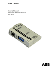
1
ACS 160
Installation and
Start-up Guide
RS485 and RS232
Adapter Module CFB-RS
RS485 and RS232
Adapter Module CFB-RS
Installation and
Start-up Guide
3BFE 64390431 R0125
EN
EFFECTIVE: 23.3.2001
Safety Instructions
Overview
This chapter states the safety instructions that must be followed when installing
and operating the RS485/RS232 adapter. If neglected, physical injury and
death may follow, or damage may occur to the frequency converter, the motor
and driven equipment. The material in this chapter must be studied before
attempting any work on, or with, the unit.
Warnings
Warnings are used to inform of conditions which can, if proper steps are not
taken, lead to a serious fault condition, physical injury and death.
Readers are informed of situations that can result in serious physical injury
and/or serious damage to equipment with the following symbols:
Dangerous Voltage Warning: warns of situations in which a high
voltage can cause physical injury and/or damage equipment. The
text next to this symbol describes ways to avoid the danger.
General Warning: warns of situations which can cause physical
injury and/or damage equipment by means other than electrical.
The text next to this symbol describes ways to avoid the danger.
RS485 and RS232 Adapter Installation and Start-up Guide
i
Safety Instructions
ii
RS485 and RS232 Adapter Installation and Start-up Guide
Table of Contents
Safety Instructions
Overview ...................................................................................................... i
Warnings ...................................................................................................... i
Chapter 1 –Introduction
Overview .................................................................................................. 1-1
Delivery Check ......................................................................................... 1-1
How to Use This Guide ............................................................................ 1-1
Chapter 2 – Installation
Mounting .................................................................................................. 2-2
Connectors and Switches ........................................................................ 2-3
Selecting the Communication Speed ....................................................... 2-4
Selecting RS485 or RS232 Mode ............................................................ 2-5
RS485 Bus Termination ........................................................................... 2-5
Installation to RS485 Bus ......................................................................... 2-6
Installation to RS232 Bus ......................................................................... 2-8
Earthing and Termination ....................................................................... 2-11
Chapter 3 – Programming
General ....................................................................................................
Communication Settings ..........................................................................
Control Locations .....................................................................................
Diagnostic Counters .................................................................................
3-1
3-2
3-5
3-6
Chapter 4 – Communication
Introduction to Modbus.............................................................................
Register Read and Write ..........................................................................
Register Mapping .....................................................................................
Exception Codes ......................................................................................
Function Codes ........................................................................................
The Control Word and the Status Word ...................................................
RS485 and RS232 Adapter Installation and Start-up Guide
4-1
4-1
4-2
4-3
4-4
4-4
iii
References............................................................................................... 4-8
Actual Values ......................................................................................... 4-11
Fault and Alarm Status .......................................................................... 4-13
Chapter 5 – Fault Tracing
Appendix A – Parameter Scaling
Effect of Resolution.................................................................................. A-1
Signed Values .......................................................................................... A-1
Appendix B– Technical Data
RS-485 Link ............................................................................................. B-1
CFB-RS.................................................................................................... B-1
Appendix C– Ambient Conditions
Operation ................................................................................................ C-1
Storage and Transportation .................................................................... C-1
iv
RS485 and RS232 Adapter Installation and Start-up Guide
Chapter 1 –Introduction
Overview
The RS485 and RS232 adapter is used for connecting the ACS 160 frequency
converter to a serial Modbus (RS232 or RS485) network. The adapter is IP65
protected for use in demanding environmental conditions.
Delivery Check
The option package includes:
• RS485/RS232 Adapter
• Installation and Start-up Guide for RS485 and RS232 Adapter
• Two M16 x 1,5 cable glands with O-ring.
• Two M4 x 12 mounting screws
How to Use This Guide
The purpose of this Guide is to provide the information necessary to install,
commission, use, and to fault diagnose the adapter.
Safety Instructions describe the formats for warnings and notations used within
this guide. This chapter also states the safety instructions which apply to the
installation and operation of the RS485/RS232 Adapter.
Chapter 1 – Introduction, the chapter you are reading now, contains a short
description of this manual and a list of related publications.
Chapter 2 – Installation contains instructions for mechanical and electrical
installation of the adapter.
Chapter 3 – Programming explains how to program the ACS 160 drive for
Modbus communication.
Chapter 4 – Communication describes the Modbus communication on
ACS 160 drives.
Chapter 5 – Fault Tracing describes how to diagnose the most common
problems with the adapter.
RS485 and RS232 Adapter Installation and Start-up Guide
1-1
Chapter 1 –Introduction
Appendix A– Parameter Scaling describes the scaling when parameters are
accessed through the Modbus network.
Appendix B– Technical data of the module.
Appendix C– Ambient conditions.
Conventions Used in This Guide
This manual uses some terms and conventions which might not be known to
every user of this manual. Some of these terms are described below.
4XXXX Register Area
Modicon PLCs have a signed integer data table area, which is used for
Analogue Output modules and for storing temporary or set-point values. These
registers are in the address area starting from 40001. The last register address
available on PLCs depends on the available memory, but is less than 49999.
The ACS 160 drive simulates this area by providing a read and write access to
its parameters through this register address area.
Related Publications
ACS 160 User’s Manual.
1-2
RS485 and RS232 Adapter Installation and Start-up Guide
Chapter 2 – Installation
This chapter contains instructions for setting up the RS485/RS232 adapter.
WARNING! Verify that the ACS 160 is not powered before starting
the installation. Follow the safety instructions given in this Guide
and in the ACS 160 User’s Manual.
Drive connection Cable
Base
Mounting Screws
(2 pcs)
Cover Screws
(4 pcs)
Circuit Board
Assembly
Cover
Cable Glands
for Bus Cables
(2 pcs)
Figure 2-1 Exploded view of the CFB-RS Adapter Module
RS485 and RS232 Adapter Installation and Start-up Guide
2-1
Chapter 2 – Installation
Mounting
The CFB-RS can be mounted onto the ACS 160 drive with two screws as
shown in the ACS 160 User's Manual. This also provides the earthing of the
module housing.
The CFB-RS uses the control panel connector of the drive. The CFB-RS is
powered through this connector.
The CFB-RS provides two cable entries for the incoming and outgoing bus
cables. The cables are connected to a detachable terminal header.
If only one bus cable is connected, the unused cable entry should be plugged.
Remove the front cover to access the configuration switches and jumpers.
2-2
RS485 and RS232 Adapter Installation and Start-up Guide
Chapter 2 – Installation
Connectors and Switches
The adapter operates either in RS232 mode or RS485 mode. The mode can be
selected with a jumper. By default, the adapter operates in RS485 mode at a
communication speed of 9600 bps (bits per second).
RS485 terminal X1
RS232 terminal X4
1 2 3 45
RS323/RS485 mode
selection jumper S3
RS485 bus termination
switch S1
1 2 3 45
RS485 terminal X2
Communication
speed setting
DIP switch S2
LEDs:
TxD
RxD
Power
Figure 2-2 Connectors and switches.
RS485 and RS232 Adapter Installation and Start-up Guide
2-3
Chapter 2 – Installation
Selecting the Communication Speed
Communication speed is selected by DIP switch S2 and by parameter 5201
COMM SPEED. The factory setting for the communication speed is 9600 bps (bits
per second).
Communication speed setting using DIP switch S2 is needed only when the
adapter operates in RS485 mode.
DIP switch S2 Communication speed
ON
300 bps
1 2 3
ON
600 bps
1 2 3
ON
1200 bps
1 2 3
ON
2400 bps
1 2 3
ON
4800 bps
1 2 3
ON
9600 bps
1 2 3
ON
19200 bps
1 2 3
1 2 3
Figure 2-3 Selecting the communication speed for the adapter.
2-4
RS485 and RS232 Adapter Installation and Start-up Guide
Chapter 2 – Installation
Selecting RS485 or RS232 Mode
The adapter operates either in RS232 mode or in RS485 mode, selectable by a
jumper. As a factory setting, the adapter operates in RS485 mode.
Jumper S3 Mode
RS485
1
S3
RS232
2
Figure 2-4 Selecting the operating mode.
RS485 Bus Termination
The RS485 bus must be terminated using 120 9 resistors at both ends of the
network. The adapter has built-in termination resistors that can be enabled by
the bus termination switch S1. Refer to 'Earthing and Termination' on page 211. By default, bus termination is enabled (ON).
Bus termination switch
S1
Figure 2-5 Selecting RS485 termination impedance.
RS485 and RS232 Adapter Installation and Start-up Guide
2-5
Chapter 2 – Installation
Installation to RS485 Bus
1 Make sure power is not connected to the ACS 160.
2 Set the adapter switches:
• Confirm that the operation mode is RS485 (jumper S3)
• Set communication speed of the adapter with DIP switch S2
• If the termination is not needed, use switch S1 to disable it.
3 Mount the adapter on the side of the ACS 160. Leave the drive connection
cable disconnected.
4 Wire the adapter to the RS485 network (X1 and X2).
5 Connect the control panel to the drive.
6 Connect power to ACS 160.
7 Set up communication: Station number, communication speed of the drive
and parity. Refer to Chapter 3 – Programming.
8 Set up other drive parameters as needed. Refer to ACS 160 User’s Manual
and Chapter 3 of this manual.
9 Disconnect power from the ACS 160.
10 Disconnect control panel and connect drive connection cable of the adapter.
Wiring
The RS485 link is a daisy-chained bus, without dropout lines. The RS485 link
should also be terminated on both physical ends of the wire to reduce the noise
on the network.
Modbus network should be wired using Belden 9841 or equivalent. Belden
9841 is a single twisted shielded pair cable with a wave impedance of 120 9.
The network should be connected according to Figure 2-6 below.
12345
12345
Figure 2-6 RS485 wiring.
2-6
RS485 and RS232 Adapter Installation and Start-up Guide
Chapter 2 – Installation
Table 2-1 RS485 connection terminals. Terminals X1 and X2 are connected in
parallel.
X1, X2
1
2
C
3
4
5
A
B
Shield
Description
No connection
Common. Connected to ACS 160
chassis through 100 9 impedance
Data negative
Data positive
Cable shield
RS485 terminal X1
RS485 terminal X2
Figure 2-7 RS485 connection terminals X1 and X2.
RS485 and RS232 Adapter Installation and Start-up Guide
2-7
Chapter 2 – Installation
Installation to RS232 Bus
1 Make sure power is not connected to the ACS 160.
2 Confirm that the operation mode is RS232 (jumper S3).
3 Mount the adapter on the side of the ACS 160.
4 Connect the control panel to the drive.*
5 Connect power to ACS 160. *
6 Set up communication: Station number, communication speed of the drive
and parity. Refer to Chapter 3 – Programming. *
7 Set up other drive parameters as needed. Refer to ACS 160 User’s Manual
and Chapter 3 of this manual. *
8 Disconnect power from the ACS 160.
9 Disconnect control panel.
10 Connect drive connection cable of the adapter. Plug in the RS232 cable
(X4).
* These steps can be ignored when using DriveWindow Light PC tool, or when
the default communication settings are used.
2-8
RS485 and RS232 Adapter Installation and Start-up Guide
Chapter 2 – Installation
Wiring
RS232 bus is a point-to-point type bus. Typical usage is to temporarily connect
the drive into the serial port of a PC. Cover of the adapter module can not be
closed when RS232 connector is used.
The maximum RS232 cable length is 3 meters. The RS232 cable is not
included in the delivery.
PC
ACS 160
Serial Port
Max Cable length 3 m
Figure 2-8 RS232 wiring.
RS485 and RS232 Adapter Installation and Start-up Guide
2-9
Chapter 2 – Installation
X4
5
4
9
3
8
2
7
X4
1
6
Description
1
NC
2
TxD
3
RxD
4
DTR
5
SGND
6
DSR
7
RTS
8
CTS
9
NC
Figure 2-9 RS232 signals. DTR and DSR as well as RTS and CTS signals are
internally connected. The RS232 cable should not have TxD and RxD signals
connected across.
2-10
RS485 and RS232 Adapter Installation and Start-up Guide
Chapter 2 – Installation
Earthing and Termination
RS485 Bus
The RS485 network should not be directly earthed at any point. All the devices
on the network should be well earthed using their corresponding earthing
terminals.
As always, the earthing wires should not form any closed loops, and all the
devices should be earthed to a common earth.
The RS485 network must be terminated using 120 9 resistors at both ends of
the network as shown in Figure 2-10. These resistors are already resident on
the adapter. Use switch S1 to connect the termination resistors.
Terminated
Terminated
Figure 2-10 Termination for the RS485 link.
The connections may only be made with the drive disconnected from the
power source.
RS485 and RS232 Adapter Installation and Start-up Guide
2-11
Chapter 2 – Installation
2-12
RS485 and RS232 Adapter Installation and Start-up Guide
Chapter 3 – Programming
This chapter describes how to program the ACS 160 drive for Modbus
communication.The reader should be already familiar with programming the
drive parameters using the control panel, and the way the parameters are
arranged in groups. For details, see the ACS 160 User’s Manual.
General
When power is connected, the ACS 160 will automatically check for the
presence of the panel.
If the panel is NOT detected in 7 seconds after power up, the ACS 160 will set
up Modbus communication normally, using the parameters 5201 STATION ID,
5202 COMM SPEED and 5203 PARITY. This communication setting is then used
until the next power-down.
Note! If any of the parameters 5201 STATION ID, 5202 COMM SPEED and 5203
PARITY has been altered, the control panel will operate only if it is connected
before the power is applied to the ACS 160 (or immediately after power-up).
Note! If any of the parameters 5201 STATION ID, 5202 COMM SPEED and 5203
PARITY is altered, the modification takes effect only on the next power-up, and if
the control panel is not connected when the power is applied.
RS485 and RS232 Adapter Installation and Start-up Guide
3-1
Chapter 3 – Programming
Communication Settings
The configuration information is in Group 52. The contents of this group are
shown in Table 3-1 below.
Table 3-1 Communication parameters.
Code
Name
Group 52
SERIAL COMM
5201
STATION NUMBER
5202
COMM SPEED
5203
5204
5205
3-2
PARITY
COMM FAULT TIME
COMM FAULT FUNC
Range
1 - 247
3 = 300 bps
6 = 600 bps
12 = 1200 bps
24 = 2400 bps
48 = 4800 bps
96 = 9600 bps
192 = 19200 bps
0-2
0.1 - 60.0 s
0-3
Default
User
1
96 (9600 bps)
0 (NONE)
1.0 s
0 (NOT SEL)
RS485 and RS232 Adapter Installation and Start-up Guide
Chapter 3 – Programming
Code
Name
5201
STATION NUMBER
Sets the slave number for the ACS 160 in Modbus network.
Range: 1 - 247
Note! Modifications take effect only on the next power up.
5202
COMM SPEED
Defines the communication speed of the ACS 160 in bits per second
(bps).
3 = 300 bps
48 = 4800 bps
6 = 600 bps
96 = 9600 bps
12 = 1200 bps 192 = 19200 bps
24 = 2400 bps
Note! Modifications take effect only on the next power-up.
5203
PARITY
Defines the parity to be used in Modbus communication. Parameter also
defines the number of stop bits. In Modbus communication, the number
of stop bits is 2 with no parity bit, and 1 with even or odd parity.
0 = NONE
1 = EVEN
2 = ODD
Note! Modifications take effect only on the next power-up.
5204
COMM FAULT TIME
Time limit for communication loss detection. This parameter is used
together with parameter 5205 COMM FAULT FUNC to define the ACS 160
operation when the communication with the master device in the Modbus
network is lost.
The master device in the Modbus network must signal its presence to
every slave device (ACS 160) in the network by periodically writing
Command Word, External Reference 1 or External Reference 2 to each
ACS 160 in the network. Maximum write period is set by this parameter.
Range: 0.1 - 60.0 s
Note! During the first 4 seconds after power-up, communication fault is
not evaluated to compensate for possible long system start-up delay.
RS485 and RS232 Adapter Installation and Start-up Guide
3-3
Chapter 3 – Programming
Code
Name
5205
COMM FAULT FUNC
Operation in case the communication with the master device is lost. The
time limit for communication loss detection is set by parameter 5204
COMM FAULT TIME.
0 = NOT SEL
Communication loss is not detected.
1 = FAULT
A fault indication is shown on the control panel display and included in the
Status Word. The ACS 160 coasts to stop.
2 = CONST SPEED 7
A warning indication is shown on the control panel display and included in
the Status Word. The speed reverts to the level set by parameter 1208
CONST SPEED 7.
3 = LAST SPEED
A warning indication is shown on the control panel display and included in
the Status Word. The speed reverts to the level set by the current
frequency reference.
Warning! If CONST SPEED 7 or LAST SPEED is selected, ensure it
is safe to continue operation in case communication with the
master device fails.
3-4
RS485 and RS232 Adapter Installation and Start-up Guide
Chapter 3 – Programming
Control Locations
The ACS 160 drive can receive control signals from multiple sources (such as
the digital and analogue inputs, the control panel, and a fieldbus adapter). The
user can separately determine the source for each type of control information.
Especially refer to parameter groups 10, 11 and 16 in the ACS 160 User’s
Manual for information on the selection parameters.
RS485 and RS232 Adapter Installation and Start-up Guide
3-5
Chapter 3 – Programming
Diagnostic Counters
Diagnostic counters can be used for debugging the Modbus system.
Counters will roll over from 65535 to 0. The counter values are stored to
permanent memory when power is disconnected.
Counters can be reset from the control panel by pressing the UP and DOWN
buttons simultaneously when in parameter set mode, or by setting them to zero
via the serial communication channel.
Code
Name
Range
Group 52
SERIAL COMM
5206
BAD MESSAGES
5207
GOOD MESSAGES
5208
BUFFER OVERRUNS
5209
FRAME ERROS
5210
PARITY ERROS
5211
CRC ERROS
5212
BUSY ERROS
5213
SER FAULT MEM 1
5214
SER FAULT MEM 2
5215
SER FAULT MEM 3
User
0 - 65535
0 - 65535
0 - 65535
0 - 65535
0 - 65535
0 - 65535
0 - 65535
0-3
0-3
0-3
Note! Parameters 5206 - 5212 are displayed in hexadecimal format by the
control panel. The panel displays three decimal points to indicate a
hexadecimal number control panel.
0.A.1.4
Figure 3-1 An example of the control panel displaying a hexadecimal number
A14 (2580 decimal).
3-6
RS485 and RS232 Adapter Installation and Start-up Guide
Chapter 3 – Programming
Code Description
5206
BAD MESSAGES
This diagnostics counter increases by one every time the ACS 160 finds
any kind of communication error. During normal operation, this counter
hardly ever increases.
5207
GOOD MESSAGES
This diagnostics counter increases by one every time a valid Modbus
message has been received by the ACS 160. During normal operation, this
counter increases constantly.
5208
BUFFER OVERRUNS
The longest possible message length for the ACS 160 is 32 bytes. If a
message exceeding 32 bytes is received, this diagnostic counter increases
by one every time a character is received and cannot be placed in the
buffer.
5209
FRAME ERRORS
This diagnostic counter increases by one every time when a character with
a framing error is received from the bus.
• Communication speed settings of the devices connected to the bus
differ.
• Ambient noise levels may be too high.
5210
PARITY ERRORS
This diagnostic counter increases by one every time when a character with
a parity error is received from the bus.
• Parity settings of the devices connected in the bus differ.
• Ambient noise levels may be too high.
5211
CRC ERRORS
This diagnostic counter increases by one every time when a message with
a CRC error is received.
• Ambient noise levels may be too high.
• CRC calculation is not performed correctly.
RS485 and RS232 Adapter Installation and Start-up Guide
3-7
Chapter 3 – Programming
Code Description
5212
BUSY ERRORS
In Modbus network, only one device can transmit at any given time. This
diagnostic counter increases by one every time the ACS 160 receives a
character from the bus while it is still processing the previous message.
5213
SER FAULT MEM 1
Last Modbus exception code sent. Refer to "Exception Codes" on page 4-3.
5214
SER FAULT MEM 2
Previous Modbus exception code sent.
5215
SER FAULT MEM 3
Oldest Modbus exception code sent.
3-8
RS485 and RS232 Adapter Installation and Start-up Guide
Chapter 4 – Communication
This chapter describes the Modbus communication on ACS 160 drives.
Introduction to Modbus
Modbus is a serial, asynchronous protocol. The Modbus protocol does not
specify the physical interface. Typical physical interfaces are RS232 and
RS485, both of which are supported by the adapter.
Modbus is designed for integration with Modicon PLCs or other automation
devices, and the services closely correspond to the PLC architecture. The
ACS 160 drive ‘looks like’ a Modicon PLC on the network.
If detailed information regarding the Modicon Modbus protocol is required,
contact your ABB supplier for a copy of Modbus Protocol Guide.
Register Read and Write
The ACS 160 has all drive parameter, control and status information mapped
into a 4xxxx register area. This holding register area can be read from an
external device, and an external device can modify the register values by
writing to them.
There are no setup parameters for mapping the data to the 4xxxx register. The
mapping is pre-defined and corresponds directly to the ACS 160 parameter
grouping.
All parameters are available for both reading and writing. The parameter writes
are verified for correct value, and for valid register addresses. Some
parameters never allow writes (including Group 1 actual values), some
parameters allow write only when the drive is stopped (including Group 99
setup variables), and some can be modified at any time (including e.g. Group
22 acceleration and deceleration ramp times).
RS485 and RS232 Adapter Installation and Start-up Guide
4-1
Chapter 4 – Communication
Register Mapping
The drive parameters are mapped to the 4xxxx area so that:
• 40001 – 40099 are reserved for drive control registers
• 40101 – 40199 is reserved for the actual values (parameter group 1)
• 40201 – 40299 is reserved for parameter group 2
• 40301 – 40399 is reserved for fault and alarm information
• … other parameter groups
• 49901 – 49999 is reserved for the start-up data
In this mapping, the thousands and hundreds correspond to the group number,
while the tens and ones correspond to the parameter number within a group.
Register addresses 4GGPP are shown in Table 4-1. In this table GG is the
group number, and PP is the parameter number within the group
Table 4-1 Parameter mapping.
4GGPP
GG
40001 – 40006
00 Drive control registers
40102 – 40130
01 OPERATING DATA
41001 – 41003
10 COMMAND INPUTS
41101 – 41108
11 REFERENCE SELECT
…
49901 – 49908
…
99 START-UP DATA
4-2
PP
01 Command word
02 Reference 1
03 Reference 2
04 Status word
05 Actual value 1
06 Actual value 2
02 SPEED
…
30 OLDEST FAULT
01 EXT1 COMMANDS
02 EXT2 COMMANDS
03 DIRECTION
01 KEYPAD REF SEL
…
08 CONST SPEED 7
…
02 APPLIC MACRO
…
08 MOTOR NOM SPEED
RS485 and RS232 Adapter Installation and Start-up Guide
Chapter 4 – Communication
The register addresses between the groups are invalid. No reads or writes are
allowed for these addresses. If there is an attempt to read or write outside the
parameter addresses, the Modbus interface will return an exception code to the
controller.
Exception Codes
The ACS 160 supports the standard Modbus exception codes. These are
shown in Table 4-2.
Table 4-2 Exception codes.
Code Name
Meaning
01
ILLEGAL
FUNCTION
02
ILLEGAL DATA
ADDRESS
03
ILLEGAL DATA
VALUE
The function code received in the query is not an
allowable action for the slave.
ACS 160 : Unsupported Command.
The data address received in the query is not an
allowable address for the slave.
ACS 160 : Address outside groups
A value contained in the query data field is not an
allowable value for the slave.
ACS 160 : Value outside min-max limits
ACS 160 : Parameter is read-only
ACS 160 : Message is too long
ACS 160 : Parameter write not allowed when start is
active
ACS 160 : Parameter write not allowed when factory
macro is selected
RS485 and RS232 Adapter Installation and Start-up Guide
4-3
Chapter 4 – Communication
Function Codes
The ACS 160 supports the Modbus function codes given in Table 4-3. If any
other function codes are used ACS 160 returns an exception response with
error code 01 (illegal function).
Table 4-3 Function codes.
Code
Description
03
06
16 (10 Hex)
Read holding registers
Preset single register
Preset multiple registers
The Control Word and the Status Word
Holding registers: 40001 (Control Word), 40004 (Status Word)
The Control Word (CW) is the principal means for controlling the drive from a
fieldbus system. It is effective when the drive is in external (remote) control and
the controlling commands are received through serial communication channel
(set by parameters 1001 EXT1 COMMANDS, 1002 EXT2 COMMANDS and
1102 EXT1/EXT2 SEL).
The Control Word (detailed in Table 4-4) is sent by the fieldbus master station
to the drive. The drive switches between its states according to the bit-coded
instructions of the Control Word. See also state machine in Figure 4-1.
The Status Word (SW) is a word containing status information, sent by the drive
to the master station. The composition of the Status Word is explained in Table
4-6.
Note! Operation of Control Word and Status Word conforms to ABB Drives
Profile with the exception of Control Word bit #10 (REMOTE_CMD), which is
not used by the ACS 160.
4-4
RS485 and RS232 Adapter Installation and Start-up Guide
Chapter 4 – Communication
Table 4-4 The Control Word. See also the State machine in Figure 4-1.
Bit
Value
Description
Enter READY TO OPERATE
Emergency OFF. Ramp to stop according to parameter 2203
DECELER TIME 1. Enter OFF1 ACTIVE; proceed to READY TO
SWITCH ON unless other interlocks (OFF2, OFF3) are active.
Continue operation (OFF2 inactive)
1
1
Emergency OFF, coast to stop.
0
Enter OFF2 ACTIVE; proceed to SWITCH-ON INHIBITED.
Continue operation (OFF3 inactive)
2
1
Emergency stop. Drive ramps to stop according to parameter
0
2205 DECELER TIME 2. Enter OFF3 ACTIVE; proceed to SWITCH-ON
INHIBITED.
3
0 -1 Enter OPERATION ENABLED (Note that also the Run enable signal
must be present on a digital input – see parameter 1601 RUN
ENABLE.)
Inhibit operation. Enter OPERATION INHIBITED
0
Unused.
4
Normal operation.
5
1
Enter RAMP FUNCTION GENERATOR: ACCELERATOR ENABLED
Halt ramping (Ramp Function Generator output held)
0
Normal operation. Enter OPERATING
6
1
Force Ramp Function Generator input to zero.
0
7
0 - 1 Fault reset (enter SWITCH-ON INHIBITED)
(Continue normal operation)
0
Unused
8 to 10
Select external control location 2 (EXT2)
11
1
Select external control location 1 (EXT1)
0
Unused
12 to 15
0
1
0
RS485 and RS232 Adapter Installation and Start-up Guide
4-5
Chapter 4 – Communication
Example on Using the Control Word
The following example shows how to use the Control Word to start the drive.
When the power is connected for the first time, the state of the drive (see the
state machine in Figure 4-1) is NOT READY TO SWITCH ON. Control Word is used
to step through the state machine states until OPERATING state is reached,
meaning that the drive is running and follows the given reference.
Table 4-5 Using the Control Word.
Control Word Value
Step 1
CW = 0000 0000 0000 0110
bit 15
bit 0
Step 2
Step 3
CW = 0000 0000 0000 0111
Step 4
CW = 0000 0000 0000 1111
Step 5
CW = 0000 0000 0010 1111
Step 6
CW = 0000 0000 0110 1111
Description
When this value is written, drive
state changes to READY TO SWITCH
ON.
Wait at least 100 ms before
proceeding.
When this value is written, drive
state changes to READY TO OPERATE.
When this value is written, the drive
starts, but will not accelerate. Drive
state changes to OPERATION
ENABLED.
When this value is written, the ramp
function generator (RFG) output is
released. Drive state changes to
RFG: ACCELERATOR ENABLED.
When this value is written, the ramp
function generator (RFG) input is
released. Drive state changes to
OPERATING. Drive will accelerate to
the given reference and will follow
the reference.
This example assumes that the ACS 160 is in remote control, that external
control place 1 (EXT1) is the active control place (as selected by parameter
1102), and that EXT1 start and stop commands are received through serial
communication (parameter 1001).
4-6
RS485 and RS232 Adapter Installation and Start-up Guide
Chapter 4 – Communication
Table 4-6 The Status Word
Bit
Value
0
7
1
0
1
0
1
0
0-1
0
1
0
1
0
1
0
1
8
0
1
1
2
3
4
5
6
0
9
10
11
12
13 to
15
1
0
1
0
1
0
1
0
Description
ready to switch on
not ready to switch on
ready to operate
off1 active
operation enabled
Not ready (OPERATION INHIBITED)
fault
No fault
OFF2 inactive
OFF2 ACTIVE
OFF3 inactive
OFF3 ACTIVE
switch-on inhibited
Alarm is active. See Diagnostics section for a list of relevant
alarms.
No alarm
OPERATING. Actual value equals reference value (= is within
tolerance limits).
Actual value differs from reference value (= is outside tolerance
limits)
Drive control location: REMOTE
Drive control location: LOCAL
The value of first supervised parameter equals to or is greater than
supervision limit. Refer to Group 32 Supervision.
The value of first supervised parameter is below supervision limit
External control location 2 (EXT2) selected
External control location 1 (EXT1) selected
Run Enable signal received
No Run Enable signal received
Unused
RS485 and RS232 Adapter Installation and Start-up Guide
4-7
Chapter 4 – Communication
References
References are 16-bit words comprising a sign bit and a 15-bit integer. A
negative reference (indicating reversed direction of rotation) is formed by
calculating the two’s complement from the corresponding positive reference
value.
Reference 1
Holding Register: 40002
Reference 1 can be used as the frequency reference REF1 for the ACS 160.
The signal source of external reference 1 (REF1) must be set to COMM and
external control location 1 (EXT1) must be activated. Refer to parameters 1103
EXT REF 1 SELECT and 1102 EXT1/EXT2 SEL.
Reference 2
Holding Register: 40003
Reference 2 can be used as the frequency reference REF2 for the ACS 160.
The signal source of external reference 2 REF2 must be set to COMM and
External control location 2 (EXT2) must be activated. Refer to parameters 1106
EXT REF 2 SELECT and 1102 EXT1/EXT2 SEL.
4-8
RS485 and RS232 Adapter Installation and Start-up Guide
Chapter 4 – Communication
Fieldbus Reference Scaling
Fieldbus references are scaled as follows:
Reference 1: 20000 EXT REF1 MAX (Hz, parameter 1105). Scaling
Parameter 1104 EXT REF1 MIN is not used.
Reference 2: 10000 EXT REF2 MAX (%, parameter 1108). Scaling Parameter
1107 EXT REF2 MIN is not used.
Fieldbus Reference
Fieldbus reference is selected by setting a reference selection parameter –
1103 EXT REF1 SELECT or 1106 EXT REF2 SELECT – to COMM,
COMM+AI1 or COMM*AI1. The latter two enable correction of the fieldbus
reference using analogue input AI1. The following table explains these
selections. Note that the analogue input value is a percentage value (0-100 %)
which can be seen in parameter 0118 AI1. When the analogue input is 50 %,
the correction is 0. When the input is <50 % (>50 %), the correction reduces
(respectively increases) the reference used.
Table 4-7 Correcting the fieldbus reference through analogue input.
Parameter
Setting
COMM
COMM+AI1
COMM*AI1
Effect of AI1 Value on Fieldbus Reference
None
Corrected fieldbus reference = given fieldbus reference + analogue
input AI1 value
Corrected fieldbus reference = given fieldbus reference * analogue
input AI1 value / 50 %
RS485 and RS232 Adapter Installation and Start-up Guide
4-9
Chapter 4 – Communication
Example of the effect of AI1 value on fieldbus reference.
Assume that 2008 MAXIMUM
FREQ
= 50 Hz
Assume that fieldbus reference 1 is 5000 (corresponding to 25 % of full scale)
and voltage at AI1 is 3 V (corresponding to 30 % of full scale).
1. If setting COMM+AI1 is used, then corrected fieldbus reference is 25 % + 30 %
- 50 % = 5 % or 2.5 Hz.
2. If setting COMM*AI1 is used, then corrected fieldbus reference is 25 % * 30 %
/ 50 % = 15 % or 7.5 Hz.
REF
co
m
m
+
AI
100 %
m*
com
50 %
AI
FIELDBUS REFERENCE
.
2
.1
50 %
4-10
100 %
AI1
RS485 and RS232 Adapter Installation and Start-up Guide
Chapter 4 – Communication
Actual Values
Actual values are read-only values containing information on the operation of
the drive. Actual values are 16-bit words containing sign bit and a 15-bit
integer. A negative value is given as two’s complement of the corresponding
positive value.
Actual Value 1
Holding Register: 40005
Actual output frequency. Scaling: 5000 50 Hz.
Actual Value 2
Holding Register: 40006
Actual output current. Scaling: 10 1 A.
RS485 and RS232 Adapter Installation and Start-up Guide
4-11
Chapter 4 – Communication
From any state From any state
Emergency Stop
OFF3 (CW Bit2=0)
(SW Bit5=0)
From any state
Emergency Off
OFF2 (CW Bit1=0)
OFF2
ACTIVE
OFF3
ACTIVE
(SW Bit4=0)
Fault
(SW Bit3=1)
FAULT
(CW Bit7=1)*
f=0 / I=0
From any state
OFF1 (CW Bit0=0)
(SW Bit1=0)
OFF1
ACTIVE
SWITCH-ON
INHIBITED
MAINS OFF
Power ON
f=0 / I=0
A
C
D
NOT READY
TO SWITCH ON
(CW Bit3=0)
(SW Bit2=0)
(SW Bit6=1)
(CW Bit0=0)
(SW Bit0=0)
(CW=xxxx xxxx xxxx x110)
OPERATION
INHIBITED
READY TO
SWITCH ON
(SW Bit0=1)
(CW=xxxx xxxx xxxx x111)
C
D
READY TO
OPERATE
(SW Bit1=1)
(CW Bit3=1 and
SW Bit12=1)
(CW Bit5=0)
D
OPERATION
ENABLED
(CW Bit6=0)
(SW Bit2=1)
A
(CW Bit5=1)
RFG: ACCELERATOR
ENABLED
C
(CW Bit6=1)
*This state transition occurs also if the fault is reset
from any other source (e.g. digital input).
OPERATING
(SW Bit8=1)
D
State
CW = Control Word
SW = Status Word
I = Output current
f = Output frequency
RFG = Ramp Function Generator
Figure 4-1The state machine for evaluation of start and stop signals.
4-12
RS485 and RS232 Adapter Installation and Start-up Guide
Chapter 4 – Communication
Fault and Alarm Status
The ACS 160 provides fault and alarm status words for the external control
system. These data words are accessible only through the serial
communication link but not from the control panel.
Fault and alarm status words are located in parameter group 3. The group also
contains copies of the Control Word and Status Word. Group 3 parameters are
of read-only type; however, both alarm words can be reset by writing a zero to
them.
Table 4-8 Fault and alarm status words.
No
Name
40301 MAIN COMMAND
WORD
40302 MAIN STATUS
WORD
40305 FAULT WORD 1
40306 FAULT WORD 2
40308 ALARM WORD 1
40309 ALARM WORD 2
Description
Read-only copy of the Command Word
(40001). See page 4-4.
Read-only copy of the Status Word (40004).
See Table 4-6.
Fault information. When a fault is active
corresponding bit is set. Bit descriptions are
given in Table 4-9.
Fault information. When a fault is active, the
corresponding bit is set. Bit descriptions are
given in Table 4-9.
Alarm information. When an alarm is active
corresponding bit is set. Bits remain set until
whole alarm word is reset by writing 0 to it.
See Table 4-10.
Alarm information. When an alarm is active
corresponding bit is set. Bits remain set until
whole alarm word is reset by writing 0 to it.
See Table 4-10.
RS485 and RS232 Adapter Installation and Start-up Guide
4-13
Chapter 4 – Communication
Table 4-9 Bit descriptions for fault words 1 and 2. See also the Diagnostics
section in the ACS 160 User’s Manual for more information about faults and
fault codes.
Bit # Fault Word 1
Fault Word 2
0
1
2
3
4
5
6
7
8
9
10
11
12
13
14
15
Underload
Reserved
DDCS Link
Reserved
4-14
Overcurrent
DC overvoltage
ACS160 overtemperature
Fault current
Output overload
DC undervoltage
Analogue input 1 fault
Analogue input 2 fault
Motor overtemperature
Panel loss
Parameters inconsistent
DC bus ripple too large
Motor stall
Serial communication loss
External fault
Output earth fault
Hardware error
RS485 and RS232 Adapter Installation and Start-up Guide
Chapter 4 – Communication
Table 4-10 Bit descriptions for alarm words 1 and 2. See also the Diagnostics
section for more information about alarms and alarm codes. .
Bit # Alarm Word 1
Alarm Word 2
0
1
2
3
4
5
6
7
8
9
10
11
Overload alarm
Autorest alarm
PID sleep alarm
Autochange alarm. Reserved
Interlock alarm. Reserved
Brake resistor overload alarm
Overcurrent controller alarm
Overvoltage controller alarm
Undervoltage controller alarm
Direction lock alarm
Serial communication loss
Modbus exception
Analogue input 1 loss
Analogue input 2 loss
Panel loss
ACS 160 overtemperature
Motor overtemperature
Underload
Reserved
RS485 and RS232 Adapter Installation and Start-up Guide
4-15
Chapter 4 – Communication
4-16
RS485 and RS232 Adapter Installation and Start-up Guide
Chapter 5 – Fault Tracing
This chapter gives step-by-step diagnostics information for finding out the
causes and corrections to the most common problems with the adapter.
Power LED of the adapter is illuminated, but Receive
(RxD) and Transmit (TxD) LEDs are not blinking
• The master device is not transmitting.
• The cable is not correctly connected to connector X1/
X2 (in RS485 mode) or X4 (in RS232 mode).
• Operation mode (RS485 or RS232) of the adapter is
not correct: Check jumper S3.
Receive LED blinks but there is no response from the
ACS 160 (Transmit LED is not blinking)
• The master device is not using the same communication settings as the ACS 160.
• The ACS 160 is using the communication settings of
the control panel: Turn power off and then on again.
Receive and Transmit LEDs are blinking, but the drive
does not follow commands given by the master device
• The drive is not in remote control mode.
• The drive parametering is incorrect: Control commands are not accepted from the serial communication
channel.
RS485 and RS232 Adapter Installation and Start-up Guide
5-1
Chapter 5 – Fault Tracing
Receive and Transmit LEDs are blinking, but the
responses ACS 160 sends are not intelligible
• DIP switch S2 and parameter 5202 COMM SPEED do not
have the same speed setting.
• Ambient noise level is too high.
The control panel is not operating and panel display blinks
• Panel is not properly connected to the drive.
• The drive is using different communication settings from
the panel: Connect the panel and then turn power off and
then on again.
Group 52 is not visible on the control panel
• Make full parameter set visible by selecting menu function
-LG- and pressing and holding ENTER button down until
display blinks.
Take advantage of the group 52 diagnostic counters. If necessary, use
parameter 9902 APPLIC MACRO to restore the parameter settings of the
ACS 160 to their default values and then reconfigure the drive.
5-2
RS485 and RS232 Adapter Installation and Start-up Guide
Appendix A – Parameter Scaling
This chapter is intended for people who are using the drive data through the
Modbus connection, and need to know in what units the data is available for
reading and writing.
Effect of Resolution
Parameter values are read and written through serial communication using
integer values. When the given parameter resolution is 0.1, desired value must
be multiplied by 10 to produce the integer value.
For example, to set parameter 2202 ACCELER TIME 1 (resolution 0.1 s) to the
value of 60.5 s, value 605 must be written through serial communication.
Signed Values
Normally, parameter values are represented as signed integers. Negative
values are given in the 2’s complement format. To calculate the 2’s
complement, take the corresponding positive value, negate it and add 1.
Signed integer values range from -32768 to 32767.
Note! Diagnostic counter values (parameters 5206 - 5215) are represented as
unsigned integers. In this case values extend from 0 to 65535.
The parameters and their resolutions are listed in the ACS 160 User’s Manual.
RS485 and RS232 Installation and Start-up Guide
A-1
Appendix A – Parameter Scaling
A-2
RS485 and RS232 Installation and Start-up Guide
Appendix B– Technical Data
RS-485 Link
Compatible devices: All devices compatible with Modbus protocol
Size of the link: 247 stations including repeaters (31 stations and 1 repeater per
segment)
Medium: Shielded, twisted pair RS-485 cable (Belden 9841 or equivalent)
Termination: Built in CFB-RS module
Maximum bus length: 1200 m
Topology: Multi-drop
Serial communication type: Asynchronous, half duplex
Transfer rate: 300 bit/s, 600 bit/s, 1200 bit/s, 2400 bit/s, 4800 bit/s, 9600 bit/s,
19200 bit/s.
Protocol: Modbus
CFB-RS
Enclosure: Cast aluminium
Dimensions: 124 x 79 x 42 mm (without cable glands)
Degree of protection: IP65
Mounting: Onto ACS 160 drive
Settings: Via drive interface (control panel)
Current consumption: 100 mA
Connectors: Two Phoenix Contact MC 1,5/5-ST-3,81 (5-pole, cross-section
1,5 mm2 max) screw terminal blocks.
RS485 and RS232 Installation and Start-up Guide
B-1
Appendix B– Technical Data
X1, X2
1
2
3
4
5
C
A
B
Shield
Description
No connection
Common
Data negative
Data positive
Cable shield
General: Complies with EMC standards EN50081-1 and EN50082-2
B-2
RS485 and RS232 Installation and Start-up Guide
Appendix C– Ambient Conditions
Operation
The following conditions apply to stationary use of the module.
Installation Site Altitude: 0 to 2000 m above sea level. If the installation site is
higher than 2000 m above sea level, please contact your local ABB
representative for further information.
Temperature: -10 to +50 °C
Contamination Levels (IEC 721-3-3):
Chemical gases: Class 3C3
Solid particles: Class 3S3
Sinusoidal Vibration
(IEC 721-3-3, 2nd Edition 1994-12):
Max 3 mm (2 to 9 Hz)
Max 10 m/s2 (9 to 200 Hz)
Shock (IEC 721-3-3, 2nd Edition 1994-12):
Max 250 m/s2, 6 ms
Storage and Transportation
The following conditions apply to storage and transportation of the module in
the protective package.
Temperature: -40 to +70 °C
Contamination Levels (IEC 721-3-3):
Storage:
Chemical gases: Class 1C2
Solid particles: Class 1S3
Transportation:
Chemical gases: Class 2C2
Solid particles: Class 2S2
Shock (IEC 721-3-3, 2nd Edition 1994-12):
Max 300 m/s2, 18 ms
RS485 and RS232 Installation and Start-up Guide
C-1
Appendix C– Ambient Conditions
C-2
RS485 and RS232 Installation and Start-up Guide
EFFECTIVE: 23.3.2001
3BFE 64390431 R0125
EN
ABB Industry Oy
P.O.Box 184
FIN-00381 Helsinki
FINLAND
Telephone:+358 10 222 000
Fax:
+358 10 222 2681