1
®
™
™
Aquarius -Sagitta -3011
User Manual
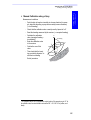
Important Recommendations
1. The 3011, Sagitta, Aquarius and Aquarius² receivers are highprecision navigation instruments. They should not however replace
the need for good judgment and careful navigation using traditional
methods.
2. Using and connecting 3011, Sagitta, Aquarius or Aquarius² to any
navigation peripheral does not make it less necessary for navigators
to be cautious and continually on the watch.
3. Like for any other GPS receiver, the performance of Aquarius and
Aquarius² is subject to the decisions of the US Department Of Defense, which has full control of the GPS. At any time the DOD can
decide to impair the precision and availability of the GPS signals
worldwide without the possibility for GPS users to claim for damages.
4. Magellan and its distributors shall not be liable for errors contained herein or for incidental consequential damages in connection
with the furnishing, performance, or use of this equipment.
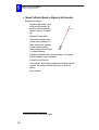
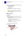
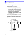
The 3011 GPS compass basically is a GPS receiver with the additional capability to perform heading measurements thanks to its
dual-sensor antenna. Like for any GPS receiver, the performance
level of the 3011 is closely tied to the conditions of GPS reception.
In the event of partial or complete reception loss, the 3011 will no
longer be able to perform heading measurements.
The loss of heading information, however brief it may be, is especially undesirable when the 3011 is connected to the automatic pilot.
For this reason, two possibilities are offered to cope with this possible event:
1. Dead reckoning (see page 173)
2. Using an external aid connected to the 3011 (see page 94).
Copyright Notice
Copyright © 2003-2006 Magellan Navigation Inc. All rights reserved.
Trademarks
All products and brand names mentioned in this publication are trademarks or registered trademarks of their respective holders.
Conventions used:
symbol indicates end of section.
MAGELLAN NAVIGATION PROFESSIONAL PRODUCTS - LIMITED WARRANTY
(NCSA)
Magellan Navigation warrants their GPS receivers and hardware accessories to be free of defects in material and
workmanship and will conform to our published specifications for the product for a period of one year from the
date of original purchase. THIS WARRANTY APPLIES ONLY TO THE ORIGINAL PURCHASER OF THIS
PRODUCT.
In the event of a defect, Magellan Navigation will, at its option, repair or replace the hardware product with no
charge to the purchaser for parts or labor. The repaired or replaced product will be warranted for 90 days from
the date of return shipment, or for the balance of the original warranty, whichever is longer. Magellan Navigation warrants that software products or software included in hardware products will be free from defects in the
media for a period of 30 days from the date of shipment and will substantially conform to the then-current user
documentation provided with the software (including updates thereto). Magellan Navigation's sole obligation
shall be the correction or replacement of the media or the software so that it will substantially conform to the
then- current user documentation. Magellan Navigation does not warrant the software will meet purchaser’s
requirements or that its operation will be uninterrupted, error-free or virus-free. Purchaser assumes the entire risk
of using the software.
PURCHASER’S EXCLUSIVE REMEDY UNDER THIS WRITTEN WARRANTY OR ANY IMPLIED
WARRANTY SHALL BE LIMITED TO THE REPAIR OR REPLACEMENT, AT MAGELLAN NAVIGATION’S OPTION, OF ANY DEFECTIVE PART OF THE RECEIVER OR ACCESSORIES WHICH ARE
COVERED BY THIS WARRANTY. REPAIRS UNDER THIS WARRANTY SHALL ONLY BE MADE AT
AN AUTHORIZED MAGELLAN NAVIGATION SERVICE CENTER. ANY REPAIRS BY A SERVICE
CENTER NOT AUTHORIZED BY MAGELLAN NAVIGATION WILL VOID THIS WARRANTY.
To obtain warranty service the purchaser must obtain a Return Materials Authorization (RMA) number prior to
shipping by calling 800-229-2400 (U.S.) or 408 615 3981 (International), or by sending a repair request on-line
at http://professional.magellangps.com/fr/contact/. The purchaser must return the product postpaid with a copy of
the original sales receipt to the address provided by Magellan Navigation with the RMA number. Purchaser’s
return address and the RMA number must be clearly printed on the outside of the package.
Magellan Navigation reserves the right to refuse to provide service free-of-charge if the sales receipt is not
provided or if the information contained in it is incomplete or illegible or if the serial number is altered or removed. Magellan Navigation will not be responsible for any losses or damage to the product incurred while the
product is in transit or is being shipped for repair. Insurance is recommended. Magellan Navigation suggests
using a trackable shipping method such as UPS or FedEx when returning a product for service.
EXCEPT AS SET FORTH IN THIS LIMITED WARRANTY, ALL OTHER EXPRESSED OR IMPLIED
WARRANTIES, INCLUDING THOSE OF FITNESS FOR ANY PARTICULAR PURPOSE, MERCHANTABILITY OR NON-INFRINGEMENT, ARE HEREBY DISCLAIMED AND IF APPLICABLE, IMPLIED
WARRANTIES UNDER ARTICLE 35 OF THE UNITED NATIONS CONVENTION ON CONTRACTS FOR
THE INTERNATIONAL SALE OF GOODS. Some national, state, or local laws do not allow limitations on
implied warranty or how long an implied warranty lasts, so the above limitation may not apply to you.
The following are excluded from the warranty coverage: (1) periodic maintenance and repair or replacement of
parts due to normal wear and tear; (2) batteries and finishes; (3) installations or defects resulting from installation; (4) any damage caused by (i) shipping, misuse, abuse, negligence, tampering, or improper use; (ii) disasters
such as fire, flood, wind, and lightning; (iii) unauthorized attachments or modification; (5) service performed or
attempted by anyone other than an authorized Magellan Navigations Service Center; (6) any product, components or parts not manufactured by Magellan Navigation; (7) that the receiver will be free from any claim for
infringement of any patent, trademark, copyright or other proprietary right, including trade secrets; and (8) any
damage due to accident, resulting from inaccurate satellite transmissions. Inaccurate transmissions can occur due
to changes in the position, health or geometry of a satellite or modifications to the receiver that may be required
due to any change in the GPS. (Note: Magellan Navigation GPS receivers use GPS or GPS+GLONASS to obtain
position, velocity and time information. GPS is operated by the U.S. Government and GLONASS is the Global
Navigation Satellite System of the Russian Federation, which are solely responsible for the accuracy and maintenance of their systems. Certain conditions can cause inaccuracies which could require modifications to the
receiver. Examples of such conditions include but are not limited to changes in the GPS or GLONASS transmis-
sion.) Opening, dismantling or repairing of this product by anyone other than an authorized Magellan Navigation Service Center will void this warranty.
MAGELLAN NAVIGATION SHALL NOT BE LIABLE TO PURCHASER OR ANY OTHER PERSON FOR
ANY INCIDENTAL OR CONSEQUENTIAL DAMAGES WHATSOEVER, INCLUDING BUT NOT LIMITED TO LOST PROFITS, DAMAGES RESULTING FROM DELAY OR LOSS OF USE, LOSS OF OR
DAMAGES ARISING OUT OF BREACH OF THIS WARRANTY OR ANY IMPLIED WARRANTY EVEN
THOUGH CAUSED BY NEGLIGENCE OR OTHER FAULT OFMAGELLAN NAVIGATION OR NEGLIGENT USAGE OF THE PRODUCT. IN NO EVENT WILL MAGELLAN NAVIGATION BE RESPONSIBLE
FOR SUCH DAMAGES, EVEN IF MAGELLAN NAVIGATION HAS BEEN ADVISED OF THE POSSIBILITY OF SUCH DAMAGES.
This written warranty is the complete, final and exclusive agreement between Magellan Navigation and the
purchaser with respect to the quality of performance of the goods and any and all warranties and representations.
This warranty sets forth all of Magellan Navigation’s responsibilities regarding this product. This limited warranty is governed by the laws of the State of California, without reference to its conflict of law provisions or the
U.N. Convention on Contracts for the International Sale of Goods, and shall benefit Magellan Navigation, its
successors and assigns.
This warranty gives the purchaser specific rights. The purchaser may have other rights which vary from locality
to locality (including Directive 1999/44/EC in the EC Member States) and certain limitations contained in this
warranty, including the exclusion or limitation of incidental or consequential damages may not apply.
--For further information concerning this limited warranty, please call or write:
Magellan Navigation, Inc., 960 Overland Court, San Dimas, CA 91773, Phone: +1 909-394-5000, Fax: +1 909394-7050 or
Magellan Navigation SA – ZAC La Fleuriaye – BP 433 – 44474 Carquefou Cedex – France Phone: +33 (0)2 28
09 38 00, Fax: +33 (0)2 28 09 39 39
MAGELLAN NAVIGATION PROFESSIONAL PRODUCTS LIMITED WARRANTY
(Europe, Middle East, Africa)
All Magellan Navigation global positioning system (GPS) receivers are navigation aids, and are not intended to
replace other methods of navigation. Purchaser is advised to perform careful position charting and use good
judgment. READ THE USER GUIDE CAREFULLY BEFORE USING THE PRODUCT.
1. MAGELLAN NAVIGATION WARRANTY
Magellan Navigation warrants their GPS receivers and hardware accessories to be free of defects in material and
workmanship and will conform to our published specifications for the product for a period of one year from the
date of original purchase or such longer period as required by law. THIS WARRANTY APPLIES ONLY TO
THE ORIGINAL PURCHASER OF THIS PRODUCT.
In the event of a defect, Magellan Navigation will, at its option, repair or replace the hardware product with no
charge to the purchaser for parts or labor. The repaired or replaced product will be warranted for 90 days from
the date of return shipment, or for the balance of the original warranty, whichever is longer. Magellan Navigation warrants that software products or software included in hardware products will be free from defects in the
media for a period of 30 days from the date of shipment and will substantially conform to the then-current user
documentation provided with the software (including updates thereto). Magellan Navigation's sole obligation
shall be the correction or replacement of the media or the software so that it will substantially conform to the
then- current user documentation. Magellan Navigation does not warrant the software will meet purchaser’s
requirements or that its operation will be uninterrupted, error-free or virus-free. Purchaser assumes the entire risk
of using the software.
2. PURCHASER’S REMEDY
PURCHASER’S EXCLUSIVE REMEDY UNDER THIS WRITTEN WARRANTY OR ANY IMPLIED
WARRANTY SHALL BE LIMITED TO THE REPAIR OR REPLACEMENT, AT MAGELLAN NAVIGATION’S OPTION, OF ANY DEFECTIVE PART OF THE RECEIVER OR ACCESSORIES WHICH ARE
COVERED BY THIS WARRANTY. REPAIRS UNDER THIS WARRANTY SHALL ONLY BE MADE AT
AN AUTHORIZED MAGELLAN NAVIGATION SERVICE CENTER. ANY REPAIRS BY A SERVICE
CENTER NOT AUTHORIZED BY MAGELLAN NAVIGATION WILL VOID THIS WARRANTY.
3. PURCHASER’S DUTIES
To obtain service, contact and return the product with a copy of the original sales receipt to the dealer from
whom you purchased the product.
Magellan Navigation reserves the right to refuse to provide service free-of-charge if the sales receipt is not
provided or if the information contained in it is incomplete or illegible or if the serial number is altered or removed. Magellan Navigation will not be responsible for any losses or damage to the product incurred while the
product is in transit or is being shipped for repair. Insurance is recommended. Magellan Navigation suggests
using a trackable shipping method such as UPS or FedEx when returning a product for service.
4. LIMITATION OF IMPLIED WARRANTIES
EXCEPT AS SET FORTH IN ITEM 1 ABOVE, ALL OTHER EXPRESSED OR IMPLIED WARRANTIES,
INCLUDING THOSE OF FITNESS FOR ANY PARTICULAR PURPOSE OR MERCHANTABILITY, ARE
HEREBY DISCLAIMED AND IF APPLICABLE, IMPLIED WARRANTIES UNDER ARTICLE 35 OF THE
UNITED NATIONS CONVENTION ON CONTRACTS FOR THE INTERNATIONAL SALE OF GOODS.
Some national, state, or local laws do not allow limitations on implied warranty or how long an implied warranty
lasts, so the above limitation may not apply to you.
5. EXCLUSIONS
The following are excluded from the warranty coverage:
(1) periodic maintenance and repair or replacement of parts due to normal wear and tear;
(2) batteries;
(3) finishes;
(4) installations or defects resulting from installation;
(5) any damage caused by (i) shipping, misuse, abuse, negligence, tampering, or improper use; (ii) disasters such
as fire, flood, wind, and lightning; (iii) unauthorized attachments or modification;
(6) service performed or attempted by anyone other than an authorized Magellan Navigations Service Center;
(7) any product, components or parts not manufactured by Magellan Navigation,
(8) that the receiver will be free from any claim for infringement of any patent, trademark, copyright or other
proprietary right, including trade secrets
(9) any damage due to accident, resulting from inaccurate satellite transmissions. Inaccurate transmissions can
occur due to changes in the position, health or geometry of a satellite or modifications to the receiver that may be
required due to any change in the GPS. (Note: Magellan Navigation GPS receivers use GPS or GPS+GLONASS
to obtain position, velocity and time information. GPS is operated by the U.S. Government and GLONASS is the
Global Navigation Satellite System of the Russian Federation, which are solely responsible for the accuracy and
maintenance of their systems. Certain conditions can cause inaccuracies which could require modifications to the
receiver. Examples of such conditions include but are not limited to changes in the GPS or GLONASS transmission.).
Opening, dismantling or repairing of this product by anyone other than an authorized Magellan Navigation
Service Center will void this warranty.
6. EXCLUSION OF INCIDENTAL OR CONSEQUENTIAL DAMAGES
MAGELLAN NAVIGATION SHALL NOT BE LIABLE TO PURCHASER OR ANY OTHER PERSON FOR
ANY INDIRECT, INCIDENTAL OR CONSEQUENTIAL DAMAGES WHATSOEVER, INCLUDING BUT
NOT LIMITED TO LOST PROFITS, DAMAGES RESULTING FROM DELAY OR LOSS OF USE, LOSS
OF OR DAMAGES ARISING OUT OF BREACH OF THIS WARRANTY OR ANY IMPLIED WARRANTY
EVEN THOUGH CAUSED BY NEGLIGENCE OR OTHER FAULT OF MAGELLAN NAVIGATION OR
NEGLIGENT USAGE OF THE PRODUCT. IN NO EVENT WILL MAGELLAN NAVIGATION BE RESPONSIBLE FOR SUCH DAMAGES, EVEN IF MAGELLAN NAVIGATION HAS BEEN ADVISED OF
THE POSSIBILITY OF SUCH DAMAGES.
Some national, state, or local laws do not allow the exclusion or limitation of incidental or consequential damages, so the above limitation or exclusion may not apply to you.
7. COMPLETE AGREEMENT
This written warranty is the complete, final and exclusive agreement between Magellan Navigation and the
purchaser with respect to the quality of performance of the goods and any and all warranties and representations.
THIS WARRANTY SETS FORTH ALL OF MAGELLAN NAVIGATION’S RESPONSIBILITIES REGARDING THIS PRODUCT.
THIS WARRANTY GIVES YOU SPECIFIC RIGHTS. YOU MAY HAVE OTHER RIGHTS WHICH VARY
FROM LOCALITY TO LOCALITY (including Directive 1999/44/EC in the EC Member States) AND CERTAIN LIMITATIONS CONTAINED IN THIS WARRANTY MAY NOT APPLY TO YOU.
8. CHOICE OF LAW.
This limited warranty is governed by the laws of France, without reference to its conflict of law provisions or the
U.N. Convention on Contracts for the International Sale of Goods, and shall benefit Magellan Navigation, its
successors and assigns.
THIS WARRANTY DOES NOT AFFECT THE CUSTOMER'S STATUTORY RIGHTS UNDER APPLICABLE LAWS IN FORCE IN THEIR LOCALITY, NOR THE CUSTOMER'S RIGHTS AGAINST THE
DEALER ARISING FROM THEIR SALES/PURCHASE CONTRACT (such as the guarantees in France for
latent defects in accordance with Article 1641 et seq of the French Civil Code).
--For further information concerning this limited warranty, please call or write:
Magellan Navigation SA – ZAC La Fleuriaye – BP 433 – 44474 Carquefou Cedex – France.
Phone: +33 (0)2 28 09 38 00, Fax: +33 (0)2 28 09 39 39
About this manual
This manual covers all the receivers from the Magellan marine survey product range, namely 3011 GPS Compass, Sagitta and Aquarius Series. It is split
into the following 18 sections.
Sections 1 to 3 provide all the information you need to operate an Aquarius
or Aquarius² receiver. Section 1 is about receiver description, section 2 about
installation and section 3 about how to get started with this type of receiver.
Section 4 (and 9) details all the possible position processing modes that can
be used in the Aquarius (and Sagitta) receivers, listing the requirements in
terms of hardware and software and explaining the basic way to implement
these modes from the TRM100 display screen.
Another way of implementing these modes, based on the use of $PDAS
commands, is also presented. This method is more particularly intended for
expert users.
Section 5 gives all the details of the processing modes specific to Aquarius².
This section uses a structure similar to Section 4.
Sections 6 to 8 provide the same type of information as the first three sections but this time for the Sagitta Series.
Sections 10 to 12 provide the same type of information as the first three sections but this time for the 3011GPS compass.
Section 13 guides you until you reach the desired operational status for your
receiver, assuming the installation and Getting Started phases have been
completed according to the instructions presented in the relevant sections
above.
In fact, this section describes all the functions of the TRM100. Basically, the
TRM100 is the front panel common to all Magellan marine survey receivers.
An important thing to know is that the TRM100 also comes as a software
program, called TRM100 PC Software - part of the standard supply. There is
however two additional functions in the TRM100 PC software allowing users to control the receiver directly via the set of available $PDAS commands
or, in the case of 3011 and Aquarius², to display heading measurements on a
compass rose.
Section 14 is an overview of the TRM100 PC Software. It tells you how to
connect the PC running this software to a receiver and how to use the Remote Display view. A thorough description of the Terminal view is also
provided. This view allows you to communicate with a receiver using
$PDAS commands (the only language understood by the receiver!).
Section 15 deals with the use of Sagitta or Aquarius at a reference station or
as a secondary mobile for which relative positioning is determined at a primary mobile. In these specific applications, a U-Link transmitter device has
to be used. This section gives all the details for connecting the U-Link
transmitter to a Sagitta or Aquarius. A full description of the data transmitted
by the U-Link device is provided. Multi-station operation is also discussed in
this section.
Section 16 describes the computed data outputs that can be enabled if you
use the receiver’s default configuration.
Section 17 describes the raw data outputs in ASCII format.
Section 18 describes the raw data outputs in binary format.
Section 19 is a compilation of all the $PDAS commands through which you
can control the configuration and operation of your receiver. Not all the
$PDAS commands can be applied to a given type of receiver. For example, it
makes sense to use the $PDAS commands relevant to heading measurements
in the 3011 or Aquarius² but not in the Sagitta or Aquarius. It is therefore
from a good knowledge of the receiver you are using that you will be able to
deduce the set of $PDAS commands that suits your receiver.
Section 20 discusses various topics for each of the receivers, such as special
procedures, specifications, accessories, etc.
Marine Survey Receivers
Table of Contents
Table of Contents
1.
Aquarius & Aquarius² - Equipment Description _____________ 1
Standard Supply ___________________________________________________ 1
Aquarius___________________________________________________________ 1
Aquarius²__________________________________________________________ 2
Firmware Options __________________________________________________ 3
Aquarius___________________________________________________________ 3
Aquarius²__________________________________________________________ 3
Aquarius² Upgrades ________________________________________________ 3
Aquarius & Aquarius² Hardware Options ________________________________ 4
Receiver _________________________________________________________ 6
Front Panel ________________________________________________________ 6
Rear Panel _________________________________________________________ 6
Receiver Bracket ___________________________________________________ 7
Description_________________________________________________________ 7
Table Mounting _____________________________________________________ 8
Ceiling Mounting ____________________________________________________ 8
Detachable TRM 100 Keypad/Display___________________________________ 9
NAP001 or NAP002 Antenna_________________________________________ 10
TRM 100 PC Software ______________________________________________ 11
UHF Radio Option _________________________________________________ 12
HF/MF Radio Option _______________________________________________ 12
Tx 4800 U-Link UHF transmission kit __________________________________ 12
2.
Aquarius & Aquarius² - Installation _____________________ 13
GPS Antenna _____________________________________________________ 13
Choosing a location where to install the antenna __________________________ 13
Antenna Mounting __________________________________________________ 15
Receiver ________________________________________________________ 16
Drilling Diagram____________________________________________________ 16
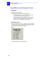
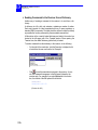
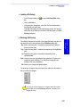
TRM100 PC Software ______________________________________________ 17
Computer Requirements _____________________________________________ 17
Installation Procedure _______________________________________________ 17
Rx 4812 U-LINK & Rx 1635 HM-LINK Options ___________________________ 18
Radio Antenna (UHF or HF/MF) ______________________________________ 18
Tx 4800 U-LINK Option_____________________________________________ 18
Connections Required in Typical Applications ___________________________ 19
3.
Aquarius & Aquarius² - Getting Started __________________ 21
Switching On/Off the Receiver _______________________________________ 21
Back-light Control & Screen Contrast Adjustments _______________________ 21
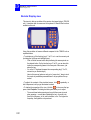
Data Screens _____________________________________________________ 22
Use Guidelines____________________________________________________ 24
i
Marine Survey Receivers
Table of Contents
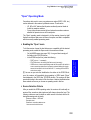
Common Tasks ____________________________________________________
Autonomous Processing Modes________________________________________
Processing modes implying the use of a data link _________________________
Particular Case of Heading Processing __________________________________
4.
24
24
25
25
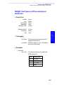
Aquarius Series - Processing Modes _____________________ 27
Introduction _____________________________________________________ 27
Modes Available____________________________________________________ 27
Primary and Backup Modes ___________________________________________ 27
Terminology Used __________________________________________________ 28
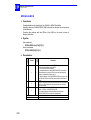
LRK Processing ___________________________________________________ 29
Precision Level _____________________________________________________
Specific Requirements _______________________________________________
Definitions ________________________________________________________
Configuration Guidelines _____________________________________________
Example #1 _______________________________________________________
Example #2 _______________________________________________________
Corrections Data Outputs ____________________________________________
29
29
30
31
32
34
35
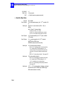
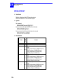
KART/EDGPS Processing____________________________________________ 36
Precision Levels ____________________________________________________
Specific Requirements _______________________________________________
Definitions ________________________________________________________
Configuration Guidelines _____________________________________________
Example #1 _______________________________________________________
Example #2 _______________________________________________________
Example #3 (EDGPS with NDS100 MkII station) __________________________
Corrections data outputs _____________________________________________
36
37
38
39
40
42
43
44
Relative Positioning Processing_______________________________________ 45
Definition _________________________________________________________
Primary Mobile Specific Requirements __________________________________
Secondary Mobile Specific Requirements ________________________________
Primary Mobile Configuration Guidelines_________________________________
Secondary mobile Configuration Guidelines ______________________________
Example __________________________________________________________
45
46
46
47
47
48
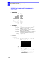
DGPS Processing __________________________________________________ 50
Precision Level _____________________________________________________
Specific Requirements _______________________________________________
Configuration Guidelines _____________________________________________
Example with external receiver/demodulator _____________________________
50
50
50
51
WAAS/EGNOS Processing ___________________________________________ 52
Precision Level _____________________________________________________
Definition _________________________________________________________
Specific Requirements _______________________________________________
Configuration Guidelines _____________________________________________
Example __________________________________________________________
52
52
52
52
53
GPS Processing ___________________________________________________ 54
Precision Level _____________________________________________________ 54
Specific Requirements _______________________________________________ 54
Configuration Guidelines _____________________________________________ 54
ii
Marine Survey Receivers
Table of Contents
Example __________________________________________________________ 54
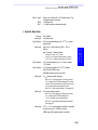
5.
Aquarius²-Only Processing Modes ______________________ 55
Introduction _____________________________________________________ 55
Heading Processing Principles _______________________________________ 56
Introduction _______________________________________________________
Determining the Baseline Length ______________________________________
Calibrating the heading measurement __________________________________
Need for calibration _________________________________________________
What is the calibration value? _________________________________________
When to perform or resume calibration? ________________________________
Manual Calibration along a Quay ______________________________________
Manual Calibration Based on Alignment with Seamarks _____________________
Automatic Calibration Computation while Navigating _______________________
56
57
58
59
59
60
61
62
63
Heading Processing Implementation __________________________________ 64
Specific Requirements _______________________________________________ 64
Configuration Guidelines _____________________________________________ 64
Example __________________________________________________________ 64
Multi-Mode Operation ______________________________________________ 65
6.
Sagitta Series - Equipment Description __________________ 67
Standard Supply __________________________________________________ 67
Firmware Options _________________________________________________ 67
Hardware Options _________________________________________________ 68
Sagitta Unit ______________________________________________________ 70
Description of the Control Panel _______________________________________ 70
Dimensions _______________________________________________________ 70
NAP001 or NAP002 Antenna_________________________________________ 71
TRM 100 PC Software ______________________________________________ 72
U-Link Radio Option _______________________________________________ 73
HM-Link Radio Option ______________________________________________ 73
Tx 4800 U-Link UHF transmission kit __________________________________ 73
TRM 100 Keypad/Display Option _____________________________________ 74
7.
Sagitta Series - Installation ___________________________ 75
GPS Antenna _____________________________________________________ 75
Choosing a location where to install the antenna __________________________ 75
Antenna Mounting __________________________________________________ 76
Sagitta Unit ______________________________________________________ 77
Drilling Diagram____________________________________________________ 77
Typical Setup with Rx 4812 U-Link Option Installed________________________ 78
TRM100 PC Software ______________________________________________ 79
Computer Requirements _____________________________________________ 79
Installation Procedure _______________________________________________ 79
Rx 4812 U-LINK & Rx 1635 HM-LINK Options ___________________________ 79
Radio Antenna (UHF or HF/MF) ______________________________________ 80
Tx 4800 U-LINK Option_____________________________________________ 80
iii
Marine Survey Receivers
Table of Contents
8.
Sagitta Series - Getting Started ________________________ 81
DC Power _______________________________________________________ 81
Switching on Sagitta is Automatic at Installation __________________________
Switching off Sagitta Manually ________________________________________
Switching on Sagitta after Intentional Power Removal______________________
An initialization Phase Takes Place after you Switch On the Sagitta ___________
81
81
81
82
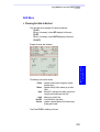
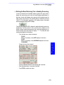
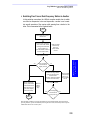
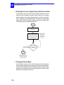
Checking that Operational Status is reached ____________________________ 82
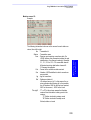
Using TRM100 as Control & Navigation Terminal ________________________ 84
Preliminaries ______________________________________________________ 84
Identification Screen ________________________________________________ 84
Data Screens ______________________________________________________ 85
9.
Sagitta Series - Processing Modes ______________________ 87
10. 3011 GPS Compass - Equipment Description ______________ 89
Standard Supply __________________________________________________ 89
Options _________________________________________________________ 89
3011 Processor ___________________________________________________ 90
Description of the Control Panel _______________________________________ 90
Dimensions _______________________________________________________ 90
NAP 011 Antenna _________________________________________________ 91
Description of the different parts ______________________________________ 91
Dimensions _______________________________________________________ 91
TRM 100 PC Software ______________________________________________ 92
TRM 100 Terminal Option___________________________________________ 93
HF/MF DGPS Reception Kit Option ____________________________________ 93
External Aid______________________________________________________ 94
11. 3011 GPS Compass - Installation _______________________ 95
NAP 011 Antenna _________________________________________________ 95
Choosing a location where to install the antenna __________________________
Possible Orientations ________________________________________________
Aid to Orientation __________________________________________________
Antenna Mounting __________________________________________________
Possible Types of Antenna Mounting ___________________________________
95
96
96
97
98
3011 Processor ___________________________________________________ 98
Drilling Diagram____________________________________________________ 98
Installation Examples _______________________________________________ 99
Interconnections __________________________________________________ 100
TRM100 PC Software _____________________________________________ 101
Computer Requirements ____________________________________________ 101
Installation Procedure ______________________________________________ 101
HF/MF Antenna __________________________________________________ 101
12. 3011 GPS Compass - Getting Started ___________________ 103
DC Power ______________________________________________________ 103
Switching on the 3011 is Automatic at Installation________________________ 103
iv
Marine Survey Receivers
Table of Contents
Switching off the 3011 Manually ______________________________________ 103
Switching On the 3011 after Intentional Power Removal ___________________ 103
An initialization Phase Takes Place after you Switch On the 3011 ____________ 104
Calibration ______________________________________________________ 105
Prerequisites _____________________________________________________ 105
Manual Calibration_________________________________________________ 106
Automatic Calibration Computation____________________________________ 108
TRM100 PC Software _____________________________________________ 110
Introduction ______________________________________________________
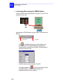
Connecting & Disconnecting the TRM100 Software _______________________
Working Environment ______________________________________________
Heading View_____________________________________________________
Remote Display View_______________________________________________
110
112
113
113
114
TRM100 Option Used as Navigation Terminal __________________________ 116
Identification Screen _______________________________________________ 116
Heading Screens __________________________________________________ 116
Outputs ________________________________________________________ 118
Introduction to the Configuration of the 3011 ___________________________ 118
Description of the Output Sentences __________________________________ 120
13. TRM100 PC Software Overview _______________________ 121
Purpose ________________________________________________________ 121
Connecting & disconnecting the TRM100 software ______________________ 123
Working Environment _____________________________________________ 124
Terminal view ___________________________________________________ 124
Basic Way of Sending a Command to the Receiver _______________________
Sending Commands to the Receiver from a Dictionary ____________________
Creating a New Dictionary___________________________________________
Making New Entries in a Dictionary____________________________________
Loading a Dictionary _______________________________________________
Revising a Dictionary _______________________________________________
Sending a series of commands from a text file___________________________
Color and Display Mode choices ______________________________________
Creating custom font colors _________________________________________
125
126
127
127
129
129
130
130
131
Remote Display view______________________________________________ 132
Recorder View ___________________________________________________ 133
Heading View ___________________________________________________ 134
14. Using TRM100 as Control & Navigation Terminal __________ 137
NAVIG Menu ____________________________________________________ 137
Viewing the Navigation Mode Currently Used ____________________________
Changing the Navigation Mode _______________________________________
Selecting the Homing or Bearing Mode_________________________________
Selecting the Profile Mode___________________________________________
Displaying the Data Specific to the Navigation Mode Used _________________
Using the Graphic Screen to Navigate _________________________________
137
137
138
139
141
144
DGNSS Menu____________________________________________________ 145
Entering the characteristics of one or more stations ______________________ 145
v
Marine Survey Receivers
Table of Contents
Listing the stations stored in the receiver _______________________________
Deleting or modifying the characteristics of a station______________________
Choosing the desired processing in the receiver _________________________
Monitoring the stations received ______________________________________
Messages ________________________________________________________
148
148
149
154
158
AUX Menu ______________________________________________________ 159
Choosing the Units to Be Used _______________________________________
Entering Local Time & Local/UTC Time Deviation ________________________
Choosing the Interface language _____________________________________
Initializing Position & Choosing a Coordinate System______________________
Changing the Minimum Elevation _____________________________________
Rejecting Satellites from the Processing ________________________________
Accessing the List of Output Messages _________________________________
Modifying an Output Message________________________________________
Adding an output message __________________________________________
Setting Raw Data Outputs___________________________________________
Changing Serial Port Settings ________________________________________
Determining the Baseline Length (Aquarius²) ___________________________
Calibrating the Heading Processing (Aquarius²) __________________________
Defining the Dead Reckoning Time in Heading Processing _________________
Viewing the visible GPS constellation __________________________________
Changing Speed Filtering ___________________________________________
Other functions ___________________________________________________
159
160
161
161
163
163
164
165
166
167
169
170
172
173
174
175
176
WPT-RTE Menu __________________________________________________ 177
Listing the Waypoints and Routes Stored in the Receiver __________________
Creating a waypoint _______________________________________________
Modifying/Deleting a Waypoint _______________________________________
Creating a Route __________________________________________________
Modifying/Deleting a Route__________________________________________
177
178
179
179
181
MARK Menu_____________________________________________________ 182
“Open” Operating Mode ___________________________________________ 183
Enabling the “Open” mode __________________________________________ 183
Source Selection Criteria ____________________________________________ 183
About the HM-Link Reception Kit ____________________________________ 184
Use Guidelines ____________________________________________________
Switching Over From a Dual-Frequency Station to Another _________________
Switching Over From a Single-Frequency Station to Another________________
Changing Frequency Band___________________________________________
184
185
186
186
LED Indicators on Inner Front Panel (Aquarius) ________________________ 187
Backup Option___________________________________________________ 188
What is the Backup Option? _________________________________________
How to check if the Backup Option is available? _________________________
Activating the Backup Mode _________________________________________
Selecting and Using the Backup Mode _________________________________
188
189
190
192
15. Using the U-Link Transmitter _________________________ 197
Introduction ____________________________________________________ 197
Additional Hardware Options Required _________________________________ 197
Optional Firmware Required _________________________________________ 197
vi
Marine Survey Receivers
Table of Contents
Transmitter Description ___________________________________________ 198
Connecting the Transmitter to Sagitta or Aquarius ______________________ 199
Setting Sagitta or Aquarius as a UHF Reference Station __________________ 200
Entering the Precise Coordinates of the Station __________________________ 200
Allowing the Station to Transmit its Corrections Data _____________________ 201
Checking the Corrections Generated by a Reference Station ________________ 202
Setting Sagitta or Aquarius as a Secondary Mobile ______________________ 203
Examples _______________________________________________________ 204
Transmitting Secondary Mobile _______________________________________ 204
Reference Station Transmitting Data in LRK Format ______________________ 204
Multi-Station Operation____________________________________________ 205
Transmitted Correction Data________________________________________ 206
Correction data string, general form ___________________________________
LRK Format Message _______________________________________________
Proprietary Pseudorange Corrections Message___________________________
L1 phase, C/A Code Message ________________________________________
RTCM Message ___________________________________________________
User Message ____________________________________________________
206
207
208
209
210
211
16. Computed Data Outputs _____________________________ 213
Conventions used ________________________________________________ 213
Sentence No. 1: $GPGGA __________________________________________ 214
Sentence No. 2: $GPGLL___________________________________________ 215
Sentence No. 3: $GPVTG __________________________________________ 215
Sentence No. 4: $GPGSA __________________________________________ 216
Sentences No. 5 (& 18 for Aquarius): $GPZDA _________________________ 216
Sentence No. 6: $GPRMC __________________________________________ 217
Sentence No. 7: $GPGRS __________________________________________ 218
Sentence No. 8: $GPGST __________________________________________ 218
Sentence No. 9: $GPGSV __________________________________________ 219
Sentence No. 10: $GPGMP _________________________________________ 220
Sentence No. 11: $GPHDT _________________________________________ 221
Sentence No. 12: $GPHDG _________________________________________ 221
Sentence No. 13: $GPROT _________________________________________ 221
Sentence No. 14: $GPVBW _________________________________________ 222
Sentence No. 15: $GPVHW_________________________________________ 222
Sentence No. 16: $GPOSD _________________________________________ 222
Sentence No. 17: $PDAS,HRP_______________________________________ 223
17. Raw Data Outputs in ASCII Format ____________________ 225
Notation rules ___________________________________________________ 225
L1 carrier quality indicator___________________________________________ 227
C/A code quality indicator ___________________________________________ 227
SVAR!D: Differential Data __________________________________________ 228
SVAR!R : Single-frequency GPS/WAAS/EGNOS pseudoranges in satellite time_ 236
vii
Marine Survey Receivers
Table of Contents
SVAR!R: Dual-frequency GPS pseudoranges in satellite time ______________ 238
SVAR!Q: Single-frequency GPS/WAAS/EGNOS pseudoranges in receiver time _ 241
SVAR!Q: Dual-frequency GPS pseudoranges in receiver time ______________ 243
SVAR!M: Event Time-Tagging_______________________________________ 246
SVAR!A: Almanac data ____________________________________________ 248
SVAR!E: Ephemeris data___________________________________________ 249
SVAR!U : Iono/UTC data___________________________________________ 250
SVAR!S : Health & A/S data ________________________________________ 251
SVAR!B: GPS Bit Flow _____________________________________________ 252
SVAR!W: WAAS/EGNOS Data _______________________________________ 254
SVAR!V: RELATIVE Mode Data ______________________________________ 256
18. Raw Data Outputs in SBIN Format _____________________ 259
Notation Rules___________________________________________________ 259
SBIN@R: Single-frequency GPS/WAAS/EGNOS pseudoranges in satellite time 261
SBIN@R: Dual-frequency GPS pseudoranges in satellite time______________ 263
SBIN@Q: Single-frequency GPS/WAAS/EGNOS pseudoranges in receiver time 266
SBIN@Q: Dual-frequency GPS pseudoranges in receiver time _____________ 268
SBIN@M: Event Time Tagging ______________________________________ 271
SBIN@A: Almanac data ___________________________________________ 273
SBIN@E: Ephemeris data __________________________________________ 273
SBIN@U: Iono/UTC data __________________________________________ 274
SBIN@S: Health & A/S data ________________________________________ 274
SBIN@b: GPS Bit Flow ____________________________________________ 275
SBIN@W: WAAS/EGNOS Data ______________________________________ 276
SBIN@V: RELATIVE Mode Data _____________________________________ 278
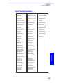
19. $PDAS Command Library ____________________________ 281
Introduction ____________________________________________________ 281
Command Format _________________________________________________ 281
Conventions Used _________________________________________________ 281
Command summary table__________________________________________ 282
$PDAS,AGECOR__________________________________________________ 284
$PDAS,ALTI_____________________________________________________ 285
$PDAS,ANTEN,DES _______________________________________________ 291
$PDAS,ANTEN,MOB ______________________________________________ 292
$PDAS,BITFLW __________________________________________________ 293
$PDAS,COMMNT _________________________________________________ 295
$PDAS,CONFIG __________________________________________________ 296
$PDAS,CONFIG,INIT ______________________________________________ 297
$PDAS,CONFIG,READ _____________________________________________ 298
$PDAS,CONFIG,RESET ____________________________________________ 299
$PDAS,DEFLT ___________________________________________________ 300
viii
Marine Survey Receivers
Table of Contents
$PDAS,DGPS,DELSTA _____________________________________________ 302
$PDAS,DGPS,MODE (E) ___________________________________________ 303
$PDAS,DGPS,MODE (R) ___________________________________________ 305
$PDAS,DGPS,STATION ____________________________________________ 307
$PDAS,DGPDAT__________________________________________________ 309
$PDAS,EVENT ___________________________________________________ 313
$PDAS,FILTER___________________________________________________ 315
$PDAS,FILTYP ___________________________________________________ 316
$PDAS,FIXMOD __________________________________________________ 317
$PDAS,FIXPAR __________________________________________________ 319
$PDAS,FIXTYP___________________________________________________ 320
$PDAS,FMT _____________________________________________________ 323
$PDAS,GEO _____________________________________________________ 324
$PDAS,GEODAT _________________________________________________ 326
$PDAS,GEOID,HEIGHT ____________________________________________ 327
$PDAS,GEOID,READ ______________________________________________ 329
$_GLL and $_GPQ,GLL ____________________________________________ 331
$PDAS,GNOS____________________________________________________ 332
$--GPQ,--- ______________________________________________________ 334
$PDAS,GPSDAT __________________________________________________ 336
$PDAS,HARDRS__________________________________________________ 338
$PDAS,HEALTH __________________________________________________ 339
$PDAS,HDGINI __________________________________________________ 340
$PDAS,HDGSET__________________________________________________ 341
$PDAS,HRP _____________________________________________________ 342
$PDAS,IDENT ___________________________________________________ 343
$PDAS,NAVSEL __________________________________________________ 347
$PDAS,OUTMES _________________________________________________ 348
$PDAS,OUTON and $PDAS,OUTOFF__________________________________ 350
$PDAS,PRANGE __________________________________________________ 351
$PDAS,PREFLL __________________________________________________ 353
$PDAS,PREFNE __________________________________________________ 354
$PDAS,QC ______________________________________________________ 355
$PDAS,RAZALM __________________________________________________ 357
$PDAS,SCREEN __________________________________________________ 358
$PDAS,SELGEO __________________________________________________ 359
$PDAS,SVDSEL __________________________________________________ 360
$PDAS,TR ______________________________________________________ 362
$PDAS,UNIT ____________________________________________________ 363
$_ZDA and $_GPQ,ZDA ___________________________________________ 364
20. Appendices _______________________________________ 365
ix
Marine Survey Receivers
Table of Contents
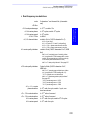
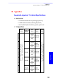
Aquarius & Aquarius² - Technical Specifications ________________________ 365
Main Features ____________________________________________________
Configurations ____________________________________________________
Performance Figures _______________________________________________
GPS/GNSS Characteristics ___________________________________________
Interfaces _______________________________________________________
Electrical ________________________________________________________
Environmental ____________________________________________________
Physical _________________________________________________________
365
365
366
366
367
367
367
367
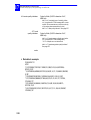
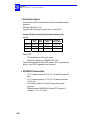
Aquarius & Aquarius² - Default Configuration __________________________ 368
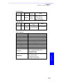
Sagitta Series - Technical Specifications_______________________________ 370
Main Features ____________________________________________________
Configurations ____________________________________________________
Performance Figures _______________________________________________
GPS/GNSS Characteristics ___________________________________________
Interfaces _______________________________________________________
Electrical ________________________________________________________
Environmental ____________________________________________________
Physical _________________________________________________________
370
370
370
370
371
371
371
371
Sagitta Series - Default Configuration ________________________________ 372
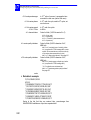
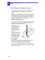
3011 GPS Compass - Calibration Principles ____________________________ 374
What is the calibration value? ________________________________________ 374
When to perform or resume calibration? _______________________________ 375
3011 GPS Compass - Calibration Procedures ___________________________ 376
Manual Calibration along a Quay _____________________________________ 376
Manual Calibration Based on Alignment with Seamarks ____________________ 377
Automatic Calibration Computation while Navigating ______________________ 378
3011 GPS Compass - Technical Specifications __________________________ 379
Performance Characteristics in Normal Conditions of Use __________________
GPS/GNSS Characteristics ___________________________________________
General Characteristics _____________________________________________
Interfaces _______________________________________________________
379
379
380
380
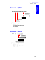
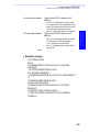
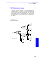
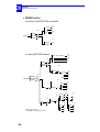
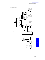
3011 GPS Compass - Connection to NT920 HDI unit_____________________ 381
3011 GPS Compass - Connection to MLR FX312 or FX412 GPS Receiver _____ 381
3011 GPS Compass - Available Geodetic Systems _______________________ 382
Systems List______________________________________________________ 382
Geodetic Parameters Used __________________________________________ 383
Power Supply Protections (All Receivers) ______________________________ 384
From Power Surges ________________________________________________ 384
From Voltage Drops________________________________________________ 384
From Current Surges _______________________________________________ 384
Connector Pinouts and Cables (All Receivers) __________________________ 385
AUX Connector ___________________________________________________
VGA Connector ___________________________________________________
Terminal Connector ________________________________________________
Port A (RS422)____________________________________________________
Port B (RS232)____________________________________________________
Port C (RS422)____________________________________________________
x
385
386
386
386
387
387
Marine Survey Receivers
Table of Contents
Port D (RS422) ___________________________________________________
Power In Connector________________________________________________
J6 388
1PPS Output _____________________________________________________
Event Input ______________________________________________________
Power Cord ______________________________________________________
RS232 / RS422 Serial Cord __________________________________________
Serial Cord _______________________________________________________
RS422 / RS232 Adaptor Cable________________________________________
DB15/DB9 RS232/RS422 Data Cable Option_____________________________
388
388
389
389
390
390
391
392
393
Radio Module Options _____________________________________________ 394
TRM100 Keypad/Display ___________________________________________ 395
Introduction to GNSS _____________________________________________ 395
GPS Constellation _________________________________________________
Signals __________________________________________________________
Navigation Message________________________________________________
GNSS ___________________________________________________________
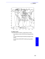
WAAS ___________________________________________________________
EGNOS __________________________________________________________
GEO current status (Jan 2002) _______________________________________
395
396
397
397
400
401
401
List of Possible Anomalies__________________________________________ 403
About the Three Configurations Stored in a Receiver ____________________ 404
TRM100 Functions Summary _______________________________________ 405
NAVIG Function ___________________________________________________
DGNSS Function __________________________________________________
AUX function _____________________________________________________
WPT-RTE Function_________________________________________________
MARK Function ___________________________________________________
405
406
407
408
408
Fix Quality Index _________________________________________________ 409
Sagitta Quick Start Leaflet _________________________________________ 411
Glossary
Index
xi
Aquarius & Aquarius² - Equipment Description
Standard Supply
Aquarius & Aquarius²
Equipment Description
1. Aquarius & Aquarius² - Equipment Description
(Magellan reserves the right to make changes to the list below without prior
notice.)
Standard Supply
Aquarius
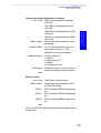
The Aquarius-01 (P0100751) or Aquarius-02 (P0100752) receiver is delivered in a ruggedized container in which the following items are provided:
-
1× Aquarius-01 or 02 unit - depending on purchase order - fitted with
a single GNSS sensor
-
1× GPS antenna NAP001 or NAP002 depending on purchase order
(NAP 001: P076311B; NAP 002: P0101158)
Firmware modules: RAWDAT, WAAS/EGNOS, KARTMODE,
USERGEOID, FASTOUTPUT
-
1× power cord, 2 meters (P0067035)
-
2× data cord, DB9 male / DB9 female, 2 meters (P0101243)
-
1× RS232/RS422 converter cable (P075675A)
-
-
1× TRM 100 unit (P0100722) consisting of the following:
- 1× detachable keypad/display terminal (P0100599), in fact
the receiver front panel
- 1× data cord, DB15 male/DB15 female, 1 meter (P0100688)
- 1× mounting bracket + knobs and screws (P0101297)
(Last two items used only if TRM100 detached from receiver to be used as remote unit.)
Mounting bracket for entire receiver (Aquarius + TRM100 unit)
-
1× User Manual (the present manual)
-
1× CD-ROM containing TRM 100 PC Software (for Windows
95/98/2000/NT) and User Manual in the form of PDF document.
1
1
Aquarius & Aquarius² - Equipment Description
Standard Supply
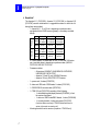
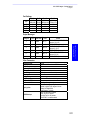
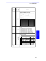
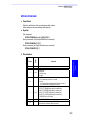
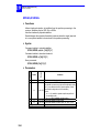
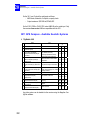
Aquarius²
The Aquarius²-11 (P0101385), Aquarius²-12 (P0101386) or Aquarius²-22
(P0101387) receiver is delivered in a ruggedized container in which the following items are provided:
-
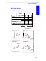
1× Aquarius²-11, 12 or 22 unit - depending on purchase order equipped with two GNSS sensors (primary + secondary; see table
below):
Secondary
Primary
Aquarius²-11
-
-
Aquarius²-22
Antenna
NAP 001
NAP 002
NAP 002
Sensor
L1 only,
16 channels
L1 only,
16 channels
L1, 16 channels
L2, 12 channels
Antenna
NAP 001
NAP 001
NAP 002
2× GNSS antenna, a combination of NAP 001 and NAP 002 antennas (see table above), depending on purchase order (NAP 001:
P076311B; NAP 002: P0101158)
Firmware modules:
- All receivers: RAWDAT, WAAS/EGNOS, KARTMODE,
USERGEOID, FASTOUTPUT
- Aquarius²-12 and 22 only: HEADING firmware
- Aquarius²-22 only: RELATIVE-OTF firmware
-
1× power cord, 2 meters (P0067035)
-
2× data cord, DB9 male / DB9 female, 2 meters (P0101243)
-
1× RS232/RS422 converter cable (P075675A)
-
1× TRM 100 unit (P0100722) consisting of the following:
- 1× detachable keypad/display terminal (P0100599), in fact
the receiver front panel
- 1× data cord, DB15 male/DB15 female, 1 meter (P0100688)
- 1× mounting bracket + knobs and screws (P0101297)
(Last two items used only if TRM100 detached from receiver to be used as remote unit.)
Mounting bracket for entire receiver (Aquarius + TRM100 unit)
-
2
Sensor
Aquarius²-12
L1 only,
L1, 16 channels L1, 16 channels
16 channels L2, 12 channels L2, 12 channels
Aquarius & Aquarius² - Equipment Description
Firmware Options
1× User Manual (the present manual)
-
1× CD-ROM containing TRM 100 PC Software (for Windows
95/98/2000/NT) and User Manual in the form of PDF document.
Aquarius & Aquarius²
Equipment Description
-
Firmware Options
Aquarius
-
LRKMODE (P0100893) (except for Aquarius-01)
RELATIVE OTF (P0101345)
REFSTATION (P077252A)
Aquarius²
-
LRKMODE (P0100893) (except for Aquarius²-11)
RELATIVE OTF (P0101345) (standard in Aquarius²-22)
REFSTATION (P077252A)
Aquarius² Upgrades
-
Aquarius²-12 to Aquarius²-22 (P0101509)
Aquarius²-11 to Aquarius²-12 (P0101510)
3
1
Aquarius & Aquarius² - Equipment Description
Aquarius & Aquarius² Hardware Options
Aquarius & Aquarius² Hardware Options
One of the following two options is necessary to operate Aquarius (Aquarius² needs two of them):
- GNSS Marine 30-meter cable kit (P076464A):
-
- 1× RG223 TNC-m/TNC-m coaxial cable, low loss, 30 m
long (C5050188)
- 1× marine mounting kit (P071448A) for NAP 00x antenna
GNSS Marine 10-meter cable kit (P0101393):
- 1× RG223 TNC-m/TNC-m coaxial cable, low loss, 10 m
long (C5050196)
- 1× marine mounting kit (P071448A) for NAP 00x antenna
Radio options available:
-
-
Rx 4812 U-Link UHF reception kit (P0101388) including 1× UHF reception module + coaxial cords for internal connections. Designed to
be embedded in Aquarius
Rx 1635 HM-Link HF/MF reception kit (P0101504) including HF/MF
radio receiver designed to be embedded in Aquarius
Tx 4800 U-Link UHF transmission kit (P0101389) including:
- 1× U-Link Tx 4812 transmitter module (with N female output
connector)
- 1× U-Link Tx 4812 interfacing box
- 1× RS422 data cable, 2 meters long
- 1× Power cable, 2 meters long
Antenna kits associated with radio options:
- UHF Marine 30-meter antenna kit (P0101390):
- 1× KX13 N-m/N-m coaxial cable, low loss, 30 meters long
(C5050168)
- 1× CXL70-3 dB UHF antenna, N-female connector + mounting parts:
Low band (400-430 MHz): C3310145
Medium band (420-450 MHz): C3310146
High band (440-470 MHz): C3310175
- 1× KX15 TNC-m/TNC-m coaxial cable (interfacing), 1 m
long (P05050156)
- 1× TNC-f/N-f adapter (C5050216)
4
Aquarius & Aquarius² - Equipment Description
Aquarius & Aquarius² Hardware Options
Aquarius & Aquarius²
Equipment Description
-
UHF Marine 10-meter antenna kit (P0101391):
- 1× KX13 N-m/N-m coaxial cable, low loss, 10 meters long
(P0101131)
- 1× CXL70-3 dB UHF antenna, N-female connector + mounting parts:
Low band (400-430 MHz): C3310145
Medium band (420-450 MHz): C3310146
High band (440-470 MHz): C3310175
- 1× KX15 TNC-m/TNC-m coaxial cable (interfacing), 1 m
long (P05050156)
- 1× TNC-f/N-f adapter (C5050216)
-
HF/MF Marine 30-meter antenna kit (P0101503):
- 1× DHM 5000 dual-band (HF/MF) antenna (P0100084)
- 1× marine mounting kit (P071448A) for DHM 5000 antenna
- 1× KX15 TNC-m/TNC-m coaxial cable, low loss, 30 m long
(C5050195)
- 1× antenna interface (P073815A)
-
HF/MF Marine 10-meter antenna kit (P0101505):
- 1× DHM 5000 dual-band (HF/MF) antenna (P0100084)
- 1× marine mounting kit (P071448A) for DHM 5000 antenna
- 1× KX15 TNC-m/TNC-m coaxial cable, low loss, 10 m long
(C5050196)
- 1× antenna interface (P073815A)
Miscellaneous:
- DB15/DB9 RS232/RS422 data cable, 2 m long (P0101587)
5
1
Aquarius & Aquarius² - Equipment Description
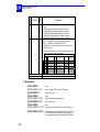
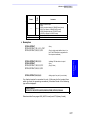
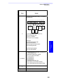
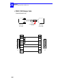
Receiver
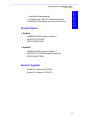
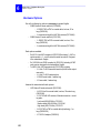
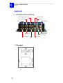
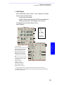
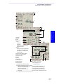
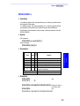
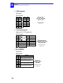
Receiver
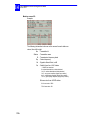
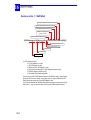
Front Panel
Receiver Front View
(After removing detachable TRM100 unit)
Receiver case
LED
indicating the
number of
received SVs
TRM100 Plug-In Unit
as front panel
Power LED
Sub D15C-f connector receptacle
(Used exclusively for connection to TRM100)
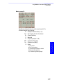
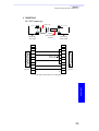
Rear Panel
1×RS422, Sub D9-f (Port A)
Output to VGA screen
External event input / 1 PPS Output
Control Push-Button
Aquarius
Aquarius²
1 or 2
Data Link
Inputs
1 or 2
Data Link
Inputs
GPS
Antenna
Input
2 GPS
Antenna
Inputs
F6: For future use
Power Input
1×RS232 (Port B)*
2×RS422 + 1PPS, Sub D15-f (Ports C & D)
* Used for connection to the PC running the TRM 100 PC Software
6
Aquarius & Aquarius² - Equipment Description
Receiver Bracket
Aquarius & Aquarius²
Equipment Description
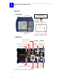
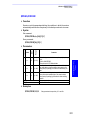
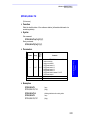
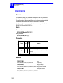
Receiver Bracket
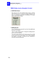
Description
The receiver bracket basically consists of two plates fixed together by two
knobs and two adjustable handles.
Rear Side
Inner plate
Knob
Front Side
Handle
Outer plate
Mechanical Specifications:
- Weight: 4 kg (8.82 lb)
-
Dimensions (H × W × P): 160 × 355 × 210 mm (6.30 × 13.40 × 8.27”)
Approximate space occupied by bracket + receiver in horizontal position: 175 × 345 × 305 mm (6.89 × 13.59 × 12.0”) (H × W × P)
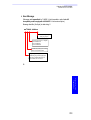
This bracket allows you to fix the receiver on a horizontal plane. Depending
on how the inner plate is positioned with respect to the outer plate, the receiver will be fixed from under the bracket (table mounting) or from above
(ceiling mounting).
Table Mounting
Ceiling Mounting
7
1
Aquarius & Aquarius² - Equipment Description
Receiver Bracket
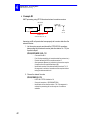
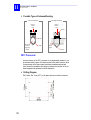
Table Mounting
The receiver can be secured on the bracket in one of the possible 6 positions, giving an angle to the receiver from 0° (horizontal) to + 30° or -20°,
depending on how you orientate the inner plate with respect to the outer
plate. Note that in the extreme two positions (+ 30° and -20°), allow for the
receiver case to come through the fixing plane.
Horizontal position is obtained when the handles are inserted in the 4th hole
(midpoint). Do not use the lower hole.
+30° position
Horizontal position
-20° position
Knob
Handle
To change the orientation of the receiver on the bracket, you must first remove the two handles, rotate the inner plate with respect to the outer plate
until you get the desired orientation. Then put back and tighten the handles.
The lever of each handle can then be oriented as desired by placing a
thumb at the end of the handle axis, pulling the handle and rotating the lever
until you get the desired position. Then let go.
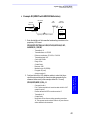
Ceiling Mounting
Same as previously except that the number of possible positions is limited
to 2: 0° (horizontal) and -10°. A higher tilt angle can be obtained if the receiver is allowed to rotate beyond (above) the fixing plane.
Horizontal position
Knob
Handle
8
-10° position
Aquarius & Aquarius² - Equipment Description
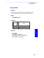
Detachable TRM 100 Keypad/Display
Aquarius & Aquarius²
Equipment Description
Detachable TRM 100 Keypad/Display
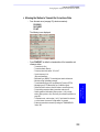
Bracket
This unit is in fact the receiver’s front panel. It is plugged to the receiver via
a single Sub D15-f connector. It is secured on the receiver case by means
of two screws located on either side of the unit.
When necessary, it can be detached from the receiver case to be used as a
remote unit. A bracket is provided to allow separate installation of the
TRM100 at maximum 1 meter from the receiver.
Before detaching the TRM100 from the receiver, TURN OFF the receiver.
Then, you just have to loosen and remove the central screw on either side
of the TRM100, as shown below:
You just have to
remove this screw
TURN OFF the receiver
before plugging or unplugging the TRM100!
Unplug the TRM100 gently from the receiver to avoid damaging the connector. (Please try to limit the number of times you have to plug or unplug
the TRM100 as this might end up damaging the connector).
Removing the TRM100 unit unveils the “inner front panel” of the receiver.
This panel is fitted with a Sub D15C-f connector receptacle, used for plugging the TRM100, and two LEDs. See page 177 for more information about
these LEDs.
Use the cable provided (P0100688) to link this unit to the receiver.
USE EXCLUSIVELY the connector receptacle on the inner front panel
to attach the TRM100 unit to the receiver!
Cable P0100688
9
1
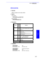
Aquarius & Aquarius² - Equipment Description
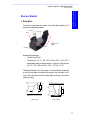
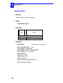
NAP001 or NAP002 Antenna
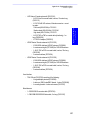
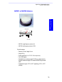
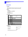
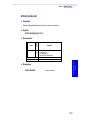
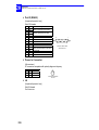
NAP001 or NAP002 Antenna
Phase center
2.4 cm
1.2 cm
TNC female
-
NAP 001: single-frequency version (L1)
NAP 002: dual-frequency version (L1/L2)
For both antennas:
- Diameter 143 mm, Height: 44 mm
- Weight: 342 g
- Power requirement: 5 to 13 V DC - 40 mA (via coax.)
- Gain: 39 dB approx.
- Admissible loss in antenna coaxial: 24 dB max., which means for
example a maximum length of 30 meters with RG223-type coaxial
cable
- Temperature ranges: -40°C to +65°C (operating); -40°C to +70°C
(storage).
10
Aquarius & Aquarius² - Equipment Description
TRM 100 PC Software
Aquarius & Aquarius²
Equipment Description
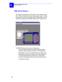
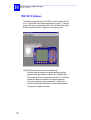
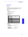
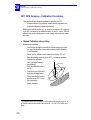
TRM 100 PC Software
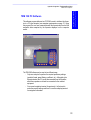
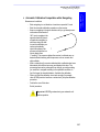
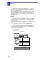
This software program delivered on CD-ROM is used to interface the Aquarius to a PC type computer (see computer requirements on page 17). Using
this program, the user can communicate with the Aquarius and have all the
navigation data computed by the Aquarius displayed on the computer
screen.
The TRM100 Software can be used in two different ways:
- Only as a setup tool to perform the required preliminary settings
(geodetic format, speed filtering coefficient, etc.). After getting the
Aquarius started, the PC can be disconnected from the Aquarius,
which then operates as a black box connected to the onboard
equipment
- Or as a real navigation terminal. As previously, it is first used to
make the required settings and then it is used as a display terminal
for navigation information.
11
1
Aquarius & Aquarius² - Equipment Description
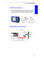
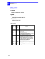
UHF Radio Option
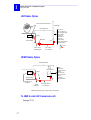
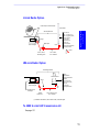
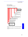
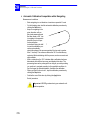
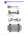
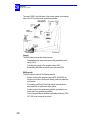
UHF Radio Option
Rx 4812 reception module inside Aquarius
UHF antenna
UHF Marine Antenna Kit
TNC type
TNC/N adapter
Data Link input
N type
Procom CXL 70-3:
Height: 1.3 m approx. (5.12”)
Weight: 1.2 kg approx. (2.65 lb)
Diameter, upper part:
16 mm (0.63”)
Diameter, lower part:
23 mm (0.9”)
Connector: N female
Mounted on mast using bracket
and U clamps provided:
Bracket
KX15, 1meter,
interfacing cable
KX13 cable,
10 or 30 meters
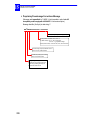
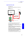
HF/MF Radio Option
HF/MF Marine Antenna Kit
HF/MF antenna
TNC type
Data Link input
TNC
type
Rx 1635 reception module
inside Aquarius
Antenna
Interface (1)
DHM5000
Combined Antenna
Dual-band: 270-330 kHz &
1.6-3.5 MHz
Height: 242 mm (9.53”)
Diameter: 136 mm (5.35”),
in lower part
TNC female plug
Separate ground terminal
KX15 cable, low loss
10 or 30 meters
(1) Minimizes interference (due to antenna cable) at data link input.
Tx 4800 U-Link UHF transmission kit
See page 137.
12
Aquarius & Aquarius² - Installation
GPS Antenna
2. Aquarius & Aquarius² - Installation
GPS Antenna
Aquarius & Aquarius²
Installation
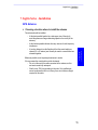
Choosing a location where to install the antenna
The antenna should be installed:
- At the best possible location for a wide-open view of the sky (to
avoid the presence of large obstructing objects in the vicinity of the
antenna)
- At the furthest possible distance from any sources of radio frequency
interference
- At such a distance from the Aquarius unit that the coaxial cable purchased (10 or 30 meters) can normally be used to connect these two
elements together.
Whenever possible, avoid exposing the antenna to smoke.
If for any reason the coaxial cable must be shortened:
- Do not cut the end of the cable connected to the antenna, as this
end must remain fully waterproof
- Wire the new TNC plug according to the rules. Only qualified personnel are allowed to do this. In theory, there is no minimum length
required for this cable.
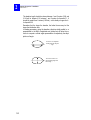
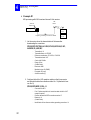
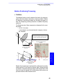
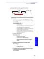
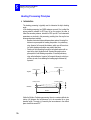
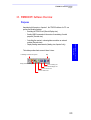
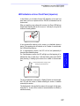
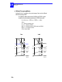
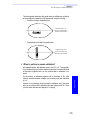
If two GNSS antennas are used for heading or Relative processing (Aquarius²), follow the same recommendations as above for the two antennas.
There is no need for mutual visibility between the two antennas. In heading
processing, the height deviation between the two antennas should form an
angle of ± 20° maximum for a given baseline length. See page 56.
Primary antenna
Secondary antenna
Baseline
13
2
Aquarius & Aquarius² - Installation
GPS Antenna
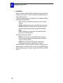
The baseline length should be chosen between 1 and 5 meters (3.28 and
16.4 feet) for Aquarius²-12, between 1 and 2 meters for Aquarius²-11. It
should be greater than 2 meters (6.56 feet) – with virtually no upper limit –
for Aquarius²-22.
Remember that the longer the baseline, the better the accuracy but the
longer the initialization time.
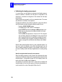
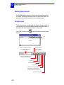
In heading processing, giving the baseline a direction strictly parallel to, or
perpendicular to the ship’s longitudinal axis (lubber line) will allow the receiver to compute a vertical angle representative of respectively the ship’s
pitch or roll angle.
The receiver can compute the
heading angle AND the pitch
angle
The receiver is able to compute the heading angle AND
the roll angle
14
Aquarius & Aquarius² - Installation
GPS Antenna
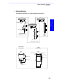
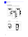
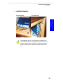
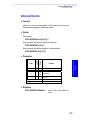
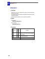
Antenna Mounting
Use the bracket provided in one of the configurations shown below.
Aquarius & Aquarius²
Installation
Antenna bracket
Two U-bolts
On horizontal mast
Diameter 56 mm (2.2”) max.
On flat
surface
On vertical mast
Diameter 56 mm (2.2”) max.
Antenna bracket
Mount dimensions
U-bolts
Mount dimensions
70 mm
(2.75”)
4 mm (0.16”)
62 mm
(2.44”)
4 mm (0.16”)
14 mm (0.55”)
44 mm (1.73”)
62 mm (2.44”)
48 mm (1.89”)
27.7 mm (1.1”)
15
2
Aquarius & Aquarius² - Installation
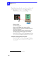
Receiver
Receiver
Choose the installation location taking account of the following:
- Desired location in cabin
- Location of third equipment the receiver must be attached to
- Lengths of coaxial cords to antennas
Allow for a clear space of about 25 dm3 (H200 × W345 × D350 mm) in the
cabin to install the receiver on its bracket.
The receiver should be mounted on its bracket using the 4 screws and
washers provided. Use an Allen wrench No. 4 to tighten the screws. Mount
the receiver on the bracket BEFORE mounting the bracket in the cabin.
The bracket should be secured on a horizontal plane in the cabin after drilling 4 holes in this plane (see drilling diagram below). Fix the bracket firmly
on the plane using 4 screws/nuts/washers (NOT PROVIDED).
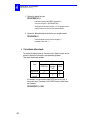
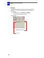
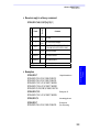
Drilling Diagram
Drill 4 holes, Diameter 5 mm (0.2”), in the plane where to mount the receiver
with its bracket.
Receiver Dimensions (top view): 245 × 305 mm (9.64 × 12”)
Bracket Dimensions (base plane): 170 × 273 mm (6.70 × 10.75”)
80 mm (3.15”)
Drill 4 holes
Dia. 5 mm (0.2”)
172 mm (6.77”)
16
140 mm (5.51”)
85 mm (3.35”)
Aquarius & Aquarius² - Installation
TRM100 PC Software
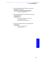
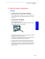
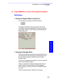
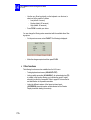
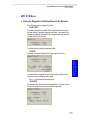
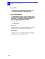
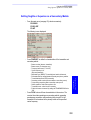
TRM100 PC Software
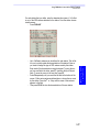
Computer Requirements
PC type computer
Operating system: Windows 95, 98, 2000, NT, XP
Unit: DX2-66 minimum, Pentium recommended
RAM: 16 MB minimum, 24 MB recommended
Space required on hard disk: 12.5 MB approx.
1 CD-ROM drive
1 RS232 serial port available
Aquarius & Aquarius²
Installation
-
Installation Procedure
-
-
Switch on the PC
Insert the TRM100 CD-ROM in the CD-ROM drive
From the Windows task bar, select Start>Run...
In the dialog box that opens, specify the path to the CD-ROM and
then type setup (example: type e:\setup) or browse on the CD-ROM
and choose the setup.exe file. Then click OK to start the installation
procedure
Follow the instructions provided on the screen to complete the installation process.
17
2
Aquarius & Aquarius² - Installation
Rx 4812 U-LINK & Rx 1635 HM-LINK Options
Rx 4812 U-LINK & Rx 1635 HM-LINK Options
Only trained personnel can install one of these reception modules, as this
requires opening the receiver case.
Radio Antenna (UHF or HF/MF)
The radio antenna should be installed:
- At such a distance from the Aquarius unit that the coaxial cable purchased (10 or 30 meters) can normally be used to connect these two
elements together.
- For a UHF antenna, at the highest possible location for best possible
reception
- For HF/MF antenna, at a location allowing connection of its ground
terminal to ship’s ground. This antenna does not necessarily need to
be located on top of a mast.
Tx 4800 U-LINK Option
See page 394.
18
Aquarius & Aquarius² - Installation
Connections Required in Typical Applications
Connections Required in Typical Applications
UHF antenna
NAP 001
or
NAP 002
DC Power Source (12 / 24 V DC)
Cable P0067035
Aquarius & Aquarius²
Installation
Aquarius-01 or -02
With Rx 4812 U-Link
Option Installed
Adapter C05050216
Cable C5050168 (30 m)
or P0101131 (10 m)
Interfacing Cable P05050156 (1 m)
Aquarius
Cable C5050196 (10 m)
or C5050188 (30 m)
UHF antenna
Aquarius²-12
With Rx 4812 U-Link
Option Installed
NAP 002
(Primary antenna)
DC Power Source (12 / 24 V DC)
Cable P0067035
Adapter C05050216
Cable C5050168 (30 m)
or P0101131 (10 m)
Interfacing Cable P05050156 (1 m)
Aquarius
NAP 001
(Secondary antenna)
Cable C5050196 (10 m)
or C5050188 (30 m)
Primary antenna ALWAYS connected to Input 1!
19
2
Aquarius & Aquarius² - Installation
Connections Required in Typical Applications
Aquarius²-22
With Rx 4812 U-Link & Rx 1635
HM-Link Options Installed
UHF antenna
HF/MF antenna
NAP 002
(Primary antenna)
Cable C5050168 (30 m)
or P0101131 (10 m)
Adapter C05050216
Interfacing Cable P05050156 (1 m)
Cable C5050195 (30 m)
or C5050196 (10 m)
Antenna Interface
(P073815A)
NAP 002
(Secondary antenna)
Aquarius
Cable C5050196 (10 m)
or C5050188 (30 m)
Cable P0067035
DC Power Source (12 / 24 V DC)
20
Aquarius & Aquarius² - Getting Started
Switching On/Off the Receiver
3. Aquarius & Aquarius² - Getting Started
Switching On/Off the Receiver
-
Depress
to switch on the receiver.
For about 5 seconds, the front panel screen first shows a few technical data about the receiver (BIOS used, copyright notice, etc.),
followed by a “System Initialization...” message (about 20 seconds).
Then an identification message is displayed (see example below) for
about 5 seconds:
Aquarius² example:
Aquarius & Aquarius²
Getting Started
The information provided allows full identification of the different
hardware and software parts used in the receiver. Use the Up and
Down keys to scroll through the list.
Then a data screen is displayed (see next page).
-
depressed for a few seconds
To switch off the receiver, keep
until a message on the screen confirms that the receiver is being
switched off.
Back-light Control & Screen Contrast Adjustments
-
operates as a toggle switch allowing you to alternatively turn on
and off the screen back-light. After switching on the receiver, the
back-light is automatically turned off before the end of initialization.
-
Adjust the screen backlight by holding down
Up or Down key.
-
Adjust the screen contrast by holding down
Left or Right key.
while pressing the
while pressing the
21
3
Aquarius & Aquarius² - Getting Started
Data Screens
Data Screens
After the initialization step, and following the display for about 5 seconds of
the receiver identification screen, the receiver will display one of the possible
4 data screens (see examples opposite) and will provide access to the main
menu in the lower part of the screen. To change data screen, press the Right
or Left key. The fourth data screen is accessible only if the Relative Positioning processing is enabled in the receiver.
1. From left to right:
1st line: Current Date, Position processing (i), Quality Index (ii), Number of Corrections
received and Age of Differential Corrections
2nd line: Current Local Time (UTC displayed if local time=UTC time), processing indicator
(iii), page indicator ("x/y" and "↔" displayed in turn), number of satellites used/received.
2.
4.
6.
8.
Current Position (latitude, longitude), computed.
3. Coordinate system used & altitude
Heading
5. Speed Over Ground
Course Over Ground
7. Rate of Turn
Pitch or roll angle, depending on how antennas
9. Longitudinal speed
are orientated.
10. Transverse speed
11. Baseline length
12. Altitude deviation between primary and secondary 13. Angle between True North and line
antennas.
passing through the phase centers
of the GNSS antennas.
(i) Processing used by the receiver to calculate position
-This field will display the name of the operating mode you chose as soon as the receiver is capable of
operating in this mode. Until this requirement is met, the field will flash at a low rate providing the name
of the currently running operating mode (i.e. "GPS", then "DGPS", etc.).
-If a backup mode is used, the "+" symbol will appear at the end of this field when the primary mode is
used AND the backup mode is potentially usable.
-If the receiver switches to the backup mode, the field will flash indicating the name of this mode.
- If the field flashes and ends with a "+", this means: 1)The receiver operates in backup mode, 2)The
conditions are restored to come back to the primary mode and 3)The receiver is waiting either for user
action to come back to the primary mode (if manual backup mode was selected) or the end of the userset time delay to switch back to the primary mode (if automatic backup mode was selected).
(ii) Fix Quality Index:
0-3: GPS
10-13: EDGPS
6-9: DGPS
14-19: Kinematic
(See also page 409)
If a backup mode is used, there are two quality indices displayed in this field, separated by the "/" symbol. The first quality index refers to the primary mode, the 2nd one to the backup mode.
(iii) Processing indicator:
“HDG”: Heading processing (flashing=result not available yet; On= heading result available)
“REL”: Relative processing (flashing=result not available yet; On= Relative result available)
“None”: No Heading or Relative processing enabled.
22
Aquarius & Aquarius² - Getting Started
Data Screens
Screen Examples:
1
2
3
4
5
6
2+3+5+6
4
8
6
Aquarius & Aquarius²
Getting Started
1
2+3
5
9
7
9
10
8
10
1
2+3
5
4
7
6
13
8
1
Relative Positioning Screen 5
11
12
23
3
Aquarius & Aquarius² - Getting Started
Use Guidelines
Use Guidelines
Common Tasks
Whatever the position-processing mode you intend to enable in your receiver, you will probably have to do one of the tasks listed below. All the
functions allowing these tasks to be performed are gathered in the AUX
menu. To use any of these functions refer to the page mentioned below with
the task.
- Choose the units used on the screen (see page 159)
- Check the local date & time (see page 160)
- Choose the language used on the screen (page 161)
- Enter/check the initial position and the coordinate system used (see
page 161)
- Enable/disable/modify the data messages available on the output
ports page 164)
- Check/modify the port settings (see page 167)
- Check/change the speed-filtering constant used (see page 175)
- Choose a navigation mode (see page 26)
- Miscellaneous (see other function in the AUX menu Chapter on page
159).
Autonomous Processing Modes
For any of these modes (GPS, WAAS/EGNOS, WADGPS + Relative for
Aquarius² only), you just need to do the following:
- Select and enable this mode through the DGNSS>MODE function (1st or
2nd row in the table; see page 149)
- On any of the data screens (see page 22), check that, after a certain
time, the receiver actually operates in the desired mode.
24
Aquarius & Aquarius² - Getting Started
Use Guidelines
Processing modes implying the use of a data link
Aquarius & Aquarius²
Getting Started
For these processing modes, you also have to do the following, using functions from the DGNSS menu:
- Enter the specifications of the data-transmitting source (station or
other) (see pages 145 and 148)
- Select and enable the desired processing mode; select the corrections data source defined previously to be involved in that processing
(see page 149)
- Check to see if the corrections data is properly acquired (see page
153)
- On any of the data screens (see page 22), check that, after a certain
time, the receiver actually operates in the desired mode.
Particular Case of Heading Processing
The heading processing is also a standalone-operating mode, but that can
only be implemented in Aquarius². To work in this mode, you need to do the
following:
- Select and enable this mode through the DGNSS>MODE function (see
page 149)
Then, using the AUX>INIT>HEADING function:
- Allow the receiver to determine the baseline length (see page 170)
- Once determined, validate this length in the receiver to allow it to perform heading measurements (page 170)
- LET THE RECEIVER DETERMINE THE HEADING
- Calibrate the heading measurements using one of the possible methods (page 172)
- Validate the offset angle resulting from the calibration.
The calibration result is stored to be part of the data present in the receiver configuration. Calibrating the heading measurement is required
when first installing the equipment on board, and then every time
changes are made in the equipment installation.
25
3
26
Aquarius & Aquarius² - Getting Started
Use Guidelines
Aquarius Series - Processing Modes
Introduction
4. Aquarius Series - Processing Modes
Introduction
Modes Available
The following processing modes are available in Aquarius:
- LRK processing
- KART/EDGPS processing
- RELATIVE POSITIONING processing. This mode allows you to accurately locate a receiver in relation to another. A radio link is
needed between the two receivers.
- DGPS processing
- WAAS/EGNOS processing (WADGPS)
- GPS processing.
Primary and Backup Modes
Sagitta & Aquarius
Processing Modes
To be sure your receiver can in all circumstances deliver the output data
you need, you can program a second processing mode to back up the
mode you have initially chosen for the receiver. Hence the following two
terms introduced now:
- Primary mode: the processing mode you choose as the mode to be
used in priority in the receiver
- Backup mode: the processing mode that backs up the primary mode,
which means this mode will be used, if it is operational, when the
primary mode fails.
You could for example program "LRK" using reference station "x" as the
primary mode and "LRK" using reference station "y" as the backup mode.
Obviously, you cannot program a backup mode if no primary mode has
been defined previously.
A very important thing to know is that from the moment you define a backup
mode, the receiver will always strive to operate in the primary mode, but
while doing this, it will make sure the backup mode is always operational in
the background, although actually not using it.
27
4
Aquarius Series - Processing Modes
Introduction
The way the receiver switches over to the backup mode is immediate when
the primary mode fails. Conversely, the way it switches back to primary –
when this mode regains its operational status– will conform to one of the following scenarios depending on which of them you chose earlier:
- Manual mode: The receiver will return to the primary mode only
when you select it manually. The position-processing indicator
shown at the top of any of the data screens (see page 22) will tell
you when the receiver can successfully come back to the primary
mode.
- Automatic mode: The primary mode will automatically be re-selected
after a user-set time delay.
Note that because the processing mode used as backup mode is characterized by a slower update rate (i.e. 5 sec.) compared to the primary mode,
there is more chance that its initialization time be longer.
Terminology Used
• Reference station: A stationary receiver, with accurately known location, that generates corrections data (5000 series receiver or later; see section 11).
The identification number of a reference station is user-defined through the $PDAS,UNIT command. In DGNSS processing mode, the mobile receiver will read this identification number from
the DGPS messages received to identify the source of corrections data.
• Beacon (or Transmitter or Transmitting station): A transmitting unit connected to one or more
reference stations. The beacon is used to transmit corrections data to users. A beacon is identified by a specific identification number, called Beacon Id, complying with the beacon numbering
rule defined by the RTCM. It is important to note that a reference station and the beacon to which
it is attached may have different identification numbers.
When defining a beacon, you will be asked to enter its geographical coordinates. Remember that
these coordinates do not need to be very precise as they are just used by navigators to select the
beacon the closest to their locations. On the contrary, the coordinates of a reference station must
be known with the best possible precision, as they are essential in generating corrections data.
• Navigator receiver: Mobile user receiver providing users with position or/and navigation data.
• Primary mobile: Navigator receiver given the capability to accurately determine the vector between its antenna position and that of a secondary mobile from which it receives corrections data
• Secondary mobile: Mobile receiver virtually operated as a reference station, i.e. transmitting
corrections data, so that the primary mobile can accurately determine the vector between its antenna position and that of the secondary mobile.
28
Aquarius Series - Processing Modes
LRK Processing
LRK Processing
Precision Level
-
Operating range up to 40 km (5 SVs or more) with OTF kinematic initialization
OTF initialization time: 30 seconds, typical
Precision:
In KR Fast Mode (20 Hz max. and 5-ms latency):
10 mm + 0.5 ppm, XY
20 mm + 1.0 ppm, Z
In KA Synchronous Mode (1 Hz and 1-s latency):
5 mm + 0.5 ppm, XY
10 mm + 1.0 ppm, Z
Performance figures are 1s RMS values measured in normal conditions of GPS reception (normal ionospheric activity,
5 satellites used and HDOP < 4) on clear site.
Specific Requirements
Receiver: Dual-frequency receiver type, Aquarius-02
Additional Hardware: Rx 4812 U-Link reception module (option) and UHF
antenna (see installation on page 18).
You can also use external equipment (such as GSM, radio modem, etc.) allowing
the acquisition of RTCM messages No. 3, 18 and 19 via one of the receiver ports.
Sagitta & Aquarius
Processing Modes
Additional Firmware: LRKMODE
Corrections Data: Pseudorange and phase measurements in LRK format
at 4800 Bd
You can also use RTCM messages No. 3, 18 and 19 received by external equipment attached to the receiver.
Possible Corrections Sources: Sagitta-02 or Aquarius-02 used at stations, 5002 SK stations from the previous series of marine survey products.
Any equipment transmitting corrections data in RTCM SC104 format if you intend
to work with an external receiver capable of receiving such data.
29
4
Aquarius Series - Processing Modes
LRK Processing
Definitions
LRK® is a kinematic processing method providing real-time positioning with
centimeter level precision. It can be implemented in dual-frequency receivers (Aquarius 02, 12 & 22).
To reduce the initialization time, and depending on the application, different
initialization modes are possible:
- OTF: ("On the Fly") Initialization with receiver in motion, start point
unknown
- STATIC: Initialization with receiver at a standstill, but point unknown
- Z-FIXED: Initialization with receiver in motion, start point unknown,
but receiver altitude remains constant throughout the initialization
phase
- POSIT: Initialization from a known point. This mode requires the
prior entry of a reference position.
Two different types of LRK solutions are available:
- LRK-A: (A for "Accurate") Accurate LRK position, computed every
time corrections data from the reference station is received (every
1.0 second in general)
- LRK-R: (R for "Real Time") LRK position, computed from extrapolated corrections data, available every 0.1 second.
Should the receiver be unable to produce a kinematic solution (during initialization phase or if insufficient amount of data), then an EDGPS solution
would be provided, every 0.1 second, in place of the LRK-A or LRK-R solution.
WLANE (Wide Lane): In this mode, the receiver works on the phase difference (L1 – L2) instead of working separately on the L1 & L2 phases as this
is done in LRK. Consequently, ambiguity resolution is easier and more reliable, but the precision is not so good as in LRK
WLANE can therefore be used as an alternative to the LRK mode in adverse operating conditions, and as far as the precision level then achievable
is still compatible with the user’s application. “WLANE” can be selected in
the USED column on the Mode screen (see page 150).
30
Aquarius Series - Processing Modes
LRK Processing
Configuration Guidelines
Use the DGNSS menu (see page 24) or use the TRM100 PC Software to
send the adequate commands to the receiver from the Terminal view (see
pages 123 and 124).
From the Terminal view, the following set of commands should be used:
• $PDAS,DGPS,STATION (page 307) to let the receiver know the
transmission specifications (carrier, modulation type, encryption) of each
of the potentially usable transmitters.
• $PDAS,DGPS,MODE (see page 305):
- To define your receiver as a corrections user
- To specify the corrections transmitter
- To specify the reference station(s) generating corrections.
• $PDAS,FIXMOD (page 316) to select the processing (LRK) and the
initialization mode used by the receiver.
• $PDAS,PREFLL or $PDAS,PREFNE to enter the known position from
which initialization will take place (only if you have chosen this initialization mode).
The following set of commands indirectly deals with this processing mode:
• $PDAS,DGPDAT (page 309) lets you define DGPS corrections outputs
• $PDAS,NAVSEL (page 347) lets you choose the type of position solution you want to use in your navigation application.
Sagitta & Aquarius
Processing Modes
31
4
Aquarius Series - Processing Modes
LRK Processing
Example #1
LRK processing with LRK format and internal U-Link receiver
UHF
antenna
(Built-in UHF
reception module)
Aquarius
Data Link
Proprietary pseudorange corrections at 4800 Bd
Transmitter
No. 8
Ref. Station
No. 14
1. Let the receiver know the characteristics of the transmitter
broadcasting the corrections:
$PDAS,DGPS,STATION,8,LA FLEUR,4716.52,N,00129.54,W, UHF,
444550000,30,,,4800,GN,2
-
Transmitter Id.: 8
Transmitter Name: LA FLEUR
Reference coordinates: 47°16.52’N, 1°29.54’W
Transmission band: UHF
Carrier: 444.55 MHz
Range: 30 km
(2 blank fields)
Baud rate: 4800
Modulation type: G (GMSK)
Encryption: N (none)
Antenna number (2)
2. Configure the built-in UHF reception module so that it can receive
and decode the data from reference station No. 14 (attached to beacon No. 8):
$PDAS,DGPS,MODE,1,D,R,8,,,14
-
32
Command line No.: 1
Port: D (allows acquisition of corrections data via built-in UHF
reception module)
Receiver defined as DGPS corrections receiver: R
Beacon Id.: 8
(2 blank fields)
Identification of the reference station generating corrections: 14
Aquarius Series - Processing Modes
LRK Processing
3. Select the LRK processing mode with OTF initialization:
$PDAS,FIXMOD,7,1,14
-
Fix mode: LRK, OTF initialization (7)
Source of corrections: LRK (1)
Identification of reference station used (14)
5. Choose the KART-A position solution for your navigation needs:
$PDAS,NAVSEL,3,1
-
Fix used for navigation: KART-A (3)
Navigation mode: none (1)
Sagitta & Aquarius
Processing Modes
33
4
Aquarius Series - Processing Modes
LRK Processing
Example #2
LRK processing using RTCM format and external corrections receiver
GPS antenna
Aquarius
Ext. receiver
Station
No. 710
Port B
RTCM-SC104
corrections data (3, 18, 19)
Assuming port B on Aquarius has been properly set to receive data from the
external receiver:
1. Let the receiver acquire and decode the RTCM-SC104 corrections
data provided by the external receiver (data from station No. 710) via
Aquarius’s B port:
$PDAS,DGPS,MODE,1,B,R,,,,710
-
Command line No.: 1
Port: B (allows acquisition of corrections data from external rec.)
Receiver defined as DGPS corrections receiver: R
(Next parameter (Beacon Id.) omitted to let the receiver acquire
corrections from the specified serial port (B))
Identification number of the reference station received: 710. If
this argument is omitted, all corrections will be acquired without
testing the reference station Id.
2. Choose the desired fix mode:
$PDAS,FIXMOD,7,1,710
-
34
LRK with OTF initialization: 7
Source of corrections: 1 (DGPS/KART/LRK)
Identification of the reference station: 710. If this argument is
omitted, the processing will use the only set of corrections
available.
Aquarius Series - Processing Modes
LRK Processing
Corrections Data Outputs
The corrections data received on the Data link input can be routed to a serial port for archival or post-processing purposes.
Four output formats are available:
Acquisition
format
Possible output formats
Proprietary
UHF
LRK
RTCM
SVAR!D
Proprietary UHF
LRK
RTCM
-
For example, to let the receiver output data on its B port, in immediate mode and LRK format, use the following command:
$PDAS,DGPDAT,1,B,3,,2
Sagitta & Aquarius
Processing Modes
35
4
Aquarius Series - Processing Modes
KART/EDGPS Processing
KART/EDGPS Processing
Precision Levels
Real-Time Centimeter KART Mode (RTK L1)
- Operating range up to 12 km (5 SVs or more) with OTF kinematic initialization
- OTF initialization time: 10 minutes, typical
- Precision:
In KR Fast Mode (20 Hz max. and 5-ms latency):
10 mm + 0.5 ppm, XY
20 mm + 1.0 ppm, Z
In KA Synchronous Mode (1 Hz and 1-s latency):
5 mm + 0.5 ppm, XY
10 mm + 1.0 ppm, Z
EDGPS
- No operational limits of distance
- Data convergence time: 2 minutes, typical
- Precision: 20 cm + 2 ppm, XYZ
Performance figures are 1s RMS values measured in normal conditions of GPS reception (normal ionospheric activity,
5 satellites used and HDOP < 4) on clear site.
36
Aquarius Series - Processing Modes
KART/EDGPS Processing
Specific Requirements
Receiver: Single-frequency receiver type, Aquarius-01
Additional Hardware: Rx 4812 U-Link reception module (option) and UHF
antenna (see installation on page 18).
You can also use external equipment (such as GSM, radio modem, etc.) allowing
the acquisition of RTCM messages No. 3, 18 and 19 via one of the receiver ports.
Additional Firmware: None (required firmware KARTMODE is provided as
standard)
Corrections Data: Pseudorange and phase measurements in LRK format
at 4800 Bd. In this case the LRK format may not contain any L2-related data
(but the data organization strictly remains that of the LRK format). In this
case, i.e. when there is no L2 data included, we sometimes refer to this data
string as being in “KART format”. Fundamentally, it is still in fact data transmitted in LRK format.
You can also use RTCM messages No. 3, 18 and 19 received by external equipment attached to the receiver.
EDGPS processing can specifically be obtained working with corrections data in
proprietary UHF format transmitted at 1200 Bd.
Possible Corrections Sources: Sagitta-01 or Aquarius-01 used at stations, 5001 SK stations from the previous series of marine survey products.
Dual-frequency stations would do the job as well.
Any equipment transmitting corrections data in RTCM SC104 format if you intend
to work with an external receiver capable of receiving such data.
Corrections data in proprietary UHF format transmitted at 1200 Bd comes exclusively from NDS100 MkII stations (former series of UHF stations).
Sagitta & Aquarius
Processing Modes
37
4
Aquarius Series - Processing Modes
KART/EDGPS Processing
Definitions
KART is a kinematic processing method providing real-time positioning with
centimeter level precision. It can be implemented in single-frequency receivers (Aquarius-01 & 11).
To reduce the initialization time, and depending on the application, different
initialization modes are possible:
- OTF: ("On the Fly") Initialization with receiver in motion, start point
unknown
- STATIC: Initialization with receiver at a standstill, but point unknown
- Z-FIXED: Initialization with receiver in motion, start point unknown,
but receiver altitude remains constant throughout the initialization
phase
- POSIT: Initialization from a known point. This mode requires the
prior entry of a reference position.
Two different solutions are available:
- KART-A : (A for "Accurate") Accurate KART position, computed
every time corrections data from the reference station is received
(every 1.0 second in general)
- KART-R: (R for "Real Time") KART position, computed from
extrapolated corrections data, available every 0.1 second.
Should the receiver be unable to produce a kinematic solution (during initialization phase or if insufficient amount of data), then an EDGPS solution
would be provided, every 0.1 second, in place of the KART-A or KART-R
solution.
38
Aquarius Series - Processing Modes
KART/EDGPS Processing
Configuration Guidelines
Use the DGNSS menu (see page 24) or use the TRM100 PC Software to
send the adequate commands to the receiver from the Terminal view (see
pages 123 and 124).
From the Terminal view, the following set of commands should be used:
• $PDAS,DGPS,STATION (page 307) to let the receiver know the
transmission specifications (carrier, modulation type, encryption) of each
of the potentially usable transmitters.
• $PDAS,DGPS,MODE (see page 305):
- To define your receiver as a corrections user
- To specify the corrections transmitter
- To specify the reference station(s) generating corrections.
• $PDAS,FIXMOD (page 316) to select the processing (KART) and the
initialization mode used by the receiver.
• $PDAS,PREFLL or $PDAS,PREFNE to enter the known position from
which initialization will take place (only if you have chosen this initialization mode).
The following set of commands indirectly deals with this processing mode:
• $PDAS,DGPDAT (page 309) lets you define DGPS corrections outputs
• $PDAS,NAVSEL (page 347) lets you choose the type of position solution you want to use in your navigation application.
Sagitta & Aquarius
Processing Modes
39
4
Aquarius Series - Processing Modes
KART/EDGPS Processing
Example #1
KART processing with LRK/KART format and with U-Link internal receiver
GPS antenna
(Built-in UHF
reception module)
UHF
antenna
Aquarius
Data Link
Pseudorange & phase LRK format at 4800 Bd
Transmitter
No. 8
Ref. Station
No. 14
1. Let the receiver know the characteristics of the transmitter
broadcasting the corrections:
$PDAS,DGPS,STATION,8,LA FLEUR,4716.52,N,00129.54,W, UHF,
444550000,30,,,4800,GN,2
-
Transmitter Id.:8
Transmitter Name: LA FLEUR
Reference coordinates: 47°16.52’N, 1°29.54’W
Transmission band: UHF
Carrier: 444.55 MHz
Range: 30 km
(2 blank fields)
Baud rate: 4800
Modulation type: G (GMSK)
Encryption: N (none)
Antenna number (2)
2. Configure the built-in UHF reception module so that it can receive
and decode the data from reference station No. 14 (attached to
transmitter No. 8):
$PDAS,DGPS,MODE,1,D,R,8,,,14
-
40
Command line No.: 1
Port: D (allows acquisition of corrections data via built-in UHF
reception module)
Receiver defined as DGPS corrections receiver: R
Transmitter Id.: 8
(2 blank fields)
Identification of the reference station generating corrections: 14
Aquarius Series - Processing Modes
KART/EDGPS Processing
3. Enter a reference position for KART initialization at a known point
(centimeter accuracy required):
$PDAS,PREFLL,0,4716.1043533,N,00129.4543000,W,48.752
-
Position: latitude, longitude, height
4. Select and initialize the KART processing mode from a known point,
using the data received:
$PDAS,FIXMOD,10,1,14
-
Fix mode: KART, initialization from known point (10)
Source of corrections: KART (1)
Identification of reference station used (14)
5. Choose the KART-R position solution for your navigation needs:
$PDAS,NAVSEL,1,1
-
Fix used for navigation: KART-R (1)
Navigation mode: none (1)
Sagitta & Aquarius
Processing Modes
41
4
Aquarius Series - Processing Modes
KART/EDGPS Processing
Example #2
KART processing using RTCM format and external corrections receiver
GPS antenna
Aquarius
Ext. receiver
Station
No. 710
Port B
RTCM-SC104
corrections data (3, 18, 19)
Assuming port B on Aquarius has been properly set to receive data from the
external receiver:
1. Let the receiver acquire and decode the RTCM-SC104 corrections
data provided by the external receiver (data from station No. 710) via
Aquarius’s B port:
$PDAS,DGPS,MODE,1,B,R,,,,710
-
Command line No.: 1
Port: B (allows acquisition of corrections data from external rec.)
Receiver defined as DGPS corrections receiver: R
(Next parameter (Beacon Id.) omitted to let the receiver acquire
corrections from the specified serial port (B))
Identification number of the reference station received: 710. If
this argument is omitted, all corrections will be acquired without
testing the reference station Id.
2. Choose the desired fix mode:
$PDAS,FIXMOD,28,1,710
-
42
KART with STATIC initialization: 28
Source of corrections: 1 (DGPS/KART/LRK)
Identification of the reference station: 710. If this argument is
omitted, the processing will use the only set of corrections
available.
Aquarius Series - Processing Modes
KART/EDGPS Processing
Example #3 (EDGPS with NDS100 MkII station)
GPS antenna
(Built-in UHF
reception module)
UHF
antenna
NDS100
MkII station
Aquarius
Transmitter
No. 8
Data Link
Proprietary UHF format at 1200 Bd
Ref. Station
No. 14
1. Enter the definition of the transmitter broadcasting corrections in the
proprietary UHF format:
$PDAS,DGPS,STATION,8,LA FLEUR,4716.52,N,00129.54,W, UHF,
444550000,30,,,1200,DN,1
-
Transmitter Id.: 8
Transmitter Name: LA FLEUR
Reference coordinates: 47°16.52’N, 1°29.54’W
Transmission band: UHF
Carrier: 444.55 MHz
Range: 30 km
(2 blank fields)
Baud rate: 1200
Modulation type: D (DQPSK)
Encryption: N (none)
Antenna number (1)
Sagitta & Aquarius
Processing Modes
2. Configure the built-in UHF reception module in order to let the receiver acquire and decode the corrections data generated by the
reference station used (in this example, station No. 14 used):
$PDAS,DGPS,MODE,1,D,R,8,,,14
-
Command line No.: 1
Port: D (allows acquisition of corrections data via built-in UHF
reception module)
Receiver defined as DGPS corrections receiver: R
Transmitter Id.: 8
(2 blank fields)
Identification of the reference station generating corrections:
14. This argument can be omitted if there is only one reference
station attached to the transmitter.
43
4
Aquarius Series - Processing Modes
KART/EDGPS Processing
3. Choose the desired fix mode:
$PDAS,FIXMOD,6,1,14
-
Kinematic processing with EDGPS initialization: 6
Source of corrections: 1 (DGPS/KART/LRK)
Identification of the reference station: 14. This argument can be
omitted if there is only one set of corrections available.
4. Choose the differential position solution for your navigation needs:
$PDAS,NAVSEL,1,1
-
Differential position solution used for navigation: 1
-
Navigation mode: none → 1
Corrections data outputs
The corrections data received on the serial port or Data link input can be
routed to a serial port for archival or post-processing purposes.
Three output formats are available:
Acquisition
Possible output formats
format
RTCM-SC104
LRK or
proprietary
UHF
SVAR!D
RTCM-SC104
LRK or proprietary UHF
-
For example, to let the receiver output DGPS data on its A port, in
time mode, every 10 seconds, in the SVAR!D format, use the following command:
$PDAS,DGPDAT,1,A,1,100,4
44
Aquarius Series - Processing Modes
Relative Positioning Processing
Relative Positioning Processing
Definition
This advanced function is used to determine the location of a remote secondary mobile (S) in relation to the location of a primary mobile (P). Relative
3D positioning is then achieved between the secondary and primary mobiles. The corresponding positioning information is available at the primary
mobile only.
The following two sets of three components are determined for the secondary mobile:
- ∆N, ∆E, ∆H, in meters
ρ (vector length, in m), φ (horizontal azimuth, in degrees), θ (site angle, in degrees)
True
North
∆N positive if Secondary located North of Primary
∆E positive if Secondary located East of Primary
∆H positive if Secondary higher than Primary
φ
P
∆N
∆E
As Reported on TRM100 screen:
(Example)
S
Line passing through
the antenna phase centers
(Top view)
ρ
Sagitta & Aquarius
Processing Modes
P
θ
∆H
S
∆H
ρ
φ
(Bearing, True)
Line passing through
the antenna phase centers
(Front view)
Basically, this processing type is implemented by configuring the secondary
mobile exactly as if it were virtually a reference station, although obviously
not stationary. This means that the secondary mobile transmits data in LRK
format via a radio link (typically UHF) and the primary mobile receives and
processes this data to deliver the above results.
45
4
Aquarius Series - Processing Modes
Relative Positioning Processing
Primary Mobile Specific Requirements
Hardware: Rx 4812 U-Link reception module (option) and UHF antenna
(see installation on page 18). You can also use external equipment (such as
GSM, radio modem, etc.) for the reception of GPS data in LRK format via
one of the receiver ports.
Firmware: In addition to standard firmware (DGPS, EDGPS, KARTMODE),
you need the following:
- RELATIVE OTF firmware
The precision obtained for Relative Positioning depends on the presence or
absence of the other firmware options:
- With standard firmware, you can only get “REL” processing, equivalent to KART in terms of precision
-
With LRK® firmware, you can get “REL” processing, equivalent to
LRK® in terms of precision.
Secondary Mobile Specific Requirements
Hardware: Tx 4800 U-Link transmission module (option) and UHF antenna
(see installation on page 18). You can also use external equipment (such as
GSM, radio modem, etc.) for the transmission of GPS data in LRK format
via one of the receiver ports.
Firmware: In addition to standard firmware (DGPS, EDGPS, KARTMODE),
you need the following options:
- LRKMODE (if dual-frequency), REFSTATION
46
Aquarius Series - Processing Modes
Relative Positioning Processing
Primary Mobile Configuration Guidelines
Use the DGNSS menu (see page 24) or use the TRM100 PC Software to
send the adequate commands to the receiver from the Terminal view (see
pages 123 and 124).
From the Terminal view, the following set of commands should be used for
the primary mobile:
• $PDAS,DGPS,STATION (page 307) to let the primary mobile know the
transmission specifications (carrier, modulation type, encryption) of the
secondary mobile.
• $PDAS,DGPS,MODE (see page 305):
- To define your receiver as a corrections user
- To specify the secondary mobile’s transmitter Id.
- To specify the secondary mobile’s station Id.
• $PDAS,FIXMOD (page 316) and $PDAS,FIXTYP to select the Relative processing in the primary mobile.
Secondary mobile Configuration Guidelines
Use the TRM100 PC Software to send the adequate commands to the receiver from the Terminal view (see pages 123 and 124) or use the DGNSS
menu (see page 24).
From the Terminal view, the following set of commands should be used for
the secondary mobile:
Sagitta & Aquarius
Processing Modes
• $PDAS,UNIT (page363) to define the identification number of the secondary mobile.
• $PDAS,DGPS,STATION (page 307) to define the transmission
specifications of the secondary mobile (carrier, modulation type,
encryption).
• $PDAS,DGPS,MODE (see page 305):
- To define the secondary mobile as a corrections generator
- To define the secondary mobile’s transmitter Id.
• $PDAS,PRANGE (page 351) to enable the receiver to output GPS
data in LRK format on the chosen port (port C or D for U-Link or another
port if another data link is used)
• $PDAS,FIXMOD to select “straight GPS mode” if the secondary is a
mobile (non-stationary) or “Single-station” if used as a stationary unit.
47
4
Aquarius Series - Processing Modes
Relative Positioning Processing
Example
UHF
antenna
(Built-in UHF
reception module)
Primary Mobile
Data Link
Proprietary
pseudorange
corrections at
4800 Bd
Tx 4800 ULink transm.
module No. 8
Secondary Mobile (unit No. 14)
Secondary:
1. Define its Unit Id.:
$PDAS,UNIT,14
-
Unit Number: 14
2. Define the transmission specifications of the transmitter attached to
the secondary mobile
$PDAS,DGPS,STATION,8,ESCORT,4716.52,N,00129.54,W, UHF,
444550000,30,,,4800,GN,2
(Transmitter position entered not involved in the process)
3. Ask the secondary mobile to transmit GPS data via port D:
$PDAS,DGPS,MODE,1,D,E,8,
-
Command line No.: 1
Output port for GPS data: D
Secondary mobile used as source of data: E (“E” for “emission”
or transmission)
Transmitter Id.: 8
antenna number (2)
4. Choose “straight GPS” as the fix mode and “LRK” as the type of
transmitted data:
$PDAS,FIXMOD,3
-
Straight GPS fix mode: 3 (you could choose any other fix mode)
5. Define the content of the data output on port D:
$PDAS,PRANGE, 1,D,1,10,7
-
48
Command line No.: 1
Output port for GPS data: D
Output mode: Time (1)
Output rate: 10 units of 0.1 s, or 1.0 s
Data type: SBIN@R Data in LRK format (7)
Aquarius Series - Processing Modes
Relative Positioning Processing
Primary:
1. Let the primary mobile know the characteristics of the transmitter
broadcasting data from the secondary mobile:
$PDAS,DGPS,STATION,8,ESCORT,4716.52,N,00129.54,W, UHF,
444550000,30,,,4800,GN,2
-
Transmitter Id.:8
Transmitter Name: ESCORT
(Transmitter position entered not involved in the process)
Transmission band: UHF
Carrier: 444.55 MHz
Range: 30 km
(2 blank fields)
Baud rate: 4800
Modulation type: G (GMSK)
Encryption: N (none)
Antenna number (2)
2. Configure the built-in UHF reception module so that it can receive
and decode the data from the secondary mobile, unit No. 14 (attached to transmitter No. 8):
$PDAS,DGPS,MODE,1,D,R,8,,,14
-
Command line No.: 1
Port: D (allows acquisition of corrections data via built-in UHF
reception module)
Receiver defined as DGPS corrections receiver: R
Transmitter Id.: 8
(2 blank fields)
Identification of the secondary mobile unit: 14
3. Select the RELATIVE processing mode:
Sagitta & Aquarius
Processing Modes
$PDAS,FIXTYP,1,P,,N,,80,1,14
-
Command line No.: 1
P: for Primary point
N: for normal direction of relative positioning (Secondary in relation to Primary)
Fix mode: RELATIVE (80)
Source of corrections: LRK (1)
Identification of secondary mobile (14)
$PDAS,FIXMOD,5,,1
-
Multi-mode processing (5)
Reference to FIXTYP command line number (1)
49
4
Aquarius Series - Processing Modes
DGPS Processing
DGPS Processing
Precision Level
Metric, depending on constellation status (GDOP, etc.).
Specific Requirements
Hardware: U-Link or HM-Link built-in reception module or external receiver/demodulator attached to Aquarius via one of its serial port
Firmware: Aquarius standard version (no additional firmware option required)
Corrections data: RTCM-SC104 data in “6 of 8” character format, 1200 or
4800 Bd, type 1, 2, 3, 9.
Configuration Guidelines
Use the DGNSS menu (see page 24) or use the TRM100 PC Software to
send the adequate commands to the receiver from the Terminal view (see
pages 123 and 124).
From the Terminal view, the following set of commands should be used:
• $PDAS,HARDRS (page 338) to set the receiver port attached to the
external demodulator
• $PDAS,DGPS,MODE (see page 305):
- To specify the port that the RTCM receiver is attached to
- To define your receiver as a corrections "consumer"
- To specify the identification of the reference station generating
the corrections.
• $PDAS,FIXMOD (page 316) to select the computation mode (singlestation DGPS) and the reference station used by the receiver.
The following set of commands indirectly deals with this processing mode:
• $PDAS,NAVSEL (page 347) lets you choose the type of position solution you want to use in your navigation application.
• $PDAS,AGECOR (page 284) lets you specify the maximum age permitted for corrections. Any corrections exceeding this age will be
discarded from the differential processing.
50
Aquarius Series - Processing Modes
DGPS Processing
Example with external receiver/demodulator
GPS antenna
Aquarius
Ext. receiver
Station
No. 710
Port B
RTCM-SC104
corrections data
Assuming port B on Aquarius has been properly set to receive data from the
external receiver:
1. Let the receiver acquire and decode the RTCM-SC104 corrections
data provided by the external receiver (data from station No. 710) via
Aquarius’s B port:
$PDAS,DGPS,MODE,1,B,R,,,,710
-
Command line No.: 1
Port: B (allows acquisition of corrections data from external rec.)
Receiver defined as DGPS corrections receiver: R
(Next parameter (Beacon Id.) omitted to let the receiver acquire
corrections from the specified serial port (B))
Identification number of the reference station received: 710. If
this argument is omitted, all corrections will be acquired without
testing the reference station Id.
2. Choose the desired fix mode:
$PDAS,FIXMOD,4,1,710
-
Single-station DGPS fix mode: 4
Source of corrections: 1 (DGPS/KART/LRK)
Identification of the reference station: 710. If this argument is
omitted, the processing will use the only set of corrections
available.
Sagitta & Aquarius
Processing Modes
-
3. Choose the differential position for your navigation needs:
$PDAS,NAVSEL,1,1
-
Differential position solution used for navigation: 1
-
Navigation mode: none → 1
4. For example, enter "40 seconds" as the maximum age not to be exceeded by the DGPS corrections received:
$PDAS,AGECOR,40
51
4
Aquarius Series - Processing Modes
WAAS/EGNOS Processing
WAAS/EGNOS Processing
Precision Level
-
-
Service area as defined for the system of satellites used. The different systems available are: WAAS in North America, EGNOS in
Europe and MSAS in Japan
Precision: 1 to 2 meters, XY - 3 meters, Z
Performance figures are 1s RMS values measured in normal conditions of GPS reception (normal ionospheric activity,
5 satellites used and HDOP < 4) on clear site.
Definition
This processing is used to refine the GPS position computed by the receiver, using the WADGPS corrections, and possibly the WAAS/EGNOS
pseudo-ranges, broadcast by a geostationary satellite (GEO) of the WAAS,
EGNOS or any other compatible SBAS system. Please, refer to pages 400
and 401 for more information about these systems.
Specific Requirements
Hardware: Aquarius standard version (no additional hardware option required)
Firmware: Aquarius standard version (no additional firmware option required)
Corrections data: from geostationary satellite, received on GPS reception
channel
Configuration Guidelines
Use the DGNSS menu (see page 24) or use the TRM100 PC Software to
send the adequate commands to the receiver from the Terminal view (see
pages 123 and 124).
From the Terminal view, the following set of commands should be used:
- $PDAS,GNOS to choose either automatic or manual selection of the
GEO to be received. If manual selection is chosen, this command
must also include the PRN of the GEO to be received.
- $PDAS,FIXMOD to enable the use of the WADGPS corrections in
the position processing
- $PDAS,SVDSEL to disable the use of WAAS/EGNOS pseudoranges
in the position processing
52
Aquarius Series - Processing Modes
WAAS/EGNOS Processing
The following set of commands indirectly deals with the implementation of a
WAAS/EGNOS processing:
- $PDAS,GEODAT to configure WAAS/EGNOS data outputs
- $PDAS,DGPDAT to configure DGPS data outputs
Example
GPS constellation
GEO No.120
GPS antenna
Aquarius
1. Enable the tracking of the WAAS or EGNOS system by specifying
the PRN number of the GEO used and choosing a selection mode
(Auto or Manual). Example:
$PDAS,GNOS,2,120
2: enables the tracking of WAAS/EGNOS and requests manual
selection of a GEO
120: is the GEO PRN (Inmarsat III F2-AOR-E)
Running this command will cause a WAAS/EGNOS-reserved
channel in the receiver to be allocated to SV PRN 120.
2. If needed, disable the use of the GEO pseudoranges in the position
processing:
$PDAS,SVDSEL,5,120
5: minimum elevation required of SVs (GPS & GEO) to be used
in the position processing
Sagitta & Aquarius
Processing Modes
120: is the PRN of the GEO from which pseudoranges should
be rejected
3. Enable the receiver to use the received WAAS/EGNOS data in the
position processing:
$PDAS,FIXMOD,4,2,120
4: selects “single-station DGPS” as the current GPS fix mode
2: selects WAAS/EGNOS to be the source of corrections
120: is the PRN of the GEO used
4. Choose the differential position solution for your navigation needs:
$PDAS,NAVSEL,1,1
-
WADGPS position solution used for navigation: 1
-
Navigation mode: none → 1
53
4
Aquarius Series - Processing Modes
GPS Processing
GPS Processing
Precision Level
5 m RMS, depending on constellation status (GDOP, etc.).
Specific Requirements
Hardware: Standard
Firmware: Aquarius standard version (no additional firmware option)
Corrections data: None required
Configuration Guidelines
Use the DGNSS menu (see page 24) or use the TRM100 PC Software to
send the adequate commands to the receiver from the Terminal view (see
pages 123 and 124).
From the Terminal view, the following set of commands should be used:
• $PDAS,FIXMOD (page 316) to select the computation mode (autonomous or “straight GPS).
• $PDAS,NAVSEL (page 347) lets you choose the type of position solution you want to use in your navigation application.
Example
GPS constellation
GPS antenna
Aquarius
1. Enable the “Straight” GPS processing in the receiver:
$PDAS,FIXMOD,3,0
3: selects “straight GPS” as current fix mode
0: deselects any possible source of corrections
2. Choose the straight GPS position solution for your navigation needs:
$PDAS,NAVSEL,1,1
-
54
GPS position solution used for navigation: 1
Navigation mode: none → 1
Aquarius²-Only Processing Modes
Introduction
Aquarius²-Only
Processing Modes
5. Aquarius²-Only Processing Modes
Introduction
The processing mode specific to Aquarius² is:
- The HEADING processing. This processing type is detailed on the
next pages.
In addition to the HEADING processing, Aquarius² offers the same processing modes as Aquarius, namely:
- LRK processing
- KART/EDGPS processing
- RELATIVE POSITIONING processing, only as standard in Aquarius²-22. With Aquarius² however, not only can this mode be
implemented between two remote receivers as explained for Aquarius on page 45, but also between two GNSS antennas, each being
connected to a specific GNSS input on the same Aquarius² receiver.
In this type of application, the Relative Positioning processing is
used for example to measure the baseline variations due to ship deformation or to monitor the movements of a mobile part on the ship
(a crane for example) with respect to any fixed point on the ship
structure.
- DGPS processing
- WAAS/EGNOS processing (WADGPS)
- GPS processing
55
5
Aquarius²-Only Processing Modes
Heading Processing Principles
Heading Processing Principles
Introduction
The heading processing is typically used to determine the ship’s heading
angle.
In the heading processing, two GNSS antennas are used. One is called the
primary antenna, attached to GPS input #1 on the receiver; the other is
called the secondary antenna, attached to GPS input #2. Two fundamental
parameters are involved in this processing, resulting from the way the two
antennas have been installed:
- Baseline: horizontal distance between phase centers. Knowing this
distance is a prerequisite for heading computation. In a preliminary
step, Aquarius² will compute this distance, which you will have to enter, before heading computation can actually take place
- Direction of the line passing through the two phase centers with respect to the ship’s longitudinal axis. Knowing this angle is also a
prerequisite for valid heading computation. In another preliminary
step, called calibration, Aquarius² will compute this angle, which you
will have to enter, thus validating the heading angle measured by
Aquarius².
NG
Secondary antenna
Primary antenna
Top View
Primary antenna
Secondary antenna
α
Side View
+
-
+
∆H
-
Baseline
Unlike the Relative Positioning processing, there is a maximum altitude deviation (∆H) between the two antennas not to be exceeded for a given
baseline length. The angle (α) formed by the two antennas in the vertical
plane should not exceed 20 °.
56
Aquarius²-Only Processing Modes
Heading Processing Principles
Aquarius²-Only
Processing Modes
Determining the Baseline Length
Knowing the baseline is essential if you want the receiver to be able to
make heading measurements.
The baseline can be determined as follows after enabling the Heading
processing in the DGNSS>MODE function:
- Select the AUX>INIT>HEADING function
- In the Length column, enter an estimate of the baseline length in the
Used cell
- Select F2-BASE and watch the Average and RMS parameters in the
Length column as time passes (time elapsed indicated on the right,
on top of the table).
Wait till the RMS value approaches or is equal to 0.00. The computed
value of baseline, displayed in the Average cell, is then assumed to
be valid.
- Select F3-STOP, and then F4-APPLY to enter the computed value as
the new Used value
- Select F5-OK to allow the receiver to compute the heading angle.
57
5
Aquarius²-Only Processing Modes
Heading Processing Principles
Calibrating the heading measurement
In a second step, once the baseline is determined and heading measurements are available, a calibration must take place to compensate for the
intentional or unintentional non-alignment of the antennas with the ship’s
horizontal axis.
Several methods are proposed to do this as described below. The reason
why calibration is necessary is also explained.
Computing the calibration value (offset) is achieved in a way much similar to
that of the baseline, provided a dynamic calibration method is used:
- Select the AUX>INIT>HEADING function
- In the Orient. column, enter “000.00” in the Used cell
- Select F3-OFFSET and watch the Average and RMS parameters in the
Orient. column as time passes (time elapsed indicated on the right,
on top of the table).
Wait till the RMS value approaches or is equal to 0.00. The computed
value of heading, displayed in the Average cell, is then assumed to be
valid. Compare this value to the known value provided by the conditions of calibration (see next pages). Calculate the difference (if it is
negative, see page 59), and then enter this difference into the Used
cell.
With the static (manual) method, there is no such computation phase. You
just have to enter the calibration value (offset) after deducing it from the
value of heading measured by Aquarius², once available, and from the exact value of heading in which the ship’s longitudinal axis is currently pointing
to.
About the height deviation between the two antennas:
When the heading processing is valid, Aquarius² also determines the angle
resulting from the baseline length and the height deviation between the two
antennas (angle ∝, as described on page 56). On the display screen, this
angle can be read in the Site column, Average row.
It is important to note that the value of the ∝ angle does not interfere with
the determination of the roll or pitch angle as the receiver automatically corrects its results for the value of this angle (if different from 0°).
58
Aquarius²-Only Processing Modes
Heading Processing Principles
The diagram opposite shows the angle actually measured by Aquarius². Obviously,
this angle depends on the orientation given
to the two GNSS antennas.
If the antennas are in a direction different
from that of the ship’s axis, which will necessarily be the case if you want that
Aquarius² also measures the roll angle, a
correction must be made to the measured
angle so that the receiver can provide the
true heading. Correcting the measured angle is achieved by entering a value, called
calibration value, into Aquarius².
Aquarius²-Only
Processing Modes
Need for calibration
N
Computed
heading
Primary GNSS
antenna
Secondary
GNSS antenna
What is the calibration value?
It is the deviation, observed BEFORE calibration, between the heading
computed by Aquarius² and the ship’s
true heading (see diagram below):
N
calibration value= computed heading – true heading
True heading
AFTER calibration, i.e. after having
entered the calibration value, Aquarius² can apply the correction to the
computed heading in such a way that:
Computed
heading
Aquarius² output heading = true heading
Primary
The calibration value can only be
positive. If a negative value is obtained, it must be transformed into a
Secondary
positive value by calculating its 360°’s
complement.
Example: In the above diagram, the true heading is 70 degrees. The computed heading is 160 degrees. Therefore, the calibration value is:
160 – 70 = 90°. Being positive, this value can be used directly.
On the other hand, if the obtained calibration value is for example – 24.5°,
the calibration value actually entered in Aquarius² will be its 360°’s complement, i.e. 360 – 24.5 = 335.5°.
59
5
Aquarius²-Only Processing Modes
Heading Processing Principles
The two diagrams below show the typical values of calibration as a function
of two typical orientations of the antennas with respect to the ship:
- Parallel to the ship’s longitudinal axis:
Calibration value= 0 ° or
close to 0° if there is some
uncertainty on the orientation
-
Perpendicular to the ship’s longitudinal axis:
Calibration value= 90 ° or
close to 90° if there is some
uncertainty on the orientation
When to perform or resume calibration?
At equipment delivery, the calibration value in Aquarius² is 0°. Consequently, if you are absolutely sure to have oriented the antennas in the
same direction as the ship’s longitudinal axis, you can conclude that no
calibration is required.
On the contrary, a calibration procedure will be necessary in ALL other
cases of orientation, whether you accurately know this orientation or not.
Likewise, if you accurately know the direction of the two antennas and in the
same time, you do not know which calibration value was entered in Aquarius², then you must check this value and change it if it is wrong.
There are two different methods possible for calibrating Aquarius²:
- Manual calibration (2 procedures: a static one and a dynamic one)
- Automatic calibration (a dynamic procedure).
60
Aquarius²-Only Processing Modes
Heading Processing Principles
Aquarius²-Only
Processing Modes
Manual Calibration along a Quay
Measurement conditions:
- Dock the ship to keep her immobile in a known direction (for example, align the ship along a quay with accurately known orientation)
(⇒ true heading).
- Check that the calibration value currently used by Aquarius² is 0°
-
-
Read the heading measured by the receiver (⇒ computed heading)
Calculate the calibration
N
value (computed heading –
1
True heading
true heading)
Enter the calibration value
in the receiver
Computed
heading
Confirm the use of this
Primary
value
Then check that the headSecondary
ing provided by Aquarius² is
now the true heading
End of procedure.
1 If it is negative, take the 360°’s complement to make it positive. If for example you get - 65° for
the calibration value, the actual calibration value will be 360° - 65°= 295°. If it is positive, use it
directly.
61
5
Aquarius²-Only Processing Modes
Heading Processing Principles
Manual Calibration Based on Alignment with Seamarks
Measurement conditions:
- Navigate to align the ship’s longitudinal axis with seamarks. By
definition, the resulting heading
Seamarks
followed is known (⇒ true heading)
- Navigate at constant speed
- Check that the calibration value
currently used by Aquarius² is 0°
- After a certain time of navigation
in these conditions, read the
heading measured by the receiver
(⇒ computed heading)
2
- Calculate the calibration value (computed heading – true heading)
- Enter the calibration value in the receiver
- Confirm the use of this value
- Then check that, with the ship’s longitudinal axis still aligned with the
seamarks, the heading provided by the receiver is now the true
heading.
End of procedure.
2
62
Same as previously if the calculated value is negative.
Aquarius²-Only Processing Modes
Heading Processing Principles
Aquarius²-Only
Processing Modes
Automatic Calibration Computation while Navigating
Measurement conditions:
- Start navigating in a set direction at a minimum speed of 4 knots
- Start the automatic calibration procedure on the receiver
- Keep on navigating in the given direction until you get steady measurements and then make a
180° turn to navigate in the
opposite direction (there is
no particular navigation instructions during the halfturn as the calibration procedure automatically
rejects this phase in the
process provided the turn
rate is greater than
1°/second). This maneuver allows the receiver to eliminate any undesired effects interfering with the process, such as currents and
ship’s attitude.
- After a certain time, the receiver indicates that a calibration has been
determined with sufficient accuracy and displays this value. The
processing time can be prolonged for as long as you wish providing
you continue to navigate according to the specified conditions. In
fact, the longer the traveled distance, the better the calibration
- When you think the calibration is accurate enough (for example
value of RMS precision less than a certain level), stop the calibration
procedure
- Confirm the use of this value
End of procedure.
Important: NEVER go astern during an automatic calibration operation.
63
5
Aquarius²-Only Processing Modes
Heading Processing Implementation
Heading Processing Implementation
Specific Requirements
Hardware: Standard, with two antennas
Firmware: Aquarius² standard version (no additional firmware option)
Corrections data: None required
Configuration Guidelines
Use the DGNSS menu (see page 24) or use the TRM100 PC Software to
send the adequate commands to the receiver from the Terminal view (see
pages 123 and 124).
From the Terminal view, the following set of commands should be used:
• $PDAS,FIXMOD to enable the heading processing, combined with a
position processing mode at your convenience
Example
GPS constellation
Aquarius²
Primary
GPS antenna
Secondary
GPS antenna
$PDAS,FIXMOD,43,0
-
64
Heading processing + standalone GPS fix mode
(0: Corrections data source=none)
Aquarius²-Only Processing Modes
Multi-Mode Operation
Aquarius²-Only
Processing Modes
Multi-Mode Operation
The table below summarizes the possible four cases of multi-mode operation in which two processing modes can be used concurrently.
Using external data (Proprietary
UHF or RTCM)
Standalone
Processing
Multi-Mode
Heading
Relative GPS WADGPS Relative
KART
DGPS EDGPS
OTF
OTF
or LRK
Position + Heading
•
•
•
•
•
Position + Relative
•
•
•
•
•
Heading + Relative
Heading (Rel) +
Relative
On Primary
Antenna
On Primary Antenna
Heading or Relative OTF processing
may be run simultaneously with one
of these 5 processing modes
Position + Heading
Heading + Relative
North
North
Heading
Heading
Fixed baseline
Fixed baseline
Primary
Data Link
Primary
Primary position computed
according to chosen processing
Position + Relative
Relative OTF
∆X, ∆Y, ∆Z
Remote
separate
system
Primary position not computed
Heading (Rel) + Relative
Relative OTF
∆X, ∆Y, ∆Z
Relative OTF
∆X, ∆Y, ∆Z
Variable baseline
Variable
baseline
Primary
Primary position computed
according to chosen processing
Data Link
Primary
Relative OTF
∆X, ∆Y, ∆Z
Primary position not computed
Remote
separate
system
65
5
66
Aquarius²-Only Processing Modes
Multi-Mode Operation
Sagitta Series - Equipment Description
Standard Supply
6. Sagitta Series - Equipment Description
Standard Supply
-
1× Sagitta-01 or 02 unit, depending on purchase order
-
1× GPS antenna NAP001 or NAP002 depending on purchase order
(NAP 001: P076311B; NAP 002: PO101158)
Firmware modules: RAWDAT, WAAS/EGNOS, EDGPSMODE,
USERGEOID, FASTOUTPUT
-
1× power cord, 2 meters (P0067035)
-
1× data cord, DB9 male / DB9 female, 2 meters (P0101243)
Fixing parts for receiver case (screws, washers, nuts)
-
1× User Manual (the present manual)
Sagitta Series
Equipment Description
The Sagitta-01 (P0100749) or Sagitta 02 (P0100750) receiver is delivered
in a non-reusable cardboard box. The following items are provided:
-
1× CD-ROM containing TRM 100 PC Software (for Windows
95/98/2000/NT) and User Manual in the form of PDF document
Magellan reserves the right to make changes to the above list without prior
notice.
Firmware Options
-
KARTMODE (P0100892)
LRKMODE (P0100893)
RELATIVE OTF (P0101345)
REFSTATION (P077252A)
67
6
Sagitta Series - Equipment Description
Hardware Options
Hardware Options
One of the following two options is necessary to operate Sagitta:
- GNSS Marine 30-meter cable kit (P076464A)
-
- 1× RG223 TNC-m/TNC-m coaxial cable, low loss, 30 m
long (C5050188)
- 1× marine mounting kit for NAP 00x antenna (P071448A)
GNSS Marine 10-meter cable kit (P0101393)
- 1× RG223 TNC-m/TNC-m coaxial cable, low loss, 10 m
long (C5050196)
- 1× marine mounting kit for NAP 00x antenna (P071448A)
Radio options available:
-
-
Rx 4812 U-Link UHF reception kit (P0101388) including 1× UHF reception module + 1× cord for internal coaxial connection. Designed
to be embedded in Sagitta
Rx 1635 HM-Link HF/MF reception kit (P0101504) including HF/MF
radio receiver designed to be embedded in Sagitta
Tx 4800 U-Link UHF transmission kit (P0101389) including:
- 1× U-Link Tx 4812 transmitter module (with N female output
connector)
- 1× U-Link Tx 4812 interfacing box
- 1× RS422 serial cable, 2 meters long
- 1× Power cable, 2 meters long
Antenna kits associated with radio options:
- UHF Marine 30-meter antenna kit (P0101390):
- 1× KX13 N-m/N-m coaxial cable, low loss, 30 meters long
(C5050168)
- 1× CXL70-3 dB UHF antenna, N-female connector + mounting parts:
Low band (400-430 MHz): C3310145
Medium band (420-450 MHz): C3310146
High band (440-470 MHz): C3310175
- 1× KX15 TNC-m/TNC-m coaxial cable (interfacing), 1 m
long (P05050156)
- 1× TNC-f/N-f adapter (C5050216)
68
Sagitta Series - Equipment Description
Hardware Options
-
UHF Marine 10-meter antenna kit (P0101391):
Sagitta Series
Equipment Description
- 1× KX13 N-m/N-m coaxial cable, low loss, 10 meters long
(P0101131)
- 1× CXL70-3 dB UHF antenna, N-female connector + mounting parts:
Low band (400-430 MHz): C3310145
Medium band (420-450 MHz): C3310146
High band (440-470 MHz): C3310175
- 1× KX15 TNC-m/TNC-m coaxial cable (interfacing), 1 m
long (P05050156)
- 1× TNC-f/N-f adapter (C5050216)
-
HF/MF Marine 30-meter antenna kit (P0101503)
- 1× DHM 5000 dual-band (HF/MF) antenna (P0100084)
- 1× marine mounting kit (P071448A) for DHM 5000 antenna
- 1× KX15 TNC-m/TNC-m coaxial cable, low loss, 30 m long
(C5050195)
- 1× antenna interface (P073815A)
-
HF/MF Marine 10-meter antenna kit (P0101505)
- 1× DHM 5000 dual-band (HF/MF) antenna (P0100084)
- 1× marine mounting kit (P071448A) for DHM 5000 antenna
- 1× KX15 TNC-m/TNC-m coaxial cable, low loss, 10 m long
(C5050196)
- 1× antenna interface (P073815A)
User Interface:
- TRM 100 unit (P0100722) consisting of the following:
- 1× keypad/display terminal (P0100599)
- 1× data cord, DB15 male/DB15 female, 1 meter (P0100688)
- 1× mounting bracket + knobs and screws (P0101297)
Miscellaneous:
-
1× RS232/RS422 converter cable (P075675A)
-
1× DB15/DB9 RS232/RS422 data cable, 2 m long (P0101587)
69
6
Sagitta Series - Equipment Description
Sagitta Unit
Sagitta Unit
Description of the Control Panel
To TRM 100 Terminal Option, if used
Output to VGA screen
Control Push-Button
Power LED
1 PPS Output
DGPS/DGNSS Input
GPS Antenna Input
1×RS232 (Port B)*
2×RS422 (Ports A & C)
Dimensions
70
LED indicating number
of received satellites
Power Input
Sagitta Series - Equipment Description
NAP001 or NAP002 Antenna
NAP001 or NAP002 Antenna
Sagitta Series
Equipment Description
Phase center
2.4 cm
1.2 cm
TNC female
-
NAP 001: single-frequency version (L1)
NAP 002: dual-frequency version (L1/L2)
For both antennas:
- Diameter 143 mm, Height: 44 mm
- Weight: 342 g
- Power requirement: 5 to 13 V DC - 40 mA (via coax.)
- Gain: 39 dB approx.
- Admissible loss in antenna coaxial: 24 dB max., which means for
example a maximum length of 30 meters with RG223-type coaxial
cable
- Temperature ranges: -40°C to +65°C (operating); -40°C to +70°C
(storage).
71
6
Sagitta Series - Equipment Description
TRM 100 PC Software
TRM 100 PC Software
This software program delivered on CD-ROM is used to interface the Sagitta to a PC type computer (see computer requirements on page 17). Using
this program, the user can communicate with the Sagitta and have all the
navigation data computed by the Sagitta displayed on the computer screen.
The TRM100 Software can be used in two different ways:
- Only as a setup tool to perform the required preliminary settings
(geodetic format, speed filtering coefficient, etc.). After getting the
Sagitta started, the PC can be disconnected from the Sagitta, which
then operates as a black box connected to the onboard equipment
- Or as a real navigation terminal. As previously, it is first used to
make the required settings and then it is used as a display terminal
for navigation information.
72
Sagitta Series - Equipment Description
U-Link Radio Option
U-Link Radio Option
Rx 4812 reception module inside Sagitta
UHF antenna
Sagitta Series
Equipment Description
UHF Marine Antenna Kit
TNC type
TNC/N adapter
Data Link input
N type
Procom CXL 70-3:
Height: 1.3 m approx. (5.12”)
Weight: 1.2 kg approx. (2.65 lb)
Diameter, upper part:
16 mm (0.63”)
Diameter, lower part:
23 mm (0.9”)
Connector: N female
Mounted on mast using bracket
and U clamps provided:
Bracket
KX15, 1meter,
interfacing cable
KX13 cable,
10 or 30 meters
HM-Link Radio Option
HF/MF Marine Antenna Kit
HF/MF antenna
TNC type
Data Link input
TNC
type
Rx 1635 reception module
inside Sagitta
Antenna
Interface (1)
DHM5000
Combined Antenna
Dual-band: 270-330 kHz &
1.6-3.5 MHz
Height: 242 mm (9.53”)
Diameter: 136 mm (5.35”),
in lower part
TNC female plug
Separate ground terminal
KX15 cable, low loss
10 or 30 meters
(1) Minimizes interference (due to antenna cable) at data link input.
Tx 4800 U-Link UHF transmission kit
See page 137.
73
6
Sagitta Series - Equipment Description
TRM 100 Keypad/Display Option
TRM 100 Keypad/Display Option
This option offers the same functions as the TRM 100 PC Software, but this
time from a dedicated hardware equipment (see below), called “TRM100
keypad/display Terminal” (or TRM100 unit), to which the Sagitta is attached.
Bracket
74
Sagitta Series - Installation
GPS Antenna
7. Sagitta Series - Installation
GPS Antenna
Choosing a location where to install the antenna
Sagitta Series
Installation
The antenna should be installed:
- At the best possible location for a wide-open view of the sky (to
avoid the presence of large obstructing objects in the vicinity of the
antenna)
- At the furthest possible distance from any sources of radio frequency
interference
- At such a distance from the Sagitta unit that the coaxial cable purchased (10 or 30 meters) can normally be used to connect these two
elements together.
Whenever possible, avoid exposing the antenna to smoke.
If for any reason the coaxial cable must be shortened:
- Do not cut the end of the cable connected to the antenna, as this
end must remain fully waterproof
- Wire the new TNC plug according to the rules. Only qualified personnel are allowed to do this. In theory, there is no minimum length
required for this cable.
75
7
Sagitta Series - Installation
GPS Antenna
Antenna Mounting
Use the bracket provided in one of the configurations shown below.
Antenna bracket
Two U-bolts
On horizontal mast
Diameter 56 mm (2.2”) max.
On flat
surface
On vertical mast
Diameter 56 mm (2.2”) max.
Antenna bracket
Mount dimensions
U-bolts
Mount dimensions
70 mm
(2.75”)
4 mm (0.16”)
62 mm
(2.44”)
4 mm (0.16”)
14 mm (0.55”)
44 mm (1.73”)
62 mm (2.44”)
48 mm (1.89”)
27.7 mm (1.1”)
76
Sagitta Series - Installation
Sagitta Unit
Sagitta Unit
As visual access to the Sagitta unit is not permanently needed, it can be
mounted inside a piece of furniture located in the cabin. However, allow for
easy access to the control panel, which may sometimes be required.
Also, choose the installation site taking into account the location of the onboard equipment the unit must be attached to.
The unit may be installed in horizontal or vertical position.
Drilling Diagram
Drill 4 holes, Dia. 7 mm (0.27”), in the plane where to mount the unit.
Sagitta Series
Installation
77
7
Sagitta Series - Installation
Sagitta Unit
Typical Setup with Rx 4812 U-Link Option Installed
Standard
VGA Monitor
UHF antenna
NAP 001
or
NAP 002
Sagitta unit
VGA AUX
A
B
C
Adapter C05050216
TRM
GPS
Data
link
Cable C5050168 (30 m)
or PO101131 (10 m)
Cable P0101243
Cable PO101243
RS232/RS422 converter
cable, P075675A (option)
Interfacing Cable P05050156 (1 m)
Cable C5050196 (10 m)
or C5050188 (30 m)
Cable P0067035
DC Power Source (12 / 24 V DC)
Use either of
these links to
connect Sagitta
to the PC running TRM100
Software
78
TRM100
PC
Software
TRM100
unit
Cable P0100688 (1 m)
Sagitta Series - Installation
TRM100 PC Software
TRM100 PC Software
Computer Requirements
-
PC type computer
Operating system: Windows 95, 98, 2000, NT
Unit: DX2-66 minimum, Pentium recommended
RAM: 16 MB minimum, 24 MB recommended
Space required on hard disk: 12.5 MB approx.
1 CD-ROM drive
1 RS232 serial port available
Sagitta Series
Installation
Installation Procedure
-
-
Switch on the PC
Insert the TRM100 CD-ROM in the CD-ROM drive
From the Windows task bar, select Start>Run...
In the dialog box that opens, specify the path to the CD-ROM and
then type setup (example: type e:\setup) or browse on the CD-ROM
and choose the setup.exe file. Then click OK to start the installation
procedure
Follow the instructions provided on the screen to complete the installation process.
Rx 4812 U-LINK & Rx 1635 HM-LINK Options
Only trained personnel can install one of these reception modules, as this
requires the opening of the receiver case.
79
7
Sagitta Series - Installation
Radio Antenna (UHF or HF/MF)
Radio Antenna (UHF or HF/MF)
The radio antenna should be installed:
- At such a distance from the Sagitta unit that the coaxial cable purchased (10 or 30 meters) can normally be used to connect these two
elements together.
- For a UHF antenna, at the highest possible location for best possible
reception
- For HF/MF antenna, at a location allowing connection of its ground
terminal to ship’s ground. This antenna does not necessarily need to
be located on top of a mast.
Tx 4800 U-LINK Option
See page 137.
80
Sagitta Series - Getting Started
DC Power
8. Sagitta Series - Getting Started
DC Power
Switching on Sagitta is Automatic at Installation
When you apply the power voltage to the Sagitta via the power cord, the
Power LED (green) lights up straight away indicating that the Sagitta unit is
now on.
Switching off Sagitta Manually
(Without unplugging the power cord)
Using a sharp tool, depress the control push-button for about 2 seconds.
Power removal is effective after a few seconds.
Sagitta Series
Getting Started
If the push-button is released before power is actually removed, the Power
LED will flash until power removal is effective.
If the push-button is released after power is removed, the Power LED will directly change from the permanently lit state to the off state.
Switching on Sagitta after Intentional Power Removal
Using the same tool as previously, depress briefly the control push-button.
The Power LED (green) will light up straight away indicating that the Sagitta
unit is now on.
81
8
Sagitta Series - Getting Started
Checking that Operational Status is reached
An initialization Phase Takes Place after you Switch On
the Sagitta
A few seconds after switching on the Sagitta, an initialization phase is
started. This operating state is indicated on the “Number of received satellites” LED which then lights up.
For a single-frequency receiver, this LED will be held permanently lit
throughout the initialization phase.
For a dual-frequency receiver, the LED will light up at the beginning of initialization but after a certain time, it will start blinking (with equal ON/OFF
times) denoting L1 tracking by the receiver for a number of received satellites.
Denotes Initialization Phase in Progress
The Sagitta does not generate any output message throughout
the initialization phase. Queries cannot either be addressed
from the TRM100.
The end of initialization is denoted by a flashing “Number of received satellites” LED with the number of flashes reflecting the number of satellites
received by the Sagitta.
This flashing state is the sign that the Sagitta will soon reach its fully operational state, i.e. as soon as the number of received satellites is sufficient (4
satellites minimum).
Checking that Operational Status is reached
As mentioned above, basically the operational status is reached when the
“Number of received satellites” LED produces a series of minimum 4 flashes
reflecting the number of received satellites. The series of n flashes are
separated by relatively longer OFF states. This should result in valid data on
the TRM100 or on any other navigation terminal attached to the receiver.
82
Sagitta Series - Getting Started
Checking that Operational Status is reached
At this stage, the “Getting started” phase is assumed to be finished.
If however you wish to have a closer look in the receiver to know exactly
how it operates, which type of position solution is computed, which results
are available on the output ports, which units are used, etc., and to be able
to make changes to some of these parameters, we recommend the use of
TRM100, either in its software or hardware version:
- Software version (standard delivery): TRM100 PC Software
- Hardware version (option): TRM100 keypad/display unit.
Sagitta Series
Getting Started
With TRM100 Software, you can work on your receiver in two different
ways:
- Via interactive display based on menus and parameter screens
(Remote Display View). What can be done with this display is fully
described in the Using TRM100 as Control & Navigation Terminal
section on page 137. To know how to use the Remote Display View,
refer to the Remote Display view section on page 132. Alternately,
the interactive display can be used as Navigation terminal.
- In command mode (Terminal view). This mode allows you to communicate with the receiver through $PDAS commands. If you are
familiar with these commands, you may wish to use them rather than
work with the Interactive Display (although the latter is more userfriendly). To send $PDAS commands to the receiver, refer to page
124. $PDAS commands are described in Section 19, Command Library.
With the TRM100 keypad/display unit, you can only work on the receiver via
interactive display, not in command mode. What can be done with the
TRM100 unit is fully described in the Using TRM100 as Control & Navigation Terminal section on page 137. Alternately, the interactive display can
be used as Navigation terminal. Note that the Remote Display view of the
TRM100 PC Software is in fact an emulation of the TRM100 keypad/display
unit.
If you start working with the default Sagitta configuration unchanged (see
description on page 368), none of the preset output messages will be enabled. To enable the desired messages, use TRM100 (see page 164) or
use $PDAS,OUTMES (see page 348). ♣
83
8
Sagitta Series - Getting Started
Using TRM100 as Control & Navigation Terminal
Using TRM100 as Control & Navigation Terminal
Preliminaries
(Read context of use on page 82).
The TRM100 should be connected to the receiver as follows:
- TRM100 keypad/display: connect the TRM100 unit to the receiver
via its TRM connector, using the serial cable provided
- TRM100 “software” version: use an RS232 line to connect the PC
running the TRM100 PC Software to the receiver (use port B for example, or port A via an RS232/RS422 converter cable).
Identification Screen
When starting Sagitta and TRM100, an identification message is displayed
on the screen. The information provided allows full identification of the different hardware and software parts used in Sagitta.
Example:
Use the Up and Down keys to scroll through the list.
84
Sagitta Series - Getting Started
Using TRM100 as Control & Navigation Terminal
Data Screens
From the Identification screen, press the ↓ key to display one of the data
screens. There are two data screens:
- Position screen (ever present)
- Relative Positioning screen (only if RELATIVE firmware installed and
Relative processing active - REL displayed on top of screen))
To change data screen, press the Right or Left key.
Screen Examples: (1)
Position Screen
1
2
3
5
Fix Quality Index:
0-3 : GPS
6-9 : DGPS
10-13 : EDGPS
14-19 : Kinematic
See page 284 for
more information
4
6
Relative Positioning Screen
1: From left to right:
1st line: Current Date, Fix Mode (2),Fix 2+3
Quality Index (see opposite), Number
& Age of Differential Corrections
5
2nd line: Current Local Time (UTC
displayed if local time=UTC time),
heading information, page indicator
8
(↔), number of used / received satellites
2: Current Position (latitude, longitude)
9
3: Coordinate system used & altitude
4: Vertical Speed
5: Speed Over Ground
6: Course Over Ground
7: Bearing, True (see page 45)
8: Vector length (see page 45)
9: Height deviation (see page 45)
Sagitta Series
Getting Started
1
6
7
(1)
1st example grabbed with receiver operated in GPS processing, the 2nd in RELATIVE processing
This indication will flash at slow rate until the receiver reaches the desired operating mode (see MODE function in DGNSS menu on page 149).
(2)
85
8
Sagitta Series - Getting Started
Using TRM100 as Control & Navigation Terminal
For more information on on how to use the TRM100 unit, refer to Aquarius
& Aquarius² - Getting Started on page 137.
86
Sagitta Series - Processing Modes
Using TRM100 as Control & Navigation Terminal
9. Sagitta Series - Processing Modes
All Aquarius processing modes can also be used in Sagitta. Refer to Section 4 from page 27.
Sagitta Series
Processing Modes
87
9
88
Sagitta Series - Processing Modes
Using TRM100 as Control & Navigation Terminal
3011 GPS Compass - Equipment Description
Standard Supply
3011 GPS
Compass Description
10. 3011 GPS Compass - Equipment Description
Standard Supply
The 3011 GPS compass is delivered in a non-reusable cardboard box. The
following items are provided:
-
1× 3011 processor (P100683)
-
1× NAP 011 dual-sensor antenna (P100680)
-
1× set of fixing elements (P101041) for NAP 011 antenna
-
1× power cord, 2 meters (P0067035)
-
1× data cord, DB9 male / DB9 female, 2 meters (P0067860)
-
1× coaxial cable, RG223 type, TNC male / TNC male, 30 meters
(C05050188)
-
1× CD-ROM containing the TRM 100 PC Software (for Windows
95/98/2000/NT)
-
1× User Manual (the present manual).
Magellan reserves the right to make changes to the above list without prior
notice.
Options
-
1× DGPS HF/MF reception kit (P0101146), automatic search (two
channels) including:
- 1× HF/MF DGPS reception module
- 1× DHM 5000 dual-band (HF/MF) antenna
- 1× antenna cable, KX15 type, TNC/TNC, 30 meters
- 1× antenna interface (P073815A)
-
1× TRM 100 keyboard/screen terminal (P0100722) complete with:
- 1× data cord, DB15 male/DB15 female, 1 meter
- 1× mounting bracket + knobs and screws
-
1× RS232/RS422 converter cable
89
10
3011 GPS Compass - Equipment Description
3011 Processor
3011 Processor
Description of the Control Panel
Output to VGA screen
To TRM 100 Terminal Option, if used
Control Push-Button
LED indicating number
of received satellites
Optional
HF/MF
Antenna
Input
1 PPS Output
1×RS232 (Port B)*
2×RS422 (Ports A & C)
Power LED
Power Input
* Used for connection to the PC running the TRM 100 PC Software
Dimensions
90
GPS
Antenna
Input
3011 GPS Compass - Equipment Description
NAP 011 Antenna
3011 GPS
Compass Description
NAP 011 Antenna
Description of the different parts
Radome
GPS sensor
GPS sensor
This arrow for antenna orientation with respect to ship
(see page 8)
Mast
The mast is fitted with a female TNC connector,
located at the base of the mast, for connection of the
antenna to the 3011 processor
Dimensions
91
10
3011 GPS Compass - Equipment Description
TRM 100 PC Software
TRM 100 PC Software
This software program delivered on CD-ROM is used to interface the 3011
to a PC type computer (see computer requirements on page 17). Using this
program, the user can communicate with the 3011 and have all the navigation data computed by the 3011 displayed on the computer screen.
The TRM100 Software can be used in two different ways:
- Only as a setup tool to perform the required preliminary settings
(geodetic format, speed filtering coefficient, etc.). After getting the
3011 started, the PC can be disconnected from the 3011, which then
operates as a black box connected to the onboard equipment
- Or as a real navigation terminal. As previously, it is first used to
make the required settings and then it is used as a display terminal
for compass & navigation information.
92
3011 GPS Compass - Equipment Description
TRM 100 Terminal Option
3011 GPS
Compass Description
TRM 100 Terminal Option
This option offers the same functions as the TRM 100 PC Software, but this
time from a dedicated hardware equipment (see below), called “TRM100
keyboard/screen Terminal” (or TRM100 unit), to which the 3011 is attached.
HF/MF DGPS Reception Kit Option
HF/MF Marine Antenna Kit
HF/MF antenna
TNC type
Data Link input
HF/MF reception module
inside 3011
TNC
type
DHM5000
Combined Antenna
Dual-band: 270-330 kHz &
1.6-3.5 MHz
Height: 242 mm (9.53”)
Diameter: 136 mm (5.35”),
in lower part
TNC female plug
Separate ground terminal
Antenna
KX15 cable, low loss,
option cable at data30
(1) Minimizes interferenceInterface
due to antenna
link
input.
meters
(1)
93
10
3011 GPS Compass - Equipment Description
External Aid
External Aid
The 3011 GPS compass can interface with any type of NMEA 0183compatible external aid (magnetic heading sensor or flux-gate sensor) providing HDT, HDM or HDG sentence at a maximum update rate of 10 Hz (0.1
second) and a baud rate of 4800 bauds. The external aid can be connected
to any of the 3011 inputs (port A, port B, port C or AUX) provided this input
is properly configured to receive these sentences.
Some automatic pilots are already fitted with a low-cost heading sensor. In
this case, you do not need to connect an external aid to the 3011.
In case of temporary signal loss in the 3011 and if an external aid is used, it
will then be possible to update the last valid heading value computed by the
3011 using the variations (∆Heading) provided by the external sensor, after
prior smoothing of these variations in the 3011.
Example of compatible external aid:
- Simrad, model FRC35N.
94
3011 GPS Compass - Installation
NAP 011 Antenna
11. 3011 GPS Compass - Installation
NAP 011 Antenna
Choosing a location where to install the antenna
3011 GPS Compass
Installation
The antenna should be installed:
- At the best possible location for
a wide-open view of the sky (to
avoid the presence of large obstructing objects in the vicinity of
the antenna)
- At the furthest possible distance
from any sources of radio frequency interference
- At such a distance from the
3011 processor that the 30meter coaxial cable supplied can
be normally used to connect
these two elements together
- Horizontally: the base of the radome must be in horizontal
position in order to have the two
sensors strictly at the same
height when on a calm sea.
If for any reason the coaxial cable must
be shortened:
- Do not cut the end of the cable
connected to the antenna, as
this end must remain fully waterproof
- Wire the new TNC plug according to the rules. Only qualified
personnel are allowed to do this.
In theory, there is no minimum
length required for this cable.
95
11
3011 GPS Compass - Installation
NAP 011 Antenna
Possible Orientations
The arrow seen from under the radome tells you how to orient the antenna
with respect to the ship. The 3011 can be operated with one of the following
two orientations for the antenna:
- Arrow pointed to the bow (see opposite). This orientation choice will
also allow pitch measurement
-
Arrow pointed to starboard, perpendicularly to the ship’s
longitudinal axis (see opposite).
This orientation choice will also allow roll measurement. In this
case, proper operation of the system will require that you enter a
horizontal offset of 90° (or close to
90°) in the 3011 processor.
The location of the antenna with respect to the ship’s longitudinal axis
does not matter. What fundamentally matters is the orientation of the antenna with respect to this axis (parallel or perpendicular). In addition,
whatever the orientation choice, the antenna must always be horizontal.
Aid to Orientation
If onboard the ship, there is a plane, accurately oriented in one of the requested two directions, that can be used for antenna installation, it will then
be easy to accurately orient the antenna without the need for a system calibration before using the 3011.
As a matter of fact, the antenna mounting parts are designed in such a way
that the antenna is automatically oriented parallel to, or perpendicularly to,
the chosen support plane, owing to the pre-drilled holes in the antenna mast
which determine the orientation of the antenna with respect to the support
(see next paragraph).
On the other hand, if you mount the antenna assembly direct onto a mast, it
will be much more difficult to accurately orient the antenna. In this case, you
will have to resort to a calibration procedure (see p. 187 & 365) to know the
exact orientation of the antenna with respect to the ship’s longitudinal axis
(calibration value).
96
3011 GPS Compass - Installation
NAP 011 Antenna
Antenna Mounting
Use the bracket shown below. The NAP 011 antenna mast should be inserted into the hollow part of the bracket as shown below.
3011 GPS Compass
Installation
1) :
Insert the two M6×60 H screws
+ M6 H nuts + washers into
these two holes to secure the
bracket on the mast of the NAP
011 antenna (the 2 screws go
through holes drilled for that
particular purpose)
2) :
Insert the two U-shaped
clamps into these 4 holes. The
2 clamps go through the remaining 4 holes drilled in the
bracket and are secured using
four AZ6 stainless washers +
M6 H stainless nuts
To allow the 3011 to reach the expected precision in terms of
heading, it is essential that the NAP 011 antenna be firmly fixed
to avoid vibrations or mini-rotations around the antenna axis (due
to bad weather conditions for example) liable to interfere with the
heading measurement.
For this reason, it is recommended to check the quality of antenna mounting at regular intervals of time.
97
11
3011 GPS Compass - Installation
3011 Processor
Possible Types of Antenna Mounting
Vertical Mast Mounting
Plane Support Mounting
NAP 011
antenna
mast
NAP 011
antenna
mast
Bracket
Bracket
Mast on ship
chosen to
support the
antenna
U clamp
Plane
support
U clamp
3011 Processor
As visual access to the 3011 processor is not permanently needed, it can
be mounted inside a piece of furniture located in the cabin. However, allow
for easy access to the control panel, which may sometimes be required.
Also, choose the installation site taking into account the location of the onboard equipment the processor must be attached to.
Drilling Diagram
Drill 4 holes, Dia. 7 mm (0.27”), in the plane where to mount the processor.
98
3011 GPS Compass - Installation
3011 Processor
Installation Examples
On horizontal plane
On vertical plane
3011 GPS Compass
Installation
For best operation of the 3011 in its environment, it is advisable to connect the calculator chassis to the ship ground via a wire connection. This
connection should be as short as possible. On the calculator, the ground
terminal - a solder terminal - is located on the receptacle of the GPS input.
99
11
3011 GPS Compass - Installation
3011 Processor
Interconnections
The diagram below shows all units to which the 3011 processor can be
connected.
NAP011
MOB
DHM5000
3011
GPS Compass
AUX
A
B
C
TRM
GPS
Data
link
DC Power Source (12 / 24 V DC)
Repeater
NAVITRON
Interface
TRM100
unit
ECDIS Navigation
System or other
ARPA Radar
MLR FX312 Pro
TRM100
PC
Software
or MLR FX412 Pro
ECDIS Navigation
System or other
100
3011 GPS Compass - Installation
TRM100 PC Software
TRM100 PC Software
Computer Requirements
PC type computer
Operating system: Windows 95, 98, 2000, NT
Processor: DX2-66 minimum, Pentium recommended
RAM: 16 MB minimum, 24 MB recommended
Space required on hard disk: 12.5 MB approx.
1 CD-ROM drive
1 RS232 serial port available
3011 GPS Compass
Installation
-
Installation Procedure
-
-
Switch on the PC
Insert the TRM100 CD-ROM in the CD-ROM drive
From the Windows task bar, select Start>Run...
In the dialog box that opens, specify the path to the CD-ROM and
then type setup (example: type e:\setup)(or browse on the CD-ROM
and select setup.exe). Then click OK to start the installation procedure
Follow the instructions provided on the screen to complete the installation process.
HF/MF Antenna
This antenna should be installed:
- At such a distance from the receiver unit that the coaxial cable supplied (30 meters) can normally be used to connect these two
elements together.
- At a location allowing connection of its ground terminal to ship’s
ground. This antenna does not necessarily need to be located on top
of a mast.
101
11
102
3011 GPS Compass - Installation
3011 GPS Compass - Getting Started
DC Power
12. 3011 GPS Compass - Getting Started
DC Power
Switching on the 3011 is Automatic at Installation
When you apply the power voltage to the 3011 via the power cord, the
Power LED (green) lights up straight away indicating that the 3011 processor is now on.
Switching off the 3011 Manually
3011 GPS Compass
Getting Started
(Without unplugging the power cord)
Using a sharp tool, depress the control push-button for about 2 seconds.
Power removal is effective after a few seconds.
If the push-button is released before power is actually removed, the Power
LED will flash until power removal is effective.
If the push-button is released after power is removed, the Power LED will directly change from the permanently lit state to the off state.
Switching On the 3011 after Intentional Power Removal
Using the same tool as previously, depress briefly the control push-button.
The Power LED (green) will light up straight away indicating that the 3011
processor is now on.
103
12
3011 GPS Compass - Getting Started
DC Power
An initialization Phase Takes Place after you Switch On
the 3011
A few seconds after switching on the 3011, an initialization phase is started
automatically. This operating state is indicated on the “Number of received
satellites” LED which is held permanently lit throughout this phase.
lit throughout the initialization phase
The 3011 does not generate any output message throughout
the initialization phase. Queries cannot either be addressed
from the TRM100.
The end of initialization is denoted by a flashing “Number of received satellites” LED. The number of flashes then reflects the number of satellites
received by the 3011. This flashing state is the sign that the 3011 will soon
reach its fully operational state, i.e. as soon as the number of received
satellites is sufficient (4 for position, 5 for heading).
104
3011 GPS Compass - Getting Started
Calibration
Calibration
Refer to pages 365 and next ones to know more about the theory of calibration, the possible calibration procedures and to know when a calibration
procedure is needed. If it is needed, choose right now which calibration procedure suits you best.
Prerequisites
1. Connecting the PC type computer to the 3011: Connect the serial
cord provided between an RS232 port on the PC and connector “B”
on the 3011.
3011
3011 GPS Compass
Getting Started
TRM100
PC
Software
PC
Com x
Port B
2. Launching TRM100 PC Software: On the PC
screen, double-click the TRM100 shortcut icon:
In the window that opens, click
, in the left-hand side of the toolbar.
On the Serial tab, set the following parameters for the port used on
PC side: “38400 Bd, 8 data bits, 1 stop bit & parity = none”, then click
OK.
The toolbar, which is now fully available, indicates that the TRM100
software can now communicate with the 3011. In the TRM100 status
bar, the indicator light fully to the right starts flashing red, reflecting
this new status.
3. Continue with the calibration as such, using a manual or automatic
procedure as described below.
105
12
3011 GPS Compass - Getting Started
Calibration
Manual Calibration
Measurement condition:
- Dock the ship to keep her immobile in a known direction.
Procedure:
- In the TRM100 software window, click
-
to display the
On the Heading view which then displays, click
complete window
On the Offset Calibration tab that appears, check to see if the calibration value (“Horizontal offset” parameter) is equal to 0.0°. If not,
enter 0.0 in this field and click on the Apply button.
Once the 3011 has determined its first heading, this value is provided in the left-hand side of the view.
Example:
Heading computed by the 3011
-
Calibration value
intentionally set to 0
Calculate manually the calibration value to be entered:
calibration value = computed heading – true heading
(see also Appendices)
106
3011 GPS Compass - Getting Started
Calibration
-
Example #1: If the true heading is 225°, the calibration value is then:
315.1° – 225° = 90.1°
Example #2: If the true heading is 320°, the calibration value is then:
315.1° – 320°= – 4.9°. Because this value is negative, take its 360°’s
complement. This results in a calibration value equal to 360° – 4.9°=
355.1°
Enter the computed calibration value in the “horizontal offset” field
Click on the Apply button. Check that the heading computed by the
3011 (displayed on left) is now the true heading.
3011 GPS Compass
Getting Started
The calibration value is saved into the 3011 only in the next 30
seconds following the click on the Apply button. For this reason,
DO NOT switch off the 3011 in the minute following the calibration operation or you would lose the calibration value entered.
In example #1 described above, the screen should now look like this:
Heading computed by the 3011
= true heading
-
Calibration value determined manually
to close the area dealing with calibration
Click
End of procedure. The 3011 is now correctly set up. You can now
start using your system with or without the TRM100 as display terminal.
107
12
3011 GPS Compass - Getting Started
Calibration
Automatic Calibration Computation
-
Navigate in any given direction, at a minimum speed of 4 knots
In the TRM100 software window, click
-
to display the
On the Heading view which then displays, click
complete window
On this view, click on the Start button. From that moment, all the
fields displayed in the right-hand area of the view are under control
of the 3011 and so can no longer by user-changed (grayed fields).
Example of heading view then obtained:
-
Heading computed by the 3011:
tends to True Heading
-
108
Tends to ultimate
calibration value
Make a 180° turn to navigate in the opposite direction, still at the
minimum recommended speed.
After a certain time, the 3 precision fields change color, from red to
green, indicating that the calibration value has been determined with
sufficient accuracy.
3011 GPS Compass - Getting Started
Calibration
Example:
-
3011 GPS Compass
Getting Started
Heading computed by the 3011
now regarded as valid
Calibration value now
regarded as valid
When you think it is time to do it, click on the Stop button to end the
automatic calibration procedure
Then click on the Apply button to save the calibration value computed
by the 3011
The calibration value is saved into the 3011 only in the next 30
seconds following the click on the Apply button. For this reason,
DO NOT switch off the 3011 in the minute following the calibration operation or you would lose the calibration value entered.
-
Click
to close the area dealing with calibration
End of procedure. The 3011 is now correctly set up. You can now
start using your system with or without the TRM100 as display terminal.
109
12
3011 GPS Compass - Getting Started
TRM100 PC Software
Below are the recommended threshold values for the parameters controlling
color changes in the precision fields:
- Base length (baseline): 0.01 m
- Horizontal offset: 0.25°
- Vertical offset: 0.25°
To check these values, click on the threshold button on the Heading view.
In harsh conditions (bad weather, currents, etc.), this procedure may be
unsuccessful. For this reason, and whenever possible, use the manual
procedure described above.
TRM100 PC Software
Introduction
Associated with the 3011 GPS compass, the TRM100 software for PC can
perform the following functions:
- Viewing computed heading and providing aid to calibration (Heading
view)
- Emulating the TRM100 unit (Remote Display view)
- Controlling 3011 outcoming data recorded on an external medium
(Recorder view)
- Exchanging data with the 3011 (Terminal view).
The toolbar provides direct access to these four views:
Establishing connection with 3011
Ending connection with 3011
Help
Access to Heading view
Access to Remote Display view
Access to Recorder view
Access to Terminal view
110
3011 GPS Compass - Getting Started
TRM100 PC Software
These four views can be displayed together within the TRM100 software
window:
Recorder view
Heading
view
Terminal view
3011 GPS Compass
Getting Started
Remote Display view
Lit while the TRM100
software sends data to the
3011 (green color)
Lit while the TRM100
software receives data from
the 3011 (red color)
111
12
3011 GPS Compass - Getting Started
TRM100 PC Software
Connecting & Disconnecting the TRM100 Software
Connect the RS232 cord provided between a serial port on the PC and
connector “B” on the 3011:
3011
TRM100
PC
Software
PC
Com x
Port B
After launching the TRM100 software, only two buttons in the toolbar can be
activated:
Connect button
112
Help button
-
Click
. In the dialog box that opens, enter the settings for the
port used on the PC. The standard settings are provided in the
screenshot below. Obviously, the port number (1st field) depends on
which port is used on PC side
-
Click OK to start the serial line between PC and 3011
-
To end this connection, click
. If you do not do this when leaving
the TRM100 software, connection will automatically be reestablished next time you run the software.
3011 GPS Compass - Getting Started
TRM100 PC Software
Working Environment
Use the File>Properties command to define the interface language and to
specify whether the working environment should be saved before leaving
the program so that it can be restored when next running the program.
Heading View
This view has already been introduced in the previous chapter when discussing the calibration procedure.
Once the 3011 has been set up (or calibrated), you can display only the lefthand area of this view for maximum readability of the true heading value
measured.
3011 GPS Compass
Getting Started
Number of
satellites used in
computing the
heading
Current
value of
heading
Heading
Standard
deviation
113
12
3011 GPS Compass - Getting Started
TRM100 PC Software
Remote Display View
This view is in fact an emulation of the TRM100 unit option. It simulates
both its screen and its keyboard. It offers all the functions available in this
unit.
Using this emulation is however different compared to the TRM100 unit option. This is explained below.
• To activate one of the function keys F1 to F5 or to use the numeric pad
(including Left/Right and Up/Down keys):
- Click on the left mouse button after positioning the mouse pointer on
the desired button. For the function keys F1 to F5, you can also click
inside the corresponding frame in the lower part of the screen, just
above the key
- Or, on the PC keyboard, depress the corresponding key (F1 to F5,
numeric key or direction keys).
Later in this manual, when we ask you to “press a key”, keep in mind
the couple of possibilities presented here to let you perform this operation.
• To adjust the contrast of the simulated screen, click
hold it depressed, until you get the desired contrast.
repeatedly, or
. In the menu that ap• To display the properties of the view, left-click
pears, select Properties. The dialog box that opens allows you to adjust:
- The sound heard when pressing any key with the mouse (a sound
when pressing + a sound when releasing the key). A sound is defined by its frequency, in Hz, and its duration, in ms. The higher the
frequency, the higher the note produced
114
3011 GPS Compass - Getting Started
TRM100 PC Software
-
-
The background color of the simulated screen. Click inside the field
showing the color currently used to access the color palette and
choose one
The Restore Connection option is not used.
• To close the view, left-click
3011 GPS Compass
Getting Started
• About the editable fields shown on the screen:
- When accessing any screen containing this type of field, a cursor is
shown (a red line) under the first editable field.
- To go to the next editable field, if any on this screen, press the Right
key. You can also click on the editable field directly to move the cursor under this field.
- There are two different cases to change the content of an editable
field:
- In the preset fields, press the Up or Down key directly to scroll
through the possible values and to display the desired one
- In purely numerical fields, type the new value directly over the
displayed one
• To move the emulation within the TRM100 window, left-click on any nonactive point (in the blue part of the “case”), hold the mouse button depressed and drag the emulation to the desired location. Then release the
mouse button.
. In the menu that appears, select Close.
For more information, refer to TRM100 PC Software Overview on page 121.
115
12
3011 GPS Compass - Getting Started
TRM100 Option Used as Navigation Terminal
TRM100 Option Used as Navigation Terminal
Identification Screen
When starting the 3011 and the TRM100 (software program or hardware
option) at the same time, an identification message is displayed on the
screen. The information provided allows full identification of the different
elements used in the 3011. Example:
Heading Screens
From the Identification screen, press the ↓ key. One of the available heading screens is now displayed.
There are 3 different heading screens. To change from a heading screen to
another, use the Left or Right key.
The content is roughly the same on the 3 heading screens. They only differ
from each other by the fact that emphasis is put on different parameters
(see examples on next page). It is therefore the user’s responsibility to
choose which screen suits her/him best.
116
3011 GPS Compass - Getting Started
TRM100 Option Used as Navigation Terminal
1
2
3
6
4
5
1
3
2
3011 GPS Compass
Getting Started
7
6
7
1: This frame
contains two
4
data lines,
5
from left to right:
1st line:
Current Date,
Fix Mode (1),
Quality Note (2), number and age of
differential corrections
2nd line:
Current Local Time (UTC displayed if
local time=UTC time), heading type,
page indicator (↔), number of used /
received satellites
2: Current Position (latitude, longitude,
coordinate system used & altitude)
3: Speed Over Ground
4: Turn Rate
5: Pitch (3)
6: True Heading
7: Course Over Ground
8: Longitudinal Speed
9: Transverse Speed
8
1
9
2
3
List of menus accessed after a
press on the F.. key located just
below. Example: press F3 to
select the AUX menu
6
7
(1) GPS (standalone GPS) or DGPS (Differential GPS)
(2) Value between 0 and 9 relative to fix processing only, not heading:
0: No position fix or SA active and 4 satellites received
5: Diff mode in 2D, HDOP and LPME both good
1: SA active, more than 4 satellites received
6: Diff mode in 3D, HDOP and Diff corrections both poor
2: SA inactive, 4 satellites received
7: Diff mode in 3D, HDOP poor, Diff corrections good
3: SA inactive, more than 4 satellites received.
8: Diff mode in 3D, Diff corrections and HDOP both good
4: Diff mode in 2D
9: Diff mode in 3D, HDOP, LPME and Diff corrections all good
(3) or roll angle depending on antenna orientation with respect to vessel.
117
12
3011 GPS Compass - Getting Started
Outputs
For more information on how to use the TRM100 option, refer to Using
TRM100 as Control & Navigation Terminal on page 137.
Outputs
Introduction to the Configuration of the 3011
The internal configuration defines how the 3011 should operate, which results should be available on its output ports, which units should be used,
etc. The main parameters held by this configuration are presented below,
together with the values assigned to them at delivery (default values).
From the user’s point of view, three different groups of parameters should
be introduced:
- Input/output port settings
- Definitions of the available output messages
- Other parameters
The 3011 output messages are one of the essential parameters for the user. To generate
these messages, the 3011 relies on the 17
sentences (or formats) listed opposite.
All these sentences are compatible with the
NMEA 0183 standard, version 3.0. The last
sentence (#17) is a proprietary sentence.
In the default configuration used by the 3011,
each output message is in fact a combination
of several of these sentences (see table on
next page). Incidentally, do not confuse “output message No.” with “sentence No.”.
No. Sentence
1
$GPGGA
No.
Sentence
10
$GPGMP
2
$GPGLL
11
$GPHDT
3
$GPVTG
12
$GPHDG
4
$GPGSA
13
$GPROT
5
$GPZDA
14
$GPVBW
6
$GPRMC
15
$GPVHW
7
$GPGRS
16
$GPOSD
8
$GPGST
17 $PDAS,HRP
9
$GPGSV
The 3011 configuration is defined to meet the requirements of most users in
terms of heading computation. However, if modifications are required to
meet some specific needs, the 3011 configuration can be modified, but only
by qualified personnel, using a PC computer. Please contact your local
dealer for more detail.
118
3011 GPS Compass - Getting Started
Outputs
Port Settings
Port A
Port B
Port C
Port D
RS422
RS232
RS422
RS422
(NMEA0183) (TRM100) (NMEA0183-HS) (RTCM104+TD)
Baud Rate
4800
38400
19200
19200
Data Bits
8
8
8
8
Stop Bits
1
1
1
1
Parity Check
none
none
none
none
Type
Output Messages
Output
Available
Output mode
Default status
Message No. on port
& rate
A
Activated
Time, 1 s
2
A
Deactivated
Time, 1 s
3
B
Activated
Time, 0.5 s
4
B
Deactivated
Time, 1 s
5
C
Activated
Time, 0.1 s
6
C
Deactivated
Time, 1 s
3011 GPS Compass
Getting Started
1
Content
$GPGGA+$GPVTG+$GPHDT+$GPHDG
(sentences 1+3+11+12)
$GPGGA+$GPGSA (sentences 1+4)
$GPHDT+$GPHDG+$PDAS,HRP
(sentences 11+12+17)
$GPGGA+$GPGSA (sentences 1+4)
$GPRMC+$PDAS,HRP+$GPVBW
(sentences 6+17+14)
$GPGGA+$GPGSA (sentences 1+4)
Other Parameters
Coordinate System
Altitude
Sat Min Elevation
Intentionally Deselected Sats
UTS-Local time deviation
Speed Filtering
Calibration Value
Heading Filtering
Fix Mode
Max. Permitted DOP
Iono Correction Mode
Display options
DGNSS Data Input
WGS84
Expressed on MSL as defined in ICD200 model, no offset
8°
None
00hr00min
Medium (time constant= 6 seconds)
0°
2s
Standalone GPS + L1 internal heading
40
According to Stanag document
Default Interface Language: English
Latitude, Longitude Format: degrees & minutes
Distance Unit: Nautical Mile
Angle Reference: True North
Port D, RTCM, numeric, all stations
PRCs Time Out : 40 seconds
Iono Data Time Out : 600 seconds
WAAS/EGNOS : no satellite selected
119
12
3011 GPS Compass - Getting Started
Outputs
Description of the Output Sentences
Refer to Computed Data Outputs on page 213.
120
TRM100 PC Software Overview
Purpose
13. TRM100 PC Software Overview
Purpose
Associated with Aquarius or Aquarius², the TRM100 software for PC can
perform the following functions:
- Emulating the TRM100 unit (Remote Display view)
- Sending NMEA commands to the receiver for monitoring & control
purposes (Terminal view).
-
TRM100 PC Software
Obverview
-
Controlling the receiver’s outcoming data recorded on an external
medium (Recorder view)
Display heading measurements (Heading view, Aquarius² only)
The toolbar provides direct access to these 4 views:
Establishing connection with Aquarius
Ending connection with Aquarius
Help
Access to Heading view
Access to Remote Display view
Access to Recorder view
Access to Terminal view
121
13
TRM100 PC Software Overview
Purpose
The views can be displayed together within the TRM100 software window:
Recorder view
Heading
view
Terminal view
Remote
Display view
Lit while the TRM100
software sends data to the
Aquarius (green color)
Lit while the TRM100
software receives data from
the Aquarius (red color)
122
TRM100 PC Software Overview
Connecting & disconnecting the TRM100 software
Connecting & disconnecting the TRM100 software
Connect the RS232 cord provided between a serial port on the PC and the
RS232 port on Aquarius (port B):
TRM100
PC
Software
Port B
PC
Com x
TRM100 PC Software
Obverview
After launching the TRM100 software, only two buttons in the toolbar can be
activated:
Connect button
Help button
-
Click
. In the dialog box that opens, enter the settings for the
port used on the PC. The standard settings are provided in the
screenshot below. Obviously, the port number (1st field) depends on
which port is used on PC side
-
Click OK to start the serial line between PC and Aquarius
-
To end this connection, click
. If you do not do this when leaving
the TRM100 software, connection will automatically be reestablished next time you run the software.
123
13
TRM100 PC Software Overview
Working Environment
Working Environment
Use the File>Properties command to define the interface language and specify whether the working environment should be saved before leaving the
program so that it can be restored when next running the program.
Terminal view
This function allows you to communicate with Aquarius through a number of
commands using any of the possible three methods described hereafter. All
possible commands are described in Section 8 in this manual.
In the TRM100 window, click
like this:
to open the Terminal view, which looks
Toolbar
Edit pane
Combo box containing entry selected
from currently loaded dictionary
(See page 20)
Sends command(s) to
receiver according to
selection in combo box
Provides access to functions to create,
load, revise and save dictionaries
(Future use)
Sends command text file
Clears Edit pane
Suspends/resumes data flow in Edit pane.
When data flow is suspended, the Edit
pane appears with gray background color
Color choices& Display mode
124
TRM100 PC Software Overview
Terminal view
Basic Way of Sending a Command to the Receiver
-
-
Click anywhere on the Edit pane inside the window. The cursor –a
flashing vertical bar– appears at the bottom of the Edit pane.
Type the desired command. For example, type $PDAS,IDENT:
TRM100 PC Software
Obverview
Then press the Enter key to send the command to the receiver. As a
result, your command line now appears at the top of the Edit pane
and the reply from the receiver appears just below. The default colors used are dark blue for your command line, and blue for the
receiver reply. To change colors, see page 130.
Example of receiver reply:
125
13
TRM100 PC Software Overview
Terminal view
Sending Commands to the Receiver from a Dictionary
Another way of sending a command to the receiver is to work from a dictionary.
A dictionary is a file, with .ude extension, containing a number of entries.
Each entry consists of a label associated with one or more proprietary or
standard NMEA commands. The label should be defined to depict as clearly
as possible the function performed by the associated command set.
All the entries in the currently loaded dictionary are listed in the combo box
located in the left-upper part of the Terminal window. When opening the
Terminal view, the default dictionary (default.ude) is loaded.
To send a command from the dictionary to the receiver, do the following:
- On the right of the combo box, click the Down key to display the list
of entries and choose one from the list. Example:
-
Click
to send the associated command to the receiver. As a result, the command line appears in the Edit pane followed by the
receiver reply. For example if you select Receiver Id. in the combo
box, the content of the Edit pane will look like this:
$PDAS,UNIT
$PDAS,UNIT,801*39
(Receiver Id= 801)
126
TRM100 PC Software Overview
Terminal view
Creating a New Dictionary
-
-
In the Terminal toolbar, click
box
to open the Dictionary Editor dialog
(You can also click
located in the lower part of the terminal view
to open this dialog box.)
Click the Save button
Type a filename for the new dictionary and then click Save.
TRM100 PC Software
Obverview
You can create a new dictionary only by saving the currently loaded dictionary under a different name. This operation is equivalent to running the
usual Save As... function, which further means that the newly created dictionary also becomes the currently loaded dictionary.
After creating a new dictionary, you will probably want to delete all the entries from the copied dictionary. To do this, select each of these entries
and select the Cut function from the popup menu. In that sense, it is a
good idea to create a new dictionary from the default dictionary, as this
dictionary is empty.
The default directory where your dictionaries are saved is
...\TRM100\Dictionary.
Making New Entries in a Dictionary
(Continued from previous paragraph).
Suppose your new dictionary is now empty and you wish to create an entry
allowing you for example to read the receiver time. To do this:
- Position the mouse cursor anywhere in the left pane (Label pane)
and then click with the right mouse button. This displays the following pop-up menu:
127
13
TRM100 PC Software Overview
Terminal view
-
On this menu, select New. The dialog box now prompts you to define
a label depicting the new entry.
-
Choose a label that clearly explains what the associated command
will be supposed to do. For our example, enter Receiver time and then
press Enter
In the right pane (Value pane), drag the mouse cursor to highlight
<enter value> and then type the corresponding command
($GPGPQ,ZDA) followed by a press on the Enter key.
Please note that pressing the Enter key is essential, as this will enable the command to be sent to the receiver when using the entry.
-
-
Repeat the previous 4 steps as many times as the number of entries
you wish to create, then click OK to close the dialog box. The new
entries will then be available from the combo box in the Terminal
window and also as buttons in the lower part of the Terminal window.
As already mentioned, an entry may consist of several command lines.
The example below shows an entry labeled Set Outputs containing 2
command lines:
The receiver will respond to a series of commands by returning a reply, if
any, to each of these commands after it has received the complete series
of commands.
128
TRM100 PC Software Overview
Terminal view
Loading a Dictionary
-
In the Terminal toolbar, click
to open the Dictionary Editor dialog
box
Click the Load button
In the dialog box that appears, select the .ude file corresponding to
the dictionary you wish to load
Click Open. This makes the selected dictionary active in the Terminal
window and all its entries are now listed in the Label pane, in the Edit
Dictionary dialog box.
Revising a Dictionary
TRM100 PC Software
Obverview
The following changes can be made to the loaded dictionary using the context-sensitive menu in the Label pane of the Edit Dictionary dialog box:
New Adds a new entry (label + command) and prompts you to define a
label for the new entry
Copy Copies the entry (label + command) corresponding to the highlighted
label
Cut Deletes the entry (label + command) corresponding to the
highlighted label
Paste Creates a new entry by pasting the last copied entry. Prompts you to
rename the label for this entry. You should also change the command(s) in this entry (Value pane)
Edit Allows you to change the highlighted label.
The same type of pop-up menu also exists from within the Value pane to
help you make your changes:
Every time you revise a dictionary, do not forget to save it after revision,
using the Save button in the Edit Dictionary dialog box, otherwise all your
changes will be lost!
129
13
TRM100 PC Software Overview
Terminal view
Sending a series of commands from a text file
There is a third method allowing you to send commands to the receiver:
- Create a text file containing all the commands you would like the receiver to execute. The commands can be pasted from any other text
file. Each line in this file should contain a single command. Commands should be listed one after the other without creating any blank
line. Save the file.
Then:
-
. This opens a classic Open dialog
In the Terminal toolbar, click
box listing the files present in the current directory
Select the text file containing the desired set of commands
Click the Open button. As a result, the file is open an all the commands it contains are directly sent in succession to the receiver and
displayed in the Edit pane. All replies, if any, to these commands will
be returned to the Edit pane only after the receiver has received the
complete set of commands.
Color and Display Mode choices
The following parameters can be customized in the Terminal view:
- Font colors used in the Edit pane for each type of command or message.
- Display mode for each type of command or message. Four choices
are available:
None Command or message not displayed
Label A short label appears to indicate that a command or message has been sent or received
Raw Command or message shown as sent or received
Dump Command or message in hexadecimal notation
Decode Command or message displayed in clear text
To change one of these parameters, do the following
-
130
In the Terminal toolbar, click
to open the Terminal Option dialog
box
Highlight the item you want to modify in the Message column
TRM100 PC Software Overview
Terminal view
-
-
Right-click on the corresponding item in the Mode column and select
the desired display mode on the pop-up menu. The Mode column is
then updated to reflect your choice.
Right-click on the corresponding color bar in the Color column. This
opens the Color dialog box.
Choose the desired basic color or create and choose the desired
custom color and then click OK. (To create custom colors, see below). The Color column is then updated to reflect your choice.
Creating custom font colors
-
TRM100 PC Software
Obverview
-
In the Color dialog box, click on Define Custom Colors>>. This extends
the current dialog box to show the range of possible colors
Click inside the color chart (A area below) on the desired color
Click inside the right-hand strip (B area below) to choose the luminosity, or drag the left arrow vertically so that it points to the desired
luminosity
A
B
-
The resulting color is shown in the ColorSolid rectangle and the values of its components are automatically set in the six fields nearby
When you agree with the color, click on the Add to Custom Colors button to create the custom color. The newly created color is now
available from the Custom colors: palette on the left. Use it (select it) in
the same way as you would for a basic color.
To delete a custom color, re-define it as white color.
131
13
TRM100 PC Software Overview
Remote Display view
Remote Display view
This view is in fact an emulation of the receiver front panel (plug-in TRM100
unit). It simulates both its screen and its keyboard. It offers all the functions
available in this unit.
Using this emulation is however different compared to the TRM100 unit as
explained below.
• To activate one of the function keys F1 to F5 or to use the numeric pad
(including the Up/Down and Left/Right keys):
- Click on the left mouse button after positioning the mouse pointer on
the desired button. For the function keys F1 to F5, you can also click
inside the corresponding frame in the lower part of the screen, just
above the key
- Or, on the PC keyboard, depress the corresponding key (F1 to F5,
numeric key or direction keys).
Later in this manual, when we ask you to “press a key”, keep in mind
the couple of possibilities presented here to let you perform this operation.
• To adjust the contrast of the simulated screen, click
hold it depressed, until you get the desired contrast.
repeatedly, or
. In the menu that ap• To display the properties of the view, left-click
pears, select Properties. The dialog box that opens allows you to adjust:
- The sound heard when pressing any key with the mouse (a sound
when pressing + a sound when releasing the key). A sound is defined by its frequency, in Hz, and its duration, in ms. The higher the
frequency, the higher the note produced
132
TRM100 PC Software Overview
Recorder View
-
-
The background color of the simulated screen. Click inside the field
showing the color currently used to access the color palette and
choose one
The Restore Connection option is not used.
• To close the view, left-click
TRM100 PC Software
Obverview
• About the editable fields shown on the screen:
- When accessing any screen containing this type of field, a cursor is
shown (a red line) under the first editable field.
- To go to the next editable field, if any on this screen, press the Right
key. You can also click on the editable field directly to move the cursor under this field.
- There are two different cases to change the content of an editable
field:
- In the preset fields, press the Up or Down key directly to scroll
through the possible values and to display the desired one
- In purely numerical fields, type the new value directly over the
displayed one
• To move the emulation within the TRM100 window, left-click on any nonactive point (in the blue part of the “case”), hold the mouse button depressed and drag the emulation to the desired location. Then release the
mouse button.
. In the menu that appears, select Close.
All functions in the Remote Display view are discussed in Section 3 in this
manual.
Recorder View
See on-line documentation provided with TRM100 PC Software.
133
13
TRM100 PC Software Overview
Heading View
Heading View
This view is dedicated to displaying information relative to the heading
measurements performed by Aquarius². It is irrelevant to Aquarius.
This view is divided into two distinct panes:
1. The left pane shows a compass rose to be used for displaying the
computed value of heading together with the associated value of
standard deviation and the number of satellites used in the processing.
To have this information displayed on the view, you have to define
an output message containing the HRP and HDT macros. You also
have to route this message to the receiver port connected to the PC
running TRM100PC Software and choose the output rate that suits
your application. Example of output message routed to the view:
$PDAS,FMT,15,HDT:4:1,HRP:3:1
$PDAS,OUTMES,1,B,1,10.0,15
Example of resulting display:
Number of SVs used
Standard deviation
The heading value is displayed in two different forms: compass rose
pointing to this value as well as the value itself displayed at the center of the compass rose.
134
TRM100 PC Software Overview
Heading View
2. The right pane is displayed only after clicking
. It is made up of
two tabs (Offset calibration and Base calibration) showing the important
data involved in determining the baseline length and calibrating the
heading processing.
If you prefer to use this environment, follow the same instructions as
those given on pages 170 and 172. The table below gives the correspondence between fields and buttons on the Heading view and
those in the AUX>INIT>HEADING function:
Buttons
Corresponding item on AUX>INIT>HEADING screen
Length, Average
Orient., Average
Site, Average
Filter, Used
Time elapsed
Length, RMS
Orient., RMS
Site, RMS
OFFSET (F3)
STOP (F3)
APPLY (F4)
OK (F5)
TRM100 PC Software
Obverview
Fields
Heading view
Base length
Horizontal offset
Vertical offset
Filtering time
Duration
Precision, base length
Precision, horizontal offset
Precision, vertical offset
Start
Stop
Apply
Threshold
-
Heading view (on right area)(two tabs)
Table on AUX>INIT>HEADING screen.
135
13
136
TRM100 PC Software Overview
Heading View
Using TRM100 as Control & Navigation Terminal
NAVIG Menu
14. Using TRM100 as Control & Navigation Terminal
NAVIG Menu
Viewing the Navigation Mode Currently Used
-
From the main menu (see page 23), select successively:
F1-NAVIG
F2-MODE
This displays the navigation mode currently active in the receiver.
For example, in the screen example below, the currently active navigation mode is “Homing”. It is set to help you head for the waypoint
labeled “MARK_001”:
Using TRM100 as
Contr & Nav Terminal
Changing the Navigation Mode
Simply view the navigation mode being used as explained above and
you have access to a menu allowing you to choose another navigation mode. See the glossary for the definitions of the available
navigation modes.
Your choice of a navigation mode, whatever it is, does not impact the
Data screens presented on page 23.
There is no prerequisite for selecting the Position mode. When you
select this mode a message is displayed (“Quit this Navigation
Mode?”) asking you to confirm your choice. Press F5-OK to confirm
your choice.
The other navigation modes are detailed in the next pages.
137
14
Using TRM100 as Control & Navigation Terminal
NAVIG Menu
Selecting the Homing or Bearing Mode
You cannot activate the Homing or Bearing mode unless there is at least
one waypoint stored in the receiver (see page 178).
-
Assuming “Position” is the active navigation mode. From the main
menu (see page 23), select successively:
F1-NAVIG
F2-MODE
F3-HOMING or F4-BEARING
A new screen appears asking you to specify the target waypoint. For
example the following is displayed.
This area gives access to the list
of available waypoints. A single
waypoint definition is shown at a
time. Use the Up or Down key to
scroll the list
-
138
Using the Up or Down key, scroll through the list of waypoints to find
the desired target
When the definition of the desired waypoint is on the screen, press
F5-OK. The receiver then switches to the Homing or Bearing mode
and the screen looks like this (Homing selected on this screen):
Using TRM100 as Control & Navigation Terminal
NAVIG Menu
Selecting the Profile Mode
You cannot activate the Profile mode unless there is at least one route
stored in the receiver. As a route consists of minimum two waypoints,
there must be at least two waypoints stored in the receiver. See page 179.
-
Assuming “Position” is the active navigation mode. From the main
menu (see page 23), select successively:
F1-NAVIG
F2-MODE
F5-PROFILE
A new screen appears asking you to specify the route along which to
navigate. For example the following is displayed.
-
Using TRM100 as
Contr & Nav Terminal
This area gives access to the
list of available routes. A single
route definition is shown at a
time. Use the Up or Down key
to scroll the list
Note that the cursor is positioned on the route name field.
Use the Up or Down key to select the desired route from the list of existing routes
Then, if necessary, use the Left or Right key to underline the waypoint
to reach first before the receiver starts guiding you along the route. If
necessary, you can also change the direction of travel along the path
by pressing F4-REVERSE.
139
14
Using TRM100 as Control & Navigation Terminal
NAVIG Menu
-
140
Press F5-OK. The receiver then switches to the Profile mode and the
screen looks like this:
Using TRM100 as Control & Navigation Terminal
NAVIG Menu
Displaying the Data Specific to the Navigation Mode Used
-
From the main menu (see page 23), select successively:
F1-NAVIG
F3-GOTO
What the screen then shows depends on the active navigation mode
as explained hereafter.
Position Mode Active: The screen is just to remind you that you are in Position navigation mode and so you cannot expect any additional information or
guidance in this mode.
Using TRM100 as
Contr & Nav Terminal
Homing Mode Active: The screen provides three additional parameters to
help you head for the waypoint, as shown on the screen example below:
1. Time To Go (TTG): an estimate of the time required before reaching
the target, based on the distance still to go and your current speed
2. Distance To Waypoint (DTW): the distance, measured along a great
circle, still to travel before getting at the waypoint
3. Course To Waypoint (CTW): angle measured with respect to True
North from your current position
N
CTW
Waypoint
1. TTG
Mobile
DTW
2. DTW
3. CTW
Also displayed on this
screen as a reminder:
name and coordinates of
the target waypoint you
are heading for
141
14
Using TRM100 as Control & Navigation Terminal
NAVIG Menu
Bearing Mode Active: The screen provides the following additional information:
1. Visual “Left/Right” indicator of Cross-Track Error (XTE). You know at
a glance where you are with respect to the leg followed (Current Position represented by a down-arrow). The scale is automatically
adjusted to fit the current value of XTE
2. Time To Go (TTG): an estimate of the time required before reaching
the target, based on the distance still to go and your current speed
3. Course To Steer (CTS) to head for the target waypoint along a great
circle
4. Distance To Waypoint (DTW): the distance, measured along a great
circle, still to travel before getting at the waypoint
5. Along Track Distance (ATD): distance still to go, projected onto the leg
6. Cross Track Error (XTE): Normal distance from the current position to
the leg being followed
7. Course To Waypoint (CTW): angle measured with respect to True
North from your current position.
1. XTE Visual Indicator
2. TTG
ATD
3. CTS
N
4. DTW
CTS
CTW
5. ATD
Also displayed as a
reminder: name and
coordinates of the
target waypoint you
are heading for
142
6. XTE
7. CTW
Leg
XTE
Your location
when you
selected the
bearing mode
Waypoint
Your
current
location
DTW
Using TRM100 as Control & Navigation Terminal
NAVIG Menu
Profile Mode Active: Same as Bearing mode active, plus the following information:
8. Next Course To Steer (NCTS): This angle allows you to anticipate
your navigation by indicating the next course to steer -to go to the
next waypoint- once you get at the current target waypoint.
(1..7 Same as Bearing Mode; see previous page).
1. XTE Visual Indicator
2. TTG
Also displayed as a
reminder: name and
coordinates of the
target waypoint you
are heading for
3. CTS
4. DTW
6. XTE
7. CTW
ATD
N
Using TRM100 as
Contr & Nav Terminal
5. ATD
8. NCTS
N
NCTS
CTS
CTW
Waypoint n
Waypoint n+1
Leg
Waypoint n-1
XTE
DTW
Your
current
location
143
14
Using TRM100 as Control & Navigation Terminal
NAVIG Menu
Using the Graphic Screen to Navigate
-
From the main menu (see page 23), select successively:
F1-NAVIG
F4-GRAPH
What the screen then shows depends on the active navigation mode,
the options and the plot modes used, as explained hereafter.
Information tied to
navigation mode used
Standard position information
Waypoint
Mobile’s current position
Mobile trace
DTW
ATD
Clears mobile trace
CTS
Plot Modes
F4-WPT-RTE:
F5-TRAJ:
NCTS
Show/hide waypoint numbers
Show/hide mobile trace
F3-ZOOM+: Zoom in
F4-ZOOM-: Zoom out
(Zooming range: 0.001 NM
to 4 NM, or 2 m to 10 km)
F3-North:
F4-Leg:
F5-Target:
144
North/West-oriented chart with no
particular point or direction held fixed,
first built on the basis of the mobile position when running a new mode (this
position is plotted at the center point),
and then re-adjusted only if the mobile
moves beyond the plotting area
The path to follow is represented by the
central vertical line (not a North/Westoriented chart)
Target waypoint held fixed at center
point (North/West-oriented chart)
All modes (the
North axis gives the
direction of the
WGS84 Geographical North)
Bearing and Profile only
Bearing and Homing only
Using TRM100 as Control & Navigation Terminal
DGNSS Menu
DGNSS Menu
Entering the characteristics of one or more stations
-
From the main menu (see page 23), select successively:
F2-DGNSS
F4-BEACON
-
To enter the characteristics of a new station, make sure the following
is displayed (blank fields)(Press ↑ or ↓ if necessary):
-
Press F5-MODIFY
Type successively the following parameters (press F4->>> to move
the cursor to the next field or F3-<<< to come back to the previous
field):
Using TRM100 as
Contr & Nav Terminal
- Transmitter Id. (No.)
- Transmitter Name (Station)
- Latitude & longitude of transmitting station (Position). NOTE: You just
need to type approximate coordinates as these are only used to estimate
your distance to the station
- Frequency band (“U” for UHF, “M” for MF or “H” for HF) & carrier, in Hz.
To select the band, once the cursor is positioned on that field (beginning
of second line), press the Up or Down key repeatedly until the desired
band code (U, M or H) is displayed.
- For HF dual-frequency station (“H” displayed in the frequency band
field): 2nd frequency, in Hz
- C3 code: Decryption code required for receiving corrections from an encrypted HF station (code specific to your receiver and provided by the
station owner). Leave this field unchanged if you want to work with a
non-encrypted station.
- Modulation type (baud rate displayed next is set according to the chosen
modulation type):
• UHF:
GMSK at 4800 bits/s -OR- DQPSK at 1200 bits/s
• MF:
MSK at 50, 100 or 200 bits/s
• HF:
BCPSK at 50 bits/s (-OR- MSKF16 at 400 bits/s, not used)
- Maximum range, in km or NM (expected)
145
14
Using TRM100 as Control & Navigation Terminal
DGNSS Menu
Example of UHF station characteristics:
Example of MF station characteristics:
Example of HF station characteristics:
146
Using TRM100 as Control & Navigation Terminal
DGNSS Menu
For each station that you define, enter the characteristics (name, L1-L2 offset
in cm) of the GPS antenna attached to the station. From the station characteristics screen:
- Press F2-B.ANT.
-
-
Using TRM100 as
Contr & Nav Terminal
-
Up to 5 different antennas can be defined for each station. This will allow you to quickly update the characteristics of the station if later on
you need to change the type of GPS antenna used by this station.
Enter each of the characteristics using the keypad. To move the cursor from one field to the other, press F3 (previous field) or F4 (next
field). To move the cursor to the next line, press F2.
Press F4 repeatedly until you reach the last field at the bottom of the
screen. Of the various antennas defined above, choose the one used
by the station: Press the or key until the name of this antenna
appears in the field.
Then press F5-OK to store the characteristics of the new station.
147
14
Using TRM100 as Control & Navigation Terminal
DGNSS Menu
-
To define another station, first have the following displayed by pressing the Up or Down key:
-
Press F5-MODIFY and resume from step 4 above to define a new
station.
Listing the stations stored in the receiver
-
-
From the main menu (see page 23), select successively:
F2-DGNSS
F4-BEACON
Press the Up or Down key. After each press, the characteristics of the
next or previous station in memory are displayed. Scrolling through
the list of stations is complete when blank characteristics are shown
on the screen (all fields filled with “*”). It is incidentally from this display that you can add the characteristics of a new station.
Deleting or modifying the characteristics of a station
-
-
148
From the main menu (see page 23), select successively:
F2-DGNSS
F4-BEACON
Press repeatedly the Up or Down key until the characteristics of the
station you want to delete or modify appear on the screen
Press F4-DELETE to delete the station from the receiver memory, or
press F5-MODIFY to edit its characteristics.
You cannot delete a station currently used by the receiver.
Using TRM100 as Control & Navigation Terminal
DGNSS Menu
Choosing the desired processing in the receiver
As explained in Section 4, Aquarius can operate in one of the following
modes:
1. Standalone GPS
2. WAAS/EGNOS, WADGPS
3. DGPS, EDGPS, KART or LRK using corrections data received via radio link
4. DGPS, EDGPS, KART or LRK using corrections data received via external RTCM receiver
5. RELATIVE Positioning allowing the receiver (used as the primary mobile) to know the relative position of a secondary mobile virtually
configured as a station
Using TRM100 as
Contr & Nav Terminal
For Aquarius², the following modes comes in addition to those listed above
for Aquarius:
6. RELATIVE positioning between the primary and secondary antennas
(as standard only for Aquarius²-22; as an option in Aquarius²-11 and
12)
7. HEADING processing using the primary and secondary antennas.
149
14
Using TRM100 as Control & Navigation Terminal
DGNSS Menu
The screen described below allows you to choose the desired operating
mode and specify the conditions required to let the receiver actually function
in this mode.
- From the main menu (see page 23), select successively:
F2-DGNSS
F3-MODE
Example of screen then obtained:
Mode currently used:
Non-Blinking: Primary mode is currently used
Blinking: Backup mode is currently used
"+": Means that the "other" mode (i.e Backup if Primary is
used or Primary if Backup is used) is potentially usable,
but not used. If "+" not displayed, this "other" mode is not
currently operational.
Current quality index in primary mode
Current quality index in backup mode
Possible
operating
environments.
See (1)
opposite
Port receiving corrections:
. None for GPS and
WAAS/EGNOS
. Port C or D for UHF or
HF/MF Radio link
. Any port for RTCM input (A,
B, C, D)
(The receiver itself automatically fills in this column, after
analyzing the different hardware
components installed)
150
Name of unit
transmitting
corrections data
Desired
Operating
Mode
(3)
Unit name:
- Irrelevant to autonomous GPS
- GEO PRN in WADGPS
- Transmitter name if UHF radio link
used for (E)DGPS/KART/LRK or
RELATIVE
- Reference station name if HF/MF
station or external RTCM receiver
Operating mode status (4):
U: Operating mode enabled
N/U: Operating mode
disabled
MB: Manual Backup
AB: Automatic Backup
Two rows can be in “U”
state at the same time. See
(2) opposite
Using TRM100 as Control & Navigation Terminal
DGNSS Menu
Using TRM100 as
Contr & Nav Terminal
(1) Each line describes a potential, specific operating environment deduced
from the hardware and firmware components attached to the receiver:
- The GPS line is always shown. It confirms the presence of an operating GPS receiver capable of computing a position solution in
autonomous GPS mode.
- The WAAS line is always shown. If WADGPS is enabled in this line,
the receiver will refine the GPS position using corrections (and
pseudo-ranges) from the WADGPS geostationary satellites.
- The HFMF1 and HFMF2 lines are shown only if an Rx 1635 HM-Link
HF/MF reception kit is installed in the receiver.
Note that ONE HM-Link reception kit installed results in TWO lines on
this screen as this kit consists of two distinct reception channels.
The figures “1” and “2” placed after “HFMF” are only order numbers
and so do not correspond to reception channels #1 and #2 in each
HM-Link reception kit.
Another very important thing to say about the HM-Link reception kit is
that you cannot define an HF frequency on one channel and an MF
frequency on the other. The HM-Link reception kit must be all “HF” or
all “MF”. For more detail, see page 184.
- The UHFx line is shown only if an Rx 4812 U-Link UHF reception kit is
installed in the receiver (x is the order number of the U-Link module,
i.e. 1 or 2).
- The NUM1 line is also always shown. If an operating mode is enabled
in this line, the receiver will compute a DGPS position solution using
the corrections data applied in digital form to the specified port.
- The OPEN line is also always shown. If the Open mode is enabled,
the receiver will automatically choose the best source of corrections
data. For more details, see page 183.
(2) For example, with Aquarius²-22, the heading processing can be enabled
using the two antennas (“HDG” selected in GPS row, USED column) AND
the LRK processing, or any other mode, can be enabled on the primary antenna (for example ”LRK” selected in UHF1 row, USED column).
Other example: Relative processing enabled using the two antennas (“REL”
selected in GPS row, USED column) + LRK, or any other mode, enabled on
primary antenna (“”LRK” selected in UHF1 row, USED column).
(3): The N. Line command is available only when the cursor is positioned
anywhere within the PORT column.
(4): The rightmost column is software-set according to the choice made in
the USED column.
151
14
Using TRM100 as Control & Navigation Terminal
DGNSS Menu
Typical use examples:
1. LRK processing, corrections data from transmitter “La Fleuriaye”
via UHF radio link (input port: C or D):
In this case of use, F2-INIT allows you to choose which reference station to use in priority (among the 4 possibly received). Even if there is
only one station possible, it is recommended to enter its number
through this function.
After selecting LRK in the USED column and before enabling it (in
column on the right), F2-INIT allows you to choose the solution type
(“real-time” or “accurate”) and the initialization mode (OTF, static, Zfixed or POSIT.). See also page 29 for more information.
2. Relative processing, corrections data received by primary mobile
from transmitter “SM” (attached to secondary mobile) via UHF radio
link (input port: C or D) or via another radio medium:
152
Using TRM100 as Control & Navigation Terminal
DGNSS Menu
3. DGPS processing, corrections data received from dual-frequency HF
station “SABLES”:
4. LRK set as the primary mode using station "La Fleuriaye";
WADGPS set as automatic backup mode using SV122 as corrections
source.
Using TRM100 as
Contr & Nav Terminal
153
14
Using TRM100 as Control & Navigation Terminal
DGNSS Menu
Monitoring the stations received
Real-time monitoring is possible for all the stations received through two different screens (for UHF stations) or three different screens (HF or MF
stations)
- From the main menu (see page 23), select successively:
F2-DGNSS
A monitor screen is then displayed. Using the Left or Right key, you
can access the other monitor screens (one additional screen for a
UHF station, two additional screens for an HF or MF station; see below)).
Note that the receiver memorizes the last monitor screen displayed.
This means that next time you select F2-DGNSS, it is the monitor
screen last displayed that will be shown first.
154
Using TRM100 as Control & Navigation Terminal
DGNSS Menu
Monitor screen 1/3:
Example:
Using TRM100 as
Contr & Nav Terminal
The following information is shown on this screen for each station received, from left to right:
No. : Transmitter Id.
Station : Transmitter name
Com : Receiver port receiving corrections data. For
HF/MF stations, this parameter includes the port
identification + the channel number(s). Example:
C 1, C 2, C12 or C21. C21 means that channel
#2 started receiving data before channel #1.
C12 means the opposite
Fmt : Format of the corrections data received
Svs : Number of GPS satellites for which corrections
are provided
Ag : Age of corrections
Ref : Reference station Id.
HF stations have no Id. For this reason, the receiver allocates the following Id. to the possible
four HF stations: 2000 for the first one received,
2001 for the second,... 2003 for the fourh
"Far-right" : "P” or "B" in this column means that the data
received from this station is being used in the
receiver.
"P": Station involved in primary mode
"B": Station involved in backup mode
If blank, station not used
155
14
Using TRM100 as Control & Navigation Terminal
DGNSS Menu
Monitor screen 2/3:
Example:
The following information is shown on this screen for each station received, from left to right:
No. : Transmitter Id.
Station : Transmitter name
B : Transmission frequency band
Frq : Carrier frequency
Sn : Signal-to-Noise Ratio, in dB
Qu : Quality figure for a UHF station:
-1: station not received
0: carrier detected but no data detected
1 to 10: carrier detected and data decoded:
1 to 3: very poor reception (single-freq. station)
4 to 6: intermittent reception (single-freq. station)
7 to 10: good quality reception (single-freq. station)
Bit error rate for an HF/MF station:
0: bit error rate= 100%
...
10: bit error rate= 0%
156
Using TRM100 as Control & Navigation Terminal
DGNSS Menu
Monitor screen 3/3:
Using TRM100 as
Contr & Nav Terminal
The following information is shown on this screen for each HF or
MFstation received, from left to right:
Ch. : Reception channel number (1 or 2)
Com : Port acquiring data from this channel
Frq : Channel frequency
R. : Baud rate
B. : Frequency band (HF or MF)
SNR : Signal Noise Ratio (dB)
Lev : Reception level (dB/µV)
St : Status:
F: Free channel
NR: No Received signal
R: Received signal but data not decoded
RD: Received (decoded) Data
S:(HF stations only) Searching signal
157
14
Using TRM100 as Control & Navigation Terminal
DGNSS Menu
Messages
Messages can be sent by the station for user information (for example RTCM
message No. 16). To check the possible presence in your receiver of one of
theses messages:
- From the main menu, press F2-DGNSS, then F5-MSGES
- Press F1 to come back to the previous screen.
Message example:
Time when message was transmitted and
reference station source of this message
Message content
158
Using TRM100 as Control & Navigation Terminal
AUX Menu
AUX Menu
Choosing the Units to Be Used
-
From the main menu (see page 23), select successively:
F3-AUX
F5->>>, if necessary, to have INIT displayed on the menu
F2-INIT
F5->>>, if necessary, to have UNITS displayed on the menu
F2-UNITS
Example of screen then obtained:
The following units can be chosen:
Position : degrees, minutes (dm) or degrees, minutes,
seconds (dms)
Distance : Nautical miles (N. Mile), meters (m) or miles
(Mile)
Speed : Knots (KT), miles per hour (mph), feet per second (fps) or kilometers per hour (k/h)
Height : Meters (m) or feet (Feet)
North Ref. : True North is the only option
Precision : Number of decimal places for all values using
floating point format.
-
Then Press F5-OK to enable your choices.
Using TRM100 as
Contr & Nav Terminal
-
159
14
Using TRM100 as Control & Navigation Terminal
AUX Menu
Entering Local Time & Local/UTC Time Deviation
In the event of relatively long satellite search in the Aquarius when first using
it, it may be useful to enter the current date & time in order to help the system speed up this phase. Otherwise, if satellites are found without any
problem, which will generally be the case, the GPS receiver itself will fill in
these date & time fields.
On the other hand, for the Aquarius to provide the correct local time, it is essential that you specify the deviation between UTC time and local time.
- From the main menu (see page 23), select successively:
F3-AUX
F5->>>, if necessary, to have INIT displayed on the menu
F2-INIT
F5->>>, if necessary, to have TIME displayed on the menu
F3-TIME
Example of screen then obtained:
-
Enter the current date & time, then the time deviation, a positive or
negative value, between local time and UTC time
Press F5-OK to enable your choice.
NOTE: Local time is ALWAYS displayed on the screen (in the upper
frame, top left). When Local time= UTC time, the “UTC” label is
placed before. Otherwise, the local time is preceded by the “LOC” label as this time is different from UTC time.
160
Using TRM100 as Control & Navigation Terminal
AUX Menu
Choosing the Interface language
-
From the main menu (see page 23), select successively:
F3-AUX
F5->>>, if necessary, to have INIT displayed on the menu
F2-INIT
F5->>>, if necessary, to have LANG displayed on the menu
F4-LANG
Example of screen then obtained:
Use the Up or Down key directly, on the keyboard or on the view, to
select one of the available languages:
English
French
Spanish
-
Press F5-OK to enable your choice.
Using TRM100 as
Contr & Nav Terminal
-
Initializing Position & Choosing a Coordinate System
In the event of relatively long satellite search in the Aquarius when first using
it, it may be useful to enter an estimate of the current position in order to help
the system speed up this phase. Otherwise, if satellites are found without
any problem, this operation is not required.
On the other hand, for the Aquarius to provide position data with the desired
coordinates, you should specify which coordinate system must be used.
161
14
Using TRM100 as Control & Navigation Terminal
AUX Menu
-
From the main menu (see page 23), select successively:
F3-AUX
F5->>>, if necessary, to have INIT displayed on the menu
F2-INIT
F5->>>, if necessary, to have POSIT. displayed on the menu
F2-POSIT.
Example of screen then obtained:
-
Press F4-REF. POS and then enter the 3 coordinates of the estimated position (to move the cursor forward or backward, press F4>>> or F3-<<< respectively)
Press F1-<-- to come back to the previous screen
Press F3-DATUM. On the new screen that appears, do the following:
In the Altmode field, choose the desired altitude computation mode:
WGS84, MSL84, DATUM or USER. For more detail, see page 286
(where Altmode is the “a” argument described). A local geoid can be
used. Use the ConfigPack software to load all or part of this local geoid into the receiver. After doing this, select “USER” in the Altmode
field to let the receiver work with this geoid.
In the Offset field, enter the antenna height from the reference surface
In the Emsl field, select Linear if a local height correction is used, otherwise, choose None. See also page 286 for this parameter.
In the Geodesy field, choose the coordinate system to be used. Up to
10 different systems can be defined in Aquarius. At delivery, only the
WGS84 is available. Use the $PDAS,GEO command or ConfigPack
Software from V3.31 to add new systems (see page 324).
Press F5-OK to enable all the choices made on this screen. This
takes you back to the previous screen.
Press F5-OK again to enable all the choices made on the POSIT.
screen.
-
-
-
162
Using TRM100 as Control & Navigation Terminal
AUX Menu
Changing the Minimum Elevation
The recommended elevation angle is 5°. You may sometimes have to
change this angle. As a general rule, it can be increased if the number of
visible satellites is always much greater than the minimum required. It can be
reduced if this number is critical or insufficient.
- From the main menu (see page 23), select successively:
F3-AUX
F5->>>, if necessary, to have INIT displayed on the menu
F2-INIT
F5->>>, if necessary, to have DESEL displayed on the menu
F4-DESEL
Example of screen then obtained:
Using TRM100 as
Contr & Nav Terminal
-
Enter the desired value in the Min Elev field (see above screen)
Press F5-OK to enable the change made. The TRM100 then comes
back to the previous screen.
Rejecting Satellites from the Processing
One or more satellites (up to 8) can be rejected intentionally. This may be
required if for example one of them is declared by the US Administration as
temporarily non-operational, or if you only wish to use the WADGPS capability (not the ranging capability) of a WAAS/EGNOS satellite (PRN 120 to 138).
- Select AUX>INIT>DESEL allowing you to display the above screen
- Enter the satellite PRN to be rejected in the first of the 8 fields shown
in the lower part of the screen (PRN= Number provided in the list displayed by AUX> STATUS, “Sv” column; see page 170). Any field
containing “000” means that it does not reject any satellite
- Press F5-OK. On the AUX> STATUS screen, this satellite will now be
listed as a “deselected” satellite (“d” index in “L1” column).
163
14
Using TRM100 as Control & Navigation Terminal
AUX Menu
Accessing the List of Output Messages
-
-
164
From the main menu (see page 23), select successively:
F3-AUX
F5->>>, if necessary, to have IN-OUTP displayed on the menu
F4-IN-OUTP
F4-OUTPUT
F4-MSGES
Example of screen then obtained:
This screen shows the operation status of a number of preset messages on port A as well as their respective contents (NMEA
sentences or user-defined messages). Use the Up or Down key to
scroll through the entire list of available messages on this port.
To list the output messages defined on the other ports, use the F3 key
(Port -) or F4 key (Port +).
The operation status of a message can be:
ON : message is activated (available on specified port)
OFF : message is deactivated (not available).
Using TRM100 as Control & Navigation Terminal
AUX Menu
Modifying an Output Message
-
Access the output messages screen as explained above
Select the screen showing the message you want to modify by pressing the F3 or F4 key
Using the Down key, place the cursor on the desired message number
Press F5-INIT to display the definition of the message.
Example of screen then obtained:
Using TRM100 as
Contr & Nav Terminal
As shown on this screen, the definition of an output message relies on
the following three parameters:
MODE : Activating/deactivating the message. 2 possible values in
this field:
OFF: Deactivated
TIME: Activated message, available on output at regular intervals of time, as specified in “Period” parameter below
TRIGGER: Activated message, available on output every x
occurrences of an external event signal applied to pin 3 (EVT)
on the AUX connector
IMMED: Activated message, generated once when validating
this output mode for the message
1PPS: Activated message, generated on the active edge of the
1PPS signal
MANUAL: Activated message, generated once on keyboard
request
$TR: Activated message, generated every time the $PDAS,TR
command is sent through the port to which the message is
routed
165
14
Using TRM100 as Control & Navigation Terminal
AUX Menu
PERIOD : Significant only if “TIME”, “TRIGGER” or “1PPS” selected
in “MODE” field above. Enter the desired interval of time
between any two consecutive messages of the type being
currently defined:
In seconds if TIME selected. Max. output rate (20 Hz) is obtained when PERIOD= 0.00 s
TRIGGER: in number of occurrences of external event
1PPS: in number of 1PPS cycles
MSGES : This parameter defines the content of the output message.
It consists of 10 different fields. Each of these fields can
contain the name of an NMEA sentence or the first three
3
letter of a user-defined sentence . The chosen NMEA or
user-defined sentences will be output in the indicated order. To select the desired sentence in a field, once the
cursor points to this field, use the Up or Down key to scroll
through the possible choices. To define an empty field, select ” - - -“. To know the detail of each of the available
NMEA sentences, refer to Section 16, Computed Data
Outputs.
-
Press F5-OK to enter the changes made. The TRM100 then comes
back to the previous screen showing the operation status of the messages on the concerned port, including the one you have just
changed.
Adding an output message
-
-
3
166
Access the output messages screen as explained on page 164.
Press F2-ADD. This gives access to the same screen as the one
normally accessed when you want to modify an existing output message. Refer to the previous paragraph.
After defining the new message, press F5-OK to enable the new
message.
User-defined sentences can be created using ConfigPack Software
Using TRM100 as Control & Navigation Terminal
AUX Menu
Setting Raw Data Outputs
-
Using TRM100 as
Contr & Nav Terminal
-
From the main menu (see page 23), select successively:
F3-AUX
F5->>>, if necessary, to have IN-OUTP displayed on the menu
F4-IN-OUTP
F4-OUTPUT
F5-RAWDATA
Example of screen then obtained:
This screen allows you to define two different messages for each type
of raw or differential data the receiver can deliver on its output ports.
In fact each line on this screen reflects the syntax of the corresponding $PDAS command described in Section 19 (BITFLW: page 291,
DGPDAT: page 309, GPSDAT: page 336 and PRANGE: page 351).
Note the following differences on this screen compared with the
$PDAS commands: “N” is used in the port field for “no output” and
“STOP” is used in the raw data fields for “no data”.
Press F5-MODIFY and define your messages as needed, using F2-N.
LINE to change line, F3-<<< and F4->>> to move the cursor horizontally, and the Up/Down keys to select a value in each field:
• For BITFLW (bit flow GPS data), specify the output port, the data
format: ASC (ASCII) or BIN (binary), and the output rate in seconds
• For DGPDAT (DGPS raw data), specify the output port, the trigger
mode (Immed, for immediate, or Period), the output rate in seconds if
trigger mode=Period, the data type (RTCM, ASC, CODE or LRK; if
Immed mode is used, choose "CMR" as the data type), the RTCM
message # (up to 4) if data type=RTCM (RTCM messages available:
#59, #19, #18, #16, #9, #5, #3, #1)
167
14
Using TRM100 as Control & Navigation Terminal
AUX Menu
•For GPSDAT (GPS raw data), specify the output port and up to 4
sentences making up the message: ***E for ephemeris data, ***A for
Almanac data, ***U for iono-utc data, ***S for health and A/S data.
The leading 3 or 4 *”* characters indicate the data format: ASC for
ASCII data format with periodic output, ASC? for ASCII data format
with data sent only once to output, BIN for binary data format with periodic output, BIN? for binary data format with data sent only once to
output
-
168
•For PRANGE (pseudo-range data), specify the output port, the trigger mode (Period is the only option), the output rate in seconds if
trigger mode=Period, the data type (BIN_RT=binary data in receiver
time; BIN_GT= binary data in GPS time; ASC_RT=ASCII data in receiver time; ASC_GT= ASCII data in GPS time), the code/phase
filtering time constant in seconds (0-600) and the SV minimum elevation in degrees.
Press F5-OK when you have finished defining the outputs.
Using TRM100 as Control & Navigation Terminal
AUX Menu
Changing Serial Port Settings
From the main menu (see page 23), select successively:
F3-AUX
F5->>>, if necessary, to have IN-OUTP displayed on the menu
F4-IN-OUTP
F3-PORTS
Example of screen then obtained:
-
Press F3-<<< or F4->>> to move the cursor to the previous or next
parameter in the line and also to change line
For each parameter in a line, press the Up or Down key to choose
one of the possible values for this parameter. As shown on the above
screen, the following parameters have to be defined when setting a
port:
Port : Port name
Baud : Baud rate. 6 different values are possible: 1200, 2400,
4800, 9600, 19200, 38400, 57600 or 115200
DataBit : Number of data bits. 4 different values are possible: 5, 6, 7
or 8
Parity : Parity check. 5 possible values in this field: None
(N), forced to “0” (S for “space”), forced to “1” (M for
“mark”), even (E) or odd (O)
StopBit : Number of stop bits (1 or 2)
-
-
Using TRM100 as
Contr & Nav Terminal
-
Press F5-OK to enable your changes.
If a U-Link or HM-Link reception kit is installed, port C or D must be set to
19200 baud, 8 data bits, no parity and 1 stop bit.
169
14
Using TRM100 as Control & Navigation Terminal
AUX Menu
Determining the Baseline Length (Aquarius²)
This task is required as the first prerequisite for heading processing. After
enabling this mode through DGNSS>MODE, (see page 149) do the following:
- From the main menu (see page 23), select successively:
F3-AUX
F5->>>, if necessary, to have INIT displayed on the menu
F2-INIT
F3-HEADING
- You may enter an estimate of the baseline in the field shown below.
-
Press F2-BASE to start the baseline computation. The screen then
looks like this:
“REL” displayed
while baseline being
determined
170
Using TRM100 as Control & Navigation Terminal
AUX Menu
-
When the Average value of baseline gets stable (denoted by low
RMS), press successively:
F3-STOP to stop the initialization phase
F4-APPLY to make the measured length of baseline the “Used”
length of baseline
F5-OK to allow the receiver to start computing the heading.
As a result, the receiver is now allowed to start determining the heading. The following is displayed in the upper part of the screen as long
as no heading value is available:
Flashing
After a certain time, the receiver can determine the heading, as indicated on top of the screen. The heading value is displayed on one of
the data screens.
Using TRM100 as
Contr & Nav Terminal
171
14
Using TRM100 as Control & Navigation Terminal
AUX Menu
Calibrating the Heading Processing (Aquarius²)
Prerequisite: After letting the receiver determine the base line length, validate
this value as the baseline used in the heading processing. Select the
AUX>INIT>HEADING function and check that the calibration value is “000.00°”
(in Orient. column, Used row). Let the receiver determine the heading. (See
previous chapter.)
• Manual static calibration (see principles on page 61) or manual dynamic
calibration based on alignment with seamarks (see principles on page 62):
- Read the heading measured by the receiver
- Compute the calibration value (computed heading – true known heading)
- Select the AUX>INIT>HEADING function
- Enter the calibration value in the Orient. column, Used row
- Press F4-APPLY, F5-OK
- Check that the receiver now displays the expected value of heading.
End of calibration.
• Automatic calibration (see principles on page 63)
- Select the AUX>INIT>HEADING function
- Press F3-OFFSET
- Navigate according to the instructions given on page 63
After a certain time, when the average value of heading (Orient. column, Average row) gets stable (denoted by low RMS), then the
calibration value is assumed to be valid
- Press F3-STOP to stop the calibration sequence and then F4-APPLY to
enter the computed calibration value as the Used value
- Press F5-OK to quit. End of calibration
172
Using TRM100 as Control & Navigation Terminal
AUX Menu
Defining the Dead Reckoning Time in Heading Processing
In case of momentary loss of satellite reception (typical case: going under a
bridge), the receiver may not be able to provide heading measurement. In
this case, the last valid heading value computed will be updated using the
COG (Course Over Ground). This operating status is denoted by the term
“HDG_E” (E for Estimated) appearing on all heading screens, associated
with the estimated heading value. Example:
-
Using TRM100 as
Contr & Nav Terminal
The time during which the COG is allowed to update the heading value is adjustable from 0 to 600 seconds. If at the end of this time, Aquarius² is still
unable to deliver heading measurements, then it will stop displaying the estimated heading value and instead will display “***.*°”.To modify the dead
reckoning time applied to the heading:
- From the main menu, select successively:
F3-AUX
F5->>>, if necessary, to have INIT displayed on the menu
F2-INIT
F5->>>, if necessary, to have HEADING displayed on the menu
F3-HEADING
Example of screen then obtained:
Select the Dead reck. time field located bottom right in the table
Enter the desired value, in seconds, in this field
Press F5-OK to enable your choice.
173
14
Using TRM100 as Control & Navigation Terminal
AUX Menu
Viewing the visible GPS constellation
This function allows you to display information on the satellites currently received by the NAP 00x primary antenna. This information is both qualitative
and quantitative.
- From the main menu (see page 23), select successively:
F3-AUX
F5->>>, if necessary, to have STATUS displayed on the menu
F2-STATUS
Example of screen then obtained (with dual-frequency receiver):
Same as Position view
3D position, COG, speed
+ name of coordinate system used
Indicates function
path (i.e. the successive selections made
to access this screen)
Azimuth
Orbital information:
: descending (=. for SBAS satellites)
: ascending
+ Elevation angle
Signal/Noise ratio (SNR)
Satellite status for L1 and L2:
r: received but not used
u: received and used in main position fix
d: intentionally rejected
s: searching phase, or SV lost
t: Pseudorange received but not used (low SNR, no ephemeris)
Satellite PRN No.
-
174
Press the Left or Right key to read the same data for the secondary
antenna.
Press the same key once more to access a third screen providing information about the master oscillator drift, the DOP, LPME, etc.
Using TRM100 as Control & Navigation Terminal
AUX Menu
Changing Speed Filtering
This function allows you to change the time constant in the filtering process
applied to both the speed and the course over ground (COG).
Filtering the speed enhances the stability of the speed result by smoothing
the successive values computed by the receiver.
The filtering value should be chosen to adapt to both the type of navigation
performed and the weather conditions (default value: 2 seconds).
For example, if numerous maneuvers (turns, etc.) must be performed at
moderate or high speed on a calm sea, we recommend low filtering, or even
no filtering at all. On the contrary, if you try to navigate with constant heading
on a rough sea, medium or even high filtering is recommended for better
readability of the speed measurement.
-
From the main menu (see page 23), select successively:
F3-AUX
F5->>>, if necessary, to have SPEED displayed on the menu
F4-SPEED
Example of screen then obtained:
Using TRM100 as
Contr & Nav Terminal
175
14
Using TRM100 as Control & Navigation Terminal
AUX Menu
-
-
Use the up or Down key directly, on the keyboard or on the view, to
select one of the possible 3 choices:
- Low (default: 6 second)
- Medium (default: 20 seconds)
- High (default: 60 seconds)
Press F5-OK to enable your choice.
You can change the filtering values associated with the available three filtering options:
- On the previous screen, select F4-INIT. The following is displayed:
-
Make the changes required and then press F5-OK.
Other functions
The following functions are also available from the AUX menu:
- Testing keyboard and screen (AUX>IN-OUTP>TEST)
- Listing possible anomalies (AUX>ANOMALY). An acknowledge key (F5)
is present in this function allowing you to delete the report of a past
anomaly from the list of anomalies. Refer to page 403 to know the list
and identification of all possible anomalies.
- Listing the different versions of the Aquarius internal parts
(AUX>VERSION) (same information as that obtained on the Remote
Display view when starting the receiver).
176
Using TRM100 as Control & Navigation Terminal
WPT-RTE Menu
WPT-RTE Menu
Listing the Waypoints and Routes Stored in the Receiver
From the main menu (see page 23), select:
F4-WPT-RTE
The screen indicates the number of free waypoints and routes out of
the total number of possible waypoints and routes. For example, if the
following is displayed, this means that 8 waypoints and two routes are
currently stored in the receiver.
-
To access the list of existing waypoints, select:
F4-WPTS
The screen shows the definition of a single waypoint at a time:
-
To scroll the list of waypoints up and down, use the Up/Down keys
To access the list of existing routes, select:
F1-<– – to come back to the parent menu
F5-ROUTES
As said previously, the screen shows the definition of a single route at
a time. Use the Up/Down keys to scroll the list up & down:
Using TRM100 as
Contr & Nav Terminal
-
177
14
Using TRM100 as Control & Navigation Terminal
WPT-RTE Menu
Creating a waypoint
-
From the main menu (see page 23), select successively:
F4-WPT-RTE
F4-WPTS
F4-CREATE
The screen then automatically switches to the Edit mode to allow you
to type the definition of a new waypoint:
-
-
178
Note that the cursor is directly positioned on the waypoint name, not
on the waypoint number. This is because the receiver automatically
fills in this field after scanning the list of waypoints to determine the
next available waypoint number. For example, if the last waypoint in
the list is No. 10, then the receiver will prompt No. 11 for the waypoint
you are creating.
If however the prompted waypoint number does not suit, move the
cursor to this field pressing F3-<<< and type the desired number.
Press F4->>> to move the cursor to the next parameter in the waypoint
definition.
Likewise there is a default waypoint name prompted by the receiver.
The form is “MARK_<order number>“ where <order number> is automatically incremented by the receiver. Also in this case, you can type a
completely different name if you wish.
Press F4->>> and select an icon for the waypoint. Up to 20 different
icons are available. Use the Up/Down keys to choose one.
Press F4->>> and type the first coordinate of the waypoint.
Press F4->>> and type the second coordinate of the waypoint. (Do the
same for third coordinate if a 3D waypoint.)
Press F5-OK to save the definition of the new waypoint.
Using TRM100 as Control & Navigation Terminal
WPT-RTE Menu
Modifying/Deleting a Waypoint
-
From the main menu (see page 23), select successively:
F4-WPT-RTE
F4-WPTS
-
Using the Up/Down keys, scroll the waypoints list up or down to access the desired waypoint, i.e. the one you want to modify or delete
Once this waypoint is displayed on the screen, select:
F2-MODIFY to change one or more parameters in the definition
of the waypoint, then F5-OK to enable the changes,
or
F3-DELETE, then F5-OK to delete the waypoint.
-
Creating a Route
Using TRM100 as
Contr & Nav Terminal
Warning! Unless there are at least two waypoints stored in the receiver, you
will not be allowed to create a route.
1. From the main menu (see page 23), select successively:
F4-WPT-RTE
F5-ROUTES
F4-CREATE
The screen then looks like this:
2. Type a name for the route you are creating
179
14
Using TRM100 as Control & Navigation Terminal
WPT-RTE Menu
3.
4.
5.
6.
Then you must indicate each waypoint making up the route (note that
the cursor is positioned in the first field prompting you to enter the
route’s start waypoint). As you can see, the screen also shows the
definition of a waypoint. This waypoint is read from the list of available
waypoints stored in the receiver.
To scroll the waypoints list up and down, use the Up/Down keys.
Every time you press one of these keys, the definition of the previous
or next waypoint in the list appears on the screen
Once the desired waypoint appears on the screen, press F4-ADD to
choose it as the start waypoint. As a result, the name of this waypoint
now appears in the first field, the cursor is automatically moved to the
next field and the definition of the next waypoint in the list of waypoints is automatically shown on the screen.
Have the second waypoint displayed on the screen and then pressF4ADD again, and so on for the next points
When the last waypoint in your route is defined, press F5-OK to save
the route.
-
You can overwrite a waypoint as indicated below:
- Press F2-<<< to select the field where you want to overwrite a waypoint
- Choose the waypoint from the waypoints list using the Up or Down key
- Press F4-ADD. As a result the new waypoint appears in the selected field
and the waypoint that occupied this field is removed from the route definition.
F3-DELETE allows you to remove the waypoint from the selected field,
which then becomes a blank field.
180
Using TRM100 as Control & Navigation Terminal
WPT-RTE Menu
Modifying/Deleting a Route
-
From the main menu (see page 23), select successively:
F4-WPT-RTE
F5-ROUTES
-
Using the Up or Down key, scroll the routes list up or down to access
the desired route, i.e. the one you want to modify or delete
Once this route is displayed on the screen, select:
F2-MODIFY to change one or more parameters in the definition
of the route, then F5-OK to enable the changes,
or
F3-DELETE, then F5-OK to delete the route.
-
-
Through the MODIFY function, you can insert a waypoint between any two
waypoints previously defined as part of the route. To do this:
- Press F2->>> to select the field where you want the new waypoint to be
inserted
- Choose the waypoint from the waypoints list using the Up or Down key
Using TRM100 as
Contr & Nav Terminal
- Press F3-INSERT. As a result the new waypoint appears in the selected
field and the waypoint that occupied this field as well as all those in the
next fields are shifted by one position to the right.
Through the MODIFY function, you can also delete a waypoint from the
route by selecting this waypoint, and then by pressing F4-DELETE. The
waypoint is then removed from the route and the route definition is updated to reflect that change (i.e. all waypoints after the deleted waypoint
are shifted by one step to the left).
181
14
Using TRM100 as Control & Navigation Terminal
MARK Menu
MARK Menu
This function allows you to quickly create a waypoint by pressing only three
keys from the main menu:
F5-MARK
F1-SAVE
F5-OK
By doing this you create a waypoint defined with the following default characteristics:
- Name: MA<hh:mm:ss> where hh:mm:ss is the current time when you
press MARK
-
Icon: a vertical flag:
Coordinates: current location of the mobile when you press MARK.
You can however change these defaults before actually creating the waypoint. To do this, select:
F5-MARK
F1-SAVE
Change defaults
F5-OK
This function is available at three different levels in the TRM100, as shown in
the diagram below:
182
Using TRM100 as Control & Navigation Terminal
“Open” Operating Mode
“Open” Operating Mode
Corrections data used in some non-autonomous modes (DGPS, LRK, etc.)
can be delivered to the receiver by different sources. These can be:
- HF, MF or UHF stations that Aquarius can directly receive thanks to
its built-in reception modules
- Or any other sources received by local external corrections receivers
attached to Aquarius via one of its serial ports.
The “Open” operating mode is designed to let the receiver choose by itself
the best corrections data source in terms of reception, and that is compatible
with the currently enabled processing mode.
Enabling the “Open” mode
To let the receiver choose the best data source compatible with the desired
processing mode, enable the Open mode in the receiver as follows:
- On the MODE screen (see page 150), it is a good idea to empty all
the fields in the STATION column
- In the OPEN line (last line), enter the following:
Using TRM100 as
Contr & Nav Terminal
- PORT column: “-“ necessarily
- STATION column: do nothing (this field can only be empty)
- USED column: choose a processing mode that the receiver will switch to
once a corrections data source is properly received. Making this choice
causes the last field in the line to switch to “U”, meaning that the OPEN
mode is now active.
L As soon as you enter the identification of a station in the STATION column, the receiver will immediately stop operating in OPEN mode (“None”
then displayed in the OPEN line, STATION column). The receiver will then
operate according to the content of the line where a station identification has
been entered as soon as you choose an operating mode in this line.
Source Selection Criteria
After you enable the OPEN operating mode, the receiver will continually examine all the corrections data inputs and will always choose the best. The
following criteria are used to decide on which source is the best, with the following decreasing order of priority:
Distance to Station ÷ SNR ratio
Reception level
Distance to corrections data source
1st source received is the best
183
14
Using TRM100 as Control & Navigation Terminal
About the HM-Link Reception Kit
So the receiver will preferably choose a station, provided the type of data received is compatible with the chosen processing mode.
If none of the possible stations is received properly (first two criteria not met),
the receiver will try to use corrections data from an external corrections receiver, if any. As previously with stations, the type of incoming data must be
compatible with the chosen processing mode otherwise the corrections data
source will be discarded.
Of the possible sources meeting the third criteria, the receiver will choose the
one with the shortest distance to the source (this information being normally
provided by external demodulators, the receiver can easily make a choice).
Finally, if there is only one corrections data source available, then the receiver can only use it as there is no other choice possible (4th criterion).
About the HM-Link Reception Kit
Use Guidelines
The reception module that is part of this kit is fitted with two independent,
4
parallel channels . Each channel may be allocated a different reception frequency provided both frequencies are chosen in the same frequency band:
both must be either HF or MF.
MF stations use a single transmission frequency, which means that if you
want to work with this type of station, you can:
- Use one channel to receive this frequency and leave the other channel free
- Use one channel to receive this frequency and use the other channel
to receive another MF station.
HF stations are often dual-frequency stations. To work with one of them:
- On the Mode screen (see page 150), select the name of this station in
one of the lines (HFMF1 or HFMF2) resulting from the presence of the
reception module in the receiver. Leave the other line blank. The receiver will manage by itself the allocation of the reception channels to
the two carrier frequencies.
Working with a dual-frequency HF station does not mean that you get two
distinct position fixes from your Aquarius. Fundamentally, Aquarius provides
a single position fix, even in the case of DGPS operation using an HF station.
On the other hand, working with a dual-frequency HF station means that the
update rate of corrections in the receiver is twice slower.
4
184
Note that RTCM corrections data can be routed thru one or two HF/MF modules at 19200 baud.
Using TRM100 as Control & Navigation Terminal
About the HM-Link Reception Kit
Switching Over From a Dual-Frequency Station to Another
In this particular case where the HM-Link reception module has to switch
over from two frequencies to two new frequencies, a routine is run to maintain smooth operation of the receiver while passing from a station to the
other. This is summarized in the flowchart below.
Start
Select another station name on
MODE screen
Receiver assigns 1st frequency
of new station to HF channel
receiving former station with
lowest reception level
(The other channel continues to
receive the former station)
MODE screen updated
to reflect this change.
Status set to “S”
(Search) on DGNSS
screen 3/3
After less than one minute...
New 1st frequency
now detected and
properly received?
No
Receiver now assigns 2nd frequency of new station to the
same HF channel
(The other channel still continues
to receive the former station)
Receiver assigns other
frequency of new station
to the other HF channel
(Which then stops receiving the “best” frequency
of the former station)
Using TRM100 as
Contr & Nav Terminal
Yes
MODE screen updated
to reflect this change.
Status set to “S”
(Search) on DGNSS
screen 3/3
After less than one minute...
MODE screen
updated to
reflect this
change.
Yes
New 2nd frequency
now detected and
properly received?
No
End
If the Open mode is enabled, the corrections data from the new station will automatically be involved in the fix
processing. Otherwise, Aquarius will indefinitely work using the former station, and obviously will fail to operate
in DGPS if this station is not received any more.
185
14
Using TRM100 as Control & Navigation Terminal
About the HM-Link Reception Kit
Switching Over From a Single-Frequency Station to Another
In this particular case where the HM-Link reception module has only to
switch over from a frequency to another, another routine is run to maintain
smooth operation of the receiver while passing from a station to the other.
This is summarized in the flowchart below. This routine is made possible
thanks to the fact that the HM-Link reception module has two distinct reception channels and one is supposedly always free.
Start
Select another station name on
MODE screen
Receiver assigns frequency of
new station to free channel
(Other channel continues to
receive former station)
Yes
New frequency now
detected and properly
received?
MODE screen updated
to reflect this change.
Status set to “S”
(Search) on DGNSS
screen 3/3
No
End
If in Open mode, Receiver
indefinitely continues to receive
former station on other channel
(as long as that is possible)
Changing Frequency Band
As the HM-Link can only be all HF or MF, whenever you ask the module to
receive a station operating in a band different from that currently selected in
the module, then the module stops receiving the station(s) it has been receiving until now and switches to the new frequency band to be able to receive
the station you are asking it to work with.
186
Using TRM100 as Control & Navigation Terminal
LED Indicators on Inner Front Panel (Aquarius)
LED Indicators on Inner Front Panel (Aquarius)
In what follows, you will learn all about LED indicators on the inner front
panel when you turn on Aquarius with the TRM100 unit detached from the
receiver case.
When you apply the power voltage to the receiver, the Power LED lights up
straight away indicating that the unit is now on. It will stay lit as long as the
receiver is correctly powered.
Using TRM100 as
Contr & Nav Terminal
A few seconds after switching on the receiver, an initialization phase is
started. This operating state is indicated on the “Number of received satellites” LED which then lights up.
For a single-frequency receiver, this LED will be held permanently lit
throughout the initialization phase.
For a dual-frequency receiver, the LED will light up at the beginning of initialization but after a certain time, it will start blinking (with equal ON/OFF
times) denoting L1 tracking by the receiver for a number of received satellites.
Denotes Initialization Phase in Progress when
flashing with equal ON/OFF times
The end of initialization is denoted by a flashing “Number of received satellites” LED with the number of flashes reflecting the number of satellites
received by the receiver.
This flashing state is the sign that the receiver will soon reach its fully operational state, i.e. as soon as the number of received satellites is sufficient (4
satellites minimum).
187
14
Using TRM100 as Control & Navigation Terminal
Backup Option
Backup Option
The backup option is a new feature available from firmware version 20053.
This option is free of charge but must be activated in the receiver.
What is the Backup Option?
The backup option makes it possible to process two independent DGPS, a
DGPS/RTK or two RTK solutions at the same time. One can be defined as a
primary solution, the second as manual backup or automatic backup. If the
primary solution is lost, the backup will take over if available.
There are two different Backup modes:
MB: Manual Backup
AB: Automatic Backup.
Manual Backup
If the primary solution is lost, the receiver will go to the selected backup
mode and stay in this mode even if the primary solution is restored.
Automatic Backup
If the primary solution is lost, the receiver will go to the selected backup
mode. If the primary solution comes back, the receiver will return to the primary system after the chosen time delay has elapsed.
188
Using TRM100 as Control & Navigation Terminal
Backup Option
How to check if the Backup Option is available?
Go to the AUX/VERSION menu and from the main menu, select successively:
F3-AUX
F3-VERSION
Here is the firmware version available as shown on the screen below. This
must be UCIMV20053 or higher.
Using TRM100 as
Contr & Nav Terminal
If the firmware version is older than V20053, please contact your GPS supplier who will tell you how to upgrade the firmware version.
At the bottom of the list are all the options available in the receiver. Use the
down arrow key to view the bottom of the list. The last option shown is the
Backup Option, called "BACKUPMODE":
If BACKUPMODE is displayed, then you can start using this option.
189
14
Using TRM100 as Control & Navigation Terminal
Backup Option
Activating the Backup Mode
If the BACKUPMODE option is not available but the firmware version is
V20053 or later, you can send a request to your GPS supplier to activate the
option.
Go to the menu AUX/VERSION. From the main menu, select successively:
F3-AUX
F3-VERSION
On the first line is the internal code (C2). In the example below, this code is
25478.
Send this number, including the serial number of the receiver, to your GPS
supplier.
You will receive an e-mail including the code allowing you to activate the
Backup option.
Example: $PDAS,OPTION,19,BACKUPMODE,3EB700AD63744
Using the WinComm program, make a connection to your receiver and check
that you can communicate with the receiver.
190
Using TRM100 as Control & Navigation Terminal
Backup Option
Copy the line with the activation code in the command line from WinComm:
Click Send. This will activate the option.
Check on the receiver screen, or send the $PDAS,OPTION command from
WinComm, to see if the Backup option is now activated.
Using TRM100 as
Contr & Nav Terminal
191
14
Using TRM100 as Control & Navigation Terminal
Backup Option
Selecting and Using the Backup Mode
In the example below, it is assumed that you are using an Aquarius 02 receiver with LRK UHF and DGPS MF/HF station.
Here you have the opportunity to use the receiver in LRK mode with DGPS
as backup mode. If the LRK solution is lost, the DGPS mode will take over;
this makes the position more stable than switching to straight GPS.
When the LRK solution comes back, the receiver can automatically return to
the LRK mode.
How to select the Backup Mode
Go to the menu DGNSS/MODE. From the main menu, select successively:
F2-DGNSS
F3-MODE
192
Using TRM100 as Control & Navigation Terminal
Backup Option
Select your primary system:
Select your backup system:
Using TRM100 as
Contr & Nav Terminal
After selecting the working mode (Under USED DGPS mode), the receiver
shows MB in the Operating mode status. This stands for Manual Backup.
193
14
Using TRM100 as Control & Navigation Terminal
Backup Option
Change this to "Automatic Backup", so the receiver can automatically switch
back to LRK when available again.
Use the F2 function key to select the time needed before the receiver is allowed to return to the primary mode.
The standard time delay is set to 20 seconds. This means that if your primary
solution is back after 20 seconds, the receiver will automatically return to the
primary solution at that time.
Press the F5 function key twice to accept the settings.
194
Using TRM100 as Control & Navigation Terminal
Backup Option
The DGNSS menu now shows that all the stations are available and the
working mode is DGPS. This mode is blinking, meaning that the Backup
mode is currently in use. See screen below.
The current quality index for the primary GPS mode is "0".
The current quality index for the backup GPS mode is "9".
On the screen example below, the working mode is LRK+. This means that
both primary and backup modes are available and the receiver is using the
LRK mode.
Using TRM100 as
Contr & Nav Terminal
The current quality index for the backup GPS mode is "9" (DGPS).
195
14
Using TRM100 as Control & Navigation Terminal
Backup Option
Automatic selection of the DGPS backup station
The backup mode can also be used to benefit from the two reception channels of the MF/HF module (if present). On the screen example below, the
receiver is configured to use the best DGPS station as backup:
Using the open mode in DGPS Automatic Backup, the receiver will use the
best DGPS station as Backup.
196
Using the U-Link Transmitter
Introduction
15. Using the U-Link Transmitter
Introduction
There are two mains applications in which Sagitta or Aquarius can be used
attached to a U-Link transmitter:
- When it is used as a UHF reference station
- Or when it is used as a transmitting secondary mobile (RELATIVE
POSITIONING)
In both cases, the hardware and software requirements are the same (see
below). The two applications only differ on the type of data that are transmitted.
Additional Hardware Options Required
Tx 4800 U-Link UHF Transmission Kit
UHF Marine Antenna Kit with 10 or 30 m coaxial cable
Optional Firmware Required
Aquarius-01 station: REFSTATION
Aquarius-02 LRK station: REFSTATION, LRKMODE
Aquarius-01 secondary mobile: REFSTATION
Aquarius-02 LRK secondary mobile: REFSTATION, LRKMODE
Using the U-Link
Transmitter
197
15
Using the U-Link Transmitter
Transmitter Description
Transmitter Description
UHF antenna connector
Side view
Transmit LED
RS422 line + Power connector
Bottom view
Power-in LED
(green)
Power In connector
Specifications:
- Input Voltage: 10 to 16 V DC, non floating
-
198
Input protections from: polarity reversal, power surge up to ± 60 V,
current surge up to 2.8 A
The power circuitry will not start if the input voltage is less than 9.5 V
DC or greater than 16.5 V DC
On/Off control: from receiver
Indicator lights: The Power-in LED lights up when the receiver is
turned on. It stays lit until you turn off the receiver. ON states for the
transmit LED coincide with those times during which the unit transmits data.
Using the U-Link Transmitter
Connecting the Transmitter to Sagitta or Aquarius
Power In connector & cable:
Shield
C
A
– VE
Black wire
B
+ VE
Red wire
RS422+Power connector:
RX+
1
3
RX-
5
TX+
6
PPS+
7
TX-
8
PPS-
9
Carrier Detected
11
GND
12
GND
13
GND
14
VEPIS
15
VEPIS
Connecting the Transmitter to Sagitta or Aquarius
N connector
Transmitting
UHF antenna
Coaxial
coaxial cable
cable
Using the U-Link
Transmitter
12/24 V
Power
power input
N connector
Aquarius
Receiver
Port D (Aquarius)
Port C (Sagitta)
RS422 cable
(2 m)
External
Power
Source
(10 to 16 V DC)
External
Power
Source
(cable length: 2 m)
19200 Bd, 8 data bits,
no parity, 1 stop bit
199
15
Using the U-Link Transmitter
Setting Sagitta or Aquarius as a UHF Reference Station
Setting Sagitta or Aquarius as a UHF Reference
Station
For the attention of 5000 receiver users: Unlike the 5000 series, the
new series of Aquarius receivers cannot be operated under control of
programmed sessions. So do not try to use the $PDAS command you
used to send to your 5000 station to let it operate according to planned
sessions. Also, when you use the ConfigPack software to create a configuration file for an Aquarius receiver, please leave the SESSIONS
module blank.
Entering the Precise Coordinates of the Station
200
-
From the main menu (see page 23), select successively:
F3-AUX
F2-INIT
F2-POSIT.
-
Enter all the information relative to the location of the station: geodesy, coordinates to within 1/10 000th of a second
-
Click OK to enable your entries.
Using the U-Link Transmitter
Setting Sagitta or Aquarius as a UHF Reference Station
Allowing the Station to Transmit its Corrections Data
-
From the main menu (see page 23), select successively:
F2-DGNSS
F4-FIX.REF
F3-INIT
The following is now displayed:
-
Press F5-MODIFY to define the characteristics of the transmitter and
reference station:
-
-
Using the U-Link
Transmitter
-
Transmitter Id. (No.)
Transmitter Name (Station)
Frequency band used: select “U” for UHF
Carrier frequency in Hz
(Skip next parameter)
Modulation type (GMSK). The resulting baud rate is software-set
Maximum range (estimated coverage)
Transmitted data format: LRK, proprietary UHF (code) or RTCM
Message types (if RTCM selected) (up to 4 different types)
Reference station number (reference station= corrections source)
Port providing corrections data to transmitter: select port D
Station operation: Multi-station (Rate synchron.= Yes) or singlestation (Rate synchron.= No). See theory of multi-station operation on
page 205
Transmission rate: a slot number (1 to 6) if “multi-station” is selected,
or a time interval in seconds if “single-station” is selected
Enable the transmitter to transmit by setting the TRANSMISSION
field to “ON”
201
15
Using the U-Link Transmitter
Setting Sagitta or Aquarius as a UHF Reference Station
-
Press F5-OK to store all these characteristics in the receiver. The
receiver then starts operating as a reference station, determining
DGPS corrections for each satellite received and transferring them
via port D to the transmitter to be broadcast to users on the specified
carrier frequency.
Checking the Corrections Generated by a Reference Station
-
From the main menu (see page 23), select successively:
F2-DGNSS
F4-FIX.REF
F4-DGPS ST.
Below is an example of what the screen shows once the receiver is
able to compute corrections for the first satellite received:
202
Using the U-Link Transmitter
Setting Sagitta or Aquarius as a Secondary Mobile
Setting Sagitta or Aquarius as a Secondary Mobile
-
From the main menu (see page 23), select successively:
F2-DGNSS
F3-REL.REF
F3-INIT
The following is now displayed:
-
Press F5-MODIFY to define the characteristics of the transmitter and
secondary mobile:
-
-
Using the U-Link
Transmitter
-
Beacon number (beacon= transmitter)
Beacon name (12 characters max.)
Frequency band used (“U” for UHF)
Carrier frequency in Hz
(Skip next parameter)
Modulation type (GMSK). The resulting baud rate is software-set
Estimated maximum range between secondary and primary mobiles
Transmitted data format: LRK necessarily
Secondary mobile number (reference station= corrections source)
Port providing corrections data to transmitter: select port D
Station operation: Select Rate synchron.= No
Transmission rate: a time interval in seconds
Enable the beacon to transmit by setting the TRANSMISSION field to
“ON”
Press F5-OK to store all these characteristics in the receiver. The
receiver then starts operating as a secondary mobile, generating
pseudorange corrections and transferring them via port D to the
transmitter to be broadcast to the primary mobile on the specified
carrier frequency.
203
15
Using the U-Link Transmitter
Examples
Examples
Transmitting Secondary Mobile
See example on page 48.
Reference Station Transmitting Data in LRK Format
The characteristics of the reference station should be for example the following:
- Station Id number: 22
- WGS84 Reference Position: 47°16.1043533'N, 1° 29.4543'W, Altitude 48.752 m
- Beacon Id: 30
- Frequency: UHF band, 444.55 MHz
- Modulation: GMSK, 4800 Bd
- Transmission spec.: Free mode every 1 second
- Format: LRK
- Messages: Pseudorange corrections and phase measurements.
Programming Steps:
$PDAS,UNIT,22
$PDAS,PREFLL,0,4716.1043533,N,00129.4543000,W,48.752
$PDAS,FIXMOD,1,1
$PDAS,DGPS,STATION,30,LRK30,4716,N,00129,W,UHF,444550000,30,,,4800,GN,1
$PDAS,DGPS,MODE,1,D,E,30,0
$PDAS,DGPDAT,1,D,1,10,2
204
Using the U-Link Transmitter
Multi-Station Operation
Multi-Station Operation
1. A number of reference stations can use the same beacon to transmit
their corrections (USCG beacon, Inmarsat transmission):
GPS
(xref1, yref1, zref1)
Reference
station
No. m
Transmitting
antenna
(xb, yb, zb)
Beacon
(transmitter)
Beacon Id. k
GPS
(xref2, yref2, zref2)
Reference
station
No. n
Corrections data
2. In UHF band, up to 6 beacons can use the same carrier frequency.
In this case, a specific transmit time slot is assigned to each beacon
so that corrections from each beacon can be transmitted and received in sequence.
Beacon id.r,
F1 carrier,
Slot 3
Beacon id.p,
F1 carrier,
Slot 1
Beacon id.q,
F1 carrier,
Slot 2
Navigator
Receiver
F1 carrier
Beacon id.s
F1 carrier,
Slot 4
Using the U-Link
Transmitter
Corrections will be received on the same reception frequency. The
receiver will be able to sort out the corrections as a function of the
source by analyzing the identification number of the reference station
contained in the corrections messages.
With a navigator receiver from the Sagitta or Aquarius series, up to 4
different sets of corrections data can be received concurrently, one
of which being chosen to be involved in the fix processing.
This "time sharing" scheme is not recommended if you work with the
high-accuracy KART or LRK kinematic method.
205
15
Using the U-Link Transmitter
Transmitted Correction Data
Transmitted Correction Data
Correction data string, general form
02xxxxyyyy... yyyyy03
End of block: [etx] in ASCII notation (last byte)
Correction data message. Tied to message
identifier (2nd byte) present in the data
string. See message descriptions below
Reference station Id. number (3rd byte) in BCD notation (00 to
99). If greater than 99 (which will be the case with RTCMSC104), this number will be defined as “Reference station Id.
number modulo 100” as defined using command $PDAS,UNIT
Message identifier (2nd byte). One of the following
characters in ASCII notation:
C: Proprietary pseudorange corrections (same code
corrections as in former NDS100 Mk II stations)
P: L1 phase, C/A code (same phase corrections as in
former NDS100 Mk II stations)
R: RTCM
T: LRK L1/L2 (or L1 only) format
Start of block: [stx] in ASCII notation (1st byte)
206
Using the U-Link Transmitter
Transmitted Correction Data
LRK Format Message
Message identifier (2nd byte) in data string: T
mmTTxxxxxxppnnnnnnn... nnnnxxxxxyyyyyzzzzzbbbbxxxx
Checksum (binary) computed
from [stx] (2 bytes)
Battery output voltage at station
(in BCD); units: 10-1 V (2 bytes)
XYZ of station position (BCD notation,
15 bytes) on ECEF (same as RTCM #3)
For each component:
field = ± 2 147 483 647 (in BCD), units:
0.01 m, sign is Most Significant bit in first
byte (80h= –)
N×14 or 27 bytes: Satellite raw data on L1 C/A or L1/L2 P/Y.
Same as in single- or dual-frequency SBIN@R format
C/A & P/Y & L1/L2 filtering indicator. Same as in
single- or dual-frequency SBIN@R format
GPS time in week, in 1/10th of a second
Transmit rate (one byte), in seconds,
from 01 to 99, BCD notation
Using the U-Link
Transmitter
Message length (one byte), as measured
between first ([stx]) and last ([etx]) bytes
in data string, including these bytes, in
binary notation, from 1 to 65535
In L1 C/A, transmission capability: up to 16 channels (254 bytes at 4800 Bd
⇒ 529 ms)
In L1/L2, transmission capability: up to 14 channels (408 bytes at 4800 Bd
⇒ 850 ms)
207
15
Using the U-Link Transmitter
Transmitted Correction Data
Proprietary Pseudorange Corrections Message
(Message not transmitted by Tx4800 U-Link transmitter option but still
accepted by mobile equipped with Rx4812 U-Link receiver option).
Message identifier (2nd byte) in data string: C
mmTTzzzzzzsvcrcrcrsvcrcrcr... svcrcrcrxxxx
Checksum (binary) computed from [stx] (2 bytes)
N×4 bytes where N: number of SVs, max. 10
sv (BCD notation): SV No. + 80h if correction<0,
or SV No. + 40h if ephemeris change
crcrcr (BCD notation): correction value, in cm, max. 999 999 cm
Z counter output (3 bytes) modulo 49152, in 10-1
units of a second, in BCD notation
Transmit rate (one byte), in seconds,
from 01 to 99, BCD notation
Message length (one byte), as measured
between first ([stx]) and last ([etx]) bytes
in data string, including these bytes, in
BCD notation, from 00 to 99
208
Using the U-Link Transmitter
Transmitted Correction Data
L1 phase, C/A Code Message
(Message not transmitted by Tx4800 U-Link transmitter option but still
accepted by mobile equipped with Rx4812 U-Link receiver option).
Message identifier (2nd byte) in data string: P
mmTTzzzzzzsvphphphcq... svphphphcqxxxxxyyyyyzzzzzxxxx
Checksum (binary) computed
from [stx] (2 bytes)
XYZ of station position (BCD notation,
15 bytes) on ECEF (same as RTCM #3)
For each component:
field = ± 2 147 483 647 (in BCD), units:
0.01 m, sign is Most Significant bit in
first byte (80h= –)
N×5 bytes where N: number of SVs, max. 10
sv (BCD notation): SV No
ph (BCD notation): phase value, in 1/100th of a
cycle, modulo 10 000 cycles
c: continuity indicator (4 bits from 0 to F), incremented by 1 every time phase measurement is not
equal to 0
q: 0
Z counter output (3 bytes) modulo 49152, in 10-1
units of a second, in BCD notation
Transmit rate (one byte), in seconds,
from 01 to 99, BCD notation
Using the U-Link
Transmitter
Message length (one byte), as measured
between first ([stx]) and last ([etx]) bytes
in data string, including these bytes, in
BCD notation, from 00 to 99
209
15
Using the U-Link Transmitter
Transmitted Correction Data
RTCM Message
(Message not transmitted by Tx4800 U-Link transmitter option but still
accepted by mobile equipped with Rx4812 U-Link receiver option).
Message identifier (2nd byte) in data string: R
mmTTnnnnnnnn... nnnnxxxx
Checksum (binary) computed
from [stx] (2 bytes)
N×bytes where N depends on baud rate used at UHF
transmission input (1200 or 4800 baud for a maximum transmission time of 900 ms)
nnnn... nnnn: RTCM message in 6×8 character
format. All values less than 80h. Any RTCM word 30
bits long is transformed into 5 bytes
Transmit rate (one byte), in seconds,
from 01 to 99, BCD notation
Message length (one byte), as measured
between first ([stx]) and last ([etx]) bytes
in data string, including these bytes, in
binary notation, from 1 to 255
-
-
210
RTCM-SC104 messages are described in the document referenced
"RTCM RECOMMENDED STANDARDS FOR DIFFERENTIAL
GNSS - RTCM SPECIAL COMMITTEE No. 104"
Reference stations using receivers from the Aquarius series can
transmit the following types of RTCM messages, depending on the
choice made using the $PDAS,DGPDAT command:
1 or 9 : PRC's corrections
2 : Delta PRC's corrections
3 : Reference station position
5 : Constellation Health
16 : User message
18 : Carrier phase measurement
19 : Code measurement
Using the U-Link Transmitter
Transmitted Correction Data
User Message
(Message not transmitted by Tx4800 U-Link transmitter option but still
accepted by mobile equipped with Rx4812 U-Link receiver option).
Message identifier (2nd byte) in data string: X
mmTTddddd... dddddxxxx
Checksum (binary) computed
from [stx] (2 bytes)
User message (N bytes). N depends
on transmission rate
N=68 at 1200 baud
N=405 at 4800 baud
Transmit rate (one byte), in seconds,
from 01 to 99, BCD notation
Message length (one byte), as measured
between first ([stx]) and last ([etx]) bytes
in data string, including these bytes, in
binary notation, from 1 to 65535
Using the U-Link
Transmitter
211
15
212
Using the U-Link Transmitter
Transmitted Correction Data
Computed Data Outputs
Conventions used
Computed
Data Outputs
16. Computed Data Outputs
Conventions used
In all messages:
*hh : checksum
[CR][LF] : “0D” “0A” Hex characters (End Of Line)
Representation of variables:
xx : numeric value, fixed length
x.x : numeric value, integer or floating decimal, variable length
c--c : text, variable length
Preset Fields:
hhmmss.ss : UTC time in hours, minutes, seconds and
1/100th of a second
a : any field with preset content
A : a single character (A or V) indicative of data
validity
llll.llN : latitude, N or S
yyyyy.yyE : longitude, E or W
M : Used after some variables (heading, speed) to
qualify the variable as “magnetic”, not “true”.
Also used as distance unit (meters)
N : Speed Unit (N for Knots)
K : Speed Unit (K for km/hr)
T : Used after some variables (heading, speed) to
qualify the variable as “true”, not “magnetic”
As stipulated in the NMEA183 standard, the length of NMEA messages can
be in excess of 80 characters for the receiver to reach the level of precision
expected from a kinematic processing.
213
16
Computed Data Outputs
Sentence No. 1: $GPGGA
Sentence No. 1: $GPGGA
Differential Reference Station ID (0-1023) (2)
Age of Differential GPS Data, in seconds (2)
Geoidal Separation, in meters (3)
Altitude re: mean-sea-level
(geoid), in meters
Horizontal Dilution of Precision
$GPGGA,hhmmss.ss,llll.ll,N,yyyyy.yy,E,x,xx,x.x,x.x,M,x.x,M,x.x,xxxx*hh[CR][LF]
Number of satellites in use
GPS Quality Indicator (1)
Longitude-E/W
Latitude-N/S
UTC of position
(1) GPS Quality Indicator:
0: Fix not available or invalid
1: GPS SPS Mode, fix valid
2: Differential GPS, SPS Mode, fix valid
4: Real Time Kinematic (KART, LRK) (Sagitta & Aquarius only)
5: EDGPS (Sagitta & Aquarius only)
6: Estimated (Dead Reckoning) Mode
(2) Null (empty) field if DGPS Mode invalid or if WADGPS is used in "partial" mode
and there are no fast corrections. In the latter case, the "Age of Differential GPS
Data" field will be empty even if the DGPS Mode is valid.
(3) Difference between the WGS84 earth ellipsoid surface and mean-sea-level (geoid) surface.”-“ sign = mean-sea-level surface below WGS84 ellipsoid surface.
214
Computed Data Outputs
Sentence No. 2: $GPGLL
Computed
Data Outputs
Sentence No. 2: $GPGLL
$GPGLL, llll.ll,N,yyyyy.yy,E,hhmmss.ss,A,a *hh[CR][LF]
Mode Indicator (1)
Status:
A=Data valid
V=Data not valid
UTC of position
Longitude-E/W
Latitude-N/S
(1) Mode Indicator:
A = Autonomous Mode
D = Differential Mode
E = Estimated (Dead Reckoning) Mode
N = Data not valid
Sentence No. 3: $GPVTG
$GPVTG, x.x,T,,,x.x,N,x.x,K,a *hh[CR][LF]
Mode Indicator (1)
Speed over ground, km/hr
Speed over ground, knots
Course over ground, degrees, True
(1) Mode Indicator:
A = Autonomous Mode
D = Differential Mode
E = Estimated (Dead Reckoning) Mode
N = Data not valid
215
16
Computed Data Outputs
Sentence No. 4: $GPGSA
Sentence No. 4: $GPGSA
$GPGSA,a,x,xx,xx,xx,xx,xx,xx,xx,xx,xx,xx,xx,xx,x.x,x.x,x.x*hh[CR][LF]
VDOP
HDOP
PDOP
ID numbers of satellites used in solution*
1=Fix not available
2= 2D Mode
3= 3D Mode
M=Manual, forced to operate in 2D or 3D mode
A=Automatic, allowed to automatically switch 2D or 3D
*: Range: 1.. 32 or (PRN – 87) for WAAS.
Sentences No. 5 (& 18 for Aquarius): $GPZDA
$GPZDA,hhmmss.ss,xx,xx,xxxx,xx,xx*hh[CR][LF]
Local zone minutes (00 to +59 min)
Local zone hours (00 to ±13 hrs)
Year
Month (1..12)
UTC
Day (1..31)
UTC
For Aquarius, the two sentences only differ by the way they are output: in
time mode for No. 5, in 1PPS mode for No. 18.
216
Computed Data Outputs
Sentence No. 6: $GPRMC
Computed
Data Outputs
Sentence No. 6: $GPRMC
$GPRMC,hhmmss.ss,A,llll.ll,N,yyyyy.yy,W,x.x,x.x,xxxxxx,,,a*hh[CR][LF]
Mode Indicator (1)
Date: ddmmyy
Course over ground, degrees, True
Speed over ground, knots
Longitude-E/W
Latitude-N/S
Status:
A=Data valid
V=Navigation receiver warning
UTC of position fix
(1) Mode Indicator:
A = Autonomous Mode
D = Differential Mode
E = Estimated (Dead Reckoning) Mode
N = Data not valid
217
16
Computed Data Outputs
Sentence No. 7: $GPGRS
Sentence No. 7: $GPGRS
$GPGRS,hhmmss.ss,x,x.x,x.x,x.x,x.x,x.x,x.x,x.x,x.x,x.x,x.x,x.x,x.x*hh[CR][LF]
Range residuals, in meters, for satellites
used in the navigation solution
Mode :
1= residuals were recomputed after the
GGA position was computed
UTC time of the GGA fix associated with this sentence
(1) If the range residual exceeds ± 99,9 meters, then the decimal part is dropped, resulting in an integer (maximum value: ± 999)
(2) The sense or sign of the range residual results from:
Residual= calculated range - measured range
Sentence No. 8: $GPGST
$GPGST,hhmmss.ss,x.x,x.x,x.x,x.x,x.x,x.x,x.x*hh[CR][LF]
Standard deviation of altitude error, meters
Standard deviation of longitude error, meters
Standard deviation of latitude error, meters
Orientation of semi-major
axis of error ellipse (1)
Standard deviation of semi-minor axis of error ellipse (1)
Standard deviation of semi-major axis of error ellipse (1)
RMS value of the standard deviation on pseudo-ranges (1)
UTC time of the GGA fix associated with this sentence
(1) Fields not computed in this version
218
Computed Data Outputs
Sentence No. 9: $GPGSV
Computed
Data Outputs
Sentence No. 9: $GPGSV
$GPGSV,x,x,xx,xx,xx,xxx,xx…………………,xx,xx,xxx,xx*hh[CR][LF]
The same for 4th satellite (2)
The same for 2nd-3rd satellites (2)
SNR (C/N0), 00 to 99 dB-Hz,
null when not tracking
Azimuth, True, in degrees, 000 to 359°
Elevation in degrees (90° max.)
Satellite ID number [=(PRN-87) for WAAS]
Total number of satellites in view
Message number (1), 1 to 9
Total number of messages (1), 1 to 9
(1) Satellite information may require the transmission of multiple messages all containing identical field formats. The first field specifies the total number of
messages (minimum value=1). The second field identifies the order of this message (message number) (minimum value=1).
For efficiency, null fields are used in the additional sentences when the data is
unchanged from the first sentence.
(2) If the number of satellites is less than 4, only the fields for these satellites are
sent. In this case, the message is shorter as the null fields at the end of the message are not sent.
219
16
Computed Data Outputs
Sentence No. 10: $GPGMP
Sentence No. 10: $GPGMP
Differential reference station ID (7)
Age of differential data, in seconds (7)
$GPGMP,hhmmss.ss,c--c,c--c,x.x,x.x,c--c,xx,x.x,x.x,x.x,x.x,xxxx*hh[CR][LF]
Geoidal separation, meters (6)
Antenna altitude, meters, re : meansea-level (geoid), in meters (4)
HDOP (5)
Total number of satellites in use, 00-99
Mode indicator (3)
X (Eastern) component of grid (or local) coordinates
Y (Northern) Component of grid (or local) coordinates
Map zone (2)
Map projection identification (1)
UTC of position
(1) = UTM (Universal Transverse Mercator) or LOC (local coordinate system)
(2) Designation of coordinate system
(3) Mode indicator:
A = Autonomous Mode
D = Differential Mode
E = Estimated (Dead Reckoning) Mode
R = Real Time Kinematic (KART, LRK) (Sagitta & Aquarius only)
F = EDGPS (Float solution) (Sagitta & Aquarius only)
N = Data not valid
(4) Referenced to mean-sea-level for UTM map projections or to local coordinates if
LOC map projections are specified
(5) Calculated using all the satellites used in computing the position solution
(6) The difference between the earth ellipsoid surface and mean-sea-level (geoid)
surface. Negative (“-“ sign) if mean-sea-level below WGS84 ellipsoid
(7) Null (empty) fields if no DGPS received.
220
Computed Data Outputs
Sentence No. 11: $GPHDT
Computed
Data Outputs
Sentence No. 11: $GPHDT
$GPHDT,x.x,T*hh[CR][LF]
(3011 and Aquarius only)
Heading, True, degrees
Sentence No. 12: $GPHDG
$GPHDG,x.x,x.x,a,x.x,a*hh[CR][LF]
(3011 and Aquarius only)
Magnetic variation, degrees, E/W (1)
Magnetic deviation, degrees, E/W (1)
Magnetic sensor heading, degrees
(1) Values of magnetic variation & deviation are forced to 0 ⇒
magnetic heading = true heading
Sentence No. 13: $GPROT
$GPROT,x.x,A*hh[CR][LF]
Validity:
(3011 and Aquarius only)
A= Data valid
V= Data invalid
Rate of turn in degrees/minute, "-" if bow turns to port
221
16
Computed Data Outputs
Sentence No. 14: $GPVBW
Sentence No. 14: $GPVBW
$GPVBW,,,,x.x,x.x,A,,V,,V*hh[CR][LF]
(3011 and Aquarius only)
Status, ground speed, A= Data valid
Transverse ground speed, in knots (1)
Longitudinal ground speed, in knots (1)
(1)
Transverse speed "-" = port
Longitudinal speed "-" = astern
Sentence No. 15: $GPVHW
$GPVHW,x.x,T,,,x.x,N,x.x,K*hh[CR][LF]
(3011 and Aquarius only)
Speed in km/hr
Speed, in knots
Heading, degrees, true
Sentence No. 16: $GPOSD
$GPOSD,x.x,A,x.x,a,x.x,a,,,K*hh[CR][LF]
(3011 and Aquarius only)
Speed reference (1)
Vessel speed
Course reference (1)
Vessel Course, degrees, true
Heading status: A= data valid
V= data invalid
Heading, degrees, true
(1) Reference system on which the calculation of vessel course and speed is based,
derived directly from the referenced system. Here, it is ALWAYS “P” (Positioning
system ground reference).
222
Computed Data Outputs
Sentence No. 17: $PDAS,HRP
Computed
Data Outputs
Sentence No. 17: $PDAS,HRP
(3011 and Aquarius only)
Message length: 57 characters max.
$PDAS,HRP,hhmmss.ss,x.xx,T,x.xx,x.xx,x.x,xx,a*hh[CR][LF]
Mode indicator (4)
Number of common SVs involved
in the heading processing (3)
Heading standard deviation, in degrees
Pitch angle (2)
Roll angle (1)
Heading, True
UTC time
Proprietary sentence header
(1) ± 90°, positive if port up & starboard down, not signed if positive, blank field if
invalid
(2) ± 90°, positive if bow up & stern down, not signed if positive, blank field if invalid
(3) Number of satellites received concurrently by the two GPS antennas
(4) Mode indicator
A = Available
E = Estimated (Dead Reckoning) Mode
N = Data not valid
Example:
$PDAS,HRP,090144.10,270.15,T,,-3.45,0.40,08,A*hh
223
16
224
Computed Data Outputs
Sentence No. 17: $PDAS,HRP
Raw Data Outputs in ASCII Format
Notation rules
17. Raw Data Outputs in ASCII Format
Notation rules
Reserved characters
(02h)
(21h)
(2Ch)
(40h)
(2Eh)
(22h)
(0Dh,0Ah)
(03h)
<stx>
<eoln>
<etx>
Raw Data Outputs
in ASCII Format
!
,
@
.
"
Beginning of message
Format indicator
Field delimiter
Checksum delimiter
Decimal separator
Beginning and end of label
End of line
End of message
Subscript letter h at the end of a character string means that this string is in
hexadecimal notation.
Conventions used
field
data
< >
<stx>
<sobk>
<soln>
<eoln>
<etx>
Generic term representing one or more data
Numerical value or label
Surrounds a field name
Beginning of message (02h)
Beginning of block: one or more characters, identifies beginning of block
Beginning of line: one or more characters, identifies beginning of line in a
block
End of line, 2 characters: CR,LF (0Dh 0Ah)
End of message (03h)
The term "block" stands for a group of data of the same nature.
The term "numerical value" encompasses all types of possible coding types:
binary, decimal or hexadecimal.
The term "number" used without any further indication stands for a decimal
number (base 10).
The term "label" stands for an ASCII character string.
225
17
Raw Data Outputs in ASCII Format
Notation rules
General form
<stx> <eoln>
<sobk> <,> <time tagging line> <eoln>
<soln> <,> <1st data line> <eoln>
...
<soln> <,> <nth data line> <eoln>
<etx>
The count and type of data in any given line are predefined, which means
that the number of separators <,> is invariable.
Any data missing or replaced by one or more spaces means that this data is
not available at that time.
Rule about numerals
All "zero" values are valid data. Spaces placed before or after numerals are
not significant. There cannot be spaces within a numeral. The following formats are usable:
Decimal: decimal separator is the "." symbol. It is always preceded by at
least one figure (.25 appears as 0.25) and followed by at least one figure, otherwise the integer notation is used.
Integer: particular case of decimal notation without separator.
Floating: exponent character is 'E' (example: 6.2512E3 = 6251.2)
Signed: signs are placed at the beginning of the mantissa and after the
exponent character. A numeral with no sign is assumed to be positive.
There cannot be spaces between the sign and the first figure.
Rule about labels
Labels are denoted by <"> characters surrounding them. They can take any
ASCII value except <">, <stx> and <etx>.
Labels can optionally be associated with a numeral. In this case:
- They are placed just before or after the <,> field delimiter
- They are separated from the numeral by a <space> character.
Error check rule
An optional checksum can be placed at the end of every line (except for the
<stx> and <etx> lines), between the last data in the line and <eoln>.
226
Raw Data Outputs in ASCII Format
Notation rules
The presence of the checksum is denoted by the @ character followed by
the two end-of-line characters.
The checksum results from exclusive-OR gating all the characters in the
line, excluding the @ character. The resulting 8-bit checksum is converted
into 2 × 4 bits in hexadecimal notation and then the two half-bytes are ASCII-encoded. The most significant character is transferred first.
Raw Data Outputs
in ASCII Format
L1 carrier quality indicator
This 8-bit indicator appears repeatedly in the data described in this section
as well as in Section 18. This indicator complies with RTCM message #18.
The meaning of bits 5 to 7 (“data quality indicator”) is given below:
"000": phase error ≤ 0.00391 cycle
"001": phase error ≤ 0.00696 cycle
"010": phase error ≤ 0.01239 cycle
"011": phase error ≤ 0.02208 cycle
"100": phase error ≤ 0.03933 cycle
"101": phase error ≤ 0.07006 cycle
"110": phase error ≤ 0.12480 cycle
"111": phase error > 0.12480 cycle
C/A code quality indicator
This 8-bit indicator appears repeatedly in the data described in this section
as well as in Section 18. This indicator complies with RTCM message #19.
The meaning of bits 4 to 7 (“pseudo-range data quality indicator”) is given
below:
"0000": pseudorange error ≤ 0.020
"0001": pseudorange error ≤ 0.030
"0010": pseudorange error ≤ 0.045
"0011": pseudorange error ≤ 0.066
"0100": pseudorange error ≤ 0.099
"0101": pseudorange error ≤ 0.148
"0110": pseudorange error ≤ 0.220
"0111": pseudorange error > 0.329
"1000": pseudorange error ≤ 0.491
"1001": pseudorange error ≤ 0.732
"1010": pseudorange error ≤ 1.092
"1011": pseudorange error ≤ 1.629
"1100": pseudorange error ≤ 2.430
"1101": pseudorange error ≤ 3.625
"1110": pseudorange error ≤ 5.409
"1111": pseudorange error > 5.409
227
17
Raw Data Outputs in ASCII Format
SVAR!D: Differential Data
SVAR!D: Differential Data
General Form
<stx> <eoln>
<!D>,<time tagging> <eoln>
<soln>,<parameters> <eoln>
<soln>,<1st line of differential corrections> <eoln>
...
<soln>,<nth line of differential corrections> <eoln>
<etx>
Time tagging line
!D,<GPS week>,<GPS time><eoln>
<GPS week>
<GPS time>
GPS week number
Time in week, in sec. Reference time is Jan 6
1980 at 0hr00
<eoln>
Parameters line
Pseudorange corrections:
<soln>, 2 char
<%S>: Proprietary-type corrections (includes
ionospheric corrections)
<%R>: RTCM-type corrections (does not include ionospheric corrections)
<#n>: Message other than corrections (further
use to be notified at a later date)
<Station number>
Read from the receiver configuration or from
the RTCM 104 message
<Reception Quality>
0 to 10, corresponds to the ratio of the messages received correctly; 10 = 100%
<Iono/tropo flag>
0: Iono/tropo corrections are not included in
differential corrections
1: Iono/tropo corrections are included in differential corrections
<eoln>
228
Raw Data Outputs in ASCII Format
SVAR!D: Differential Data
Reference position:
<soln>, 2 char
<Station number>
<ECEF X>
<ECEF Y>
<ECEF Z>
Raw Data Outputs
in ASCII Format
Code and carrier phase measurements or corrections:
<soln>, 2 char
<%K> Phase measurements in proprietary
UHF format
<%T> Phase & code measurements in LRK
UHF format
<%Q> Phase & code measurements in RTCM
18/19 format
<%C> Phase & code measurements in RTCM
20/21 format
<Station number>
Read from the receiver configuration or from
the message
<Reception Quality>
0 to 10, corresponds to the ratio of the messages received correctly; 10 = 100%
(Empty field in the case of a transmitter)
<Measurement type>
0: Single frequency (L1)
1: Reserved
2: Single frequency (L2)
3: Reserved
4: Dual frequency (L1+L2)
<Code filtering>
Filtering time constant, in seconds, used in the
process of smoothing the code by the carrier
<eoln>
<%N> Position of reference station
Read from the receiver configuration or from
the RTCM 104 message
ECEF X coordinate (WGS84) of reference station
ECEF Y coordinate (WGS84) of reference station
ECEF Z coordinate (WGS84) of reference station
<eoln>
In the case of RTCM-SC104 data, this line contains the position provided by
message Type 3.
229
17
Raw Data Outputs in ASCII Format
SVAR!D: Differential Data
Example of a block issued separately providing the reference position received in RTCM-SC104 format from station No. 99 (message type 3):
!D,1153,568084.8
%N,99,4331877.920,-114119.160,4664433.510
Pseudorange correction line
<soln>
<C/A code correction>
<Correction speed>
<Correction age>
<IOD>
<UDRE>
<eoln>
3 characters: * and SV number
PRC, in meters, at time To of message; Positive correction means it must be added to
pseudorange
RRC, in m/s
In seconds, algebraic difference between time
of message and time of GPS measurements
from which corrections were generated
Issue Of Data, for proprietary corrections,
counter output modulo 256, incremented by 1
every time IOD changes state
User Differential Range Error, in meters
Time correction value (T) = PRC + RRC (T-To)
Data block example:
!D,1153,567911.4
%R,99,10,0
*2,-30.48,0.008,0.0,101,0
*3,-13.00,0.000,0.0,88,0
*6,-34.06,0.004,0.0,127,0
*15,-10.34,0.002,0.0,123,0
*17,-10.26,0.006,0.0,222,0
*18,-25.32,0.004,0.0,15,0
*21,-45.32,0.022,0.0,170,0
230
Raw Data Outputs in ASCII Format
SVAR!D: Differential Data
Phase measurement line, in proprietary UHF format
<soln>
<SV No.>
<Blank field>
1 or 2 characters: * and channel number in
hexadecimal (optional)
Satellite PRN number
Raw Data Outputs
in ASCII Format
-3
4
<L1C/A carrier phase>
In 10 units of a cycle, modulo 10 cycles
<Blank field>
<Blank field>
<L1, L2 channel status>
Coded in 4 bits (1 ASCII character 0 to F)
bit 0=0 (free)
bit 1=0 (free)
bit 2=1 if L1 C/A phase measurement invalid
bit 3=1 (free)
<L1 carrier quality index>
Coded in 8 bits (2 ASCII characters 0 to F,
MSB first)
bits 0 to 4: “cumulative loss of continuity indicator”, as in RTCM message #18
bits 5 to 7: “data quality indicator”, as in RTCM
message #18
<eoln>
Example of L1 phase measurements and station position issued in the
same block, information received in proprietary UHF format from station No.
99:
!D,1153,569492.4
%N,99,4331877.920,-114119.170,4664433.510
%K,99,10,0
*,2,,1545,,,0,24
*,3,,4761,,,0,04
*,15,,6026,,,0,0F
*,17,,6216,,,0,06
*,18,,2352,,,0,08
*,21,,8062,,,0,05
*,22,,9411,,,0,10
231
17
Raw Data Outputs in ASCII Format
SVAR!D: Differential Data
Code & phase measurement line, in LRK UHF format
<soln>
<SV No.>
<C/A code pseudorange>
1 or 2 characters: * and channel number in
hexadecimal (optional)
Satellite PRN number
-10
In 10
units of a second, modulo 10 s
-3
4
<L1C/A carrier phase>
In 10 units of a cycle, modulo 10 cycles
<L1C/A carrier speed>
In 10 units of a cycle per second
<L1C/A C/No>
<L1, L2 channel status>
-3
In dB.Hz
Coded in 4 bits (1 ASCII character 0 to F)
bit 0=0 (free)
bit 1=0 if P code, or bit 1=1 if Y code (antispoofing)
bit 2=1 if L1C/A phase measurement invalid
bit 3=1 if L2P/Y phase measurement invalid
<L1 carrier quality index>
Coded in 8 bits (2 ASCII characters 0 to F,
MSB first)
bits 0 to 4: “cumulative loss of continuity indicator”, as in RTCM message #18
bits 5 to 7: “data quality indicator”, as in RTCM
message #18
<C/A code quality index>
Coded in 8 bits (2 ASCII characters 0 to F,
MSB first)
bits 0 to 3: “pseudorange multipath error indicator”, as in RTCM message #19
bits 4 to 7: “pseudorange data quality indicator”,
as in RTCM message #19
<L1P/Y - L1C/A carrier
phase deviation>
<PL1 - C/AL1 code deviation>
<PL2 - C/AL1 code deviation>
232
-3
In 10 units of a cycle, modulo 1 cycle. Centered at 0
-10
units of a second
-10
units of a second
In 10
In 10
-3
8
<L2P carrier phase>
In 10 units of a cycle, modulo 10 L2 cycles
<L2P carrier speed>
In 10 units of a cycle per second
-3
Raw Data Outputs in ASCII Format
SVAR!D: Differential Data
<L2 carrier quality index>
Coded in 8 bits (2 ASCII characters 0 to F,
MSB first)
bits 0 to 4: “cumulative loss of continuity indicator”, as in RTCM message #18
bits 5 to 7: “data quality indicator”, as in RTCM
message #18
Coded in 8 bits (2 ASCII characters 0 to F,
MSB first)
Raw Data Outputs
in ASCII Format
<P/Y code quality index>
bits 0 to 3: “pseudorange multipath error indicator”, as in RTCM message #19
bits 4 to 7: “pseudorange data quality indicator”,
as in RTCM message #19
<eoln>
In single frequency, the last fields in the line - starting from L1P/Y - L1C/A carrier phase deviation - are not output.
Example of dual-frequency phase measurements and station position issued in the same block, information received in LRK UHF format from
station No. 99:
!D,1153,571099.0
%N,99,4331877.920,-114119.170,4664433.510
%T,99,10,4,2
*,2,484740591,5093712,-1265884,44,2,04,9F,16,140,311,7737689,-986300,
4A, 7F
*,17,455439381,5645472,4000356,47,2,06,8F,31,-47,63,9287226,3117032,
27,6F
*,22,411294821,6905432,3722104,49,2,10,7F,16,44,133,3326949,2900312,31,
5F
*,15,412998657,9628744,3503412,49,2,0F,7F,-4,71,127,2129487,2729928,
30,5F
*,21,476769846,1106023,-1217796,46,2,05,8F,12,103,288,6685297,-949040,
47,7F
*,18,451824524,9774291,380780,47,2,08,8F,12,49,124,9463630,296676,27,6F
*,3,397692932,3483616,213300,50,2,04,7F,20,-148,-102,7192714,166200,3A,
5F
*,27,528966670,6088217,104580,39,2,2A,AF,121,53,316,2126443,81368,8C,A
F
233
17
Raw Data Outputs in ASCII Format
SVAR!D: Differential Data
Code & phase measurement line, in RTCM-SC104 format,
type 18 or 19
<soln>
<SV No.>
<P or C/A code pseudorange>
1 or 2 characters: * and channel number in
hexadecimal (optional)
Satellite PRN number
-10
In 10
-3
units of a second
4
<P or C/A carrier phase>
In 10 units of a cycle, modulo 10 cycles
<Blank field>
<Blank field>
<Channel status>
Coded in 4 bits (1 ASCII character 0 to F)
bit 0=0 (free)
bit 1=0 if C/A code or phase, or bit 1=1 if P code
or phase
bit 2=0 (free)
bit 3=0 (free)
<Carrier quality index>
<Code quality index>
Coded in 8 bits (2 ASCII characters 0 to F,
MSB first)
bits 0 to 4: “cumulative loss of continuity
indicator”, as in RTCM message #18
bits 5 to 7: “data quality indicator”, as in
RTCM message #18
Coded in 8 bits (2 ASCII characters 0 to F,
MSB first)
bits 0 to 3: “pseudorange multipath error indicator”, as in RTCM message #19
bits 4 to 7: “pseudorange data quality indicator”,
as in RTCM message #19
<eoln>
Depending on the type of message, only the useful fields are filled. Data
pertaining to messages #18 and #19 for a given time and frequency may be
grouped in the same lines. Likewise, data pertaining to messages #18
or/and #19 for a given time and for frequencies L1 and L2 may be grouped
in the same message.
234
Raw Data Outputs in ASCII Format
SVAR!D: Differential Data
Example of L1 C/A phase & code measurements and L2 P code issued in
the same block (Information received in RTCM-SC104 format, in messages
#18 and #19, transmitted by station No. 99 for the same time):
Raw Data Outputs
in ASCII Format
!D,1153,573626.000000
%Q,99,10,0,30
*,3,673602451,8856059,,,2,04,5F
*,8,817636071,3039258,,,2,3D,AF
*,15,741874452,9346352,,,2,0F,7F
*,17,789526891,6427801,,,2,26,8F
*,18,735902003,1914227,,,2,08,6F
*,21,730101508,9517164,,,2,05,6F
*,22,744255081,92875,,,2,10,6F
*,23,838267849,4961914,,,2,3A,AF
*,26,840897988,8028918,,,2,22,AF
*,27,807057691,5086488,,,2,2A,AF
*,31,713302477,7309574,,,2,15,7F
%Q,99,10,2,30
*,3,673602463,7875656,,,2,1A,5F
*,8,817636430,671855,,,2,BF,AF
*,15,741874584,4889773,,,2,50,7F
*,17,789527119,1833066,,,2,47,8F
*,18,735902041,2822996,,,2,27,6F
*,21,730101608,5719453,,,2,27,6F
*,22,744255213,7491117,,,2,31,6F
*,23,838268133,5442711,,,2,9B,AF
*,26,840898292,9111465,,,2,B1,AF
*,27,807057928,568055,,,2,8C,AF
*,31,713302553,5219383,,,2,3A,7F
235
17
Raw Data Outputs in ASCII Format
SVAR!R : Single-frequency GPS/WAAS/EGNOS pseudoranges in satellite time
SVAR!R : Single-frequency GPS/WAAS/EGNOS
pseudoranges in satellite time
General Form
<stx> <eoln>
<!R>,<time tagging> <eoln>
<soln>,<parameters> <eoln>
<soln>,<1st line of raw data> <eoln>
...
<soln>,<nth line of raw data> <eoln>
<etx>
Time tagging line
!R,<GPS week>,<GPS time><eoln>
<GPS week>
<GPS time>
GPS week number
Time in week, in seconds. Reference time is
10
Jan 6 1980 at 0hr00 (assuming the modulo 2
ambiguity has been solved)
<eoln>
Parameter line
<soln>
<filter. time constant>
<Antenna identification>
1st character: <&> (data type 2)
2nd character: <C> (L1 phase measurement,
C/A code)
In seconds (code smoothed by carrier)
<0> primary antenna (by default)
<1 | 2 | 3> secondary antennas
<eoln>
Raw data lines
<soln>
<SV No.>
<C/A code pseudorange>
236
2 characters: * and channel No. (in hexadecimal)
Satellite PRN number
-10
In 10 units of a second, modulo 10 s
Raw Data Outputs in ASCII Format
SVAR!R : Single-frequency GPS/WAAS/EGNOS pseudoranges in satellite time
<L1C/A carrier phase>
In 10-3 units of a cycle, modulo 104 cycles
<L1C/A carrier speed>
In 10-3 units of a cycle per second
<C/A L1 C/No>
<L1 channel status>
In dB.Hz
Coded in 4 bits (1 ASCII character 0 to F)
<L1 carrier quality indicator>
Raw Data Outputs
in ASCII Format
bit 0 = 0 (not used)
bit 1 = 0 (reserved)
bit 2 = 1 if invalid L1 phase measurement
bit 3 = 0 (reserved)
Coded in 8 bits (2 ASCII characters 0 to F,
MSB first)
bits 0 to 4: "cumulative loss of continuity indicator", (complies with RTCM message #18, counter
modulo 32 incremented every time the continuity
of the carrier phase measurement is lost)
bits 5 to 7: “data quality indicator”. See page 227.
<C/A code quality indicator>
Coded in 8 bits (2 ASCII characters 0 to F,
MSB first)
bits 0 to 3: "pseudo-range multipath error indicator", (complies with RTCM message #19):
"1111":multipath error not determined
bits 4 to 7: "pseudorange data quality indicator".
See page 227.
<eoln>
Data block example
!R,1134,126617.0
&C,0.0,0
*0,28,68923091353,363866,-3215172,42,0,24,9F
*1,24,68878747407,9349799,2775656,45,0,3A,8F
*2,27,68835925174,3657665,1423244,50,0,1A,7F
*3,26,68919677583,2027685,-3159436,42,0,31,9F
*5,8,68793941770,3362615,-514468,50,0,17,7F
*6,10,68810541880,5252323,-1178488,49,0,19,7F
*7,13,68905898850,959909,2909440,45,0,33,8F
*9,2,68933290713,4760641,-3009252,42,0,3A,9F
Owing to the fact that they are received later, pseudoranges from
WAAS/EGNOS satellites are output in a separate block.
237
17
Raw Data Outputs in ASCII Format
SVAR!R: Dual-frequency GPS pseudoranges in satellite time
SVAR!R: Dual-frequency GPS pseudoranges in
satellite time
General Form
<stx> <eoln>
<!R>,< time tagging > <eoln>
<soln>,< parameters > <eoln>
<soln>,< 1st line of raw data> <eoln>
...
<soln>,< nth line of raw data > <eoln>
<etx>
Time tagging line
!R,< GPS week>,< GPS time><eoln>
<GPS week>
<GPS time>
GPS week number and time in week, in sec.
Reference time is jan 6 1980 at 0hr00 (assum10
ing the modulo 2 ambiguity is removed)
<eoln>
Parameter line
<soln> 1st char
<Filter. time constant>
<Antenna identification>
<eoln>
238
<&>
<P> L1 and L2 phase measurements, C/A, P/Y
codes
in seconds (C/A code smoothed by carrier)
<0> primary antenna (by default)
<1 | 2 | 3> secondary antennas
Raw Data Outputs in ASCII Format
SVAR!R: Dual-frequency GPS pseudoranges in satellite time
Dual-frequency raw data lines
<soln>
<L1C/A carrier phase>
<L1C/A carrier speed>
<C/A L1 C/No>
<L1, L2 channel status>
in 10-10 s, modulo 10 s
Raw Data Outputs
in ASCII Format
<SV No.>
<C/A code pseudorange>
2 characters: * and channel No. (in hexadecimal)
in 10-3 cycles, modulo 104 cycles
in 10-3 cycle/s
in dB-Hz
coded in 4 bit s (1 ASCII character 0 to F)
bit 0 = 0 (not used)
bit 1 = 0 if code P; 1 if code Y (antispoofing)
bit 2 = 1 if L1C/A phase measurement not valid
bit 3 = 1 if L2P/Y phase measurement not valid
<L1 carrier quality indicator>
coded in 8 bits (2 ASCII characters 0 to F, MSB
first)
bits 0 to 4: "cumulative loss of continuity indicator", (complies with RTCM message #18, counter
modulo 32 incremented every time the continuity
of the carrier phase measurement is lost)
bits 5 to 7: “data quality indicator”. See page 227.
<C/A code quality indicator>
Coded in 8 bits (2 ASCII characters 0 to F,
MSB first)
bits 0 to 3 : "pseudo-range multipath error indicator", (complies with RTCM message No. 19):
"1111": multipath error not determined
bits 4 to 7: "pseudorange data quality indicator".
See page 227.
"1101": pseudorange error ≤ 3.625
"1110": pseudorange error ≤ 5.409
"1111": pseudorange error > 5.409
<L1P/Y - L1C/A carrier
phase deviation>
<PL1 - C/AL1code deviation>
<PL2 - C/AL1code deviation>
<L2P carrier phase>
<L2P carrier speed>
-3
In 10 units of a cycle, modulo 1 cycle, centered around zero
In 10-10 units of a second
In 10-10 units of a second
In 10-3 units of a cycle, modulo 104 L2 cycles
In 10-3 units of a cycle
239
17
Raw Data Outputs in ASCII Format
SVAR!R: Dual-frequency GPS pseudoranges in satellite time
<L2 carrier quality indicator>
Coded in 8 bits (2 ASCII characters 0 to F,
MSB first)
bits 0 to 4: "cumulative loss of continuity indicator", (complies with RTCM message #18, counter
modulo 32 incremented every time the continuity
of the carrier phase measurement is lost)
bits 5 to 7: “data quality indicator”. See page 227.
<P/Y code
quality indicator>
Coded in 8 bits (2 ASCII characters 0 to F,
MSB first)
bits 0 to 3: "pseudo-range multipath error indicator", (complies with RTCM message #19):
"1111": multipath error not determined
bits 4 to 7: "pseudorange data quality indicator".
See page 227.
<eoln>
Data block example
!R,945,409517.0
&P,30
*0,3,2137408867,7051638,-1159380,51,2,0B,8F,-23,50,-45,50D76954,903432, 01,6F
*1,6,2275926394,9438843,3673120,39,2,60,BF,-43,17,-18,5496814,2862292,
81,DF
*2,19,2259497283,5974953,-13A74584,39,A,43,BF,0,-208,,0,,A1,EF
*3,17,2155976904,3988834,2716264,48,2,21,8F,-23,-143,-211,1373394,
2116524,01,7F
*4,21,2242445140,6696450,-2660704,47,2,46,9F,-20,64,28,5048311,2073184, 21,8F
*5,22,212381893S3,1570001,1821372,51,2,42,7F,-12,-158,-234,1893847,
1419264,01,5F
240
Raw Data Outputs in ASCII Format
SVAR!Q: Single-frequency GPS/WAAS/EGNOS pseudoranges in receiver time
SVAR!Q: Single-frequency GPS/WAAS/EGNOS pseudoranges in receiver time
General form
Raw Data Outputs
in ASCII Format
<stx> <eoln>
<!Q>,<time tagging> <eoln>
<soln>,<parameters> <eoln>
<soln>,<1st line of raw data> <eoln>
...
<soln>,<nth line of raw data> <eoln>
<etx>
Time tagging line
!Q,< GPS week>,< GPS time>,<delay><eoln>
<GPS week>
<GPS time>
<Delay>
GPS week number
Time in week, in seconds. Reference time is
Jan 6 1980 at 0hr00 (assuming the modulo 210
ambiguity has been solved)
GPS time of measurement – GPS time in week
(Z count), in µseconds.
<eoln>
Parameter line
<soln>1st char
<Filter. time constant>
<Antenna identification>
1st character: <&> (data type 2)
2nd character: <C> L1 phase measurement,
C/A code
in seconds (code smoothed by carrier)
<0> primary antenna (by default)
<1 | 2 | 3> secondary antennas
<eoln>
Raw data lines
<soln>
<SV No.>
2 characters: * and channel No. (in hex)
SV number
241
17
Raw Data Outputs in ASCII Format
SVAR!Q: Single-frequency GPS/WAAS/EGNOS pseudoranges in receiver time
<C/A code pseudorange>
In 10 units of a second, ≅ propagation time
corrected for clock error (minus clock error)
-10
<L1C/A carrier phase>
In 10-3 units of a cycle, modulo 104 cycles, minus clock error
<L1C/A carrier speed>
In 10-3 units of a cycle/s
<C/A L1 C/No>
<L1 channel status>
In dB.Hz
Coded in 4 bits (1 ASCII character 0 to F)
bit 0 = 0 (not used)
bit 1 = 0 (reserved)
bit 2 = 1 if invalid L1 phase measurement
bit 3 = 0 (reserved)
<L1 carrier quality indicator>
Coded in 8 bits (2 ASCII characters 0 to F,
MSB first)
bits 0 to 4: "cumulative loss of continuity indicator", (complies with RTCM message #18, counter
modulo 32 incremented every time the continuity
of the carrier phase measurement is lost)
bits 5 to 7: “data quality indicator”. See page 227.
<C/A code quality indicator>
Coded in 8 bits (2 ASCII characters 0 to F,
MSB first)
bits 0 to 3: "pseudo-range multipath error indicator", (complies with RTCM message #19):
"1111":multipath error not determined
bits 4 to 7: "pseudorange data quality indicator".
See page 227.
<eoln>
Data block example
!Q,1154,219648.0,100000
&C,0.0,0
*0,22,669594947,7516076,-2171784,49,0,0A,7F
*1,25,774437743,915744,1618380,45,0,05,8F
*2,10,834559315,8754675,387152,40,0,23,AF
*3,6,784199046,8248591,1286532,44,0,18,9F
*4,15,680587687,7941127,-2636064,49,0,02,7F
*5,2,864959475,1448632,-4779648,37,0,5E,BF
*6,17,695573168,7695579,-1539468,48,0,03,7F
Owing to the fact that they are received later, pseudoranges from
WAAS/EGNOS satellites are output in a separate block.
242
Raw Data Outputs in ASCII Format
SVAR!Q: Dual-frequency GPS pseudoranges in receiver time
SVAR!Q: Dual-frequency GPS pseudoranges in
receiver time
General Form
Raw Data Outputs
in ASCII Format
<stx> <eoln>
<!Q>,<time tagging> <eoln>
<soln>,<parameters> <eoln>
<soln>,<1st line of raw data> <eoln>
...
<soln>,<nth line of raw data> <eoln>
<etx>
Time tagging line
!Q,<GPS week>,<GPS time>,<Delay><eoln>
<GPS week>
<GPS time>
<Delay>
GPS week number
Time in week, in seconds. Reference time is
10
Jan 6, 1980 at 0hr00 (assuming the modulo 2
ambiguity has been solved)
GPS time of measurement – GPS time in week
(Z count), in µseconds.
<eoln>
Parameter line
<soln>
<Filter. time constant>
<Antenna identification>
1st character: <&>
2nd character: <P> L1 and L2 phase measurements, C/A, P/Y codes
In seconds (C/A code smoothed by carrier)
<0> primary antenna (by default)
<1 | 2 | 3> secondary antennas
<eoln>
243
17
Raw Data Outputs in ASCII Format
SVAR!Q: Dual-frequency GPS pseudoranges in receiver time
Dual-frequency raw data lines
<soln>
<SV No.>
<C/A code pseudorange>
2 characters: * and channel No. (in hexadecimal)
Satellite PRN number
In 10 units of a second, ≅ propagation time
corrected for clock error (minus clock error)
-10
<L1C/A carrier phase>
In 10-3 units of a cycle, modulo 104 cycles, minus clock error
<L1C/A carrier speed>
In 10-3 units of a cycle/s
< L1C/A C/No>
<L1, L2 channel status>
In dB.Hz
Coded in 4 bits (1 ASCII character 0 to F)
bit 0 = 0 (not used)
bit 1 = 0 if code P; 1 if code Y (antispoofing)
bit 2 = 1 if L1C/A phase measurement not valid
bit 3 = 1 if L2P/Y phase measurement not valid
<L1 carrier quality indicator>
Coded in 8 bits (2 ASCII characters 0 to F,
MSB first)
bits 0 to 4: "cumulative loss of continuity indicator", (complies with RTCM message #18, counter
modulo 32 incremented every time the continuity
of the carrier phase measurement is lost)
bits 5 to 7: “data quality indicator”. See page 227.
<C/A code quality indicator>
Coded in 8 bits (2 ASCII characters 0 to F,
MSB first)
bits 0 to 3: "pseudo-range multipath error indicator", (complies with RTCM message #19):
"1111": multipath error not determined
bits 4 to 7: "pseudorange data quality indicator".
See page 227.
<L1P/Y - L1C/A carrier
phase deviation>
<PL1 - C/AL1code deviation>
<PL2 - C/AL1code deviation>
<L2P carrier phase>
<L2P carrier speed>
244
-3
In 10 units of a cycle, modulo 1 cycle, centered around zero
In 10-10 units of a second
In 10-10 units of a second
In 10-3 units of a cycle, modulo 104 cycles of
L2, minus clock error
In 10-3 units of a cycle
Raw Data Outputs in ASCII Format
SVAR!Q: Dual-frequency GPS pseudoranges in receiver time
<L2 carrier quality indicator>
Coded in 8 bits (2 ASCII characters 0 to F,
MSB first)
<P/Y code quality indicator>
Raw Data Outputs
in ASCII Format
bits 0 to 4: "cumulative loss of continuity indicator", (complies with RTCM message #18, counter
modulo 32 incremented every time the continuity
of the carrier phase measurement is lost)
bits 5 to 7: “data quality indicator”. See page 227.
Coded in 8 bits (2 ASCII characters 0 to F,
MSB first)
bits 0 to 3: "pseudo-range multipath error indicator", (complies with RTCM message #19):
"1111": multipath error not determined
bits 4 to 7: "pseudorange data quality indicator".
See page 227.
<eoln>
Data block example
!Q,1154,219640.0,100000
&P,0.0,0
*0,22,669625664,2355927,-2176540,49,2,0A,7F,8,-110,-260,214820,1696244,29,5F
*1,25,774275720,5423682,1616432,44,2,05,9F,23,71,168,7525845,1258840,8E,9F
*2,10,834460029,3120363,383036,40,2,23,AF,78,13,141,3302024,298328,CA,
CF
*3,6,784054033,5408867,1285588,44,2,18,8F,4,99,150,4777000,1001792,B5,AF
*4,15,680642097,6497373,-2641408,49,2,02,7F,0,-41,-161,7834773,2058344,59,7F
*5,2,865122419,7131997,-4779036,36,A,5E,BF,,,,,,,
*6,17,695571879,7478529,-1544504,48,2,03,7F,23,-40,-168,3490676,1203408,42,7F
245
17
Raw Data Outputs in ASCII Format
SVAR!M: Event Time-Tagging
SVAR!M: Event Time-Tagging
General Form
<stx> <eoln>
<!M,<time tagging> <eoln>
<soln>,<GPS vernier> <eoln>
<soln>,<UTC Time> <eoln>
<soln>,<source> <eoln>
<etx>
Time tagging line
!M,<GPS week>,<GPS time><eoln>
<GPS week>
<GPS time>
GPS week number. Reference time is Jan 6
1980 at 0hr00
GPS time, in seconds, in week at the time of
the event
<eoln>
GPS vernier line
*1,<GPS status>,<GPS vernier><eoln>
<GPS status>
1 character:
0=computed GPS time solution
1=estimated GPS time solution, to within ± 10 ms
9=undetermined GPS time solution
<GPS vernier>
246
GPS time in week, modulo 10 seconds at the
time of the event (this data is a duplicate of the
GPS time data from the time-tagging line, but in
-10
this case featuring a useful precision of 10 s).
Raw Data Outputs in ASCII Format
SVAR!M: Event Time-Tagging
UTC time line
*2,<UTC status>,<UTC time><eoln>
<UTC status>
1 character:
0=valid UTC time
9= invalid UTC time
Raw Data Outputs
in ASCII Format
<UTC time>
UTC time at the time of the event. Format:
hhmmss.sss (same as NMEA 0183). Useful
-10
precision: 10 s
Source line
*3,<Event origin>,<Event counter><eoln>
<Event origin>
ASCII character identifying event source:
1=EVT1
2=EVT2
4=1PPS
<Event counter>
Counter modulo 256 incremented on occurrence of every event from a given source
Data block example
!M,1154,153146.9
*1,0,6.9999999904
*2,0,183213.999
*3,4,231
247
17
Raw Data Outputs in ASCII Format
SVAR!A: Almanac data
SVAR!A: Almanac data
General form
<stx> <eoln>
<!A>,<time tagging> <eoln>
<parameters> <eoln>
<Almanac line> <eoln>
<etx>
Time tagging line
!A,<GPS week>,<GPS time><eoln>
-
GPS week number
Time in week, in seconds. Reference time is Jan 6 1980 at 0hr00
10
(assuming modulo 2 ambiguity has been solved)
<eoln>
Parameter line
-
Number of the SV corresponding to the transmitted almanac
10
Almanac reference week number (assuming the modulo 2 ambiguity has been solved)
<eoln>
Almanac data lines
-
Bits 1 to 24 from words 3 to 10 in subframes 4 or 5 (depending on
SV number).
Each GPS word (bits 1 to 24) is split into six 4-bit strings which are
hex-encoded to form 6 bytes (0 to 1, A to F), with the first byte corresponding to bits 1 to 4.
The almanac line is organized as follows:
<word 3>,<word 4>,<word 5>,<word 6>,<word 7>,<word 8>,<word
9>,<word 10>,<eoln>
248
Raw Data Outputs in ASCII Format
SVAR!E: Ephemeris data
Message example
!A,945,414504.2
4,945
4426B6,901606,FD3F00,A10D2F,AAA009,DDC8B3,ECF6F5,01003B
Raw Data Outputs
in ASCII Format
SVAR!E: Ephemeris data
General Form
<stx> <eoln>
<!E>,<time tagging> <eoln>
<parameters> <eoln>
< 1st line of ephemeris data> <eoln>
< 2nd line of ephemeris data> <eoln>
< 3rd line of ephemeris data> <eoln>
<etx>
Time tagging line
!E,< GPS week>,< GPS time><eoln>
-
GPS week number
Time in week, in seconds. Reference time is Jan 6 1980 at 0hr00
10
(assuming modulo 2 ambiguity has been solved)
<eoln>
Parameter line
-
Number of the SV corresponding to the transmitted ephemeris
<eoln>
249
17
Raw Data Outputs in ASCII Format
SVAR!U : Iono/UTC data
Ephemeris data line
-
Line 1: bits 1 to 24 from words 3 to 10 in subframe 1
Line 2: bits 1 to 24 from words 3 to 10 in subframe 2
Line 3: bits 1 to 24 from words 3 to 10 in subframe 3.
Each GPS word (bits 1 to 24) is split into six 4-bit strings that are
hex-encoded to form 6 bytes (0 to 1, A to F), with the first byte corresponding to bits 1 to 4.
Each ephemeris data line is organized as follows:
<word 3>,<word 4>,<word 5>,<word 6>,<word 7>,<word 8>,<word
9>,<word 10>,<eoln>
Data block example
!E,945,414347.7
10
EC5701,73336D,D49E97,A3469F,FEEBFC,346432,000004,027605...
SVAR!U : Iono/UTC data
General Form
<stx> <eoln>
<!U>,<time tagging> <eoln>
<Iono/UTC data line> <eoln>
<etx>
Time tagging line
!U,< GPS week>,< GPS time><eoln>
-
-
250
GPS week number
Time within week (Z count in seconds), when the receiver generates
the message. Reference time is Jan 6 1980 at 0hr00 (assuming the
10
modulo 2 ambiguity has been solved)
<eoln>
Raw Data Outputs in ASCII Format
SVAR!S : Health & A/S data
Iono/UTC data line
-
Raw Data Outputs
in ASCII Format
Bits 1 to 24 from words 3 to 10 in subframe 4, page 18.
Each GPS word (bits 1 to 24) is split into six 4-bit strings that are
hex-encoded to form 6 bytes (0 to 1, A to F), with the first byte corresponding to bits 1 to 4.
The Iono/UTC data line is organized as follows:
<word 3>,<word 4>,<word 5>,<word 6>,<word 7>,<word 8>,<word
9>,<word 10>,<eoln>
Data block example
!U,945,414740.3
780F00,FF0136,FEFC03,000032,000000,0F90B1,0C9002,0CAAAA
SVAR!S : Health & A/S data
General Form
<stx> <eoln>
<!S>,<time tagging> <eoln>
<Health & A/S data line> <eoln>
<etx>
Time tagging line
!S,<GPS week>,<GPS time><eoln>
-
-
GPS week number
Time within week (Z count in seconds), when the receiver generates
the message. Reference time is Jan 6 1980 at 0hr00 (assuming the
10
modulo 2 ambiguity has been solved)
<eoln>
251
17
Raw Data Outputs in ASCII Format
SVAR!B: GPS Bit Flow
Health & A/S data line
-
A/S & Health: Bits 1 to 24 from words 3 to 10 in subframe 4, page 25
Health: Bits 1 to 24 from words 3 to 10 in subframe 5, page 25.
Each GPS word (bits 1 to 24) is split into six 4-bit strings that are
hex-encoded to form 6 bytes (0 to 1, A to F), with the first byte corresponding to bits 1 to 4.
The Health & A/S data line is organized as follows:
<word 3>,<word 4>,<word 5>,<word 6>,<word 7>,<word 8>,<word
9>,<word 10>,<eoln>
Data block example
!S,945,414740.3
7F9999,999999,009999,999099,999990,999080,000FC0,000FE9
7390B1,000000,000000,000FFF,F00000,00003F,000000,AAAAAB
SVAR!B: GPS Bit Flow
General Form
<stx> <eoln>
<!B>,<time tagging> <eoln>
<soln>,<Block counter> <eoln>
<soln>,<1st line of bit flow><eoln>
...
<soln>,<nth line of bit flow><eoln>
<etx>
Time tagging line
!B,<GPS week>,<GPS time><eoln>
-
252
GPS week number
GPS time in week, in seconds, of last transmitted bit. Reference time
is Jan 6 1980 at 0hr00
<eoln>
Raw Data Outputs in ASCII Format
SVAR!B: GPS Bit Flow
Block counter line
<soln>
<Block counter>
%C
Counter modulo 10 incremented by one on
reception of every new message
<eoln>
Raw Data Outputs
in ASCII Format
GPS bit flow line
<soln>
<SV No.>
<Useful bits >
<GPS bit block>
1 or 2 characters: * and channel No. (in hexadecimal)(optional)
Satellite PRN number
Number of useful bits
n last bits received (in hexadecimal). For decoding, see document ICD-GPS-200C
<eoln>
For a given set of N received bits, M bits all at “0” are placed after the N bits
in such a way that N+M=k×4. The k hexadecimal values are ASCII-encoded
and form a block. The number of useful bits (N) is sent at the beginning of
the block.
The GPS data is sent without taking into account their meaning or the
checksum (CRC) placed at the end of the words.
The number of bits in a block depends on the message periodicity and
channel transmission speed (50 bits/s). This number is limited to a maximum of 480 bits, or 120 hex characters.
Data block example
!B,570,209274.6
%C,3
*1,12,30,3F471A04
*2,23,30,18AC442C
253
17
Raw Data Outputs in ASCII Format
SVAR!W: WAAS/EGNOS Data
SVAR!W: WAAS/EGNOS Data
General Form
<stx> <eoln>
<!W>,<time tagging> <eoln>
<soln><parameters> <eoln>
<soln><Data from 1st GEO> <eoln>
...
<soln><Data from nth GEO> <eoln>
<etx>
Time tagging line
!W,<GPS week>,<GPS time><eoln>
-
GPS week number
Time within week, in seconds, when generating the message. Reference time is Jan 6 1980 at 0hr00
<eoln>
Parameter line
%C,<message counter>,<count of GEOs in the message> <eoln>
-
254
The counter is modulo 16, incremented by 1 on arrival of a new
message.
Number of possible GEOs: from 1 to 4
Raw Data Outputs in ASCII Format
SVAR!W: WAAS/EGNOS Data
Pre-decoded WAAS data line
2 characters: * and channel No. (in hexadecimal)
<GEO Number>
<CRC validity flag>
<WAAS message No.>
<Preamble identifier>
<WAAS word>
PRN of geostationary satellite (≥ 100)
0: Good; 1: Bad
From 0 to 63 (same as WAAS encoding)
From 1 to 3 (byte number in preamble)
occupies 212 bits in 53 ASCII/HEX- encoded
characters (preamble and parity excluded)
Optional, but recommended, checksum word
<Checksum>
<eoln>
Raw Data Outputs
in ASCII Format
<soln>
Data block example
!W,980,209274.0
%C,14,2
*D,120,0,9,1,F471A0418A0F158CD50A1B178034D586AF55127E070B10E144
F82@48
*E,132,0,9,1,8AC442C6AF0F16AF558A0F471A0410ECD500418A15837AF89
A0B4@62
255
17
Raw Data Outputs in ASCII Format
SVAR!V: RELATIVE Mode Data
SVAR!V: RELATIVE Mode Data
General Form
<stx> <eoln>
<!V>,<time tagging> <eoln>
<soln><parameters> <eoln>
<soln><Data line from RELATIVE mode processing> <eoln>
<etx>
Time tagging line
!V,<GPS week>,<GPS time><eoln>
-
GPS week number
Time within week, in seconds, when generating the message. Refer10
ence time is Jan 6 1980 at 0hr00 (ambiguity of modulo 2 removed)
<eoln>
Relative mode data line
<soln>
<Quality>
<Number of SVs>
<Data type>
<dN or dX>
<dE or dY>
256
2 characters: * and primary mobile ID
Quality of position solution
0: invalid
1: GPS (simple difference of autonomous
GPS solutions)
2: DGPS
4: Kinematic (Kart or LRK)
5: EDGPS
6: Dead-Reckoning
Number of satellites used in the solution
Type of data delivered:
0: dX, dY, dZ (ECEF)
1: dN, dE, dH
in meters, with 3 decimal places
in meters, with 3 decimal places
Raw Data Outputs in ASCII Format
SVAR!V: RELATIVE Mode Data
<dH or dZ>
<σXY>
<σZ>
in meters, with 3 decimal places
Planimetric precision, in meters, with 3 decimal
places
Altimetric precision, in meters, with 3 decimal
places.
Raw Data Outputs
in ASCII Format
257
17
258
Raw Data Outputs in ASCII Format
SVAR!V: RELATIVE Mode Data
Raw Data Outputs in SBIN Format
Notation Rules
18. Raw Data Outputs in SBIN Format
Notation Rules
Reserved characters
Raw Data Outputs
in SBIN Format
By principle, all possible binary values in a byte are allowed. However three
ASCII characters are used for message identification:
ASCII byte FEh: denotes beginning of binary block
ASCII byte FFh: denotes end of binary block
ASCII byte FDh: denotes intentionally altered character
If between the beginning and the end of a block, the binary string initially includes such characters, then the following modifications are made to the
string to avoid misinterpretation of the data at a further stage:
FDh is converted into FDh 00h
FEh is converted into FDh 01h
FFh is converted into FDh 02h
When counting bytes in a message, remember that all the "doubled"
characters (i.e. FDh 00h FDh 01h and FDh 02h) resulting from the change
of coding described above must be counted as single characters.
Conventions used
-
The term "field" stands for one or more parameters.
The term "data" stands for a binary value occupying a byte.
In a byte, bit "0" stands for the least significant bit, bit "7" for the most
significant bit. The most significant bit is always placed ahead.
259
18
Raw Data Outputs in SBIN Format
Notation Rules
Symbols used
< > : denotes a field
<stb> : beginning of block : ASCII character FEh
<blid> : block type: 1 ASCII character allowing identification of the data type
<long> : 2 bytes in binary notation specifying the count
of bytes in the block, from <stb> excluded up to
<checksum> excluded
<checksum> : 2 bytes (for transmission error check)
<etb> : end of block: ASCII character FFh
General form
<stb>
<blid>
<long>
<data>
<checksum>
:
:
:
:
:
1 byte (FEh)
1 byte
2 bytes
1 to 1023 bytes
2 bytes
<etb> : 1 byte (FEh)
The meaning of the data in each block type is predefined
Error check rule
The message content is checked for transmission error through two "checksum" bytes the values of which result from the sum of all bytes, modulo 216,
from <stb> excluded to <checksum> excluded.
Rule about numerals
Unless otherwise specified:
- Numerals are expressed in binary, with fixed decimal point
- The notation of signed numbers meets the rule of the 2' s complement.
260
Raw Data Outputs in SBIN Format
SBIN@R: Single-frequency GPS/WAAS/EGNOS pseudoranges in satellite time
SBIN@R: Single-frequency GPS/WAAS/EGNOS
pseudoranges in satellite time
General form
2 bytes
2 bytes
5 bytes
1 byte
14 bytes
14 bytes
2 bytes
1 byte
Raw Data Outputs
in SBIN Format
<stb><R>
<long>
<time tagging>
<parameters>
<Raw Data, 1stSV>
...
<Raw Data, last SV>
<checksum>
<etb>
Time tagging
First 2 bytes : GPS week number (assuming the modulo 210
ambiguity has been solved)
Last 3 bytes : GPS time in week (unit: 1/10 s). The reference
time is Jan 6 1980 at 0hr00.
Parameters
A single byte:
Bits 0 and 1 : Code smoothed by carrier according to RTCM
message #19
Code
00
01
10
11
Smoothing Interval
0 to 1 minute
1 to 5 minutes
5 to 15 minutes
Indefinite
261
18
Raw Data Outputs in SBIN Format
SBIN@R: Single-frequency GPS/WAAS/EGNOS pseudoranges in satellite time
Bit 2
=1
Bit 3 : =0
Bits 4 to 6 : (reserved)
Bit 7 : =0 (single-frequency measurements)
Satellite Raw Data
1st byte : SV number
-10
Next 4 bytes : C/A code pseudorange (unit=10 s; modulo
400 ms)
Next byte : bits 0 to 4: Level indicator
(C/No-26 dB.Hz)
bits 5 to 6 not used
bit 7=1 if phase measurement not valid
-3
Next 3 bytes : L1C/A carrier phase (unit: 10 cycle, modulo
4
10 cycles)
Next 3 bytes : L1C/A carrier speed (unit: 4×10⁻³ cycle/s, field
~ 32 Hz; MSB= sign; 800000h=measurement
not valid)
Next byte : L1C/A carrier quality indicator
Bits 0 to 4: "cumulative loss of continuity indicator", complies with RTCM message #18, counter
modulo 32 incremented every time the continuity
of the carrier phase measurement is lost
Bits 5 to 7: “data quality indicator”. See page 227.
Last byte : C/A code quality indicator
Bits 0 to 3: "pseudorange multipath error indicator", complies with RTCM message No. 19
"1111": multipath error not determined
Bits 4 to 7: "pseudorange data quality indicator".
See page 227.
Owing to the fact that they are received later, pseudoranges from
WAAS/EGNOS satellites are output in a separate block.
262
Raw Data Outputs in SBIN Format
SBIN@R: Dual-frequency GPS pseudoranges in satellite time
SBIN@R: Dual-frequency GPS pseudoranges in
satellite time
General form
2 bytes
2 bytes
5 bytes
1 byte
27 bytes
27 bytes
2 bytes
1 byte
Raw Data Outputs
in SBIN Format
<stb><R>
<long>
<time tagging>
<parameters>
<Raw Data, 1stSV>
...
<Raw Data, last SV>
<checksum>
<etb>
Time tagging
First 2 bytes : GPS week number (assuming the modulo 210
ambiguity has been solved)
Last 3 bytes : GPS time in week (unit: 1/10 s). The reference
time is Jan 6 1980 at 0hr00.
Parameters
A single byte:
bits 0 and 1 : C/A code smoothed by carrier, complies with
RTCM message #19
Code
00
01
10
11
Smoothing Interval
0 to 1 minute
1 to 5 minutes
5 to 15 minutes
Indefinite
263
18
Raw Data Outputs in SBIN Format
SBIN@R: Dual-frequency GPS pseudoranges in satellite time
Bit 2=Bit 3 : =1
Bits 4 to 6 : =0 (reserved)
Bit 7 : =1 (dual-frequency measurements)
Satellite Raw Data
1st byte : SV number
-10
Next 4 bytes : C/A code pseudorange (unit: 10 s modulo 0.4
s)
Next byte : bits 0 to 4: Level indicator (C/No − 26), in
dB.Hz
bits 5, 6 and 7: channel status
bit 5=0 if P code; =1 if Y code
bit 6=1 if L2P/Y phase measurement not valid
bit 7=1 if L1C/A phase measurement not valid
Next 3 bytes : L1C/A carrier phase (unit: 10-3 cycle, modulo
4
10 cycles)
Next 3 bytes : L1C/A carrier speed (unit: 4×10⁻³ cycles/s;
field~32 kHz; MSB= sign;
800000h=measurement not valid)
Next byte : L1C/A carrier quality indicator
Bits 0 to 4: "cumulative loss of continuity indicator", complies with RTCM message No. 18,
counter modulo 32 incremented every time the
continuity of the carrier phase measurement is
lost
Bits 5 to 7: “data quality indicator”. See page 227.
Next byte : C/A code quality indicator
Bits 0 to 3: "pseudorange multipath error indicator", complies with RTCM message No. 19
"1111": multipath error not determined
Bits 4 to 7: "pseudorange data quality indicator".
See page 227.
Next byte : L1P/Y − L1C/A carrier phase deviation, centered
around zero (unit=1/256th cycle; MSB= sign;
80h=measurement not valid)
264
Raw Data Outputs in SBIN Format
SBIN@R: Dual-frequency GPS pseudoranges in satellite time
Next 2 bytes : PL1 − C/AL1 code deviation (unit: 10-10 s;
field~3.2 µs; MSB= sign; 8000h=measurement
not valid)
Next 2 bytes : PL2 − C/AL1 code deviation (unit: 10
-10
s;
field~3.2 µs; MSB= sign; 8000h=measurement
not valid)
Next 3 bytes : L2P/Y carrier phase (unit: 10-3 cycles modulo
4
10 cycles of L2)
-3
Next 3 bytes : L2P/Y carrier speed (unit: 4×10 cycles/s;
field~32 kHz; MSB= sign;
800000h=measurement not valid)
Raw Data Outputs
in SBIN Format
Next byte : L2 carrier quality indicator
Bits 0 to 4: "cumulative loss of continuity indicator", complies with RTCM message No. 18,
counter modulo 32 incremented every time the
continuity of the carrier phase measurement is
lost
Bits 5 to 7: “data quality indicator”. See page 227.
Last byte : P/Y code quality indicator
Bits 0 to 3: "pseudorange multipath error indicator", complies with RTCM message #19
"1111": multipath error not determined
Bits 4 to 7: "pseudorange data quality indicator".
See page 227.
265
18
Raw Data Outputs in SBIN Format
SBIN@Q: Single-frequency GPS/WAAS/EGNOS pseudoranges in receiver time
SBIN@Q: Single-frequency GPS/WAAS/EGNOS
pseudoranges in receiver time
General form
<stb><Q>
<long>
<time tagging>
<parameters>
<Raw Data, 1stSV>
...
<Raw Data, last SV>
<checksum>
<etb>
2 bytes
2 bytes
9 bytes
1 byte
15 bytes
15 bytes
2 bytes
1 byte
Time tagging
First 2 bytes : GPS week number (assuming the modulo 210
ambiguity has been solved)
Next 3 bytes : GPS time in week (unit: 1/10 s). The reference
time is Jan 6 1980 at 0hr00.
Next 3 bytes : Delay (in micro-seconds) defined as “GPS time of
measurement – GPS time in week (Z count)”.
Last byte : =0 (Reserved)
Parameters
A single byte:
Bits 0 and 1 : Code smoothed by carrier according to RTCM
message #19
Code
00
01
10
11
Smoothing Interval
0 to 1 minute
1 to 5 minutes
5 to 15 minutes
Indefinite
Bit 2
=1
Bit 3 : =Type of time tagging:
0=time-tagging estimated from decoded navigation data
1=time-tagging computed from position & time
solution (clock error subtracted from code &
phase measurements)
266
Raw Data Outputs in SBIN Format
SBIN@Q: Single-frequency GPS/WAAS/EGNOS pseudoranges in receiver time
Bits 4 and 5 : Sensor Id .number (0 to 3). Default value: 0 for
all single-sensor receivers
Bit 6
=0 (Reserved)
Bit 7 : =0 (single-frequency measurements)
Satellite Raw Data
1st byte : SV number
Next byte : =0 (Reserved)
Raw Data Outputs
in SBIN Format
Next 4 bytes : C/A code pseudorange (unit=10-10 s) ≅ propagation time
Next byte : bits 0 to 4: Level indicator
(C/No – 26 dB.Hz)
bits 5 to 6 not used
bit 7=1 if phase measurement not valid
-3
Next 3 bytes : L1C/A carrier phase (unit: 10 cycle, modulo
4
10 cycles)
Next 3 bytes : L1C/A carrier speed (unit: 4×10⁻³ cycle/s, field
~ 32 Hz; MSB= sign; 800000h=measurement
not valid)
Next byte : L1C/A carrier quality indicator
Bits 0 to 4: "cumulative loss of continuity indicator",
complies with RTCM message No. 18, counter
modulo 32 incremented every time the continuity of
the carrier phase measurement is lost
Bits 5 to 7: “data quality indicator”. See page 227.
Last byte : C/A code quality indicator
Bits 0 to 3: "pseudorange multipath error indicator", complies with RTCM message No. 19
"1111": multipath error not determined
Bits 4 to 7: "pseudorange data quality indicator".
See page 227.
Owing to the fact that they are received later, pseudoranges from
WAAS/EGNOS satellites are output in a separate block.
267
18
Raw Data Outputs in SBIN Format
SBIN@Q: Dual-frequency GPS pseudoranges in receiver time
SBIN@Q: Dual-frequency GPS pseudoranges in
receiver time
General form
<stb><Q>
<long>
<time tagging>
<parameters>
<Raw Data, 1stSV>
...
<Raw Data, last SV>
<checksum>
<etb>
2 bytes
2 bytes
9 bytes
1 byte
28 bytes
28 bytes
2 bytes
1 byte
Time tagging
First 2 bytes : GPS week number (assuming the modulo 210
ambiguity has been solved)
Next 3 bytes : GPS time in week (unit: 1/10 s). The reference
time is Jan 6 1980 at 0hr00.
Next 3 bytes : Delay (in micro-seconds) defined as “GPS time of
measurement – GPS time in week (Z count)”.
Last byte : =0 (Reserved)
Parameters
A single byte:
bits 0 and 1 : C/A code smoothed by carrier, complies with
RTCM message No. 19
Code
00
01
10
11
Smoothing Interval
0 to 1 minute
1 to 5 minutes
5 to 15 minutes
Indefinite
Bit 2
=1
Bit 3 : =Type of time tagging:
0=time-tagging estimated from decoded navigation data
1=time-tagging computed from position & time
solution (clock error subtracted from code &
phase measurements)
268
Raw Data Outputs in SBIN Format
SBIN@Q: Dual-frequency GPS pseudoranges in receiver time
Bits 4 and 5 : Sensor Id .number (0 to 3). Default value: 0 for
all single-sensor receivers
Bit 6
=0 (Reserved)
Bit 7 : =1 (dual-frequency measurements)
Satellite Raw Data
1st byte : SV number
Next byte : =0 (Reserved)
Next 4 bytes : C/A code pseudorange (unit: 10-10 s) ≅ propagation time
Raw Data Outputs
in SBIN Format
Next byte : bits 0 to 4: Level indicator (C/No − 26), in
dB.Hz
bits 5, 6 and 7: channel status
bit 5=0 if P code; =1 if Y code
bit 6=1 if L2P/Y phase measurement not valid
bit 7=1 if L1C/A phase measurement not valid
Next 3 bytes : L1C/A carrier phase (unit: 10-3 cycle, modulo
4
10 cycles)
Next 3 bytes : L1C/A carrier speed (unit: 4×10⁻³ cycles/s;
field~32 kHz; MSB= sign;
800000h=measurement not valid)
Next byte : L1C/A carrier quality indicator
Bits 0 to 4: "cumulative loss of continuity indicator", complies with RTCM message #18, counter
modulo 32 incremented every time the continuity
of the carrier phase measurement is lost
Bits 5 to 7: “data quality indicator”. See page 227.
Next byte : C/A code quality indicator
Bits 0 to 3: "pseudorange multipath error indicator", complies with RTCM message #19
"1111": multipath error not determined
Bits 4 to 7: "pseudorange data quality indicator".
See page 227.
Next byte : L1P/Y − L1C/A carrier phase deviation, centered
around zero (unit: 1/256th of a cycle;
MSB=sign; 80h=measurement not valid)
269
18
Raw Data Outputs in SBIN Format
SBIN@Q: Dual-frequency GPS pseudoranges in receiver time
Next 2 bytes : PL1 − C/AL1 code deviation (unit: 10-10 s;
field~3.2 µs; MSB= sign; 8000h=measurement
not valid)
Next 2 bytes : PL2 − C/AL1 code deviation (unit: 10
-10
s;
field~3.2 µs; MSB= sign; 8000h=measurement
not valid)
-3
Next 3 bytes : L2P/Y carrier phase (unit: 10 cycles modulo
4
10 cycles of L2)
-3
Next 3 bytes : L2P/Y carrier speed (unit: 4×10 cycles/s;
field~32 kHz; MSB= sign;
800000h=measurement not valid)
Next byte : L2 carrier quality indicator
Bits 0 to 4: "cumulative loss of continuity indicator", complies with RTCM message #18, counter
modulo 32 incremented every time the continuity
of the carrier phase measurement is lost
Bits 5 to 7: “data quality indicator”. See page 227.
Last byte : P/Y code quality indicator
Bits 0 to 3: "pseudorange multipath error indicator", complies with RTCM message #19
"1111": multipath error not determined
Bits 4 to 7: "pseudorange data quality indicator".
See page 227.
270
Raw Data Outputs in SBIN Format
SBIN@M: Event Time Tagging
SBIN@M: Event Time Tagging
General form
<stb><M>
<long>
<time tagging>
<vernier>
<UTC time>
<parameters>
<checksum>
<etb>
2 bytes
2 bytes
5 bytes
4 bytes
4 bytes
2 bytes
2 bytes
1 byte
Raw Data Outputs
in SBIN Format
Time tagging
First 2 bytes : GPS week number (assuming the modulo 210
ambiguity has been solved)
Last 3 bytes : GPS time in week (unit: 1/10 s) at the time of
event.
Vernier
-10
4 bytes : Time vernier (units: 10 s, modulo 0.1 s).
Adds up to GPS time of event for precise time
tagging of the event
UTC time
First byte : Bit 7 indicates validity of UTC time:
0=valid
1=invalid
Bits 6 and 5 indicate validity of GPS time:
00=determined according to Position-VelocityTime solution used
01=meaningless
10=estimated without using Position-VelocityTime solution (±10 ms)
11=GPS time not determined
Bits 4 to 0: UTC time, hours (0 to 23)
271
18
Raw Data Outputs in SBIN Format
SBIN@M: Event Time Tagging
Next byte : UTC time, minutes (00 to 59)
Last 2 bytes : UTC time, seconds expressed in 1/1000th of a
second (0 to 59999)
Parameters
First byte : Event counter, modulo 256, incremented on
every occurrence of the same type of event
Last byte : ASCII alphanumerical character identifying the
type of event:
1=EVT1
2=EVT2
4=1PPS
272
Raw Data Outputs in SBIN Format
SBIN@A: Almanac data
SBIN@A: Almanac data
General form
<stb><A>
<long>
<almanac ident.>
<SV almanac>
<checksum>
<etb>
2 bytes
2 bytes
3 bytes
24 bytes
2 bytes
1 byte
Almanac identification
Raw Data Outputs
in SBIN Format
First byte : Number of the GPS satellite corresponding to
the transmitted almanac (binary)
10
Last 2 bytes : Almanac reference week number (modulo 2
ambiguity solved)
Almanac data
-
Bits 1 to 24 from words 3 to 10 in subframes 4 or 5 (depending on
SV number)
SBIN@E: Ephemeris data
General form
<stb><E>
<long>
<ephemeris ident.>
<words 3 to 10, subfr 1>
<words 3 to 10, subfr 2>
<words 3 to 10, subfr 3>
<checksum>
<etb>
2 bytes
2 bytes
1 byte
24 bytes
24 bytes
24 bytes
2 bytes
1 byte
273
18
Raw Data Outputs in SBIN Format
SBIN@U: Iono/UTC data
Ephemeris identification
A single byte : Number of the GPS satellite corresponding to
the transmitted ephemeris (binary)
Ephemeris data
-
Bits 1 to 24 from words 3 to 10 in subframe 1
Bits 1 to 24 from words 3 to 10 in subframe 2
Bits 1 to 24 from words 3 to 10 in subframe 3
SBIN@U: Iono/UTC data
General form
<stb><U>
<long>
<Iono/UTC data>
<checksum>
<etb>
2 bytes
2 bytes
24 bytes
2 bytes
1 byte
Iono/UTC Data
-
Bits 1 to 24 from words 3 to 10 in subframe 4, page 18, declared
valid by the GPS sensor.
SBIN@S: Health & A/S data
General form
<stb><S>
<long>
<A/S & Health data>
<Health data>
<checksum>
<etb>
274
2 bytes
2 bytes
24 bytes
24 bytes
2 bytes
1 byte
Raw Data Outputs in SBIN Format
SBIN@b: GPS Bit Flow
Health & A/S Data
A/S & Health : Bits 1 to 24 from words 3 to 10 in subframe 4,
page 25, declared valid by the GPS sensor
Health : Bits 1 to 24 from words 3 to 10 in subframe 5,
page 25, declared valid by the GPS sensor
SBIN@b: GPS Bit Flow
General Form
2 bytes
2 bytes
5 bytes
2 bytes
2+N bytes
Raw Data Outputs
in SBIN Format
<stb><b>
<long>
<time tagging>
<Parameters>
<Data from 1st GPS SV>
...
<Data from nth GPS SV>
<checksum>
<etb>
2+N bytes
2 bytes
1 byte
Time tagging
First 2 bytes : GPS week number (assuming the modulo 210
ambiguity has been solved)
Last 3 bytes : GPS time in week (unit: 1/10 s) of last transmitted GPS bit.
Parameters
First byte : Bits 7 to 5: message counter, modulo, incremented by one on reception of every new
message
Bits 4 to 0: Number of satellites in the message
(0 to 31)
Last byte : Bits 7 to 4: =0 (Reserved
Bits 3 to 0: Number (k) of 0.6-sec periods in the
message (1 to 15)
275
18
Raw Data Outputs in SBIN Format
SBIN@W: WAAS/EGNOS Data
SV Data
First byte : Channel number in receiver (1 to 255)
Next byte : SV PRN number (1 to 255)
N next bytes : Consists of k times 30 data bits (MSB first),
followed by M (0 to 6) bits set at “0” in such a
way that (30k+M) results in N times 8 bits (see
document ICD-GPS-200C for decoding)
Comments
The presence of GPS signal is tested for every bit:
- If more than 3 bits are found while signal level less than the specified
threshold, no bit flow message is issued for this SV
- If 3 bits or less are wrong, the bit flow message for this SV is issued
with the possibility of further corrections.
SBIN@W: WAAS/EGNOS Data
General Form
<stb><W>
<long>
<Time tagging>
<Parameters>
<Data from 1st GEO>
...
<Data from nth GEO>
<checksum>
<etb>
2 bytes
2 bytes
3 bytes
1 byte
29 bytes
29 bytes
2 bytes
1 byte
Time tagging
3 bytes : GPS time in week (unit: 1/10 s). The reference
time is Jan 6 1980 at 0hr00.
276
Raw Data Outputs in SBIN Format
SBIN@W: WAAS/EGNOS Data
Parameters line
A single byte:
bits 7 to 4 : Message counter (modulo 16, incremented by
1 whenever a new message is received)
bits 3 and 2 : =0 (no particular meaning)
bits 1 and 0 : Count of GEOs in the message:
Bit 1
0
1
1
0
Bit 0
1
0
1
0
GEO count
1
2
3
4
Raw Data Outputs
in SBIN Format
GEO data line
First byte : GEO PRN
2nd byte : Message type:
Bit 7: CRC validity flag (0: Good; 1: Bad)
Bit 6: =0 (no particular meaning)
Bits 5 to 0: message type (0 to 63, same as WAAS
encoding)
3rd byte : Bits 7 and 6: Identifies preamble (8 bits out of
24 totally) as follows:
“1”: 1st byte from preamble
“2”: 2nd byte from preamble
“3”: 3rd byte from preamble
Next 26 bytes
Bits 5 and 4: = 0 (no particular meaning)
Bits 3 to 0: first 4 bytes (MSB) from the 212-bit
WAAS word
The last 208 bits from the 212-bit WAAS word
(excluding preamble, message number and parity).
277
18
Raw Data Outputs in SBIN Format
SBIN@V: RELATIVE Mode Data
SBIN@V: RELATIVE Mode Data
General Form
<stb><V>
<long>
<Time tagging>
<Secondary Mobile data>
<checksum>
<etb>
2 bytes
2 bytes
3 bytes
16 bytes
2 bytes
1 byte
Time tagging
3 bytes : GPS time in week (unit: 1/10 s).
Primary Mobile Data
First byte : Primary Mobile identification, binary (0-255)
Second byte :
Bits 0 to 2: Fix quality
0: invalid
1: GPS (simple difference of Straight GPS positions)
2: DGPS
4: Kinematic (KART or LRK)
5: EDGPS
6: Estimated Mode
Bits 3 to 6: Number of satellites involved in solution
Bit 7: Data type provided
0: dX, dY, dZ (ECEF)
1: dN, dE, dH
Third byte : GPS time in 1/10th of seconds, modulo 20
seconds
Next 3 bytes : dXECEF in cm:
dXECEF =X ECEFPrim. Mobile – XECEFSec. Mobile
Or (depending on bit 7 in 2nd byte)
dN in cm (±8388607 cm, 23 bits + Most Significant bit set at 1 for negative value)
Next 3 bytes : dYECEF in cm:
278
Raw Data Outputs in SBIN Format
SBIN@V: RELATIVE Mode Data
dYECEF =Y ECEFPrim. Mobile – YECEFSec. Mobile
Or (depending on bit 7 in 2nd byte)
dE in cm (±8388607 cm, 23 bits + Most Significant bit set at 1 for negative value)
Next 3 bytes : dZECEF in cm:
dZECEF =Z ECEFPrim. Mobile – ZECEFSec. Mobile
nd
Or (depending on bit 7 in 2 byte)
dH in cm (±8388607 cm, 23 bits + Most Significant bit set at 1 for negative value)
Next 1 ½ byte : σXY planimetric precision, in cm (0 to 4095)
Raw Data Outputs
in SBIN Format
Next 1 ½ byte : σZ altimetric precision, in cm (0 to 4095)
Last byte : Null
279
18
280
Raw Data Outputs in SBIN Format
SBIN@V: RELATIVE Mode Data
$PDAS Command Library
Introduction
19. $PDAS Command Library
Introduction
Command Format
-
-
-
$PDAS
Command Library
-
The format of all the commands available complies with the NMEA
0183 standard.
Magellan, formerly Thales Navigation, formerly DSNP, formerly Dassault Sercel NP, was assigned a manufacturer code by the NMEA
0183 Committee for all its proprietary sentences. This code is "DAS".
As a consequence, the first field in any of our proprietary commands
is “$PDAS”.
The beginning of any field is denoted by a comma (,). This character
is the only one required to detect and identify a new field.
Most fields containing numerical data are of variable length.
Although from version 2.1 of the NMEA standard the checksum field
is compulsory, it is optional in all our proprietary sentences in order
that commands can be sent from a simple, "non-intelligent" terminal
or communications utility.
When the checksum field is present and the test on this checksum
fails, the command is rejected.
Any command that you send can contain empty fields. If a field data
is missing, it is assumed to keep its current value.
Conventions Used
The following symbols and conventions are used in the description of the
commands:
Square-brackets [] : used to bound optional parameters
x.x : designates the format of any numerical data,
signed or not, with or without decimal point and
decimal places, and with an integer part of variable
length
a : designates a one-letter parameter (example: A)
x : designates the format of any numerical data which
is necessarily an integer
xx : Numerical data, fixed length
281
19
$PDAS Command Library
Command summary table
c--c
cc
a--a
hhmmss.ss
llll.lllll
yyyyy.yyyyyy
:
:
:
:
:
:
Character string, variable length
Character string, fixed length
Keyword
Time
Latitude (ddmm.mmmmm)
Longitude (dddmm.mmmmmm)
[y]x :
Field containing two one-figure parameters the first
of which is optional
In the examples given at the end of each description, the following fonts are
used:
- Bold Arial Narrow for all commands sent by the user
- Normal Arial Narrow for all receiver replies.
Command summary table
Command
$PDAS,AGECOR
$PDAS,ALTI
$PDAS,ANTEN,DES
$PDAS,ANTEN,MOB
$PDAS,BITFLW
$PDAS,COMMNT
$PDAS,CONFIG
$PDAS,CONFIG,INIT
$PDAS,CONFIG,READ
$PDAS,DEFLT
$PDAS,DGPS,DELSTA
Function
Changes/reads maximum age of corrections
Changes/reads altitude correction mode
Lists characteristics of all antenna types
Defines primary and secondary antennas
Edits the definitions of bit flow GPS data outputs
Reads comment present in configuration
Reads data from current configuration
Makes initial configuration the receiver's new current configuration
Reads data from initial configuration
Makes default configuration the receiver's new current
configuration
Reports/acknowledges errors, if any
Cancels a DGPS transmitting station in the receiver
$PDAS,DGPS,MODE
Controls DGPS transmit or receive channel
$PDAS,DGPS,STATION
$PDAS,DGPDAT
$PDAS,EVENT
$PDAS,FILTER
$PDAS,FILTYP
$PDAS,FIXMOD
$PDAS,FIXPAR
$PDAS,FIXTYP
$PDAS,FMT
Describes/lists DGPS transmitting stations
Edits definitions of DGPS raw data outputs
Edits the definitions of time-related data outputs
Edits the speed filtering time constant
Enables one of the preset 3 time constants used in speed filtering
Edits the current fix mode & associated reference station or GEO
Sets conditions to switch from backup to primary ( & vice versa)
Edits multi-mode settings
Lists available macros generating content of output messages
$PDAS,CONFIG,RESET
282
Page
284
285
291
292
285
295
296
297
298
299
300
302
303 &
305
307
309
313
315
316
317
319
320
323
$PDAS Command Library
Command summary table
Command
$PDAS,GEO
$PDAS,GEODAT
$PDAS,GEOID,HEIGHT
$PDAS,GEOID,READ
$_ _GPQ,GLL
$_ _GLL
$PDAS,GNOS
$_ _GPQ,_ _ _
$PDAS,GPSDAT
$PDAS,HARDRS
$PDAS,HEALTH
$PDAS,HDGINI
$PDAS,HDGSET
Enables/disables operation with WAAS/EGNOS; also used to
specify PRNs of GEOs tracked if chosen selection mode is
“Manual”
Returns the current value of the specified parameter (NMEA0183
compliant)
Edits definition of GPS raw data outputs
Edits settings of serial ports
Edits health status of reference station
Edits, computes geometrical data of antenna array from which
heading measurements are performed
Edits geometrical data of antenna array from which heading
measurements are performed + filtering time constant and max.
dead reckoning time
Provides set of results tied to heading processing
Reads identification of harware and software parts
Edits the currently selected navigation mode
Edits definitions of computed data outputs
Page
324
326
327
329
331
331
332
334
336
338
339
340
341
342
343
347
348
Respectively enables and disables data outputs on the serial ports
350
Edits/adds definitions of pseudorange-data outputs
Edits coordinates of reference position
Edits projected coordinates of reference position
Deals with Quality Control in the receiver
Deletes the specified type of almanac
Sets displays tasks
Selects the coordinate system that should be used by the receiver
Deals with rejected SVs & elevation threshold
Triggers data output in RS232 mode on the specified port
Edits receiver (or station) identification number
Respectively changes and reads receiver date & time
351
353
354
355
357
358
359
360
362
363
364
364
$PDAS
Command Library
$PDAS,HRP
$PDAS,IDENT
$PDAS,NAVSEL
$PDAS,OUTMES
$PDAS,OUTON
$PDAS,OUTOFF
$PDAS,PRANGE
$PDAS,PREFLL
$PDAS,PREFNE
$PDAS,QC
$PDAS,RAZALM
$PDAS,SCREEN
$PDAS,SELGEO
$PDAS,SVDSEL
$PDAS,TR
$PDAS,UNIT
$_ _GPQ,ZDA
$_ _ZDA
Function
Edits the coordinate system used
Edits definitions of WAAS/EGNOS data outputs
Calculates the height of the geoid
Reads the header from a geoid file
Edits estimated position
283
19
$PDAS Command Library
$PDAS,AGECOR
$PDAS,AGECOR
Function
Edits the maximum age permitted for DGPS corrections and Iono corrections transmitted in RTCM message #15.
Syntax
Set command:
$PDAS,AGECOR,a,b[*hh][CR][LF]
Query command:
$PDAS,AGECOR[*hh][CR][LF]
Format
Default
value
a
x.x
40
b
x.x
*hh
[CR][LF]
600
Range
Parameter
Parameters
Comments
Maximum age of DGPS corrections, in seconds
[1.. 1500] Maximum age of iono corrections, in seconds
Checksum (optional)
End of command
[1.. 100]
Examples
$PDAS,AGECOR
$PDAS,AGECOR, 40.0,600.0*05
$PDAS,AGECOR,50
$PDAS,AGECOR
$PDAS,AGECOR,50.0,600.0*04
284
Reading current max. age of DGPS and iono corrections
(40 seconds and 600 seconds respectively)
Changing max. age of DGPS corrections (50 s)
Checking new max. age of DGPS corrections
$PDAS Command Library
$PDAS,ALTI
$PDAS,ALTI
Function
Edits the altitude processing mode and the altitude correction mode.
Syntax
Set command:
$PDAS,ALTI,a,b,c[*hh][CR][LF]
Query command:
$PDAS,ALTI[*hh][CR][LF]
b
x.x
c
x
0.00
Range
x
0 to 3
Altitude processing mode:
0 (MSL84): Huser=HWGS84 ellips − MSLICD200 − EMSLLocal − offset
1 (WGS84): Huser=HWGS84 ellips − EMSLLocal − offset
2 (DATUM): Huser=HLocal ellips. − EMSLLocal − offset
3 (USER): Huser=HWGS84 ellips − MSLUser − EMSLLocal − offset
See detailed information on next page
Antenna height, in meters. This parameter describes the
height of the antenna phase center with respect to the reference surface.
0 to 9
*hh
[CR][LF]
$PDAS
Command Library
a
Comments
-999.999 to
+999.999
Format
Default
value
Parameter
Parameters
EMSLLocal altitude correction mode:
0: no altitude correction (EMSLLocal =0.0)
1: Local, linear altimetry is used:
EMSL Local = h0 + a(G - G0) + b(L - L0)
>1: model Id used for altitude correction (future applications)
Checksum (optional)
End of command
Examples
$PDAS,ALTI
$PDAS,ALTI,0,2.000,0*3A
Reading current correction mode
$PDAS,ALTI,1,1.9,0
$PDAS,ALTI
$PDAS,ALTI,1,1.900,0*31
Changing correction mode
Re-reading current correction mode
285
19
$PDAS Command Library
$PDAS,ALTI
Altitude Processing Modes
As listed for the “a” argument on the previous page, there are four different
altitude processing modes:
a=0 (MSL84): Altitude referenced to WGS84 and ICD200, a geoid
model that is valid worldwide (as defined in ICD200 document)
Huser=HWGS84 ellips − MSLICD200 − EMSLLocal − offset
Where:
Huser : Altitude computation result
HWGS84 ellips : Altitude on WGS84
MSLICD200 : Undulation between ICD200 model and WGS84
EMSLLocal : Local height correction
Offset: Antenna height
Sea
Land
Surveyed
point
Surveyed
point
Offset
Offset
Huser
Huser
HWGS84 ellips
HWGS84 ellips
Local
EMSLLocal correction
MSLICD200
ICD200
geoid
WGS84
ellipsoid
286
Local
EMSLLocal correction
MSLICD200
ICD200
geoid
WGS84
ellipsoid
$PDAS Command Library
$PDAS,ALTI
a=1 (WGS84): Altitude referenced to WGS84 only
Huser=HWGS84 ellips − EMSLLocal − offset
Where:
Huser : Altitude computation result
HWGS84 ellips : Altitude on WGS84
EMSLLocal : Local height correction
Offset: Antenna height
Sea
Land
Surveyed
point
Surveyed
point
Offset
Offset
Huser
Huser
HWGS84 ellips
HWGS84 ellips
Local
EMSLLocal correction
$PDAS
Command Library
WGS84
ellipsoid
Local
EMSLLocal correction
WGS84
ellipsoid
287
19
$PDAS Command Library
$PDAS,ALTI
a=2 (DATUM): Altitude referenced to local ellipsoid
Huser=HLocal ellips. − EMSLLocal − offset
Where:
Huser : Altitude computation result
Hlocal ellips. : Altitude on local ellipsoid
EMSLLocal : Local height correction
Offset: Antenna height
Sea
Land
Surveyed
point
Surveyed
point
Offset
Hlocal ellips
Offset
EMSLLocal
Huser
Hlocal ellips
Local
correction
User
Datum
288
EMSLLocal
Huser
Local
correction
User
Datum
$PDAS Command Library
$PDAS,ALTI
a=3 (USER): Altitude referenced to user geoid
Huser=HWGS84 ellips − MSLUser − EMSLLocal − offset
Where:
Huser : Altitude computation result
HWGS84 ellips : Altitude on WGS84
MSLUser : Undulation between user geoid and WGS84
EMSLLocal : Local height correction
Offset: Antenna height
Sea
Land
Surveyed
point
Surveyed
point
Offset
Offset
Huser
Huser
HWGS84 ellips
HWGS84 ellips
MSLUser
User
geoid
WGS84
ellipsoid
Local
EMSLLocal correction
MSLUser
$PDAS
Command Library
Local
EMSLLocal correction
User
geoid
WGS84
ellipsoid
289
19
$PDAS Command Library
$PDAS,ALTI
The example below illustrates the different processing modes available.
Altitude on WGS84: 88.408 m
Altitude on ICD200: 48.464 m
Altitude on local ellipsoid: 41.860 m
Altitude on user geoid: 47.196 m
Local height correction: 1.682 m
Antenna height: 0.0 m
$PDAS,ALTI,0,0.000,0→ Altitude: 88.408 - 48.464=39.944
$PDAS,ALTI,0,0.000,1→ Altitude: 88.408 - 48.464 - 1.682= 38.262
$PDAS,ALTI,1,0.000,0→ Altitude: 88.408
$PDAS,ALTI,1,0.000,1→ Altitude: 88.408 - 1.682= 86.726
$PDAS,ALTI,2,0.000,0→ Altitude: 41.860
$PDAS,ALTI,2,0.000,1→ Altitude: 41.860 - 1.682= 40.178
$PDAS,ALTI,3,0.000,0→ Altitude: 88.408 - 47.196= 41.212
$PDAS,ALTI,3,0.000,1→ Altitude: 88.408 - 47.196 - 1.682= 39.530
290
$PDAS Command Library
$PDAS,ANTEN,DES
$PDAS,ANTEN,DES
Function
Allows you to enter the characteristics of all the antennas you are using.
Each antenna is assigned an identification number.
Syntax
Set command:
$PDAS,ANTEN,DES,a,b,c,d[*hh][CR][LF]
Query command returning the complete list of antennas:
$PDAS,ANTEN,DES[*hh] [CR][LF]
Query command returning the description of a single antenna:
$PDAS,ANTEN,DES,,b[*hh] [CR][LF]
x.x
x.x
c
c- -c
d
x.x
*hh
[CR][LF]
Range
a
b
Default
value
Format
[1-a]
10
max
0
$PDAS
Command Library
Parameter
Parameters
Comments
Number of antennas in the list
Antenna identification number
Antenna name
Delta H between L1 & L2 phase centers, in cm
Checksum (optional)
End of command
Examples
$PDAS,ANTEN,DES,,,B9Model,0.2
Adding new antenna named "B9Model" with
∆H=0.2 cm
291
19
$PDAS Command Library
$PDAS,ANTEN,MOB
$PDAS,ANTEN,MOB
Function
Allows you to edit or query the identification numbers of the antennas used
as primary and secondary antennas.
Syntax
Set command:
$PDAS,ANTEN,MOB,a,b[*hh][CR][LF]
Query command:
$PDAS,ANTEN,MOB[*hh][CR][LF]
a
x.x
1-5
b
x.x
1-5
Range
Format
Default
value
Parameter
Parameters
*hh
[CR][LF]
Comments
Number of antenna used as primary
antenna
Number of antenna used as secondary
antenna
Checksum (optional)
End of command
Example
$PDAS,ANTEN,MOB
$PDAS,ANTEN,MOB,1,1*16
292
Query
Reply: Antenna ID number for both primary and
secondary antennas is currently "1"
$PDAS Command Library
$PDAS,BITFLW
$PDAS,BITFLW
Function
Allows you to edit the definitions of “bit flow” GPS data outputs generated in
SBIN@b or SVAR!B format.
Syntax
Set command:
$PDAS,BITFLW,a,b,c,d[*hh][CR][LF]
Query command returning all existing definitions:
$PDAS,BITFLW[*hh] [CR][LF]
Query command returning a single definition:
$PDAS,BITFLW,a[*hh] [CR][LF]
a
b
x.x
a
c
x
d
x.x
*hh
[CR][LF]
Default
value
Format
1
1
$PDAS
Command Library
Parameter
Parameters
Comments
Output number (1, 2, etc.)
Identification of output port (A, B, etc.)
Format of output data:
0: no data output
1: BIN (binary SBIN@b output data)
3: ASC (ASCII SVAR!B output data)
Output rate expressed in units of 0.6 second
Checksum (optional)
End of command
293
19
$PDAS Command Library
$PDAS,BITFLW
Examples
$PDAS,BITFLW,1
$PDAS,BITFLW,1,A,1,1*58
Query about output #1
Reply: output active, provides SBIN@b data on
port A every 0.6 second
$PDAS,BITFLW,1,A,0
Deactivates output #1
(no reply)
$PDAS,BITFLW,1,A,3,2
If you send the last command above via port A, then data blocks will be sent
back to your terminal screen (see example below):
!B,1114,489612.0
%C,0
*0,19,60,0D3329E1E529FDC
*1,25,60,0D9C7AD1E529FDC
*2,7,60,0DB4F571E524AD8
*3,1,60,0C7B9595E529F3C
*5,20,60,0C8D33B9E529F50
*6,4,60,0DADC395E5250A0
*7,11,60,0DCE1235E529F3C
*A,13,60,0E1E9745E529F3C
!B,1114,489613.2
%C,1
*0,19,60,8B0168867D86BB4
*1,25,60,8B0168867D86BB4
*2,7,60,8B0168867D86BB4
*3,1,60,8B0168867D86BB4
*5,20,60,8B0168867D86BB4
*6,4,60,8B0168867D86BB4
*7,11,60,8B0168867D86BB4
*A,13,60,8B0168867D86BB4
Data described in pages 252 (SVAR!B) and 275 (SBIN@b).
294
$PDAS Command Library
$PDAS,COMMNT
$PDAS,COMMNT
Functions
Reads the "comment" field from the current configuration (one or more
lines). This field generally provides a brief description of the configuration.
Syntax
$PDAS,COMMNT[*hh][CR][LF]
Format
(none)
*hh
[CR][LF]
Default
value
Parameter
Parameters
Comments
Checksum (optional)
End of command
$PDAS
Command Library
Examples
$PDAS,COMMNT
$PDAS,COMMNT,3,1,AQUARIUS*0B
$PDAS,COMMNT,3,2,DEFAULT CONFIGURATION*2A
$PDAS,COMMNT,3,3,V1.0 15/01/2002*6C
295
19
$PDAS Command Library
$PDAS,CONFIG
$PDAS,CONFIG
Function
Reads the data from the current configuration.
Syntax
$PDAS,CONFIG[*hh][CR][LF]
Format
(none)
*hh
[CR][LF]
Default
value
Parameter
Parameters
Comments
Checksum (optional)
End of command
Examples
$PDAS,CONFIG
Reading the data from the current configuration
$PDAS,CONFIG,BEGIN,63*62
(Reply)
$PDAS,COMMNT,3,1,AQUARIUS*0B
$PDAS,COMMNT,3,2,DEFAULT CONFIGURATION*2A
$PDAS,COMMNT,3,3,V1.0 15/01/2002*6C
$PDAS,SELGEO,0*21
$PDAS,ALTI,1,0.000,0*39
$PDAS,SVDSEL,5.0,0*2A
$GPZDA,,,,,+00,00*63
$PDAS,FILTER,20,6,60*34$PDAS,SELGEO,0*21
...
$PDAS,CONFIG,END,0001C985*19
296
$PDAS Command Library
$PDAS,CONFIG,INIT
$PDAS,CONFIG,INIT
Function
Performs internal loading of the initial configuration so as to make it the receiver's new current configuration. The "current" configuration is referred to
as the active configuration in the receiver. See also page 404.
The receiver is automatically re-initialized after running this command.
Syntax
$PDAS,CONFIG,INIT[*hh][CR][LF]
Format
Comments
Checksum (optional)
End of command
$PDAS
Command Library
(none)
*hh
[CR][LF]
Default
value
Parameter
Parameters
Examples
$PDAS,COMMNT
$PDAS,COMMNT,3,1,AQUARIUS*0B
$PDAS,COMMNT,3,2,DEFAULT CONFIGURATION*2A
$PDAS,COMMNT,3,3,V1.0 15/01/2002*6C
$PDAS,CONFIG,INIT
$PDAS,COMMNT
$PDAS,COMMNT,1,1,CONFIG PALMTOP*61
297
19
$PDAS Command Library
$PDAS,CONFIG,READ
$PDAS,CONFIG,READ
Function
Reads the data from the initial configuration.
Syntax
$PDAS,CONFIG,READ[*hh][CR][LF]
Format
(none)
*hh
[CR][LF]
Default
value
Parameter
Parameters
Comments
Checksum (optional)
End of command
Examples
$PDAS,CONFIG,READ
$PDAS,CONFIG,BEGIN,40*63
$PDAS,COMMNT,1,1,CONFIG PALMTOP*61
$PDAS,LANG,EN,f,1,1*43
$PDAS,AGECOR,040.0*31
$PDAS,ALTI,0,2.000,0*3A
$PDAS,FILTER,6.00*1E
$PDAS,DOPMAX,40.0*13
$PDAS,SVDSEL,5.0,0*2A
$PDAS,SELGEO,0*21
...
$PDAS,CONFIG,END,00015678*62
298
(Reply)
$PDAS Command Library
$PDAS,CONFIG,RESET
$PDAS,CONFIG,RESET
Function
Performs internal loading of the default configuration so as to make it the
receiver's new current configuration. The "current" configuration is referred
to as the active configuration in the receiver. See also page 404.
The receiver is automatically re-initialized after running this command.
Syntax
$PDAS,CONFIG,RESET[*hh][CR][LF]
Format
Comments
Checksum (optional)
End of command
$PDAS
Command Library
(none)
*hh
[CR][LF]
Default
value
Parameter
Parameters
Examples
$PDAS,CONFIG,RESET
$PDAS,COMMNT
$PDAS,COMMNT,1,1,CONFIG PALMTOP*61
$PDAS,CONFIG,RESET
$PDAS,COMMNT
$PDAS,COMMNT,3,1,AQUARIUS*0B
$PDAS,COMMNT,3,2,DEFAULT CONFIGURATION*2A
$PDAS,COMMNT,3,3,V1.0 15/01/2002*6C
299
19
$PDAS Command Library
$PDAS,DEFLT
$PDAS,DEFLT
Functions
Reports the errors, if any, detected by the receiver. Errors are listed from
the latest to the earliest.
Can acknowledge these errors (they are then removed from the list), unless
they are still persisting.
The list of possible anomalies or errors is provided on page 403.
Syntax
Set command:
$PDAS,DEFLT,a,b[*hh][CR][LF]
Query command:
$PDAS,DEFLT[*hh][CR][LF]
a
x.x
b
x.x
*hh
[CR][LF]
300
Range
Format
Default
value
Parameter
Parameters
Comments
1 to
104
Error code to be listed
If b is absent and a=0: all errors, except those still persisting,
are acknowledged
Error code to be acknowledged
Checksum (optional)
End of command
$PDAS Command Library
$PDAS,DEFLT
Receiver reply to a Query command
Format
A
x
B
x
C
a--a
D
x
E
hhmmss.ss
Time of first occurrence
F
hhmmss.ss
Time of last occurrence
*hh
[CR][LF]
Range
Parameter
$PDAS,DEFLT,A,B,C,D,E,F[*hh][CR][LF]
0 to
100
1 to
256
Comments
Error code
Error code to be acknowledged
Keyword (TD, SYSTM, CONFG, POSIT, NAVIG,
I/O, CM, IHM, DGPS, INTRF, GEODY, NONE)
1 to 31
Day of first occurrence
Checksum (optional)
End of command
$PDAS
Command Library
Examples
$PDAS,DEFLT
$PDAS,DEFLT,23,0,I/O,18,174909,174910*6C
$PDAS,DEFLT,24,0,I/O,18,174835,175045*6D
$PDAS,DEFLT,103,1,I/O,18,174827,174828*59
$PDAS,DEFLT,102,4,I/O,18,174827,174828*5D
$PDAS,DEFLT,8,1003,CM,18,174826,174827*49
Listing all detected errors
$PDAS,DEFLT,103
$PDAS,DEFLT,103,1,I/O,18,174827,174828*59
Reading error 103
$PDAS,DEFLT,0
Acknowledging all errors
$PDAS,DEFLT
$PDAS,DEFLT,24,0,I/O,18,174835,175045*6D
Re-listing errors
(Error 24 persisting)
301
19
$PDAS Command Library
$PDAS,DGPS,DELSTA
$PDAS,DGPS,DELSTA
Function
Deletes a DGPS transmitting station from the receiver.
Syntax
Set command:
$PDAS,DGPS,DELSTA,a,b,... [*hh][CR][LF]
Shortened command (cancels all stations):
$PDAS,DGPS,DELSTA[*hh][CR][LF]
Format
a
x
b,...
x
*hh
[CR][LF]
Range
Parameter
Parameters
Comments
0 to 1023 Station number
Station number, etc.
Checksum (optional)
End of command
Examples
$PDAS,DGPS,STATION
(Listing all known stations)
$PDAS,DGPS,STATION,1,LRKNET1,4716.27,N,00129.22,W,UHF,
443550000.0,50.00,,,1200.0,DN,,3*11
$PDAS,DGPS,STATION,12,PENNET,4630.00,N,00100.00,E,UHF,
443550000.0,50,,,1200,DN,,3*05
$PDAS,DGPS,STATION,58,LA-FLEURIAYE,4717.93,N,00130.53,
W,UHF,440000000.0,90,,,4800,GN,,1*6B
$PDAS,DGPS,DELSTA,12,58
(Deleting stations 12 and 58)
(Re-listing all known stations)
$PDAS,DGPS,STATION
$PDAS,DGPS,STATION,1,LRKNET1,4716.27,N,00129.22,W,UHF,
443550000.0,50.00,,,1200.0,DN,,3*11
302
$PDAS Command Library
$PDAS,DGPS,MODE (E)
$PDAS,DGPS,MODE (E)
For receivers used as corrections generators and so connected to a transmitter.
Function
Defines the receiver's serial port as a DGPS transmit channel.
Syntax
Set command:
$PDAS,DGPS,MODE,a,b,E,d,e,f[*hh][CR][LF]
Query command:
$PDAS,DGPS,MODE,a[*hh][CR][LF]
Query command (all lines are read):
$PDAS,DGPS,MODE[*hh][CR][LF]
Range
Format
a
b
x
a
E
a
d
x
e
x.x
0 to 6
f
x.x
1 to 6
*hh
[CR][LF]
1 to 3
$PDAS
Command Library
Parameter
Parameters
Comments
Line number
Port identification (A, B, etc.)
"E" for "Transmitter". The other setting (R) for this third
parameter is discussed in the next command description
Transmitter identification number, as referenced in
$PDAS,DGPS,STATION
If d is omitted, corrections are simply made available on the
specified port (no transmitter control provided)
Transmission programming (1):
0: free mode
1 to 6: transmission rate in seconds (synchronous mode)
In synchronous mode (e=1 to 6), f is the transmit slot number (1 to 6)
Checksum (optional)
End of command
303
19
$PDAS Command Library
$PDAS,DGPS,MODE (E)
Examples
Listing all known stations:
$PDAS,DGPS,STATION
$PDAS,DGPS,STATION,1,LRKNET1,4716.27,N,00129.22,W,UHF,
443550000.0,50.00,,,1200.0,DN,,3*11
$PDAS,DGPS,STATION,12,PENNET,4630.00,N,00100.00,E,UHF,
443550000.0,50,,,1200,DN,,3*05
Writing description line #1:
$PDAS,DGPS,MODE,1,D,E,1,3,2
-
According to this description line (line 1), the receiver will transmit corrections via transmitter
No. 1 in slot 2, at a transmit format of 3 seconds
-
(No receiver reply)
Listing all the description lines:
$PDAS,DGPS,MODE
$PDAS,DGPS,MODE,1,D,E,1,3,2*05
$PDAS,DGPS,MODE,2,N*79
$PDAS,DGPS,MODE,3,N*78
Re-programming line #1:
$PDAS,DGPS,MODE,1,D,E,11,0
-
According to this line (line 1), the receiver will transmit corrections via transmitting station No.
11 in free-running mode.
-
(No receiver reply)
Checking the content of line #1:
$PDAS,DGPS,MODE,1
$PDAS,DGPS,MODE,1,D,E,11,3,2*34
304
$PDAS Command Library
$PDAS,DGPS,MODE (R)
$PDAS,DGPS,MODE (R)
For receivers processing corrections received from a reference station – via
a transmitter.
Function
Defines the receiver's serial port as a DGPS receive channel.
Syntax
Set command:
$PDAS,DGPS,MODE,a,b,R,d,e,f,g,h,i,j[*hh][CR][LF]
Query command (only the specified line is read):
$PDAS,DGPS,MODE,a[*hh][CR][LF]
Query command (all lines are read):
$PDAS,DGPS,MODE[*hh][CR][LF]
Format
Range
a
b
x
a
1 to 3
R
a
d
x
e& f
x.x
g
x.x
0 to 1023
h
x.x
0 to 1023
i
x.x
0 to 1023
j
x.x
0 to 1023
*hh
[CR][LF]
Comments
$PDAS
Command Library
Parameter
Parameters
Line number
Port identification (A, B, etc.)
"R" for "Receiver". The other setting (E) for this third parameter is discussed in the previous command description
Transmitter identification number, as referenced in
$PDAS,DGPS,STATION
If d is omitted, corrections are simply allowed to be fed to the
specified port (no receiver control provided)
Empty fields
Identification of the reference station from which corrections
should be processed in priority. If g is omitted, received
corrections are processed without checking the reference
station number
Identification of the reference station from which corrections
should be processed in second priority, optional
Identification of the reference station from which corrections
should be processed in third priority, optional
Identification of the reference station from which corrections
should be processed in fourth priority, optional
Checksum (optional)
End of command
305
19
$PDAS Command Library
$PDAS,DGPS,MODE (R)
Examples
Listing all known stations:
$PDAS,DGPS,STATION
$PDAS,DGPS,STATION,1,LRKNET1,4716.27,N,00129.22,W,UHF,
443550000.0,50.00,,,1200.0,DN,,3*11
$PDAS,DGPS,STATION,12,PENNET,4630.00,N,00100.00,E,UHF,
443550000.0,50,,,1200,DN,,3*05
Writing description line #1:
$PDAS,DGPS,MODE,1,D,R,11,,,11,12
-
According to this line (line 1), the receiver will receive (R) corrections via its port D from transmitter No. 11. These corrections will be generated by reference stations Nos. 11 and 12.
Checking the content of description line #1:
$PDAS,DGPS,MODE,1
$PDAS,DGPS,MODE,1,D,R,11,,,11,12*21
Writing line #2:
$PDAS,DGPS,MODE,2,B,R,,,,712,713
-
According to this line (line 2), the receiver will receive (R) corrections from an external receiver
(4th field blank) via its port B. These corrections will be generated by stations Nos. 712 and
713.
Listing all description lines:
$PDAS,DGPS,MODE
$PDAS,DGPS,MODE,1,D,R,11,,,11,12*21
$PDAS,DGPS,MODE,2,B,R,,,,712,713*26
$PDAS,DGPS,MODE,3,N*78
306
$PDAS Command Library
$PDAS,DGPS,STATION
$PDAS,DGPS,STATION
Functions
Allows you to enter the complete description (including decryption code C3)
of each of the usable transmitting stations (up to 45 different stations can be
saved to memory).
Allows you to list the description of each of them (or all of them).
Syntax
Set command:
$PDAS,DGPS,STATION,a,b,c,d,e,... n[*hh][CR][LF]
Query command (only the specified station is reported):
$PDAS,DGPS,STATION,a[*hh][CR][LF]
Query command (all stations are listed):
$PDAS,DGPS,STATION[*hh][CR][LF]
a
b
c
d
e
f
g
h
i
j
k
l
x
c- -c
llll.ll
a
yyyyy.yy
a
c- -c
x.x
x.x
c- -c
x.x
x.x
m
cc
n
c- -c
Range
Parameter
Format
1 to 1023
N or S
E or W
1200 or 4800
$PDAS
Command Library
Parameters
Comments
Transmitter identification number
Transmitter name (12 characters max.)
Transmitter latitude
North or South latitude
Transmitter longitude
East or West longitude
Band of first transmission frequency (UHF)
First transmission frequency, in Hz
Range in km
Band of second transmission frequency (for future design)
Second transmission frequency, in Hz (for future design)
Baud rate
Character string containing the following information:
- Modulation type: D for DQPSK, G for GMSK
- Encrypted/non-encrypted corrections: C for encrypted, N
for non-encrypted
If encrypted corrections, decryption code C3 (for future
design)
307
Format
Range
$PDAS Command Library
$PDAS,DGPS,STATION
Parameter
19
x
1-5
o
*hh
[CR][LF]
Comments
ID number of the antenna used at the station, as defined
with $PDAS,ANTEN
Checksum (optional)
End of command
Examples
Listing all known stations:
$PDAS,DGPS,STATION
$PDAS,DGPS,STATION,,NONE*56
(Reply: none)
Defining new stations:
$PDAS,DGPS,STATION,1,LRK1,4716.28,N,00129.23,W,UHF,
446532000,50,,,4800,GN,,3
$PDAS,DGPS,STATION,11,PENNET,4710,N,00030,E,UHF,
443550000,35,,,1200,DN,,5
Re-listing all known stations:
$PDAS,DGPS,STATION
$PDAS,DGPS,STATION,1,LRK1,4716.28,N,00129.23,W,UHF,
446532000.0,50.00,,,4800.0,GN,,3[*hh]
$PDAS,DGPS,STATION,11,PENNET,4710.00,N,00030.00,E,
UHF,443550000.0,35.00,,,1200.0,DN,,5[*hh]
308
$PDAS Command Library
$PDAS,DGPDAT
$PDAS,DGPDAT
Function
Edits the definitions of the DGPS raw data outputs.
Syntax
Set command:
$PDAS,DGPDAT,a,b,c,d,e,f,... [*hh][CR][LF]
Query command:
$PDAS,DGPDAT,a[*hh][CR][LF]
Format
Range
Parameter
Parameters
x
a
1 or 2
c
x
-4, 4
d
x.x
e
[y] x
0 to 5 (y)
1 to 5 (x)
Output number. If a=0, all description lines are cleared
Output port identification (A, B, etc.)
Output mode:
0: Deactivated
1: Period (time)
2: Trigger
3: Immediate
4: Data flow
Leading "-" sign combined with 1.. 4 disables data output
Output rate:
If c=1 (period), d is the data output rate expressed in units
of 0.1 seconds
If c=2 (trigger), then:
d=1: next data block following EVENT is output
d=3: next data block following 1PPS is output
If c=4, d is the number of bits (or bytes) per second:
x: Data type:
1: RTCM
2: LRK
3: Code (proprietary UHF)
4: ASC (ASCII SVAR)
5: Relayed User Data
6: CMR
$PDAS
Command Library
a
b
Comments
y: Multi-station data (in reception):
0: All
1: UHF
309
Format
f, g,
...
x
Range
$PDAS Command Library
$PDAS,DGPDAT
Parameter
19
1 to 19
*hh
[CR][LF]
Comments
2: HF
3: MF
4: RTCM (numerical)
5: WAAS
If e=1, RTCM messages of the type f, g,... are generated
(see next page)
If e=3, Proprietary UHF messages of the type f, g,... are
generated (see next page)
Checksum (optional)
End of command
RTCM correction types
Type
1 and 9
2
3
5
16
18
19
:
:
:
:
:
:
:
Data
PRC’s corrections
Delta PRC’s corrections
Parameters of reference station
Constellation Health
User Message
Carrier phase measurement
Code measurement
Proprietary UHF correction types
Type
Corrections
1 : Code corrections (type C)
2 : Phase corrections (type P)
310
$PDAS Command Library
$PDAS,DGPDAT
Examples
Listing DGPS raw data outputs:
$PDAS,DGPDAT
$PDAS,DGPDAT,1,N*57
$PDAS,DGPDAT,2,N*54
(Reply: none)
Defining DGPS raw data output #1:
$PDAS,DGPDAT,1,D,1,10,3,1,2
-
To port D (to UHF transmitter), "Time" output mode, 1-sec. output rate, Proprietary UHF data,
type C and P
Checking definition of output #1:
$PDAS,DGPDAT,1
$PDAS,DGPDAT,1,D,1,10,3,1,2*71
Defining DGPS raw data output #2:
$PDAS,DGPDAT,2,A,1,100,4
-
To port A, "Time" output mode, 10-sec. output rate, SVAR data
$PDAS
Command Library
Listing definitions of outputs #1 & #2:
$PDAS,DGPDAT
$PDAS,DGPDAT,1,D,1,10,3,1,2*71
$PDAS,DGPDAT,2,A,1,100,4*43
If a display terminal is connected to port A (this may be the terminal from
which you sent the preceding commands), then data blocks of the following
type are now received:
!D,945,329190.1
%R,14,,0
*3,5.9,0.33,0.0,201
*17,8.0,-0.19,0.0,183
*19,32.2,-0.28,0.0,224
*21,-40.5,0.14,0.0,204
*22,-2.6,-0.39,0.0,51
*23,-17.9,0.51,0.0,75
*27,-23.3,-0.22,0.0,228
*31,29.8,0.12,0.0,153
*15,12.5,0.13,0.0,50
311
19
$PDAS Command Library
$PDAS,DGPDAT
Re-defining output #2:
$PDAS,DGPDAT,2,A,1,50,1,2,3,5,9,16
-
To port A, "Time" output mode, 5-sec. output rate, RTCM-SC104 data, messages Nos 2, 3, 5,
9, 16
Re-listing definitions of outputs #1 & #2:
$PDAS,DGPDAT
$PDAS,DGPDAT,1,D,1,10,3,1,2*71
$PDAS,DGPDAT,2,A,1,50,1,2,3,5,9,16*54
Again, if a display terminal is connected to port A, then data blocks of the
following type are now received:
fAC\fEr~fRXnzdUO|orxDs~ICSnYOnY^}cTzCiXaOOu{MouRjpL@]Z
PN@CzPM@mI_puAOulCosdYn}cp
ET{bo{|}Ym[qfLi@Dp{\GpzWyC@KsMfQB\jEXsb_DCBey[pfLZGDD
bxOEhFL_L_fQB\OzoB]IDCbpZLL
YsOGNDDGpzW\t^LdYn}cpy_tbIDCbVcpfLRGMDQGpzWy[AIswYn
}cUFhG]@DCbcXTMIss`cWJgxOEhFX
]vLJfQB\jy[pbj{|m_cgpvLY_bdFnxOEhF`lpLQfQB\OF\@]w{|m}y[svLy
`MXe`xOEX]WNwL~
(Data described from pages 228 to 236).
312
$PDAS Command Library
$PDAS,EVENT
$PDAS,EVENT
Function
Edits the definitions of accurate time data outputs (in SBIN@M or SVAR!M
format) triggered on occurrence of chosen events.
Syntax
Set command:
$PDAS,EVENT,a,b,c,d,e[*hh][CR][LF]
Query command (all output definitions returned):
$PDAS,EVENT[*hh][CR][LF]
Query command (only specified output definition returned):
$PDAS,EVENT,a[*hh][CR][LF]
a
b
x.x
a
c
x
d
x.x
e
x.x
*hh
[CR][LF]
Default
value
Format
1
Comments
$PDAS
Command Library
Parameter
Parameters
Output number (1, 2, etc.)
Output port identification (A, B, etc.)
Triggering event:
-3: 1PPS, deactivated output
-1: External event, deactivated output
0: No output (deactivated)
3: 1PPS, activated output
1: External event, activated output
Triggering event division ratio (?????)
Data type:
2: SBIN@M data output
4: SVAR!M data output
Checksum (optional)
End of command
313
19
$PDAS Command Library
$PDAS,EVENT
Examples
$PDAS,EVENT,1
$PDAS,EVENT,1,A,1,1,2*08
Query about output #1 definition
Reply: output # 1 activated, provides SBIN@M data on
port A on every occurrence of the external event
$PDAS,EVENT,1,A,3,2,4
Redefining output #1 so that it delivers SVAR!M data on
port A on every other occurrence of the 1PPS
If the last command -above- was sent via port A, then data blocks will appear on the terminal screen
(see example below):
!M,1114,495792.9
*1,0,2.9999999831
*2,0,174259.999
*3,4,44
!M,1114,495794.9
*1,0,4.9999999892
*2,0,174301.999
*3,4,46
Page 246 (or 271 for binary format) details the format of the data displayed on the screen.
314
$PDAS Command Library
$PDAS,FILTER
$PDAS,FILTER
Function
Edits the time constant of the filtering applied to the speed over ground.
Syntax
Set command:
$PDAS,FILTER,a,b,c[*hh][CR][LF]
Query command:
$PDAS,FILTER[*hh][CR][LF]
Comments
20
[0.. 999] Preset medium time constant
6
[0.. 999] Preset low time constant
60
[0.. 999] Preset high time constant
Checksum (optional)
End of command
$PDAS
Command Library
a
x.x
b
x.x
c
x.x
*hh
[CR][LF]
Range
Format
Default
value
Parameter
Parameters
Examples
$PDAS,FILTER
$PDAS,FILTER,20,6,60*34
Query
(Reply)
315
19
$PDAS Command Library
$PDAS,FILTYP
$PDAS,FILTYP
Function
Enables one of the available three preset time constants for the filtering of
the speed over ground.
Syntax
Set command:
$PDAS,FILTYP,a [*hh][CR][LF]
Query command:
$PDAS,FILTYP[*hh][CR][LF]
Parameter
Format
Default
value
Range
Parameters
a
x.x
1
[1.. 3]
*hh
[CR][LF]
Comments
Selected time constant:
1: medium
2: low
3: high
Checksum (optional)
End of command
Examples
$PDAS,FILTYP
$PDAS,FILTTYP,1*29
316
Query
(Reply)
$PDAS Command Library
$PDAS,FIXMOD
$PDAS,FIXMOD
Function
Edits the fix mode and the associated DGPS reference station or WAAS/
EGNOS GEO.
About the selection of the associated reference station, this command will
require prior execution of $PDAS,DGPS,MODE.
To decide on whether pseudoranges from GEO SVs should be used in the
position processing or not, use the $PDAS,SVDSEL command.
Wherever a reference position is required (for example at a reference station or for KART or LRK initialization), use $PDAS,PREFLL or $PDAS,
PREFNE to enter that position.
Syntax
Set command:
$PDAS,FIXMOD,a,b,c,... [*hh][CR][LF]
Query command:
$PDAS,FIXMOD[*hh][CR][LF]
$PDAS
Command Library
a
x.x
Range
Format
[1.. 110]
Parameter
Parameters
Comments
Selects GPS fix mode:
0: no fix computation
1: Residuals computation in transmitting reference station mode
3: "Straight" GPS fix mode
4: DGPS fix mode using WAAS/EGNOS data or data from a
reference station
5: Multi-mode position processing
6 to 30: Kinematic processing; see table below:
Initialization
KART/LRK
Wide Lane LRK KART
EDGPS
6
16
26
OTF
7
17
27
STATIC
8
18
28
Z-FIXED
9
19
29
KNOWN POINT
10
20
30
40 to 70 :Position processing above + HEADING processing
80 to 110: Position processing above + RELATIVE processing
317
b
x
[0..5]
Format
Range
$PDAS Command Library
$PDAS,FIXMOD
Parameter
19
Comments
Selects the source of differential data:
0: None
1: Differential data source other than WAAS/EGNOS
2: WAAS/EGNOS differential data, partial, via signals
3: WAAS/EGNOS differential data, partial, via serial port
4: WAAS/EGNOS differential data, complete, via signals
5: WAAS/EGNOS differential data, complete, via serial port
Identification of differential data source:
If b=1, c,...: Identification(s) of DGPS reference station(s)
If b=2, c,...: PRN Nos. of WAAS/EGNOS GEOs
Or identification of FIXTYP command line if a=5 (multi-mode
position processing)
The table below summarizes the possible meanings of arguments
c, d, etc. as a function of arguments a and b.
c,...
a=
x.x
0
40
80
b=0
b=1
b=2
1
2
Reference
station No.
WAAS/EGN
OS PRN
3
43
83
4
44
84
5
Reference station
No.
WAAS/EGNOS
PRN
6-30
46-70
86-110
Reference
station No.
FIXTYP
command
line No.
*hh
[CR][LF]
Checksum (optional)
End of command
Examples
318
$PDAS,FIXMOD
$PDAS,FIXMOD,3,1*39
Query
(Reply: "Straight" GPS fix mode, DGPS station)
$PDAS,FIXMOD,1,1
$PDAS,FIXMOD
$PDAS,FIXMOD,1,1*3B
Changing fix mode
Query
(Reply: transmitting reference station)
$PDAS,FIXMOD,4,1,12
$PDAS,FIXMOD
$PDAS,FIXMOD,4,1,12*11
Changing fix mode
Query
(Reply:Single-station DGPS mode, DGPS station No. 12)
$PDAS,FIXMOD,4,2,128
Changing fix mode. WADGPS selected using GEO PRN No.
128, WAAS/EGNOS pseudoranges involved in position
processing unless rejected via command $PDAS,SVDSEL
$PDAS Command Library
$PDAS,FIXPAR
$PDAS,FIXPAR
Function
Queries or sets the parameters defining the conditions in which the receiver
automatically switches from the primary to the backup mode and vice versa.
Syntax
Set command:
$PDAS,FIXPAR,a,b,c[*hh][CR][LF]
Query command:
$PDAS,FIXPAR[*hh][CR][LF]
Range
Format
Default
value
Parameter
Parameters
x.x
36
[20.. 60]
b
x.x
20
[0.. 999]
c
x.x
20
[0.. 999]
*hh
[CR][LF]
Mode-switching constant tied to data reception quality in primary
mode:
- C/No for WAAS/EGNOS
- Reception level for GPS differential data
Time delay before switching to backup mode, from the time primary mode data is no longer available or the reception level in
primary mode (if operating) is less than the mode-switching constant
Time delay before switching to primary mode, from the time
primary mode data is available again or the reception level in
primary mode (if operating) is greater than the mode-switching
constant
Checksum (optional)
End of command
$PDAS
Command Library
a
Comments
Examples
$PDAS,FIXPAR,10,2,30
Change constannts to respectively 10, 2 s and 30 s
319
19
$PDAS Command Library
$PDAS,FIXTYP
$PDAS,FIXTYP
Function
Deals with multi-mode position processing.
Syntax
Set command:
$PDAS,FIXTYP,a,b,c,d,e,f,g,h... [*hh][CR][LF]
Query command:
$PDAS,FILTYP[*hh][CR][LF]
320
a
x
b
a
c
x
d
a
e
x.x
Range
Format
Default
value
Parameter
Parameters
[1.. x]
-2
[-2.. N]
[N/R]
0
[1.. 86
400]
Comments
Command line number
P: Primary mode
S: Secondary mode
B: Backup mode for primary mode
BM: Manual backup mode, with manual restore
BA: Automatic backup mode, with automatic restore according to
parameters defined with command $PDAS,FIXPAR
Entry mode used for station position:
-2: As transmitted via radio link (default choice if blank field)
-1: Through command $PDAS,PREFLL or $PDAS,PREFNE
0.. N: Number of command line containing the station position
entered through command $PDAS,REFSTA,N or
$PDAS,PREFLL or $PDAS,PREFNE
N: Normal mode (default choice if blank field)
R: Reverse mode
Time during which computed data is averaged (in seconds). No
averaging if blank field
Range
Format
Default
value
Parameter
$PDAS Command Library
$PDAS,FIXTYP
f
x.x
[1.. 110]
g
x
[0.. 5]
Comments
$PDAS
Command Library
Selects GPS fix mode (same as a in FIXMOD):
0: no fix computation
1: Residuals computation in transmitting reference station mode
3: "Straight" GPS fix mode
4: DGPS fix mode using WAAS/EGNOS data or data from a
reference station
5: Multi-mode position processing
6 to 30: Kinematic processing; see table below:
Initialization
KART/LRK
Wide Lane LRK KART
EDGPS
6
16
26
OTF
7
17
27
STATIC
8
18
28
Z-FIXED
9
19
29
KNOWN POINT
10
20
30
80: RELATIVE processing from data external to receiver
Selects the source of differential data (same as b in FIXMOD):
0: None
1: Differential data source other than WAAS/EGNOS
2: WAAS/EGNOS differential data, partial, via signals
3: WAAS/EGNOS differential data, partial, via serial port
4: WAAS/EGNOS differential data, complete, via signals
5: WAAS/EGNOS differential data, complete, via serial port
Identification of data source, depending on arguments f and g as
explained in the table below:
f=
h
x.x
[0.. 1023]
[120.. 138]
0 1
g=
0
g=
1
g=
2
2
Reference
station No.
WAAS/EGNO
S PRN
3
4
5
Reference station
No.
WAAS/EGNOS
PRN
80
Reference
station No.
FIXTYP
command
line No.
*hh
[CR][LF]
6-30
Id. of data to
be processed
Checksum (optional)
End of command
321
19
$PDAS Command Library
$PDAS,FIXTYP
Comments
This command can only be used in conjunction with $PDAS,FIXMOD, a
command that refers to the data lines defined with $PDAS,FIXTYP when its
a argument is set to 5 (see page 317).
The Primary mode (b=P) refers to the nominal processing mode used. The
definition of the Primary mode includes the associated degraded modes,
which can be used if necessary, and the possible automatic change of
DGNSS stations while using this mode. In theory, there cannot only be a
single primary mode.
The Backup mode (b=B) replaces the Primary mode when the operating
conditions do not allow the primary mode to be used.
The Secondary mode (b=S) is another processing mode. This mode and
the Primary, or Backup, mode are run concurrently.
The Reverse mode (b=R) is used in DGNSS processing to allow users to
determine the location of a receiver from which they receive data (via a radio link or any other means).
Unlike all the processing modes linked to $PDAS,FIXMOD - which process
data produced in the receiver itself - the RELATIVE mode (f=80) processes
data received via a radio link from an external receiver whose identification
is provided in field h. For this reason the RELATIVE mode cannot be combined with any other mode using the data link.
322
$PDAS Command Library
$PDAS,FMT
$PDAS,FMT
Function
Lists the names of the available macros, such as NMEA 0183 sentences
GGA, GLL, etc, used to generate data outputs (see also $PDAS,OUTMES).
Macros can be defined using ConfigPack software.
Syntax
Query command:
$PDAS,FMT[*hh][CR][LF]
Examples
Macro name
Macro number
Query
(Reply)
$PDAS
Command Library
$PDAS,FMT
$PDAS,FMT,1,GGA:6:1*02
$PDAS,FMT,2,GLL:5:1*04
$PDAS,FMT,3,VTG:2:1*00
$PDAS,FMT,4,GSA:1:1*14
$PDAS,FMT,5,ZDA:2:1*1C
$PDAS,FMT,6,RMC:5:1*1B
$PDAS,FMT,7,GRS:2:1*07
$PDAS,FMT,8,GST:2:1*0E
$PDAS,FMT,9,GSV:1:1*0E
$PDAS,FMT,10,GMP:2:1*2D
$PDAS,FMT,11,HDT:1:1*2D
$PDAS,FMT,12,HDG:1:1*3D
$PDAS,FMT,13,ROT:1:1*3E
$PDAS,FMT,14,VBW:1:1*33
$PDAS,FMT,15,VHW:1:1*38
$PDAS,FMT,16,OSD:1:1*2A
$PDAS,FMT,17,HRP:1:1*39
Formatting instructions (:n:n) for data produced
by the macro :
1st figure: = number of decimal places used in
angles, distances and speeds
2nd figure: output data ends with (1) or without
(0 or omitted) checksum
323
19
$PDAS Command Library
$PDAS,GEO
$PDAS,GEO
Function
Edits the characteristics of the specified coordinate system (datum & projection).
Lists the characteristics of all or specified coordinate systems.
Syntax
Set commands:
$PDAS,GEO,a,b,c,d [*hh][CR][LF]
$PDAS,GEO,a,b,e,f [*hh][CR][LF]
$PDAS,GEO,a,b,A,1/F,S,j [*hh][CR][LF]
$PDAS,GEO,a,b,Dx,Dy,Dz,n [*hh][CR][LF]
$PDAS,GEO,a,b,Ax,Ay,Az,r [*hh][CR][LF]
$PDAS,GEO,a,b,s,t [*hh][CR][LF]
$PDAS,GEO,a,b,u,v,w,... [*hh][CR][LF]
Query command:
$PDAS,GEO,e[*hh][CR][LF]
a
b
c
d
e
f
A
1/F
S
j
Dx
Dy
Dz
n
Ax
324
Range
Format
Default
value
Parameter
Parameters
x.x
x.x
x.x
x.x
x.x
c- - c
x.x
x.x
x.x
x
x.x
x.x
x.x
x
x.x
0
0 to 9
Comments
Number of lines required to describe the specified
coordinate system
Number of the present line
GPS week number (optional)
GPS time within week, in seconds (optional)
Coordinate system number
Coordinate system name (10 characters max.)
Semi-major axis ("A," placed before)
Inverse flattening ("1/F," placed before)
Scale factor ("S," placed before)
Unit code (1= meter)
X deviation ("Dx," placed before)
Y deviation ("Dy," placed before)
Z deviation ("Dz," placed before)
Unit code (1= meter)
X angular deviation ("Ax," placed before)
Ay
Az
r
s
t
u,...
*hh
[CR][LF]
x.x
x.x
a
x.x
c- -c
Range
Format
Default
value
Parameter
$PDAS Command Library
$PDAS,GEO
Comments
Y angular deviation ("Ay," placed before)
Z angular deviation ("Az," placed before)
Unit code (e= second)
1 to 99 Projection number
Projection name (12 characters max.)
Projection parameters
Checksum (optional)
End of command
Examples
$PDAS
Command Library
$PDAS,GEO,2
$PDAS,GEO,8,1,0,0*6E
$PDAS,GEO,8,2,2,NTF*03
$PDAS,GEO,8,3,A,6378249.200,1/F,293.466021294,S,1.000000000000,1*23
$PDAS,GEO,8,4,Dx,-168.000,Dy,-60.000,Dz,320.000,1*5F
$PDAS,GEO,8,5,Ax,0.000000,Ay,0.000000,Az,0.000000,e*07
$PDAS,GEO,8,6,02,Lambert 2*38
$PDAS,GEO,8,7,Lori,0.81681408993,Gori,0.04079234433,Eori,600000.000,No
ri,200000.000,d1*17
$PDAS,GEO,8,8,Ko,0.999877420000*5A
325
19
$PDAS Command Library
$PDAS,GEODAT
$PDAS,GEODAT
Function
Edits the definitions of the SBIN@W or SVAR!W data outputs. This type of
data is received from WAAS/EGNOS GEOs.
Adds new definitions of SBIN@W or SVAR!W data outputs.
Syntax
Set command:
$PDAS,GEODAT,a,b,c[*hh][CR][LF]
Query command (all output definitions are returned):
$PDAS,GEODAT[*hh][CR][LF]
Query command (only the specified output is returned):
$PDAS,GEODAT,a[*hh][CR][LF]
Format
a
b
x.x
a
c
x
Default
value
Parameter
Parameters
1
*hh
[CR][LF]
Comments
Output number (1, 2, etc.)
Output port identification (A, B, etc.)
Data output control:
0: No output (deactivated)
1: Output of SBIN@W data, at regular intervals of time
3: Output of SVAR!W data, at regular intervals of time
Checksum (optional)
End of command
Examples
$PDAS,GEODAT,1
$PDAS,GEODAT,1,A,1
$PDAS,GEODAT,1,A,0
Query (about output #1 definition)
Reply: output #1 activated, delivers SBIN@W data on port A
Invalidates output #1
(no reply)
Data described on pages 276 (SBIN@W) and 254 (SVAR!W).
326
$PDAS Command Library
$PDAS,GEOID,HEIGHT
$PDAS,GEOID,HEIGHT
Function
Computes the height of the geoid above the WGS84 ellipsoid for a given
point location.
The geoid file is generated and downloaded to the receiver using the GEOIDS utility from the ConfigPack software.
Using the geoid in the receiver is controlled by the $PDAS,ALTI,3 command
and in addition requires that the USERGEOID firmware option be validated
in the receiver.
Syntax
Set command (entering geoid height for a given point):
$PDAS,GEOID,HEIGHT,a,b,c,d,e[*hh][CR][LF]
Query command (computing geoid height for a given point):
$PDAS,GEOID,HEIGHT,a,b,c,d [*hh][CR][LF]
a
b
c
d
llll.llllll
a
yyyyy.yyyyyy
a
e
x.x
*hh
[CR][LF]
Default
value
Format
$PDAS
Command Library
Parameter
Parameters
Comments
WGS84 latitude for the considered point
Sign of latitude, North or South (N or S)
WGS84 longitude for the considered point
Sign of longitude, East or West (E or W)
Height of geoid above WGS84 ellipsoid, in meters
e= 9999 if the point location is outside of the geoid’s validity area,
or if there is no geoid present in the receiver
Checksum (optional)
End of command
327
19
$PDAS Command Library
$PDAS,GEOID,HEIGHT
Examples
$PDAS,GEOID,HEIGHT,4716.0,N,00129.0,W
$PDAS,GEOID,HEIGHT,4716.000000,N,
00129.000000,W,9999.000*4C
Asking for geoid height for point
47°16’N & 1°29’W
Reply: “9999”: no geoid available in
the receiver
After downloading a user geoid to the receiver using the GEOIDS utility
from ConfigPack, and after enabling the USER-GEOID firmware option in
the receiver, the reply will be different as shown below:
$PDAS,GEOID,HEIGHT,4716.0,N,00129.0,W
$PDAS,GEOID,HEIGHT,4716.000000,N,
00129.000000,W,047.189*7F
328
Asking for geoid height for point
47°16’N & 1°29’W
Reply: geoid height is 47.189 m at
the specified point
$PDAS Command Library
$PDAS,GEOID,READ
$PDAS,GEOID,READ
Function
Reads the header from a geoid file previously downloaded to the receiver.
Syntax
Set commands:
$PDAS,GEOID,READ,a,b,c,d,e,f,g,h,i,j[*hh][CR][LF]
$PDAS,GEOID,READ,a,b,c,d,k,l,m,n,o,j[*hh][CR][LF]
$PDAS,GEOID,READ,a,b,p[*hh][CR][LF]
Query command:
$PDAS,GEOID,READ[*hh][CR][LF]
a
x
b
x
c
c- -c
d
c- -c
e
llll.llllll
f
a
g
llll.llllll
h
a
i
x
j
x
k yyyyy.yyyyyy
l
a
m yyyyy.yyyyyy
n
a
o
x
j
x
p
c- -c
*hh
[CR][LF]
Default
value
Format
Comments
$PDAS
Command Library
Parameter
Parameters
Number of lines in the reply to the command
Number of the present line
Geoid name (“None” if no geoid in the receiver)
Date & time of creation for the geoid file
Lower latitude of grid
Sign of lower latitude, N (North) or S (South)
Upper latitude of grid
Sign of upper latitude, N (North) or S (South)
Number of latitude points
Geoid version number
Lower longitude of grid
Sign of lower longitude, E (East) or W (West)
Upper longitude of grid
Sign of upper longitude, E (East) or W (West)
Number of longitude points
Geoid version number
Comment
Checksum (optional)
End of command
329
19
$PDAS Command Library
$PDAS,GEOID,READ
Examples
$PDAS,GEOID,READ
$PDAS,GEOID,READ,1,1,NONE*72
Query
Reply: No geoid in the receiver
After downloading a user geoid to the receiver using the GEOIDS utility
from ConfigPack, and after enabling the USER-GEOID firmware option in
the receiver, the reply will be different as shown below:
$PDAS,GEOID,READ
Query
$PDAS,GEOID,READ,3,1,RAF98,01/12/01
18:02:55,4200.000000,N,5130.000000,N,381,0*21
$PDAS,GEOID,READ,3,2,RAF98,01/12/01
18:02:55,00530.000000,W,00830.000000,E,421,0*31
$PDAS,GEOID,READ,3,3,France*45
330
$PDAS Command Library
$_GLL and $_GPQ,GLL
$_GLL and $_GPQ,GLL
Function
Edits the estimated position used in the initial position-speed-time processing or displays the latest position solution.
Syntax
Set command:
$--GLL,a,b,c,d,e,f,g[*hh][CR][LF]
Query command:
$--GPQ,GLL[*hh][CR][LF]
a
b
c
d
e
llll.lll
a
yyyyy.yyy
a
hhmmss.ss
f
a
g
a
*hh
[CR][LF]
Default
value
Format
Comments
Latitude of estimated position
Sign of Latitude (N or S)
Longitude of estimated position
Sign of Longitude (E or W)
UTC time
Data status:
A: data valid
V: data invalid
Mode indicator (NMEA-0183 V3.0):
A: Autonomous
D: Differential
E: Estimated (dead-reckoning) mode
M: Manual input mode
S: Simulator mode
N: No fix
Checksum (optional)
End of command
$PDAS
Command Library
Parameter
Parameters
Examples
$ECGPQ,GLL
$GPGLL,4717.937672,N,00130.543197,W,133643.16,A,A*58
$ECGLL,3940,N,00415,E
$ECGPQ,GLL
$GPGLL,3940.000000,N,00415.000000,E,180731.00,A,A*06
Query
(Reply)
Initializing position
Query
(Reply)
331
19
$PDAS Command Library
$PDAS,GNOS
$PDAS,GNOS
Functions
Enables/disables the tracking of the WAAS or EGNOS satellite.
Specifies the way WAAS/EGNOS GEOs should be selected by the receiver
(Auto/Manual).
Provides the receiver with the PRNs of the GEOs to be used in case of
Manual selection.
Syntax
Set command:
$PDAS,GNOS,a,b,c[*hh][CR][LF]
Query command:
$PDAS,GNOS[*hh][CR][LF]
a
x
b
a
c,...
a
*hh
[CR][LF]
332
Format
Default
value
Parameter
Parameters
1
Comments
Controls the tracking of the WAAS/EGNOS system in the receiver
and the way the receiver selects GEOs:
0: Use of WAAS/EGNOS disabled
1: Automatic selection of the WAAS/EGNOS GEO: the receiver
will be allowed to choose the GEOs to work with (nothing then
needs to be specified in fields b and c)
2: Manual selection of the WAAS/EGNOS GEOs: the receiver will
work with the GEOs whose PRNs are specified in fields b and c
below
If a=2, c is the PRN of the 2nd WAAS/EGNOS GEO to be tracked
(120 ≤ b ≤ 138) (irrelevant for the other values of a). See also
comments below
If b=1, c,...: Identification(s) of DGPS reference station(s)
If b=2, c: PRN No. of WAAS/EGNOS GEO
If c is omitted, then the corrections data from the closest
WAAS/EGNOS GEO is used (future development)
Checksum (optional)
End of command
$PDAS Command Library
$PDAS,GNOS
Examples
$PDAS,GNOS
$PDAS,GNOS,0
Query
Reply: Use of WAAS/EGNOS currently disabled
$PDAS,GNOS,1
Command allowing the use of the WAAS or EGNOS system;
GEOs are selected automatically by the receiver
$PDAS,GNOS,2,122
Command allowing the use of the WAAS or EGNOS system;
The selected GEO is PRN 122 (Manual selection mode).
$PDAS
Command Library
333
19
$PDAS Command Library
$--GPQ,---
$--GPQ,--Function
Returns the current values of the parameters whose generic code is part of
the command. All replies are compliant with the approved sentences of the
NMEA 0183 standard (version 2.30, March 1, 1998 and later).
Syntax
$--GPQ,a[*hh][CR][LF]
Format
a
*hh
[CR][LF]
334
c- -c
Default
value
Parameter
Parameters
Comments
NMEA code corresponding to the parameters for which
you want the receiver to return their current values. The
codes list is given below (entry is also possible, in the
NMEA standard, for underlined data):
ALM: GPS Almanac data
DTM: Datum Reference
GGA: Global Positioning System Fix Data
GLL: Geographic Position - Latitude/Longitude
GMP: GNSS Map Projection Fix Data
GRS: GNSS Range Residuals
GSA: GNSS DOP and Active Satellites
GST: GNSS Pseudorange Error Statistics
GSV: GNSS Satellites in view
RMC: Recommended Minimum Specific GNSS Data
ZDA: Time & Date
VTG: Course Over Ground and Ground Speed
With Aquarius² only:
HDT: Heading
HDG: Heading and associated data
ROT: Rate of Turn
VBW: Ground Speed Data
VHW: Heading and speed
OSD: Heading, course and speed
Checksum (optional)
End of command
$PDAS Command Library
$--GPQ,---
Examples
$ECGPQ,ALM
$GPALM,29,1,01,1115,00,2A13,4E,0E57,FD61,A10C19,BAF3D1,9C4A73,79B
474,011,170*48
$GPALM,29,2,02,1115,00,AD06,4E,F9F5,FD49,A10CF6,ACBD04,EDAB30,FF
47B8,FD5,FDF*4D
: :
:
: :
:
$GPALM,29,28,30,1115,00,2E87,4E,00A4,FD4F,A10D4D,387176,EFE06F,156
5C8,008,FD0*79
$GPALM,29,29,31,1115,00,537D,4E,0251,FD49,A10CBB,236CD4,1A3CA8,A3
E9C7,000,060*72
$ECGPQ,DTM
$GPDTM,W84,,0.000000,N,0.000000,E,0.000,W84*6F
$ECGPQ,GGA
$GPGGA,142938.24,4717.937677,N,00130.543208,W,2,08,1.0,88.312,M,0.00
0,M,2.4,0120*58
$PDAS
Command Library
$ECGPQ,GLL
$GPGLL,4717.937689,N,00130.543202,W,142946.22,A,D*5D
$ECGPQ,GRS
$GPGRS,142951.49,1,-0.00,-0.00,0.00,-0.00,0.02,0.00,0.01,-0.01,,,,*67
335
19
$PDAS Command Library
$PDAS,GPSDAT
$PDAS,GPSDAT
Functions
Edits the definitions of the GPS raw data outputs.
Adds new definitions of GPS raw data outputs.
Syntax
Set command:
$PDAS,GPSDAT,a,b,c,d,e,f[*hh][CR][LF]
Query command (all output definitions are returned):
$PDAS,GPSDAT[*hh][CR][LF]
Query command (only the specified output is returned):
$PDAS,GPSDAT,a[*hh][CR][LF]
336
Format
a
b
x
a
1 to 2
c
x
0 to 4
d
x
0 to 4
e
x
0 to 4
Range
Parameter
Parameters
Comments
Output number
Output port identification (A, B, etc.)
Ephemeris data output:
0: none
1: BINE (at regular intervals, in SBIN@E binary format)
2: BIN?E (on request, in SBIN@E binary format)
3: ASCE (at regular intervals, in SVAR!E format)
4: ASC?E (on request, in SVAR!E format)
Almanac data output:
0: none
1: BINA (at regular intervals, in SBIN@A binary format)
2: BIN?A (on request, in SBIN@A binary format)
3: ASCA (at regular intervals, in SVAR!A format)
4: ASC?A (on request, in SVAR!A format)
Iono-UTC data output:
0: none
1: BINU (at regular intervals, in SBIN@U binary format)
2: BIN?U (on request, in SBIN@U binary format)
3: ASCU (at regular intervals, in SVAR!U format)
4: ASC?U (on request, in SVAR!U format)
Format
f
*hh
[CR][LF]
x
Range
Parameter
$PDAS Command Library
$PDAS,GPSDAT
0 to 4
Comments
Health & A/S data output:
0: none
1: BINS (at regular intervals, in SBIN@S binary format)
2: BIN?S (on request, in SBIN@S binary format)
3: ASCS (at regular intervals, in SVAR!S format)
4: ASC?S (on request, in SVAR!S format)
Checksum (optional)
End of command
Examples
$PDAS,GPSDAT
$PDAS,GPSDAT,1,B,-3,-3,-3,-3*4C
$PDAS,GPSDAT,2,N,0,0,0,0*43
Query
$PDAS,GPSDAT,1,B,3,3,3,3
$PDAS,GPSDAT
$PDAS,GPSDAT,1,B,3,3,3,3*4C
$PDAS,GPSDAT,2,N,0,0,0,0*43
Validating GPS data blocks in output 1
Query
(Reply: 2 lines)
$PDAS,GPSDAT,2,A,0,0,4,0
Adding output 2 on port A (iono-utc data)
(Reply: a single output defined, output 1, on
port B, all GPS data blocks programmed in
this output are invalidated)
$PDAS
Command Library
If a display terminal is connected to port A (this may be the terminal from
which you sent the preceding commands), then data blocks of the following
type will be displayed:
!U,945,378367.0
780F00,FF0136,FEFC03,000032,000000,0F90B1,0C9002,0CAAAA
Data described from pages 248 (ASCII format) and 273 (binary format).
337
19
$PDAS Command Library
$PDAS,HARDRS
$PDAS,HARDRS
Function
Edits the settings of the receiver's serial ports.
Syntax
Set command:
$PDAS,HARDRS,a,b,c,d,e,f,g[*hh][CR][LF]
Query command:
$PDAS,HARDRS[*hh][CR][LF]
Format
a
b
c
d
e
f
x
x
a
x.x
x
x.x
g
a
*hh
[CR][LF]
Range
Default
value
Parameter
Parameters
1 to a
6 to 8
1, 1.5, 2
9600
8
2
N
Comments
Number of lines containing definitions of serial ports
Line number
Port identification (A, B, etc.)
Baud rate (1200, 2400, 4800, 9600, 19200)
Number of data bits
Number of stop bits
Parity control ("N" for None, "O" for Odd, "E" for
Even, "M" for Mark, "S" for Space) (default: N)
Checksum (optional)
End of command
• Examples
$PDAS,HARDRS
$PDAS,HARDRS,4,1,A,9600,8,1.0,N*0A
$PDAS,HARDRS,4,2,B,38400,8,1.0,N*3A
$PDAS,HARDRS,4,3,C,38400,8,1.0,N*3A
$PDAS,HARDRS,4,4,D,19200,8,1.0,N*3F
$PDAS,HARDRS,,,B,19200,7,1,0
$PDAS,HARDRS
$PDAS,HARDRS,4,1,A,9600,8,1.0,N*08
$PDAS,HARDRS,4,2,B,19200,7,1.0,N*33
$PDAS,HARDRS,4,3,C,38400,8,1.0,N*3A
$PDAS,HARDRS,4,4,D,19200,8,1.0,N*3F
338
Query
Changing port B settings
Query
$PDAS Command Library
$PDAS,HEALTH
$PDAS,HEALTH
(Future use).
Function
Edits the health status of the reference station (information delivered at a
monitoring station).
Syntax
Set command:
$PDAS,HEALTH,a[*hh][CR][LF]
Query command:
$PDAS,HEALTH[*hh][CR][LF]
Format
x
0 to 7
*hh
[CR][LF]
6 or 7
Comments
Health status. RTCM-SC104 Health conventions:
7: station not working
6: station not monitored
5: UDRE scale factor is 0.1
4: UDRE scale factor is 0.2
3: UDRE scale factor is 0.3
2: UDRE scale factor is 0.4
1: UDRE scale factor is between 0.5 & 0.75
0: UDRE scale factor is 1
Checksum (optional)
End of command
$PDAS
Command Library
a
Range
Default
value
Parameter
Parameters
Examples
$PDAS,HEALTH
$PDAS,HEALTH,0*2A
Query
(Reply)
$PDAS,HEALTH,6
$PDAS,HEALTH
$PDAS,HEALTH,6*2C
Initializing health status for a working station
Query
(Reply)
339
19
$PDAS Command Library
$PDAS,HDGINI
$PDAS,HDGINI
Function
Reads the geometrical parameters of the antenna array used to perform
heading measurements, or initializes the computation of these parameters.
Syntax
Set command:
$PDAS,HDGINI,a,b,c,d,e,f,g[*hh][CR][LF]
Query command:
$PDAS,HDGINI[*hh][CR][LF]
Parameter
Parameters
Format
a
x.x
b
c
d
e
f
x.x
x.x
x.x
x.x
x.x
g
x.x
Range
Comments
[0..999]
Computation time:
0: Initializes the computation
-1: Stops the computation
[0..999] Baseline length in meters
[0..360] Horizontal offset in degrees
[-90..+90] Vertical offset in degrees (blank field if data invalid)
[0..999] Baseline standard deviation in meters
[0..360] Horizontal offset standard deviation in degrees
[-90..+90] Vertical offset standard deviation in degrees (blank field if data
invalid)
*hh
[CR][LF]
Checksum (optional)
End of command
Examples
$PDAS,HDGINI,0
Initializing computation of geometrical
parameters
$PDAS,HDGINI
Reading current geometrical
parameters
Reply
$PDAS,HDGINI,3420,0.40,90.8,,0.003,0.15,*47
340
$PDAS Command Library
$PDAS,HDGSET
$PDAS,HDGSET
Function
Edits the baseline length, the horizontal and vertical offsets of the antenna
array, the time constant used in the heading filtering as well as the allowed
heading dead reckoning time in case of GPS signal loss.
Syntax
Set command:
$PDAS,HDGSET,a,b,c,d,e[*hh][CR][LF]
Query command:
$PDAS,HDGSET[*hh][CR][LF]
Format
Range
Comments
a
b
c
x.x
x.x
x.x
d
x.x
[0..999]
[0..360]
[-90..+90]
[0..60]
Baseline length in meters
Horizontal offset in degrees
Vertical offset in degrees
Heading filtering time constant in seconds (if filtering
required)
Maximum heading dead-reckoning time in seconds
Checksum (optional)
End of command
e
x.x
*hh
[CR][LF]
[0..600]
$PDAS
Command Library
Parameter
Parameters
Examples
$PDAS,HDGSET
$PDAS,HDGSET,0.40,91.6,2.1*2A
Reading values currently used
Reply
$PDAS,HDGSET,,90.8
$PDAS,HDGSET
$PDAS,HDGSET,0.40,90.8,2.1*47
Changing horizontal offset
Checking new settings
Reply
341
19
$PDAS Command Library
$PDAS,HRP
$PDAS,HRP
Function
Provides the set of results tied to the heading processing.
Syntax
Query command only:
$PDAS,HRP[*hh][CR][LF]
Parameter
Parameters in the Reply Message
Format
Range
a
b
c
d
e
hhmmss.ss
x.x
x.x
x.x
x.x
[0..360]
[-90..+90]
[-90..+90]
[..]
f
x.x
[0..12]
g
c
[A, E, N]
*hh
[CR][LF]
Comments
UTC time attached to computed values
Heading, True, in degrees
Roll angle in degrees
Pitch angle in degrees
Heading standard deviation in degrees
Number of satellites used concurrently by the two
antennas to compute the heading angle
Mode indicator:
A: Available
E: Estimated (dead-reckoning)
N: Invalid data
Checksum (optional)
End of command
UTC time attached to computed values (Argument a above)
For Accurate heading: time of last valid heading computation (no extrapolation. Normal situation, corresponding to g=A, as long as:
Current time – Time of computation < 1.5 second
For real-time heading, an extrapolated heading: also the time of last valid
heading computation. Normal situation, corresponding to g=A, as long as:
Current time – Time of computation < 1.5 second
Examples
$PDAS,HRP
$PDAS,HRP,170903.00,90.9,T,,-3.3,0.6,8,A*5A
342
Query
Reply
$PDAS Command Library
$PDAS,IDENT
$PDAS,IDENT
Function
Reads the identification of each of the hardware and software parts in the
receiver.
Command syntax (a query command only)
$PDAS,IDENT[*hh][CR][LF]
Receiver Reply syntax
$PDAS,IDENT,a,b,c,d,e[*hh][CR][LF]
Format
Comments
a
b
x.x
x.x
c
cccc
Total number of reply lines
Line number
Subassembly hardware identification Always 4 characters: c1, c2,
c3, c4 where:
• c1c2 are the 2 characters identifying the subassembly:
c1c2 = CM ⇒ Core Module
c1c2 = TD ⇒ Data Transmission
c1c2 = Ux ⇒ Application Central Unit
• c3c4 are the 2 characters identifying the hardware version of the
subassembly:
- If c1c2 = CM, then c3c4=30 (Core module type 1b, 3.3 V
$PDAS
Command Library
Parameter
Parameters in the reply
343
$PDAS Command Library
$PDAS,IDENT
Parameter
19
Format
Comments
(parameter c, continued)
- If c1c2 = TD, bits 2, 1 and 0 (character c4) identify the PCB version and bits 5, 4 and 3 the transmission power (see diagram
below)
c3
c4
b7 b6 b5 b4 b3 b2 b1 b0
"000":10 mW
"001":100 mW
"010": 500 mW
"011": 2 W
"100": 4 W
"000":410-470 MHz
"001":400-410 MHz
- If c1= U, c2, c3 and c4 describe the following relative to a UC
STPC board:
c3
c2
b3 b2 b1 b0
c4
b7 b6 b5 b4 b3 b2 b1 b0
“0” Proc clock:
for
“00”: 25 MHz
STPC
“01”: 33 MHz
“10”: 66 MHz
“11”: 80 MHz
Memory size:
“x001”: 4 Mb
“x010”: 8 Mb
“x100”: 16 Mb
VGA output: Yes (1) or No (0)
Keyboard/Display: Yes (1) or No (0)
NMEA 2000 bus: Yes (1) or No (0)
344
Parameter
$PDAS Command Library
$PDAS,IDENT
Format
d
Comments
Subassembly software identification (always 10 or 12 characters)
(see diagram below)
d1 d2 d3 d4 d5 d6 d7 d8 d9 d10 d11 d12
Soft
rev.
Software
label
Dvlpt
stage
cc
Temp
Soft
mod.
Iter.
id.
Soft
vers.
d1 to d4: Software label (Core Module Type 1b 3.3V):
C3BL: Core Module Boot Loader
C3CA: C/A L1 Core Module
C3PY: C/A & P/Y L1 & L2 Core Module
$PDAS
Command Library
UCBG: BIOS
UCLN: STPC Central Unit Boot Loader
UCIM: "Black Box" Application
UCBK: Power board circuit breaker firmware
UCKB: Display/Keypad firmware
EUHF: UHF transmitter (data link)
RUHF: UHF receiver (data link)
cc (continued)
e
*hh
[CR][LF]
a
d5: Development stage (B for b-test version, V for production version, X for development version)
d6: Identification of software version or standard:
0: S0, S0+, S0.2 and S0.3 (Core Module)
1: E1 state (application)
2: E2 state (application)
3: E3 state (application)
d7 & d8: Revision of the software version
d9 & d10: Temporary or On-Site software modification
d11 & d12: Iteration identification (optional, applies to CM only)
Identifies the port the concerned subassembly is connected to (A, B,
etc.)
Checksum (optional)
End of command
345
19
$PDAS Command Library
$PDAS,IDENT
Examples
Query:
$PDAS,IDENT
Reply from a dual-frequency mobile:
$PDAS,IDENT,8,1,U698,UCBGV20000*64
$PDAS,IDENT,8,2,U698,UCIMV10045*64
$PDAS,IDENT,8,3,U698,UCLNV30000*60
$PDAS,IDENT,8,4,U698,UCBKV8_2*0A
$PDAS,IDENT,8,5,U698,UCKBV9999*5E
$PDAS,IDENT,8,6,TD02,RUHFV20100,D*60
$PDAS,IDENT,8,7,CM39,C3BLX0000001,I*01
$PDAS,IDENT,8,8,CM39,C3PYV0000007,I*01
346
$PDAS Command Library
$PDAS,NAVSEL
$PDAS,NAVSEL
Function
Edits the navigation mode currently selected.
Syntax
Set command:
$PDAS,NAVSEL,a,b,c,d[*hh][CR][LF]
Query command:
$PDAS,NAVSEL[*hh][CR][LF]
Format
Range
a
x
1 to 4
b
a
c
c- -c
d
x
*hh
[CR][LF]
Comments
Type of fix used for navigation:
1 (or 2 or 4): (D)GPS, WADGPS, EDGPS or KART-R
3: KART-A
Navigation mode used:
1: Position (none)
2: Homing (future use)
3: Homing along a specified direction (future use)
4: Route (future use)
Navigation instructions (8 characters max.):
If b= 2 or 3, c=label of target waypoint
If b= 4, c=label of the route to follow
Direction of travel along the route:
Direct if d= 1
Inverse if d= 0
Checksum (optional)
End of command
$PDAS
Command Library
Parameter
Parameters
Examples
$PDAS,NAVSEL
$PDAS,NAVSEL,1,1*29
Query
(DGPS, Position mode)
$PDAS,NAVSEL,2
$PDAS,NAVSEL
$PDAS,NAVSEL,3,1*2B
Changing fix used for navigation
Query
(KART / LRK-A, Position mode)
347
19
$PDAS Command Library
$PDAS,OUTMES
$PDAS,OUTMES
Functions
Edits the definitions of the computed-data outputs.
Adds new definitions of computed-data outputs.
Syntax
Set command:
$PDAS,OUTMES,a,b,c,d,e[,...,n][*hh][CR][LF]
Query command:
$PDAS,OUTMES,a,b[*hh][CR][LF]
a
b
x.x
a
c
x
d
x.x
e,... n
x.x
*hh
[CR][LF]
348
Format
Range
Parameter
Parameters
Comments
0 to 20 Message number
Port identification (A, B, C, D, P)
Trigger mode:
0: disables the output (no possibility to know what the former
trigger mode was for this output, as opposed to the "-" sign;
see below)
1: Time
2: External Event is the triggering signal
-8 to
3: (reserved)
+8
4: 1pps is the triggering signal
5: Manual (future development)
6: by $PDAS,TR command
7 & 8: for future development
A negative value will cause the output to be disabled (but the
trigger mode information will still be present in the output definition for further use)
If c=1, then d is the trigger rate expressed in 100-ms units
If c=2 or 4, then d is the trigger rate expressed as a count of
events
Numbers of the formats (macros) that will generate the message being defined
Checksum (optional)
End of command
$PDAS Command Library
$PDAS,OUTMES
Examples
$PDAS,OUTMES
Querying the receiver to obtain the
list of its computed data outputs
$PDAS,OUTMES,2,B,4
$PDAS,OUTMES,2
$PDAS,OUTMES,2,B,4,10.0,2*7A
Changing output #2
Checking new output #2
$PDAS,OUTMES,2,B,-4
Disabling output #2 (trigger
information setting preserved)
Checking output #2
$PDAS,OUTMES,2
$PDAS,OUTMES,2,B,-4,10,2,7,8,5,11,20*5D
$PDAS,OUTMES,2,B,0
$PDAS,OUTMES,2
$PDAS,OUTMES,2,B,-4,10.0,2*57
$PDAS
Command Library
$PDAS,OUTMES,1,A,-1,10.0,1*51
$PDAS,OUTMES,2,A,-1,10.0,2*51
$PDAS,OUTMES,3,A,-1,10.0,3*51
$PDAS,OUTMES,4,A,-1,10.0,4*51
$PDAS,OUTMES,5,A,-1,10.0,5*51
$PDAS,OUTMES,6,A,-1,10.0,6*51
$PDAS,OUTMES,7,A,-1,10.0,7*51
$PDAS,OUTMES,8,A,-1,10.0,8*51
$PDAS,OUTMES,9,A,-1,10.0,9*51
$PDAS,OUTMES,10,A,-1,10.0,10*51
$PDAS,OUTMES,11,B,-1,10.0,11*52
$PDAS,OUTMES,12,B,-1,10.0,12*52
$PDAS,OUTMES,13,B,-1,10.0,13*52
$PDAS,OUTMES,14,B,-1,10.0,14*52
$PDAS,OUTMES,15,B,-1,10.0,15*52
$PDAS,OUTMES,16,B,-1,10.0,16*52
$PDAS,OUTMES,17,B,-1,10.0,17*52
$PDAS,OUTMES,18,C,-4,1.0,5*5A
Stopping output #2 (trigger
information setting lost)
Checking output #2
349
19
$PDAS Command Library
$PDAS,OUTON and $PDAS,OUTOFF
$PDAS,OUTON and $PDAS,OUTOFF
Functions
Respectively enables/disables data outputs on the port connected to the PC
for receiver control.
These commands have no effect on the port currently used as far as the
dialog between PC and receiver is concerned.
Syntax
Output disabling command:
$PDAS,OUTOFF[*hh][CR][LF]
Output (re-) enabling command:
$PDAS,OUTON[*hh][CR][LF]
Format
(none)
*hh
[CR][LF]
Default
value
Parameter
Parameters
Comments
Checksum (optional)
End of command
Examples
350
$PDAS,OUTOFF
All data outputs suspended
(No reply)
$PDAS,OUTON
All data outputs resumed
(No reply)
$PDAS Command Library
$PDAS,PRANGE
$PDAS,PRANGE
Functions
Edits the definitions of the pseudorange-data outputs.
Adds definitions of pseudorange-data outputs.
Syntax
Set command:
$PDAS,PRANGE,a,b,c,d,e,f,g[*hh][CR][LF]
Query command (only the specified line is returned):
$PDAS,PRANGE,a[CR][LF]
Query command (all output definitions are returned):
$PDAS,PRANGE[CR][LF]
a
b
x
a
1 to 2
c
x
0 to 2
d
x.x
e
x
2 to 5
f
x.x
0 to 600
g
x.x
Range
Format
Comments
$PDAS
Command Library
Parameter
Parameters
Output number
Output port identification (A, B, C,etc.)
Output mode:
0: stopped
1: Period (time)
2: trigger
Output rate:
if c=1, d=output rate in units of 0.1 second
if c=2 and:
d=1, then data block following External Event is output, or
d=3, then data block following 1pps is output
Data type (see Appendices D & E):
2: BIN_GT (SBIN@R binary data) (in satellite time)
3: BIN_RT (SBIN@Q binary data) (in receiver time)
4: ASC_GT (SVAR!R ASCII data) (in satellite time)
5: ASC_RT (SVAR!Q ASCII data) (in receiver time)
7: SBIN@R Data in LRK format
GPS & WAAS/EGNOS code/phase filtering time constant in sec.
SV minimum elevation, in degrees. Pseudoranges from satellites
located under this elevation will not be output
351
Format
*hh
[CR][LF]
Range
$PDAS Command Library
$PDAS,PRANGE
Parameter
19
Comments
Checksum (optional)
End of command
Examples
$PDAS,PRANGE
$PDAS,PRANGE,1,B,-1,10,4,0.0,0.0*53
$PDAS,PRANGE,2,N,0,0,0,0.0,0.0*45
Query
(Reply, 2 lines)
$PDAS,PRANGE,1,A,1,40,4,0,5
Validating SVAR!R data blocks on
port A, in time mode every 4
seconds, no filter, 5° min. elevation
Data blocks then display on your terminal screen (if you sent the command
through port A). Example:
!R,1115,235000.0
&P,0.0,0
*4,1,947429699,4292298,1170460,49,2,13,7F,-12,-80,-180,5239253,
911940,33,5F
*7,4,918562103,9139108,-1346052,49,2,17,7F,8,41,-115,7658103,1048820,2E,5F
*3,7,1046602438,8786582,2210672,41,2,3A,9F,86,-223,-35,9835197,
1722756,91,AF
*6,13,909859147,2589101,-1142872,49,2,0C,7F,16,63,-137,8788655,890704,10,5F
*9,20,1007778951,5712481,1976220,47,2,0F,8F,4,-78,-156,6630620,
1539736,5A,7F
*1,24,1003172324,2645942,-3789260,42,2,10,9F,4,241,213,3461349,2952648,4C,8F
*8,27,1026263932,2118672,-4122732,42,2,33,9F,-31,77,146,4136725,3212756,9B,9F
Data described from pages 236 (ASCII format) and 261 (binary format).
352
$PDAS Command Library
$PDAS,PREFLL
$PDAS,PREFLL
Functions
In a reference station, this command allows you to enter the precise latitude
and longitude of this station.
In a mobile receiver, this command allows you to enter the precise latitude
and longitude of the position from which the receiver will be initialized.
In both cases, the command is used to enter a reference position. See also
$PDAS,FIXMOD.
Syntax
Set command:
$PDAS,PREFLL,a,b,c,d,e,f[*hh][CR][LF]
Query command:
$PDAS,PREFLL[*hh][CR][LF]
Format
Range
Default
value
a
b
c
d
e
x
llll.llllll
a
yyyyy.yyyyyy
a
0 to 10
0
f
x.x
N or S
E or W
*hh
[CR][LF]
Comments
$PDAS
Command Library
Parameter
Parameters
Coordinate system Id
Reference station latitude (with centimeter accuracy)
Sign of latitude (North or South)
Reference station longitude (with centimeter accuracy)
Sign of longitude
Reference station altitude, in meters (centimeter accuracy
required for this parameter)
Checksum (optional)
End of command
Examples
$PDAS,PREFLL
$PDAS,PREFLL, , , , , , *2B
Query
$PDAS,PREFLL,0,3835.448532,S,01020.993478,E,93.833
Changing the coordinates
of the reference station
Query
$PDAS,PREFLL
$PDAS,PREFLL,0,3835.448532,S,01020.993478,E,93.833*2B
353
19
$PDAS Command Library
$PDAS,PREFNE
$PDAS,PREFNE
Function
In a reference station, this command allows you to enter the precise projected coordinates of this station.
In a mobile receiver, this command allows you to enter the precise projected
coordinates of the position from which the receiver will be initialized.
In both cases, the command is used to enter a reference position. See also
$PDAS,FIXMOD and $PADS,PREFLL.
Syntax
Set command:
$PDAS,PREFNE,a,b,c,d[*hh][CR][LF]
Query command:
$PDAS,PREFNE[*hh][CR][LF]
Parameter
Format
Range
Default
value
Parameters
a
b
c
x
x.x
x.x
0 to 10
0
d
x.x
*hh
[CR][LF]
Comments
Coordinate system Id
Reference station Northing (centimeter accuracy required)
Reference station Easting (centimeter accuracy required)
Reference station altitude, in meters (centimeter accuracy
required)
Checksum (optional)
End of command
Examples
$PDAS,PREFNE
$PDAS,PREFNE,0,0.000,0.000,93.933*0C
Query
(No projection)
$PDAS,SELGEO,2
$PDAS,PREFNE,2,259127.688,310500.551,48.752
Changing coord. syst
Changing station's coordinates
$PDAS,PREFNE
Checking new coordinates
$PDAS,PREFNE,2,259127.688,310500.551,48.752*0A
354
$PDAS Command Library
$PDAS,QC
$PDAS,QC
(For future use).
Functions
Enables Quality (Integrity) Control in the receiver and simultaneously
chooses the type of Quality Control used (internal or external).
Disables Quality Control
Reports the type of Quality Control currently used, if any
Of the two types of Quality Control possible, only the external one, relying
on the WAAS/EGNOS system, is operational to date.
Syntax
Set command:
$PDAS,QC,a,b,c[*hh][CR][LF]
Query command:
$PDAS,QC[*hh][CR][LF]
Parameter
Format
Range
a
x
0 to 1
b
a
0 to 2
c
x
*hh
[CR][LF]
$PDAS
Command Library
Parameters
Comments
Internal (or autonomous) Quality Control:
0: No internal Quality Control
1: UKOOA Control
External Quality Control:
0: No external Quality Control
1: WAAS/EGNOS Quality Control
2: RTCM-SC104 Quality Control, message type 5
Provider of external Quality Control:
if b = 1, PRN of the GEO to be received
if b = 2, Number of the RTCM-SC104 reference station to be received
Checksum (optional)
End of command
355
19
$PDAS Command Library
$PDAS,QC
Examples
356
$PDAS,QC
$PDAS,QC,0,0,*38
$PDAS,QC,0,1,138
Query
No Quality Control currently used
Selecting External Quality Control using
WAAS/EGNOS GEO PRN 138
$PDAS,QC
$PDAS,QC,0,1,138*2F
Checking new setting
(Reply)
$PDAS Command Library
$PDAS,RAZALM
$PDAS,RAZALM
Function
Deletes the specified almanacs from the receiver’s memory.
Syntax
$PDAS,RAZALM,a[*hh][CR][LF]
Parameter
Format
Range
Parameters
a
x
0 to
2
*hh
[CR][LF]
Comments
Defines the type of almanacs you want to delete:
0 (or a omitted): all
1: GPS almanacs only
2: WAAS/EGNOS almanacs only
Checksum (optional)
End of command
$PDAS
Command Library
Examples
$PDAS,RAZALM
Deletes all almanacs
357
19
$PDAS Command Library
$PDAS,SCREEN
$PDAS,SCREEN
Function
Enables/disables the built-in or external screens attached to the receiver, or
reads the current settings.
Syntax
Set command:
$PDAS,SCREEN,a,b,c[*hh][CR][LF]
Query command:
$PDAS,SCREEN[*hh][CR][LF]
Format
Range
a
x
1 to 2
b
xx
A to D,
V
c
Default
value
Parameter
Parameters
c--c
*hh
[CR][LF]
Comments
Command line number
Identification of the port to which the screen is attached:
Use A, B, C or D if external display attached to one of
these receiver ports
“V” designates both the built-in TRM100 LCD screen
AND the external VGA screen, if any, attached to the
receiver via the VGA connector
If b is omitted, it is assumed to be the identification of the
port routing the command
Action on addressed screen:
ON: Screen active
OFF: Screen inactive
Checksum (optional)
End of command
Examples
$PDAS,SCREEN
$PDAS,SCREEN,1,V,ON
$PDAS,SCREEN,2,B,OFF
358
Query
(Only the VGA/LCD screen is active)
$PDAS Command Library
$PDAS,SELGEO
$PDAS,SELGEO
Function
Of the coordinate systems defined with the $PDAS,GEO command, selects
one to be the current coordinate system in the receiver.
Syntax
Set command:
$PDAS,SELGEO,a[*hh][CR][LF]
Query command:
$PDAS,SELGEO[*hh][CR][LF]
Format
0 to 10
0
Comments
Id number of the coordinate system to be used
Checksum (optional)
End of command
$PDAS
Command Library
a
x
*hh
[CR][LF]
Range
Default
value
Parameter
Parameters
Examples
$PDAS,SELGEO
$PDAS,SELGEO,0*21
Query
(Reply: coordinate system #1)
$PDAS,SELGEO,2
$PDAS,SELGEO
$PDAS,SELGEO,2*23
Selecting coord. system #2
Query
(Reply: coordinate system #2 used)
359
19
$PDAS Command Library
$PDAS,SVDSEL
$PDAS,SVDSEL
Functions
Allows intentional rejection of satellites from the position processing in the
receiver. Satellites may be GPS SVs or GEOs.
Lists the intentionally rejected satellites
Reads/changes the elevation threshold (minimum elevation angle) required
of a non-rejected satellite to be involved in the position processing.
Syntax
Command relative to rejected satellites:
$PDAS,SVDSEL,a,b,c,d,...[*hh][CR][LF]
Command relative to elevation threshold:
$PDAS,SVDSEL,a [*hh][CR][LF]
Query command:
$PDAS,SVDSEL[*hh][CR][LF]
Format
a
x.x
b
x.x
c
x.x
d,...
x.x
*hh
[CR][LF]
360
Range
Parameter
Parameters
Comments
Elevation threshold (in degrees)
Indicates whether the PRNs that follow (c,d,...) are those of the
only satellites you want to reject (this will be obtained by setting
b to 0), or are added to the list of rejected satellites (in which
case b will also designate one of these satellites).
0 ≤ b ≤ 210 In short:
b = 0 ⇒ No satellite is rejected except those specified in
the next fields (c,d,...)
b ≠ 0 ⇒ PRN of a satellite you want to reject
1 ≤ c ≤ 210 PRN of other satellite you want to reject
1 ≤ d ≤ 210 PRN of other satellite you want to reject, etc. (up to 12 SVs)
Checksum (optional)
End of command
$PDAS Command Library
$PDAS,SVDSEL
Examples
$PDAS,SVDSEL
$PDAS,SVDSEL,20.0,2,6,8*11
Query
Elevation threshold is 20 °;
SVs PRN 2, 6 ,8 are currently rejected
Adding SV PRN 5 to the list of rejected satellites
$PDAS,SVDSEL,,5
$PDAS,SVDSEL
Query (checking the change made)
$PDAS,SVDSEL,20.0,2,5,6,8*08 (Reply)
$PDAS,SVDSEL,,0,2,7
$PDAS,SVDSEL,15
$PDAS,SVDSEL
$PDAS,SVDSEL,15.0,2,7*02
Changing elevation threshold (15°)
Query (checking the change made)
(Reply)
$PDAS,SVDSEL,,0
$PDAS,SVDSEL
$PDAS,SVDSEL,15.0,*07
Clearing the list of rejected satellites
Query (checking the change made)
(Reply) No satellite rejected
$PDAS
Command Library
$PDAS,SVDSEL
$PDAS,SVDSEL,20.0,2,7*04
Clearing the list of intentionally rejected SVs. SV
PRN 2 and 7 will now be the only SVs that are
rejected
Query (checking the change made)
(Reply)
361
19
$PDAS Command Library
$PDAS,TR
$PDAS,TR
Function
Triggers data output in terminal mode on the specified port.
Syntax
$PDAS,TR,a,b[*hh][CR][LF]
a
Format
Range
Parameter
Parameters
a
b
c- -c
*hh
[CR][LF]
Comments
Output port identification (A, B, etc.)
Placing a comma (,) behind this letter will delete the current
user text to be replaced by the next one (see below).
User text (60 characters max.)
Checksum (optional)
End of command
Examples
$PDAS,OUTMES,1,A,6,1
Validating output #1 on port A in TR mode
$PDAS,OUTMES
$PDAS,OUTMES,1,A,6,1.0,1*4B
Checking output #1 definition
$PDAS,TR
Asking for output #1 to be sent
Resulting data blocks (example):
$GPGGA,191138.30,4717.937668,N,00130.543202,W,4,11,0.8,88.321,M,0.00
0,M,1.3,0099*5F
362
$PDAS Command Library
$PDAS,UNIT
$PDAS,UNIT
Function
Edits the unit number, or the identification number in the case of a reference
station.
Syntax
Set command:
$PDAS,UNIT,a[*hh][CR][LF]
Query command:
$PDAS,UNIT[*hh][CR][LF]
Range
Parameter
Parameters
Format
0 to 1023
Unit number or station identification number (4 char. max)
Checksum (optional)
End of command
$PDAS
Command Library
a
x
*hh
[CR][LF]
Comments
Examples
$PDAS,UNIT
$PDAS,UNIT,0*30
Query
(Reply: No 0000)
$PDAS,UNIT,801
$PDAS,UNIT
$PDAS,UNIT,801*39
Changing unit number
Query
(Reply: No 0801)
363
19
$PDAS Command Library
$_ZDA and $_GPQ,ZDA
$_ZDA and $_GPQ,ZDA
Function
Changes and reads respectively the receiver date & time.
Syntax
Change command:
$--ZDA,a,b,c,d,e,f[*hh][CR][LF]
Read command:
$--GPQ,ZDA[*hh][CR][LF]
Format
a
hhmmss.ss
b
xx
c
xx
d
xx
e
xx
f
xx
*hh
[CR][LF]
Range
Parameter
Parameters
01 to 31
01 to 12
-13 to +13
00 to 59
Comments
UTC time
Day
Month
Year (4 char.)
Local time offset (in hours) with respect to UTC time
Local time offset (in minutes) with respect to UTC time
Checksum (optional)
End of command
Examples
$ECGPQ,ZDA
$GPZDA,180919.00,17,2,1998,+00,00*78
$ECZDA,082100,18,12,1997,-1,00
$ECGPQ,ZDA
$GPZDA,082117.00,18,12,1997,-01,00*4B
364
Query
(Reply)
Changing time
Checking new time
Appendices
Aquarius & Aquarius² - Technical Specifications
20. Appendices
Aquarius & Aquarius² - Technical Specifications
Main Features
-
L1/L2 LRK® centimeter real-time positioning (Aquarius-02)
L1 KART centimeter real-time positioning (Aquarius-01)
User Coordinate System: local datum, projection, geoid model
Configurations
Firmware
Options
Aquarius²-12
Aquarius²-22
HEADING
2×NAP 001
complete REFSTATION
with standard RELATIVE OTF
supply
HEADING
1×NAP 001
+ 1×NAP LRKMODE
002, both REFSTATION
complete
RELATIVE OTF
with standard
supply
HEADING
RELATIVE OTF
Appendices
Receiver with plug-in keypad and Display
Firmware: DGPS, EDGPS, KARTMODE
1×NAP 002 LRKMODE
complete
REFSTATION
with standard
RELATIVE OTF
supply
Aquarius²-11
1×NAP 001
complete REFSTATION
with standard RELATIVE OTF
supply
Hardware
Options
One or two Rx 4812 U-Link Reception Modules
One or two Rx 1635 HM-Link Reception Modules
One Tx 4800 U-Link Transmission Module
GNSS
Antennas
Aquarius-01
Additional
Firmware as
Standard
Aquarius-02
Standard
Features
2×NAP 002
complete LRKMODE
with standard REFSTATION
supply
365
20
Appendices
Aquarius & Aquarius² - Technical Specifications
Performance Figures
See sections 4 and 5 for all specifications relevant to the available processing modes.
Raw Data Output Rate: 10 Hz
Computed data: 20-Hz output rate and Latency < 5 ms (0.005 s)
Heading & Relative Processing Specifications (Aquarius² only):
Heading:
Precision Baseline Heading Precision
Range
Length
(RMS)
Aquarius²- 11 0.2 to 0.04° 1 to 2 m
0.2° / D *
Aquarius²- 12 0.2 to 0.04° 1 to 5 m
0.2° / D *
Aquarius²-22 0.1 to 0.01° > 2 m
0.2° / D *
Initialization
Time (s), Typical
10 s + 30 s/m
10 s + 30 s/m
5 s/m
* D= Baseline Length in meters
Relative GPS:
- OTF initialization time: 30 seconds, typical
- Same level of precision as in EDGPS, KART, LRK®
Processed data (heading & relative GPS) issued at 20-Hz output rate and
latency < 5 ms (0.005 s) regardless of the mode used
GPS/GNSS Characteristics
-
366
16 × L1 channels (Aquarius-01 & 02)- 12 × L2 channels (Aquarius-02
only)
32 × L1 channels (Aquarius²-11 & 12)- 24 × L2 channels (Aquarius²12 & 22 only)
C/A code and L1 phase, P code and L2 phase with multi-path
processing
Differential modes: WAAS/EGNOS, Numeric RTCM Version 2.2,
messages 1, 3, 5, 9, 16, 18 & 19
Appendices
Aquarius & Aquarius² - Technical Specifications
Interfaces
-
-
GPS and Radio antenna connectors: all female TNC
4 two-way I/O ports (one RS232, three RS422) with baud rates from
1200 to 115200 bauds
AUX port (1 PPS output, external event input, etc.)
TRM100 display also available on VGA output
NMEA 0183 messages: GGA, GLL, VTG, GSA, ZDA, RMC, GRS,
GST, GSV, GMP (+HDT, HDG, ROT, VBW, VHW, OSD and proprietary $PDAS,HRP for Aquarius²)
User messages via ConfigPack.
Electrical
-
-
Power source: 9 to 36V DC, floating input (mobile); 9 to 16 V DC,
non-floating, for station operated with U-Link
Min.& Max. Power requirements: 10 to 21 W (Aquarius), depending
on configuration used; 12 to 25 W (Aquarius²), depending on configuration used.
5
DC current drain (Aquarius 02 mobile) : I = 1.3 A approx.
4
DC current drain (Aquarius 02 station) : I = 2.0 A approx.
Power requirement for TRM100 alone under 12 V DC:
1) 2 W (I = 160 mA approx.) with backlight on
2) 0.5 W (I = 40 mA approx.) with backlight off.
Environmental
IP 52 compliant, rigid aluminum case
Operating temperature range: -20 to +55°C (antennas: -40 to +70°C)
Storage temperature range: -40 to +70°C
Vibration: EN 60495 & ETS 300 019 (shocks)
EMI: EN 60495
Appendices
-
Physical
-
5
H × W × D: 125 × 245 × 305 mm (4.92 × 9.64 × 12”)
Weight: 4.2 kg (9.26 lb)
With Power In = 12.7 V DC and 8 satellites received.
367
20
Appendices
Aquarius & Aquarius² - Default Configuration
Aquarius & Aquarius² - Default Configuration
The main parameters held by this configuration are presented below.
Port Settings:
Port A
Port B
Port C
Port D
RS422
RS232
RS422
RS422
(NMEA0183) (TRM100 PC Software) (NMEA0183) (RTCM104+TD)
Baud Rate
9600
38400
19200
19200
Data Bits
8
8
8
8
Stop Bits
1
1
1
1
Parity Check
none
none
none
none
Type
Computed data messages:
Output
Message
No.
1
2
3
4
5
6
7
8
9
10
11
12
13
14
15
16
17
18
Available
on port
Default
status
A
A
A
A
A
A
A
A
A
A
B
B
B
B
B
B
B
Deactivated
Deactivated
Deactivated
Deactivated
Deactivated
Deactivated
Deactivated
Deactivated
Deactivated
Deactivated
Deactivated
Deactivated
Deactivated
Deactivated
Deactivated
Deactivated
Deactivated
C
Deactivated
Output mode
& rate
Time, 1 s
Time, 1 s
Time, 1 s
Time, 1 s
Time, 1 s
Time, 1 s
Time, 1 s
Time, 1 s
Time, 1 s
Time, 1 s
Time, 1 s
Time, 1 s
Time, 1 s
Time, 1 s
Time, 1 s
Time, 1 s
Time, 1 s
1 pps, generated on every
occurrence of the 1 pps
pulse
NMEA
0183
sentence
GGA
GLL
VTG
GSA
ZDA
RMC
GRS
GST
GSV
GMP
HDT
HDG
ROT
VBW
VHW
OSD
HRP
ZDA
NMEA 0183
sentence
No.
1
2
3
4
5
6
7
8
9
10
11
12
13
14
15
16
17
5
Detail in Section 16
Pseudorange data output:
Output
Available
Default status
Message No. on port
1
368
B
Deactivated
Output mode
& rate
Time, 1 s
Content
Data in SVAR!R format, no
code/phase smoothing, no restriction
in SV elevation (min. elevation: 0°)
Appendices
Aquarius & Aquarius² - Default Configuration
Raw data output:
Output
Available
Default status
Message No. on port
1
B
Output mode
& rate
At regular intervals of time
Deactivated
Content
Ephemeris in ASCII format
Almanac in ASCII format
Iono-UTC in ASCII format
Health & A/S in ASCII format
Time data output:
Output
Available
Default status
Message No. on port
1
B
Deactivated
Output mode
Content
& rate
External event, generated on
Data in SVAR!M format
every occurrence of the ext.
event
Other Parameters
Coordinate System
Altitude
Satellite Minimum Elevation
Intentionally Deselected Satellites
UTS-Local time deviation
Speed Filtering
Quality Control
Fix used for navigation
Fix Mode
Max. Permitted DOP
Iono Correction Mode
Display options
Appendices
DGNSS Data Input
WGS84
Expressed on MSL as defined in ICD200 model, no offset
5.0°
None
00hr00min
20
None
(D)GPS, WADGPS, EDGPS or KART-R
Standalone (or “straight”) GPS
10
According to ICD200 model
Default Interface Language: English
Latitude, Longitude Format: degrees & minutes
Distance Unit: Nautical Mile
Angle Reference: True North
Port D, RTCM, numeric, all stations
PRCs Time Out: 40 seconds
Iono Data Time Out: 600 seconds
WAAS/EGNOS: no satellite selected
369
20
Appendices
Sagitta Series - Technical Specifications
Sagitta Series - Technical Specifications
Main Features
-
L1/L2 LRK® centimeter real-time positioning (Sagitta-02)
L1 KART centimeter real-time positioning (Sagitta-01)
User Coordinate System: local datum, projection, geoid model
Configurations
Sagitta-02
Sagitta-01
Standard Features
Compact-case receiver
NAP 001 antenna with standard
supply
Firmware: DGPS, EDGPS
Firmware
Hardware Options
Options
KART
Rx 4812 U-Link Reception Module OR
REFSTATION Rx 1635 HM-Link Reception Module (x1)
RELATIVE OTF
Tx 4800 U-Link Transmission Module
Compact-case receiver
NAP 002 antenna with standard
supply
Firmware: DGPS, EDGPS
TRM100 keyboard & screen
KART
Rx 4812 U-Link Reception Module OR
Rx 1635 HM-Link Reception Module (x1)
LRK®
REFSTATION
RELATIVE OTF Tx 4800 U-Link Transmission Module
TRM100 keyboard & screen
Performance Figures
See section 9 for all specifications relevant to the available processing
modes.
Raw Data Output Rate: 10 Hz
Computed data: 20-Hz output rate and L < 5 ms (0.005 s)
GPS/GNSS Characteristics
-
370
16 x L1 channels (Sagitta-01 & 02)- 12 x L2 channels (Sagitta-02 only)
C/A code and L1 phase, P code and L2 phase with multi-path processing
Differential modes: WAAS/EGNOS, Numeric RTCM Version 2.2,
messages 1, 3, 5, 9, 16, 18 & 19
Appendices
Sagitta Series - Technical Specifications
Interfaces
-
GPS and Radio antenna connectors: all female TNC
3 two-way I/O ports (one RS232, two RS422) with baud rates from
1200 to 115200 bauds
AUX port (1 PPS output, external event input, RTCM input on
RS422, etc.)
TRM100 display also available on VGA output
NMEA 0183 messages: GGA, GLL, VTG, GSA, ZDA, RMC, GRS,
GST, GSV, GMP
User messages via ConfigPack.
Electrical
-
Power voltage source: 9 to 36V DC, floating input; 9 to 16 V
DC, non-floating, for station operated with U-Link
Min. & Max. Power requirements (mobile): 7 to 15 W (Sagitta01); 8 to 16 W (Sagitta 02)
DC current drain (Sagitta 02 mobile)6: I = 1.3 A approx.
DC current drain (Sagitta 02 station)2: I = 2.0 A max.
Additional power required for TRM100 unit option under 12 V
DC:
1) 2 W (I = 160 mA approx.) with backlight on
2) 0.5 W (I = 40 mA approx.) with backlight off.
Environmental
IP 52 compliant, rigid aluminum case
Operating temperature range: -20 to +55°C (antennas: -40 to +70°C)
Storage temperature range: -40 to +70°C
Vibration: EN 60495 & ETS 300 019 (shocks)
EMI: EN 60495
Appendices
-
Physical
-
6
H x W x D: 65 x 265 x 215 mm (2.56 x 10.43 x 8.46”)
Weight: 2 kg (4.41 lb)
With Power In = 12.7 V DC and 8 satellites received.
371
20
Appendices
Sagitta Series - Default Configuration
Sagitta Series - Default Configuration
The main parameters held by this configuration are presented below.
Port Settings:
Port A
Port B
Port C
Port D
RS422
RS232
RS422
RS422
(NMEA0183) (TRM100) (NMEA0183) (RTCM104+TD)
Baud Rate
9600
38400
19200
19200
Data Bits
8
8
8
8
Stop Bits
1
1
1
1
Parity Check
none
none
none
none
Type
Computed data messages:
Output
Message
No.
1
2
3
4
5
6
7
8
9
10
11
Available
on port
Default
status
A
A
A
A
A
A
A
A
A
A
Deactivated
Deactivated
Deactivated
Deactivated
Deactivated
Deactivated
Deactivated
Deactivated
Deactivated
Deactivated
C
Deactivated
Output mode
& rate
Time, 1 s
Time, 1 s
Time, 1 s
Time, 1 s
Time, 1 s
Time, 1 s
Time, 1 s
Time, 1 s
Time, 1 s
Time, 1 s
1 pps, generated on every
occurrence of the 1 pps
pulse
NMEA
0183
sentence
$GPGGA
$GPGLL
$GPVTG
$GPGSA
$GPZDA
$GPRMC
$GPGRS
$GPGST
$GPGSV
$GPGMP
$GPZDA
NMEA 0183
sentence
No.
1
2
3
4
5
6
7
8
9
10
5
Detail in Section 16
Pseudorange data output:
Output
Available
Default status
Message No. on port
1
372
B
Deactivated
Output mode
& rate
Time, 1 s
Content
Data in SVAR!R format, no
code/phase smoothing, no restriction
in SV elevation (min. elevation: 0°)
Appendices
Sagitta Series - Default Configuration
Raw data output:
Output
Available
Default status
Message No. on port
1
B
Output mode
& rate
At regular intervals of time
Deactivated
Content
Ephemeris in ASCII format
Almanac in ASCII format
Iono-UTC in ASCII format
Health & A/S in ASCII format
Time data output:
Output
Available
Default status
Message No. on port
1
B
Deactivated
Output mode
Content
& rate
External event, generated on
Data in SVAR!M format
every occurrence of the ext.
event
Other Parameters
Coordinate System
Altitude
Satellite Minimum Elevation
Intentionally Deselected Satellites
UTS-Local time deviation
Speed Filtering
Quality Control
Fix used for navigation
Fix Mode
Max. Permitted DOP
Iono Correction Mode
Display options
Appendices
DGNSS Data Input
WGS84
Expressed on MSL as defined in ICD200 model, no offset
5.0°
None
00hr00min
20 s
None
(D)GPS, WADGPS, EDGPS or KART-R
Standalone (or “straight”) GPS
10
According to Stanag document
Default Interface Language: English
Latitude, Longitude Format: degrees & minutes
Distance Unit: Nautical Mile
Angle Reference: True North
Port D, RTCM, numeric, all stations
PRCs Time Out: 40 seconds
Iono Data Time Out: 600 seconds
WAAS/EGNOS: no satellite selected
373
20
Appendices
3011 GPS Compass - Calibration Principles
3011 GPS Compass - Calibration Principles
The diagram opposite shows the angle actually measured by the 3011. Obviously, this angle depends on the orientation given to the NAP 011
antenna.
If the antenna is in a direction different from that of the ship’s axis, which will
necessarily be the case if you want the 3011 to measure the roll angle as
well, a correction must be made to the measured angle so that the 3011 can
provide the true heading. Correcting the measured angle is achieved by entering a value, called calibration value, into the 3011.
What is the calibration value?
It is the deviation, observed BEFORE calibration, between the heading
computed by the 3011 and the ship’s true heading (see diagram below):
N
calibration value= computed heading – true heading
AFTER calibration, i.e. after
having entered the calibration value, the 3011 can
apply the correction to the
computed heading in such a
way that:
3011 output heading = true heading
True heading
Computed
heading
The calibration value can
only be positive. If a negative
value is obtained, it must be
transformed into a positive
value by calculating its
360°’s complement.
Example: In the above diagram, the true heading is 70 degrees. The computed heading is 160 degrees. Therefore, the calibration value is:
160 – 70 = 90°. Being positive, this value can be used directly.
On the other hand, if the obtained calibration value is for example – 24.5°,
the calibration value actually entered in the 3011 will be its 360°’s complement, i.e. 360 – 24.5 = 335.5°.
374
Appendices
3011 GPS Compass - Calibration Principles
The two diagrams below show the typical values of calibration as a function
of the possible two orientations of the antenna with respect to the ship:
- Parallel to the ship’s longitudinal axis:
Calibration value= 0 ° or
close to 0° if there is some
uncertainty on the orientation
-
Perpendicular to the ship’s longitudinal axis:
Calibration value= 90 ° or
close to 90° if there is some
uncertainty on the orientation
When to perform or resume calibration?
Appendices
At equipment delivery, the calibration value in the 3011 is 0°. Consequently,
if you are absolutely sure to have oriented the antenna in the same direction
as the ship’s longitudinal axis, you can conclude that no calibration is required.
On the contrary, a calibration procedure will be necessary in ALL other
cases of antenna orientation, whether you accurately know this orientation
or not.
Likewise, if you accurately know the antenna orientation and in the same
time, you do not know which calibration value was entered in the 3011, then
you must check this value and change it if it is wrong.
375
20
Appendices
3011 GPS Compass - Calibration Procedures
3011 GPS Compass - Calibration Procedures
There are two different methods available for calibrating the 3011:
- Manual calibration (2 procedures: a static one and a dynamic one)
- Automatic calibration (a dynamic procedure)
Whatever the method you choose, you have first to connect a PC computer
to the 3011 for access to the calibration value. On the PC, run the TRM100
software and use the Heading view to read, change and confirm the calibration value.
Manual Calibration along a Quay
Measurement conditions:
- Dock the ship to keep her immobile in a known direction (for example, align the ship along a quay with accurately known orientation)
(⇒ true heading).
- Check that the calibration value currently used by the 3011 is 0°
-
-
Read the heading measured by the 3011 (⇒ computed heading)
Calculate the calibration
N
value (computed heading –
7
True heading
true heading)
Enter the calibration value in
the 3011
Computed heading
Confirm the use of this value
by clicking the Apply button
Then check that the heading
provided by the 3011 is now
the true heading
End of procedure.
7 If it is negative, take the 360°’s complement to make it positive. If for example you get - 65° for
the calibration value, the actual calibration value will be 360° - 65°= 295°. If it is positive, use it
directly.
376
Appendices
3011 GPS Compass - Calibration Procedures
Manual Calibration Based on Alignment with Seamarks
Measurement conditions:
- Navigate to align the ship’s longitudinal axis with seamarks. By
definition, the resulting heading
Seamarks
followed is known (⇒ true heading)
- Navigate at constant speed
- Check that the calibration value
currently used by the 3011 is 0°
- After a certain time of navigation
in these conditions, read the
heading measured by the 3011
(⇒ computed heading)
8
- Calculate the calibration value (computed heading – true heading)
- Enter the calibration value in the 3011
- Confirm the use of this value by clicking the Apply button
- Then check that, with the ship’s longitudinal axis still aligned with the
seamarks, the heading provided by the 3011 is now the true heading.
End of procedure.
Appendices
8
Same as previously if the calculated value is negative.
377
20
Appendices
3011 GPS Compass - Calibration Procedures
Automatic Calibration Computation while Navigating
Measurement conditions:
- Start navigating in a set direction at a minimum speed of 4 knots
- On the Heading view, start the automatic calibration procedure by
clicking the Start button
- Keep on navigating in the
given direction until you
get steady measurements
and then make a 180° turn
to navigate in the opposite
direction (there is no particular navigation
instructions during the halfturn as the calibration procedure automatically
rejects this phase in the process provided the turn rate is greater
than 1°/second). This maneuver allows the 3011 to eliminate any
undesired effects interfering with the process, such as currents and
ship’s attitude.
- After a certain time, the 3011 indicates that a calibration has been
determined with sufficient accuracy and displays this value. The
processing time can be prolonged for as long as you wish providing
you continue to navigate according to the specified conditions. In
fact, the longer the traveled distance, the better the calibration
- When you think it’s time to do it, stop the calibration procedure by
clicking the Stop button
- Confirm the use of this value by clicking the Apply button
End of procedure.
Important: NEVER go astern during an automatic calibration operation.
378
Appendices
3011 GPS Compass - Technical Specifications
3011 GPS Compass - Technical Specifications
Performance Characteristics in Normal Conditions of Use
-
Heading: 0.5 °RMS precision
Turn rate: 25 °/s max.
Precision on pitch and roll: 0.8 °RMS
Angular resolution: 0.01 °
In standalone GPS mode, position precision is 3 meters RMS
In HF DGPS mode, position precision is 0.5 to 1 meter RMS
Speed precision: 0.05 m/s (0.1 knot).
GPS/GNSS Characteristics
-
-
L1 receiver (1575.42 MHz), 16 parallel channels (12 GPS channels +
channels dedicated for WADGPS, i.e. for WAAS, EGNOS or MSAS
satellites)
Gyrosky® technology for acquisition from dual-sensor antenna using
a single cable, and for fast, unambiguous heading computation
Acquisition time: 80 s at start-up,15 s in re-acquisition
Update rate: 10 Hz
Acceleration: 4 g
Other geodetic systems and other output messages can be defined
via the receiver configuration
The receiver does not operate at speeds of 1,000 knots or beyond,
and also for altitudes of 30,000 feet or higher.
Appendices
379
20
Appendices
3011 GPS Compass - Technical Specifications
General Characteristics
-
-
-
9 to 36 V DC power voltage, floating
Consumption without any option connected: <15 W
Weight:
Processor: 1.9 kg (4.19 lb)
Antenna: 2.1 kg (4.63 lb) (with mast)
Operating temperature:
Processor: -20 °C to +55 °C
Antenna: -40 °C to +70 °C
Storage temperature: -40 °C to +70 °C
Water-tightness: processor: IP42, Antenna: IP66
Interfaces
-
380
1 RS232 input/output port
2 RS422 input/output ports
1 RS422 input for RTCM104 DGPS corrections
1 TTL-compatible event input
1 TTL-compatible MOB input
1 RS422 1PPS output
1 VGA screen output
Baud rates: 1200 to 115200 Bd
Protocol: NMEA 0183 version 3.0
NMEA 0183 sentences: GGA, GLL, GMP, GRS, GSA, GST, GSV,
HDG, HDT, RMC, VTG, OSD, ROT, VBW, VHW, ZDA, proprietary
sentences.
Appendices
3011 GPS Compass - Connection to NT920 HDI unit
3011 GPS Compass - Connection to NT920 HDI
unit
The diagram below shows how to connect the 3011 to the NT920 HDI (from
Navitron Systems ltd). In addition to the NMEA format, this connection allows
you to use the STEP-BY-STEP format (3, 6, 12, 24 steps per degree) and
the Furuno format, AD10 Clock Data, to control any compatible equipment.
3011, port A, RS422
(Sub D9-female)
5
Output Messages:
1
9
$GPHDG or $GPHDT
6
Serial link at 4800 Bd, 8 data
bits, 2 stop bits, no parity)
Pin 9
Pin 8
(Connector shown from
outside the unit)
NT920 HDI,
Terminal Block
Pin 11
Pin 10
3011 GPS Compass - Connection to MLR FX312 or
FX412 GPS Receiver
Connection Diagram:
8
1
9
Pin 2
15
Pin 6
(Connector shown from
outside the unit)
Appendices
3011, port C, RS422
(Sub D15-female)
FX312/412Pro
Cable
Black wire
Green wire
381
20
Appendices
3011 GPS Compass - Available Geodetic Systems
On the 3011, port C should be configured as follows:
- 4800 bauds, 8 data bits, 2 stop bits, no parity check
- Output sentences: $GPVBW et $PDAS,HRP
On the FX312 PRO or FX412 PRO, select NMEA183 as the serial input. Only
the receivers from version 2.81 are compatibles with the 3011.
3011 GPS Compass - Available Geodetic Systems
Systems List
Datum
Area
N°
0
1
3
4
5
6
7
8
9
World Geodetic System 1994 (standard) on
Worldwide
ellipsoid WGS 84 (WE)
Austria, Belgium, Finland, France, GerEuropean Datum 1950 (EUR-M)
many, Gibraltar, Greece, Italy,
on ellipsoid International 1924 (IN) (MeLuxembourg, the Netherlands, Norway,
dium Solution)
Portugal, Spain, Sweden, Switzerland
Ordnance Survey of Great Britain 1936
England, Man Island, Scotland, Shetland
(OGB-M) on ellipsoid Airy 1830 (AA)
Islands, Wales
(Medium Solution)
North American Datum 1927 (NAS-C) on
ellipsoid Clarke 1866 (CC) (Medium Solu- USA (CONUS: Contiguous United States)
tion)
South American Datum 1969 (SAN-M) on Argentine, Bolivia, Brazil, Chili, Columbia,
ellipsoid South American 1969 (SA) (Me- Equator, Guyana, Paraguay, Peru, Trinidad
& Tobago, Venezuela
dium Solution)
Cape (CAP) on ellipsoid Clarke 1880 (CD) South Africa
Tokyo Datum (TOY-M)
on ellipsoid Bessel 1841 (BR)
Japan, Okinawa, South Korea
(Medium Solution)
Hong Kong 1963 (HKD)
Hong Kong
on ellipsoid International 1924 (IN)
South Asia (SOA) on modified ellipsoid
Singapore
Fischer 1960 (FA)
Australian Geodetic Datum 1984
Australia, Tasmania
on ellipsoid Australian National (AUG)
ECEF error at 1σ
(m)
X
Y
Z
0.0
0.0
0.0
±3.0 ±8.0 ±5.0
±10.0 ±10.0 ±15.0
±5.0 ±5.0 ±6.0
±15.0 ±6.0 ±9.0
±3.0 ±6.0 ±6.0
±20.0 ±5.0 ±20.0
±25.0 ±25.0 ±25.0
±25.0 ±25.0 ±25.0
±2.0 ±2.0 ±2.0
Any other system can be loaded into the receiver using the Magellan ConfigPack software.
382
Appendices
3011 GPS Compass - Available Geodetic Systems
Geodetic Parameters Used
Identification
N° Coord. Datum
System
0 WGS84
1/f
k
ECEF Offset (in m)
Dx
Dy
Dz
6378137.000
298.257223563
1.000000000000 0.000
297.000000000
1.000000000000 -87.000 -98.000 -121.000 0.000000 0.000000 0.000000
2 OSGB36 OGB-M 6377563.396
299.324964600
1.000000000000 375.000 -111.000 431.000 0.000000 0.000000 0.000000
3 NAD27 NAS-C 6378206.400
294.978698200
1.000000000000 -8.000 160.000 176.000 0.000000 0.000000 0.000000
4 SAD69 SAN-M 6378160.000
298.250000000
1.000000000000 -57.000
5
6378249.145
293.465000000
1.000000000000 -136.000 -108.000 -292.000 0.000000 0.000000 0.000000
6 TOKYO TOY-M 6377397.155
7 HONGK
8
ED50
CAPE
SASIA
9 ADG84
CAP
0.000
1.000
0.000
ECEF Rotations (in ″ )
Rx
Ry
Rz
EUR-M 6378388.000
1
WE
Ellipsoid
a (m)
0.000000 0.000000 0.000000
-41.000 0.000000 0.000000 0.000000
299.152812800
1.000000000000 -148.000 507.000 685.000 0.000000 0.000000 0.000000
HKD
6378388.000
297.000000000
1.000000000000 -156.000 -271.000 -189.000 0.000000 0.000000 0.000000
SOA
6378155.000
298.300000000
1.000000000000 7.000
AUG 6378160.000
298.250000000
1.000000000000 -134.000 -48.000 149.000 0.000000 0.000000 0.000000
-10.000 -26.000 0.000000 0.000000 0.000000
Proj.
Kind
LatLong
LatLong
LatLong
LatLong
LatLong
LatLong
LatLong
LatLong
LatLong
LatLong
Appendices
383
20
Appendices
Power Supply Protections (All Receivers)
Power Supply Protections (All Receivers)
From Power Surges
In the event of a power surge (>36 V DC), the unit is turned off immediately
for safety purposes (no prior warning) causing the two LEDs to go off immediately.
When the power voltage comes back to normal, i.e. goes under the retriggering threshold (34 V DC), the unit is automatically turned on.
From Voltage Drops
If the power voltage drops below 9 V DC for more than 100 ms, a power-off
procedure is started. Power shutdown will be effective after maximum
8 seconds.
Re-start up is automatic as soon as the power voltage exceeds 9.5 V DC.
From Current Surges
If the DC current flowing across the unit is greater than 3 Amps for more
than 100 ms, the unit is automatically turned off.
After a delay of 2.4 seconds, the re-start up procedure is initiated automatically.
384
Appendices
Connector Pinouts and Cables (All Receivers)
Connector Pinouts and Cables (All Receivers)
AUX Connector
Aquarius and Aquarius² only:
Sub D9-male
Pin No. Signal
1
GND
2
3
4
5
6
7
8
9
Designation
Electrical Ground
Defines active edge of external event signal
SENS-EVT (rising edge if grounded, falling edge
if not connected)
EVT
External Event Input
1PPS1+
1 PPS symmetrical output
1PPS1NC
Not connected
NC
Not connected
NC
Not connected
NC
Not connected
1
5
6
9
Connector shown from
outside the case
Sagitta and 3011 GPS Compass only:
Sub D9-male
Pin No. Signal
1
GND
2
3
4
5
6
7
8
9
Designation
Electrical Ground
Defines active edge of external event signal
SENS-EVT (rising edge if grounded, falling edge
if not connected)
EVT
External Event Input
1PPS2+
1 PPS symmetrical output
1PPS2NC
Not connected
RX4+
RX symmetrical input (Receive Data)
RX4MOB
Man Over Board input (1)
1
5
6
9
Connector shown from
outside the case
Appendices
(1) For 3011 GPS compass, connect the MOB emergency “punch” push-button (not provided) to this pin.
When actuated, the MOB push-button should pull this input to ground. Input specifications: connected to
3.3 V DC voltage via10-kΩ pull-up resistor; logic low level < 0.3 V; protected from overvoltages (max. ±
36 V) by diodes.
385
20
Appendices
Connector Pinouts and Cables (All Receivers)
VGA Connector
(All receivers)
Sub D15-female
Pin No. Signal
1
RED
2
GREEN
3
BLUE
4
NC
5
GND
6
GND
7
GND
8
GND
1
5
Pin No.
9
10
11
12
13
14
15
Signal
NC
GND
NC
NC
HSYNC
VSYNC
NC
6
10
11
15
Connector shown from
outside the case
Terminal Connector
Sagitta and 3011 GPS Compass only:
Sub D15-female
Pin No.
1
2
3
4
5
6
7
8
Signal
BPON1
LED ON
Control
pushbutton
KBDATA (keyboard data)
KBCLK (keyboard clock)
GND (electrical ground)
GND (electrical ground)
+12 V via L= 56 nH
Pin No.
9
10
11
12
13
14
15
Signal
Scan via R= 150 Ω
CP1 via R= 150 Ω
CP2 via R= 150 Ω
DV0 via R= 150 Ω
DV1 via R= 150 Ω
DV2 via R= 150 Ω
DV3 via R= 150 Ω
8
1
15
9
Connector shown from
outside the case
Port A (RS422)
(All receivers)
Sub D9-female
Pin No. Signal
1
GND
2 CTS1+
3 CTS14
RX1+
5
RX16 RTS17 RTS1+
8
TX1+
9
TX1-
386
Designation
Electrical Ground
RS422 CTS signal input (Clear To Send)
5
1
RS422 RX signal input (Receive Data)
RS422 RTS signal output (Request To Send)
RS422 TX signal output (Transmit Data)
9
6
Connector shown from
outside the case
Appendices
Connector Pinouts and Cables (All Receivers)
Port B (RS232)
(All receivers)
Sub D9-female
Pin No. Signal
1 DCD212
2
TX212
3
RX212
4 DSR212
5
GND
6 DTR212
7 CTS212
8 RTS212
9
RI212
Designation
RS232 DCD input (Data Carrier Detect)
RS232 TX output (Transmit Data)
RS232 RX input (Receive Data)
RS232 DSR input (Data Set Ready)
Electrical Ground
RS232 DTR output (Data Terminal Ready)
RS232 CTS input (Clear To Send)
RS232 RTS output (Request To Send)
RS232 RI input (Ring Indicator)
5
1
9
6
Connector shown from
outside the case
Port C (RS422)
(All receivers)
Sub D15-female
Pin No. Signal
1
TX3+
2
TX33
RX3+
4
RX35
NC
6
GND
7
GND
8
9
CTS3+
10 CTS311 1PPS2+
12 1PPS213 RTS3+
14 RTS315
NC
Designation
RS422 TX signal output (Transmit Data)
RS422 RX signal input (Receive Data)
Not connected
Electrical Ground
Electrical Ground
+12 V via R= 1 kΩ
RS422 CTS signal input (Clear To Send)
RS422 symmetrical output for 1 PPS signal
8
1
15
9
Connector shown from
outside the case
RS422 RTS signal output (Request To Send)
Not connected
Appendices
387
20
Appendices
Connector Pinouts and Cables (All Receivers)
Port D (RS422)
(Aquarius-Aquarius² only)
Sub D15-female
Pin No. Signal
1
TX4+
2
TX43
RX4+
4
RX45
NC
6
GND
7
GND
8
9
NC
10
NC
11 1PPS3+
12 1PPS313
NC
14
NC
15
NC
Designation
RS422 TX signal output (Transmit Data)
RS422 RX signal input (Receive Data)
Not connected
Electrical Ground
Electrical Ground
+12 V via R= 1 kΩ
Not Connected
Not Connected
8
1
15
Connector shown from
outside the case
RS422 symmetrical output for 1 PPS signal
Not Connected
Not Connected
Not connected
Power In Connector
(All receivers)
3C connector receptacle with polarity alignment keyway
Pin No. Signal Designation
1
NC
2
Power In 3
+
Power In +
J6
(Aquarius-Aquarius² only)
Sub D9-female
For future use
388
9
2
3
1
Shown from outside
the case
Appendices
Connector Pinouts and Cables (All Receivers)
1PPS Output
(Aquarius-Aquarius² and Sagitta only)
(On AUX connector, ports C and D).
1PPS+ output:
- 1 Hz square waveform
- Rising edge synchronous with UTC time
- Accurate to within ± 100 ns + SA if the 30-m antenna cable is used.
- Settling time: less than 30 seconds after first fix is available.
- Subject to frequency oscillator drift once fix is no longer available.
1PPS- output:
- Pin 5's complement. Same characteristics as above except that the
trailing edge, instead of the rising edge, is the signal edge synchronous with UTC time.
- Using both 1PPS+ and 1PPS- signals makes the 1 pps output compatible with the signal requirements of an RS422 line.
- You can also use these outputs in reference to ground, in which
case you will get signal levels of respectively 0/+5 V (for 1PPS+) and
0/- 5 V (for 1PPS-).
Event Input
(Aquarius-Aquarius² and Sagitta only)
- Input characteristics: 10-kΩ pull-up resistor tied to + 5 V DC
Appendices
389
20
Appendices
Connector Pinouts and Cables (All Receivers)
Power Cord
A
Plug, 681 Series, female
straight, with cable clamp
Marking:
Code: 2630067035A
+ date code
Plug A
B
Flexible, shielded cable
2×0.93 mm2 (black & red)
Plug B
Shield
1
–
2
+
3
Black wire
Red wire
RS232 / RS422 Serial Cord
(Aquarius-Aquarius² and Sagitta only)
Ferrite + clip
A
SubD-9S Plug,
male, straight
5
9
6
1
Solder
view
390
Marking:
Code: 101243A
+ date code
B
SubD-9S Plug,
female, straight
Fiche A
Fiche B
1
1
2
2
3
3
4
4
5
5
6
6
7
7
8
8
9
9
5
9
6
1
Solder
view
Appendices
Connector Pinouts and Cables (All Receivers)
Serial Cord
(3011 GPS Compass only)
Ferrite + clip
A
SubD-9S Plug,
male, straight
Marking:
Code: 2630067860F
+ date code
B
SubD-9S Plug,
female, straight
Plug A
1
Plug B
1
NC
2
9
5
2
3
4
3
NC
Points 1, 4 & 6
linked together
5
6
1
6
6
1
6
7
8
9
9
5
NC
7
Solder
Side View
5
4
8
NC
NC
Solder
Side View
9
Cable shield connected to metal covers on SubD plugs
Appendices
391
20
Appendices
Connector Pinouts and Cables (All Receivers)
RS422 / RS232 Adaptor Cable
(Aquarius-Aquarius² only)
A
SubD-9S Plug,
male, straight
5
9
6
1
Solder
view
392
Marking:
Code: 2699075675AC
+ date code
B
SubD-9S Plug,
female, straight
A Plug
B Plug
1
5
2
6
3
7
4
4
5
3
6
8
7
9
8
1
9
2
5
9
6
1
Solder
view
Appendices
Connector Pinouts and Cables (All Receivers)
DB15/DB9 RS232/RS422 Data Cable Option
(Aquarius-Aquarius² and Sagitta only)
A
SubD-15 Plug,
male, straight
8
15
9
1
Marking:
DSNP101587A
B
SubD-9 Plug,
female, straight
A Plug
B Plug
1
1
2
2
3
3
4
4
5
5
6
6
7
7
8
8
9
9
5
9
6
1
Solder
view
10
11
Solder
view
12
13
Appendices
14
15
393
20
Appendices
Radio Module Options
Radio Module Options
(Aquarius-Aquarius² and Sagitta only)
Tx 4800 U-Link UHF Transmission Module:
- Operating in UHF band 410 to 470 MHz
- Data formats: LRK® (RTK) and RTCM
- Modulation type: GMSK at 4800 bits/s
- Radiated power: 4 W or 0.5 W (according to local authorization)
- CXL-70 3 dB antenna
- Norm ETS100-313 - Certified in Europe, the US and most other
countries
- EMI specifications: EN60945-ETS 300279
Rx 4812 U-Link UHF Reception (1 or 2 built-in modules):
- Operating in UHF band 410 to 470 MHz
- Designed to be integrated into the receiver
- Modulation type: GMSK 4800 bits/s or DQPSK 1200 bits/s (NDS 100
type)
- CXL-70 3 dB antenna
- RTTE
- EMI specifications: EN60945-ETS 300279
Rx 1635 HM-Link HF/MF Reception (1 or 2 built-in modules):
- Designed to be integrated into the receiver
- Dual-channel in HF band 1.6 to 3.5 MHz; BCPSK modulation (NDS
200 type)
- Dual-channel in MF band 270 to 330 kHz; MSK modulation
-
394
DHM 5000 dual-band antenna - H × Diameter: 245 × 135 mm (9.64 ×
5.31”)
Appendices
TRM100 Keypad/Display
TRM100 Keypad/Display
(Aquarius-Aquarius² and Sagitta only; as standard with Aquarius/Aquarius²,
as an option with Sagitta)
- Front Panel Plug-In Unit for Aquarius/Aquarius²
- ¼ VGA screen and keyboard terminal
-
Dimensions (H × W × D): 125 × 255 × 40 mm (4.92 × 10.0 × 1.57”)
One-meter cable for connection to receiver in case of remote use
TRM100 mounting kit for remote use.
Introduction to GNSS
GPS Constellation
Appendices
The GPS system (Global Positioning System) consists of three segments:
- Space segment
- Control segment
- User segment
The Control segment is made up of monitoring stations distributed along the
equator. They are used to pick up the signals from the satellites and relay
the data they convey to a primary station located in Colorado Springs
(USA). The data collected are processed, corrected, filtered and finally uploaded to the satellites that broadcast them through a navigation message
(ephemeris, almanacs, clock corrections).
The Space segment consists of 24 satellites (often referred to as "SVs"
which is an abbreviation for Space Vehicles) orbiting approximately 20200
km above the earth's surface, so that at least four satellites can be simultaneously in view, round the clock, and anywhere on earth. The satellites are
distributed over 6 orbit planes inclined 55° with respect to the equatorial
plane. Each satellite completes an orbit once every 12 hours approximately.
From any point on earth, a satellite remains in view for 5 hours (maximum)
above the horizon.
395
20
Appendices
Introduction to GNSS
The user segment is naturally that which means most to us. It is made up of
all the marine, land or air-borne applications deciphering and using the signals received from the satellites.
From a user's point of view, the user segment consists of a receiver capable
of recording the GPS information so that it can be processed at a later date
or a receiver computing a position in real time with an accuracy depending
on the signals used.
Signals
The signals transmitted by the satellites fall into two categories: signals
used to control the system, and signals used for measurements within receivers (user segment).
The first type of signal is transmitted in the S-band on the following frequencies:
- 1 783.74 kHz for links from the control station to the satellites
- 2 227.5 kHz for links from the satellites to the monitoring stations.
The second type of signal is for signals known as L1 and L2, transmitted in
the L-band, on the following frequencies:
- L1: 1 575.42 kHz
- L2: 1 227.6 kHz
SATELLITE SIGNAL
FUNDAMENTAL
FREQUENCY
10.23 MHz
× 154
× 120
50 BPS
396
÷ 10
L1
1575.42
MHz
C/A CODE
1.023
MHz
L2
1227.60
MHz
P-CODE
10.23
MHz
P-CODE
10.23
MHz
SATELLITE MESSAGE
Appendices
Introduction to GNSS
Navigation Message
The Navigation Message contains the necessary information for the description of the constellation and for the position computation. The message
includes orbital Keplerian parameters precisely defining the orbits of the
satellites. It also includes parameters used to partially correct system errors
(e. g. signal propagation errors, satellite clock errors, etc.).
The complete message is contained in a data frame that is 1500 bits long,
with a total duration of 30 seconds (i. e. the data transmission clock rate is
50 bits/second). The 1500-bit frame is divided into five 300-bit subframes,
each with a 6-second duration. Each subframe consists of 10 words of 30
bits each. Each word takes 0.6 second to transmit.
The content of subframes 4 and 5 changes on a page-roll basis: it changes
on every frame and repeats every 25 frames. As a result, it takes at least 12
1/2 minutes to log the entire navigation message.
GNSS
Appendices
General Description
Satellite navigation systems are now used in scores of applications worldwide. The best known two systems in operation as of today are:
- The US GPS (Global Positioning System), which is the most, complete
- The Russian GLONASS (GLObal NAvigation Satellite System).
As both these systems are originally designed for military applications, they
are entirely under the control of the respective Defense Department of the
two countries. As a result, civilians cannot be sure of being allowed full access to the signals in critical periods of time. Moreover, the accuracy
achieved using the non-encrypted signals is only on the order of a few tens
meters.
All those aspects led the civilian community to devise a totally new system
known as GNSS (Global Navigation Satellite System).
In future, a complete constellation —GNSS2— should provide civilian users
with signals and data allowing them to compensate for any shortcomings in
the navigation systems at sea, on land or in the air.
397
20
Appendices
Introduction to GNSS
The current GNSS1 is the first phase in that scheme, based on the augmentation of the GPS service through geostationary satellites.
Purpose
The GNSS scheme serves three major purposes:
Complementing the range measurements with geostationary satellites (R_GEO),
Controlling the integrity of the navigation system (GIC),
Broadcasting differential corrections over a wide area (WAD).
GNSS concept
The GNSS system consists of the following elements:
- Stations monitoring the navigation system (GPS, GLONASS), distributed over the area to be covered, allowing continuous monitoring
of the system,
- A Processing and Mission Center that collects and computes the
data required for the performance of the system,
- A control center for the geostationary satellites, uploading the necessary data to the geostationary satellites,
- One or more geostationary satellites broadcasting the data (R_GEO,
GIC, WAD) over the area to be covered.
398
Appendices
Introduction to GNSS
Appendices
The different systems
Three different systems are planned, or already existing, as of today:
- For the American continent: WAAS (Wide Area Augmentation System)
- For Europe: EGNOS (European Geostationary Navigation Overlay
System)
- For Asia & Pacific: MSAS (MTSAT Satellite-based Augmentation
System).
399
20
Appendices
Introduction to GNSS
WAAS
Definition & Purpose
The FAA (US Federal Aviation Administration) has been developing a
safety-critical navigation system, called WAAS (Wide Area Augmentation
System), offering a geographically expansive augmentation to the GPS service.
The coverage includes all the United States as well as Canada and Mexico.
The purpose of the WAAS is to improve the accuracy, availability and integrity of the basic GPS signals. The definitions of these 3 parameters are
recalled below:
Accuracy : Difference between position measured at any given time
and actual position
Availability : Ability of a system to be used for navigation whenever
needed
Integrity : Ability of a system to provide timely warnings to users, or
to shut itself down when it should not be used for navigation
Description
The WAAS is based on a network of approximately 35 ground reference
stations that covers a very large service area. Signals from GPS satellites
are received by wide area ground reference stations (WRSs). Each of these
precisely surveyed reference stations receive GPS signals and determine if
any errors exist.
These WRSs are linked to form the U.S. WAAS network. Each WRS in the
network relays the data to the wide area primary station (WMS) where correction information is computed. The WMS calculates correction algorithms
and assesses the integrity of the system. A correction message is prepared
and up linked to a GEO via a ground uplink system (GUS).
400
Appendices
Introduction to GNSS
The message is then broadcast on the same frequency as GPS (L1,
1575.42MHz) to users navigating within the broadcast coverage area of the
WAAS. The communications satellites also act as additional navigation satellites for users, thus, providing additional navigation signals for position
determination.
The WAAS will improve basic GPS accuracy to approximately 7 meters vertically and horizontally, improve system availability through the use of
geostationary communication satellites (GEOs) carrying navigation payloads, and to provide important integrity information about the entire GPS
constellation.
Schedule
The delivery schedule will be accomplished in three phases by delivering an
initial operating system and then upgrading the system through pre-planned
3
product improvements (P I). Phase 1 WAAS will also provide the WAAS initial operating system which consists of two WMSs, 25 WR%, leased GEOs,
and ground uplinks.
Shortly after the contractor completion of Phase 1, the FAA will commission
the WAAS for operational use in the U.S. National Airspace System (mid
1999).
EGNOS
EGNOS is the equivalent of the WAAS for the European countries.
GEO current status (Jan 2002)
Appendices
WARNING!
At the present time, only test signals are broadcast by the different administrations involved in the development of the system. These signals are not
guaranteed to be reliable and accurate and so may be the source of erroneous indications.
401
20
Appendices
Introduction to GNSS
WAAS (North American Region)
Test signals are currently broadcast for use by the FAA. This broadcasting
is under control of the NSTB (National Satellite Test Bed) and takes place
from the following geostationary satellites (GEOs):
- PRN 122, INMARSAT III F4 AOR-W (Atlantic Ocean Region-West),
located above the Equator at 54°W longitude
- PRN 134, INMARSAT III F3 POR (Pacific Ocean Region), located
above the Equator at 178°E longitude
Updated information concerning the broadcasting from these satellites is
constantly available from:
http://wwws.raytheontands.com/waas/
EGNOS (Europe)
Test signals under control of the EGNOS Test Bed are permanently broadcast from the following geostationary satellites:
- PRN 120, INMARSAT III F2 AOR-E (Atlantic Ocean Region-East),
located above the Equator at 15.5°W longitude
- PRN 131, INMARSAT III F1 IOR (Indian Ocean Region), located
above the Equator at 64°E longitude (WADGPS corrections only, i.e.
no pseudoranges)
Regularly updated information about these two satellites can be found on
the following web site:
http://www.esa.int/navigation/
Information can also be obtained from EURIDIS MCC (Mission and Control
Center): tel. : +33 (0) 56128 1356.
MSAS (Japan)
No information available to date concerning the availability of a signal.
The launching of MTSAT (Multi-functional Transport Satellite) geostationary
meteorological satellites is planned:
- In 2003 for MTSAT-1
- In 2004 for MTSAT-2 (located at about 140° E).
These satellites should accommodate the MSAS (MTSAT Satellite-based
Augmentation System), a function under control of the Japan Civil Aviation
Bureau. This system is expected to cover the Asia/Pacific area.
402
Appendices
List of Possible Anomalies
List of Possible Anomalies
CM Category
GPS Not Ready
RAM Anomaly
Processor Anomaly
Timing Anomaly
Program Memory
Data Memory Anomaly
Reception Circuit Anomaly
Correlation Circuit Anom.
Communication C/A - P/Y
Unused Output Data
CONFG Category
Bad Config. Integrity
Config. Parameter Error
DGPS Category
No Sending Station
CPU-DIFF Overflow
GEODY Category
Geodesy Error
Altimetry Error
IHM
IHM Error
No Computed Position
X Out Of Screen
Y Out Of Screen
String Exceeds Screen Width
INTRF
Xilinx Load
Low Power Command
PCMCIA Overflow
File System Full
Unknown PC Card ?
Battery Voltage
Corrupted File System
First Antenna Error
Second Antenna Error
Third Antenna Error
Fourth Antenna Error
File Open Error
File Close Error
File Write Error
File Read Error
Navigation Error
Binary File Incoherent
Error On Serial Port
File System IDE Mount. Err.
Option No More Available
Max Option Tries Reached
Full Anomalies Journal
CMOS Date Failed
Autotest error
Bad Blocks
Restarts since Autotest
Mailbox Overflow
PCMCIA Removed ?
CM File Line Too Long
CM Identification Error
CM Card File Inconsistency
CM Flash Clear Error
CM Program File Load Error
Kinematic Mode Change
Send Error
Appl. Soft Reload Error
Backup RAM failure
Stack Overflow
POSIT Category
No Corrections Received
Too Few Svs
GDOP Too High
LPME Too High
No Fix Computation
Kinematic Initialization
Appendices
I/O Category
Unknown Input Data
Bad Input Data
GPS Data Anomaly
DPRAM Anomaly
Bad Message Length
EEPROM Anomaly
Trigger Time-Tagging Error
Unknown Command
Bad Parameter Format
Bad Block Format
Bad Command Checksum
Input Error on DPR1
Input Error on DPR2
Input Error on DPR3
Bad LRK Block on COM4
Overflow COM1
Overflow COM2
Overflow COM3
Overflow COM4
Format Interpretation
Input Error COM1
Input Error COM2
Input Error COM3
Input Error COM4
Overflow DPR1
Overflow DPR2
Overflow DPR3
Reception Error on COM1
Reception Error on COM2
Reception Error on COM3
Reception Error on COM4
SYSTM Category
Software Error
Frozen Display
Unknown Option Code
Bad Checksum C3 Codes
Bad Log Checksum
Real Time Clock
Dual-Port RAM
Core Module Not Ready
Bad Program Checksum
Data Memory Test
Coprocessor Test
403
20
Appendices
About the Three Configurations Stored in a Receiver
About the Three Configurations Stored in a Receiver
Three different configurations are stored in the receiver:
- Default configuration, resident in the firmware. This configuration
cannot be modified. It resets all parameters in the receiver to known
values (operating mode, serial port settings, output messages, etc.)
Initial configuration, saved in a non-volatile memory. It can be modified using ConfigPack software. It contains the necessary parameter
settings for the reference configuration of an application or for any
particular operating mode (mobile, reference station, etc.).
- Current configuration, saved in a non-volatile memory. This configuration can be modified interactively by the user through TRM100 or
proprietary $PDAS commands.
The Default configuration can be loaded in place of the current configuration
by sending the command $PDAS,CONFIG,RESET. The default configuration then also becomes the current one.
The command $PDAS,CONFIG,INIT can be used to make the initial configuration the new current configuration.
-
$PDAS,CONFIG,RESET
$PDAS,CONFIG,INIT
Default
Configuration
Initial
Configuration
ConfigPack
PC Software
Firmware
404
Non-volatile memory
Current
Configuration
$PDAS commands
Appendices
TRM100 Functions Summary
TRM100 Functions Summary
This chapter shows the organization of the functions available in the
TRM100. By “TRM100”, we mean either the TRM100 keypad/display terminal option (TRM100 unit), or the software emulation of this option included
in the TRM100 PC Software (see Remote Display view). Therefore the diagrams presented below apply to either the hardware of software version of
the “TRM100”.
NAVIG Function
POSIT
HOMING
BEARING
PROFILE
NAVIG
F1
MODE
GOTO
GRAPH
MARK
*: Back to previous screen
F1*
F2
F3
F4
F5
REVERSE
OK
F1*
ZOOM +
ZOOM -
F1*
F2
F3
F4
F5
F1*
...
F4
F5
F3
F4
F1*
SCALE
PLTMODE
OPTIONS
CLEAR
F1
NO
F5
NORTH
LEG
TARGET
F3
F4
F5
WPT-RTE
TRAJ
F1*
...
F4
F5
Appendices
SAVE
F1*
F2
F3
F4
F5
405
20
Appendices
TRM100 Functions Summary
DGNSS Function
In a mobile in which REFSTATION is not installed
F1*
DGNSS
F2
MODE
F3
BEACON F4
MSGES F5
N. LINE
<<<
>>>
OK
F1*
F2
F3
F4
F5
DELETE
MODIFY
F1*
...
F4
F5
In a station (REFSTATION enabled)
N. LINE, INIT or DELAY**
<<<
>>>
OK
F1*
MODE
F3
BEACON F4
MSGES F5
F1*
F4
F5
DELETE
MODIF
DGNSS
F2 MOBILE
REL.REF
FIX.REF
F1*
F2
F3
F4
B. ANT
<<<
>>>
OK
F1*
F2
F3
F4
F5
F1*
F1*
INIT
F3
MODIFY
F1*
INIT
DGPS ST.
*: Back to previous screen
**: Depending on cursor position on screen
406
F1*
F2
F3
F4
F5
F3
F4
POSIT.
MODIFY
...
F5
F1*
F2
F3
F4
F5
NEXT
<<<
>>>
OK
F1* M.ANT
DATUM
REF.POS
F4 OK
F5
NEXT
<<<
>>>
OK
F1*
F2
F3
F4
F5
F1*
F2
F3
F4
F5
F1*
<<<
>>>
OK
F3
F4
F5
M. ANT
<<<
>>>
OK
F1*
F2
F3
F4
F5
Appendices
TRM100 Functions Summary
AUX function
INIT
VERSION
IN-OUTP
>>>
AUX
F1*
F2
F3
F4
F5**
UNITS
TIME
LANG
>>>
F1*
F2
F3
F4
F5**
POSIT
HEADING
DESEL
>>>
F1*
F2
F3
F4
F5**
F1*
F2
F3
F4
F5
BASE
OFFSET
APPLY
OK
F1*
F2
F3
F4
F5
F1*
KEYBRD F4
SCREEN F5
F3
F1*
STATUS F2
ANOMALYF3
F4
SPEED
F5**
>>>
M.ANT
DATUM
REF.POS
OK
F1*
TEST
PORTS
OUTPUT
F1*
F2
F3
F4
>>>
<<<
OK
F3
F4
F5
F1*
ACKNOW.
F5
*: Back to previous screen
**: Access to next section of the menu
MSGES
RAWDATA
F4
F5
F1*
F1*
F2
F3
F4
F5
MODIFY
F1*
...
F5
>>>
<<<
OK
F3
F4
F5
F1*
>>>
<<<
OK
F3
F4
F5
N. LINE
<<<
>>>
OK
F1*
F2
F3
F4
F5
Appendices
ADD
PORTPORT+
INIT
407
20
Appendices
TRM100 Functions Summary
WPT-RTE Function
F1*
OK
F1*
WPT-RTE
F4
MODIFY
DELETE
CREATE
MANAGE
F3
MARK
F4
WPTS
ROUTES F5
<<<
>>>
OK
F1*
...
F5
F1*
F1*
F2
F3
F4
F5
*: Back to previous screen
MARK Function
MARK
408
<<<
>>>
OK
SAVE
F1
RESTART
F5
F5
F1*
F2
F3
F4
F3
F4
F5
F1*
SWAP
INSERT
>>>
INSERT
DELETE
OK
MODIFY
DELETE
CREATE
F3
F4
F5
<<<
DELETE
ADD
OK
F3
F4
F1*
F2
F3
F4
F5
F1*
F2
F3
F4
F5
Appendices
Fix Quality Index
Fix Quality Index
This index ranges from 0 to 19 with the following meaning for each of the
possible values:
0: No position solution, or straight GPS with SA, HDOP poor
1: Straight GPS with SA, HDOP good
2: Straight GPS, no SA
3: Straight GPS, no SA, HDOP and LPME both good.
4: Diff mode in 2D
5: Diff mode in 2D, HDOP and LPME both good
6: Diff mode in 3D, HDOP and Diff corrections both poor
7: Diff mode in 3D, HDOP poor, Diff corrections good
8: Diff mode in 3D, Diff corrections and HDOP both good
9: Diff mode in 3D, HDOP, LPME and Diff corrections all good
10 to 13: EDGPS from meter (10) to decimeter (13) precision after a
time constant of approximately 8 minutes for a singlefrequency receiver, or 3 minutes for a dual-frequency receiver
14 to 19: Kinematic mode
The quality index is derived from the LPME (Line of Position Mean Error) quadratic average of weighted residuals on every computed line of position,
a quantity deduced from the position solution.
The quality index is a function of both the station-to-mobile distance and the
following ratio:
LPME (measured) / LPME max.
Appendices
The expression of the quality index (Q) is then:
Q = 14+7 [1-(LPME measured / LPME max.)]
Where LPME max.equals (expressed in millimeters):
15 + Station-to-Mobile Distance, in km (single-frequency)
20 + Distance Station -Mobile in km (dual-frequency)
409
20
Appendices
Fix Quality Index
As an example, for a station-to-mobile distance of 23 km and with a singlefrequency receiver, we have:
LPME max =38 mm
-
410
In kinematic, the fix quality index can range from 14 to 19.
When it is less than 14, the position computation is re-initialized
If only 4 satellites are used, the LPME cannot be determined and so
the fix quality index is forced to 15 to warn the user.
The quality index is maximum 19 for an accurate solution (KA)
It is maximum 18 for a real-time solution (KR).
Appendices
Sagitta Quick Start Leaflet
Sagitta Quick Start Leaflet
-
Mount Sagitta in cabin
Mount GPS antenna at best possible location for a wide-open view
of the sky
(Mount Radio antenna)
Radio antenna
GPS antenna
Sagitta unit
AUX
A
B
C
TRM
GPS
Data
link
Adapter C05050216
Cable C5050168 (30 m)
or PO101131 (10 m)
Cable PO101243
Interfacing Cable P05050156 (1 m)
TRM100
PC
Software
Cable P0067035
Cable C5050196 (10 m)
or C5050188 (30 m)
DC Power Source (12 / 24 V DC)
-
-
-
Connect GPS antenna and possibly radio antenna to Sagitta
Connect Sagitta to TRM100 or third equipment on board
Connect receiver to power source. Sagitta automatically switches on.
Green LED lights up.
Let Sagitta run initialization (This phase denoted by yellow LED
continually lit; with dual-frequency receiver, starts blinking with equal
ON/OFF states when L1 received).
After initialization, yellow LED starts flashing. Series of flashes indicates number of received satellites. Series of flashes gradually
passes from one flash (1 sat received) to several flashes according
to visible constellation from antenna location. When acquiring data
from 4 received satellites, Sagitta can compute position.
On your navigation terminal, check that position is now computed.
Appendices
-
411
20
Appendices
Sagitta Quick Start Leaflet
If Sagitta fails to deliver position while number of received satellites is sufficient, check initial position, date & time, data output, processing mode.
- To do this, unless already done, connect Sagitta to PC running
9
TRM100 PC Software to communicate with Sagitta
Sagitta
TRM100
PC
Software
PC
Com x
Port B
-
Specify port settings
Open Remote Display view
Select AUX>INIT>TIME and check /type new date & time
Select AUX>INIT>POSIT and check that estimated start position is
not too far from real position
Select DGNSS and check to see if the expected source of corrections data is properly received (see page 153 for more detail)
Select DGNSS>MODE and check that Sagitta is properly set to function in the desired processing mode (see page 149 for more detail)
If Sagitta fails to deliver the expected output messages:
- Select AUX>IN-OUTP and check enabled messages. Enable those
you want to use if they are currently deactivated. See page 164 for
more detail).
9
412
TRM100 Software CANNOT be used throughout initialization
Marine Survey Receivers User Manual
Glossary
Glossary
ATD:
Bearing mode:
CTS:
CTW:
DTW:
Homing mode:
Leg:
Position mode:
Primary antenna:
Along Track Distance. Distance still to go, projected onto the leg.
Navigation mode based on a waypoint that you
specify. This mode provides graphic information to
help you reach that point according to the bearing
angle defined by the waypoint location and your
current location when you select this mode.
The basic positioning information (from the standard display) is recalled on the right of the chart.
Course To Steer to head for the target waypoint
along a great circle.
Course To Waypoint. Angle measured with respect
to True North from your current position.
Distance To Waypoint. The distance, measured
along a great circle, still to travel before getting at a
waypoint.
Navigation mode also based on a waypoint that
you specify. This mode provides graphic information to help you reach this point along a great
circle.
The basic positioning information (from the standard display) is recalled on the right of the chart.
The path -along a great circle- between any two
successive waypoints in a route.
Provides positioning information (position, speed,
course, etc.). This mode can be used when no further navigation information is required. The mobile
position and the possible waypoints nearby are
however shown on the graphic screen.
GPS antenna used as reference in heading or relative processing.
Marine Survey Receivers Series User Manual
Index
Primary mobile:
Profile mode:
Reference station:
Route:
Secondary antenna:
Secondary mobile:
TTG:
Waypoint:
XTE:
Navigator receiver given the capability to accurately determine the vector between its antenna
position and that of a secondary mobile from which
it receives corrections data.
Navigation mode based on a route that you specify. This mode plots graphic information to help you
follow this route.
The basic positioning information (from the standard display) is recalled on the right of the chart.
A stationary receiver, with accurately known location, that generates and broadcasts corrections
data. Also called base station.
Formed by a succession of waypoints (up to 15
waypoints). The receiver will guide you along this
route after you select the Profile mode configured
to follow this route.
The data received by this GPS antenna are used in
Aquarius to let it determine either the distance
separating this antenna from the primary antenna
(relative processing) or the direction in which the
line passing through these two antennas point to
(heading processing).
Mobile receiver virtually operated as a reference
station, i.e. transmitting corrections data, so that
the primary mobile can accurately determine the
vector between its antenna position and that of the
secondary mobile. Also called moving base station.
Time To Go. An estimate of the time required before reaching a target waypoint, based on the
distance still to go and your current speed.
Any location holding interest for you. The definition
of a waypoint consists of a number, a name, an
icon and X-Y or L-G coordinates (a 2D position).
The receiver will guide you to this waypoint after
you select the bearing or homing mode configured
to head for this waypoint.
Cross Track Error. This is the distance from your
current position to the leg being followed, measured along the line passing through your position
and perpendicular to the leg (normal distance).
Marine Survey Receivers User Manual
Glossary
Index
Beacon Id, 28, 204
Bold Times New Roman, 282
$
$PDAS,AGECOR, 51
$PDAS,CONFIG, 404
$PDAS,DGPDAT, 31, 35, 39, 44, 50, 53,
204, 210
$PDAS,DGPS, 31, 32, 34, 39, 40, 42, 43,
47, 48, 49, 50, 51, 204
$PDAS,FIXMOD, 33, 34, 41, 42, 44, 49,
51, 52, 53, 54, 204
$PDAS,GEODAT, 53
$PDAS,GNOS, 52, 53
$PDAS,NAVSEL, 31, 33, 39, 41, 44, 50, 51,
53, 54
$PDAS,PREFLL, 41, 204
$PDAS,UNIT, 28, 204
A
Acquisition time, 379
Age of corrections, 284
AGECOR, 284
ALTI, 285
Automatic backup, 188
B
Backup, 188
Backup mode (activate), 190
Backup mode (select and use), 192
BACKUPMODE option, 189
Beacon, 28
C
Calibration
Alignment with seamarks, 62, 377
Automatic, 63, 108, 378
Manual, 61, 106, 376
Prerequisites, 105
Theory, 59, 374
COMMNT, 295
CONFIG, 296
CONFIG,INIT, 297
CONFIG,READ, 298
CONFIG,RESET, 299
Configuration, 118
Control segment, 395
Corrections
DSNP UHF types, 310
In SVAR!D format, 230
Output formats, 35, 44
RTCM type, 310
Current configuration, 404
D
DAS, 281
Dead reckoning (heading), 173
Default configuration, 404
DEFLT, 300
DGNSS
Particular cases of networks, 205
DGPDAT, 309
DGPS,DELSTA, 302
DGPS,MODE (E), 303
Marine Survey Receivers User Manual
Index
H
DGPS,MODE (R), 305
DGPS,STATION, 307
E
EGNOS, 317, 399, 401, 402
Elevation threshold, 360
Estimated position, 331
External aid, 94
F
FAA, 400
FILTER, 315
FIXMOD, 317
FX312 / FX412, 381
G
GEO, 52, 332, 360
Data line, 277
GEO (coordinate systems, 324
GEO current status (December 1998), 401
GEODAT, 326, 327, 329
Geodetic systems, 382
GIC, 398
GLL, 331
GLONASS, 397, 398
GNOS, 332
GNSS, 397
GPQ, 334
GPQ,GLL, 331
GPQ,ZDA, 364
GPS navigation message, 397
GPS signals, 396
GPSDAT, 336
Gyrosky®, 379
HARDRS, 338
HDG, 221
Heading screens, 117
Heading view, 113
HEALTH, 339
I
IDENT, 343
Initial configuration, 404
Initialization phase, 104
Inmarsat, 205, 402
Integrity (definition), 400
Internet sites, 402
K
KART
Initialization modes, 30, 38
KART-A, 38
KART-R, 38
L
L1, 396
L2, 396
LED
Number of received satellites, 104
Power, 103
Local time, 364
LRK
Initialization modes, 30, 38
LRK format, 29, 35, 37
LRK-A, 30, 38
LRK-R, 30, 38
Marine Survey Receivers User Manual
Glossary
M
Manual backup, 188
MSAS, 402
Q
QC, 355
N
Navigator receiver, 28
NAVSEL, 347
NMEA 0183, 118, 380
NMEA 0183 standard, 281
Normal Times New Roman, 282
NT920 HDI, 381
R
R_GEO, 398
RAZALM, 357
Reference station, 28, 353, 354, 363, 20-2
Remote Display view (TRM100 Software),
114
ROT, 221
RTCM-SC104, 35, 44, 210
O
Orbits (GPS satellites), 395
OSD, 222
OTF, 30, 38
OUTMES, 348
OUTON / OUTOFF, 350
P
Pilot, 94
POSIT, 30, 38
Position solutions
Types, 30, 38
Power
Applying, 103
Consumption, 380
PRANGE, 351
Precautions
When using signals from GEOs (dec 1998),
401
PREFLL, 353
PREFNE, 354
Primary (solution), 188
Proprietary commands
Conventions, 281
Format, 281
S
SBIN!W, 276
SBIN@A, 273
SBIN@E, 273
SBIN@R, 261, 266
SBIN@R (dual-frequency), 263
SBIN@S, 274
SBIN@U, 274
SBIN@W, 326
SELGEO, 359
Sessions, 200
EXPSES, 313
Space segment, 395
Square-brackets, 281
STATIC, 30, 38
Station Id number, 204
SVAR!A, 248
SVAR!D, 228
SVAR!E, 249
SVAR!R, 236
SVAR!R (dual-frequency), 238, 243
SVAR!S, 251
SVAR!U, 250
SVAR!W, 254
SVAR@W, 326
SVDSEL, 360
Marine Survey Receivers User Manual
Index
T
Threshold values (automatic calibration),
110
TR, 362
U
W
WAAS, 317, 399, 400, 402
WAAS/EGNOS pseudoranges, 53, 54
WAD, 398
WLANE, 30
WMS, 400
WRS, 400
UNIT, 363
Z
V
VBW, 222
VHW, 222
ZDA, 364
Z-FIXED, 30, 38
®
™
™
Aquarius -Sagitta -3011
User Manual
Magellan
Survey Solutions Contact Information:
In USA +1 408 615 3970 ■ Fax +1 408 615 5200
Toll Free (Sales in USA/Canada) 1 800 922 2401
In South America +56 2 273 3214 ■ Fax +56 2 273 3187
Email [email protected]
In Singapore +65 6235 3678 ■ Fax +65 6235 4869
In China +86 10 6566 9866 ■ Fax +86 10 6566 0246
Email [email protected]
In France +33 2 28 09 38 00 ■ Fax +33 2 28 09 39 39
In Germany +49 81 6564 7930 ■ Fax +49 81 6564 7950
In Russia +7 495 956 5400 ■ Fax +7 495 956 5360
In the Netherlands +31 78 61 57 988 ■ Fax +31 78 61 52 027
Email [email protected]
www.pro.magellanGPS.com
Magellan follows a policy of continuous product improvement; specifications and descriptions are thus subject to change without notice. Please contact Magellan for the latest product information.
©2003-2006 Magellan Navigation, Inc. All rights reserved. Aquarius, Sagitta, 3011, LRK, GYROSKY and ConfigPack are trademarks of Magellan Navigation Inc. All other product and brand names
are trademarks of their respective holders. P/N 631548-01B.