1
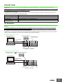
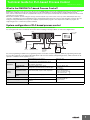
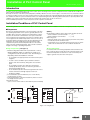
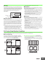
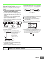
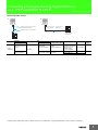
Technical Guide for PLC Basic CSM_PLC Basic_TG_E_1_1 Introduction This guide will describe the terminology needed for basic operation of the SYSMAC PLC (Programmable Controller), for clients new to our PLCs. This guide does not cover technical details regarding the setting of the FA System or PLC programming after purchase. I/O Refresh With the PLC (Programmable Controller), commands from user programs designed by the client are executed one by one and processed by reading and writing information in the internal PLC memory area (At OMRON, we call this the "I/O Memory"). At the same time, packages of data from sensors/switches that are directly connected to the basic I/O unit are exchanged with data in the PLC internal I/O Memory, at specific times. This process to totally exchange external data and internal I/O memory data is called "I/O Refresh Operation". It is important to know the timing by which the I/O Refresh will be executed when considering the operation of the FA System and User Programs designed by the client. In the case of the SYSMAC PLC, this I/O Refresh operation is performed immediately following the execution of all other commands. (See Figure below) PLC Inside PLC (CPU Unit) Common Processing (Self-Diagnosis) Execute Program PLC Processing Cycle Read/Write I/O Memory 0 0 0 0 0 0 0 0 0 0 1 1 0 1 1 0 0 1 1 1 1 0 1 0 1 0 0 0 0 0 0 0 0 1 0 0 0 0 0 1 Change (after all commands executed) Package 0 1 0 1 0 1 0 0 Exchange 0 1 1 0 1 0 1 0 1 1 0 0 1 0 1 0 1 0 1 1 1 0 1 1 1 0 0 0 1 1 0 1 Basic I/O Unit or built-in I/O I/O Refresh Refresh with external devices Peripheral Servicing External Data (Sensor, Switch, Actuator etc.) Cycle Time In terms of the PLC processing cycle, the cycle time is the time from the execution (commencement) of the I/O Refresh operation to the execution (processing) of the following I/O Refresh. The cycle time includes time for overhead processing (self-diagnosis), execution of user programs, I/O Refresh processing and the processing of peripheral services. • When the cycle time is long, the cycle for updating data from outside of the PLC and the I/O response time are also longer, making it impossible to implement changes that are input at a rate faster than the cycle time. • When the cycle time is short, I/O response time is also shortened, which allows high speed processing. • As the cycle time changes, the command execution cycle and I/O response times also change. In the case of the SYSMAC PLC, the cycle time can be requested in the following manner: Cycle Time = Overhead Processing Time + Total Command Execution Time + I/O Refresh Time + Peripheral Service Time The calculation methods for each execution time for the SYSMAC PLC are included in the product manual. 1 Interrupt Tasks Normally, user programs are executed in order along with the processing of the I/O Refresh etc., within the PLC processing cycle (See "I/O Refresh"). Interrupt Tasks however are executed in precedence to this processing cycle. In the event that certain interrupt conditions are met, the processing cycle will be suspended and the interrupt tasks will be executed first. (The SYSMAC PLC sometimes refers to the "Interrupt Tasks" as "Interrupt Programs", but here we shall use "Interrupt Tasks", the terminology used in the CS/CJ Series manuals) For example, in the case of the CS/CJ Series, Interrupt Tasks can include power Off interrupt, Scheduled Interrupts, I/O Interrupts, Periodic Interrupts based on the internal timer, and External Interrupts. Major Interrupt Tasks Power Break Interrupt Tasks Details Executed during a power break. Scheduled Interrupt Tasks Executed based on a specific schedule. I/O Interrupt Tasks Executed at the start-up of a connected Interrupt Input Unit. External Interrupt Tasks Executed when requests are received from the Special I/O unit, the CPU Bus Unit, and the INNER Board (only for CS Series). I/O Allocation In order for user programs to utilize I/O signals from the I/O Units mounted to the PLC, it is necessary to first assign an address within the PLC I/ O Memory. The assignment of I/O Memory to the input or output from these units within the PLC is known as I/O Allocation. The CPU Unit uses this I/O Allocation information in the operation of I/O Refresh with connected units. In the case of SYSMAC PLC, this I/O Allocation information is recorded in the PLC in the "Registered I/O Table". This "Registered I/O Table" can be created by either automatically registering online with programming tools utilizing information from the unit built-in to the PLC, or by using programming tools to design offline and then automatically registering by transmitting the I/O table to the PLC. (Some devices may not require the creation of a Registered I/O Table, and others may not support the offline design of I/O Tables.) ● Online Automatic Registration CX-Programmer or Programming Console Registered I/O Table Type and Location of Mounted Units "Create I/O Table" Operation CPU Unit I/O Units SYSMAC CJ/CS Series ● Offline Automatic Registration Type and locations of the Mounted Units Edit Registered I/O Table CX-Programmer "Create I/O Table" Operation CPU Unit I/O Units SYSMAC CJ/CS Series 2 CPU Unit Memory Area The PLC Unit utilizes a variety of different data including user programs, I/O Memory data and comments, CPU Unit and Special I/O units Parameters, and Registered I/O Table information etc. All of this data that is used by the PLC is stored in the memory area within the CPU unit. The SYSMAC PLC has the following types of Memory Areas, which is backed up by a battery. In the case of the SYSMAC CS/CJ Series, the content of the Memory Area is backed up using flash memory, which means that even if battery power fails, any user programs and parameter area data will not be lost. ● User Program Area This records user programs designed by the client. ● I/O Memory Area This Area is accessed by command operands. It records information such as the CIO, Internal I/O Area, holding area, auxiliary area, DM Area, EM Area, Timer Completion Flags/Present Value, Completion Flag/Present Value, Task Flags, Index Register, Data Register, Condition Flags, Clock Pulse, etc. The data in the I/O Memory Area locates in or is in areas in which the contents are cleared every time the power is turned back on, and areas in which prior information is retained. (In some areas you can select whether to clear or retain.) ● Parameter Area This contains all of the information regarding initial parameters used by the PLC. It records information such as the PLC System Parameters, Registered I/O Table, Routing Table, and PLC Setup for CPU Bus unit. 3 Technical Guide for PLC-based Process Control CSM_PLC Process_TG_E_1_1 What is the OMRON PLC-based Process Control? OMRON PLC-based Process Control system is based on the SYSMAC CS/CJ PLC Series. By adding PLC-based Process Control units to the basic system configuration, PLC process control functions can be simply added on to the basic functions already installed in the PLC. Thus, it can be used for devices that it is compatible with such process control system in which DCS was used before or devices in which several controllers were used combined. With the PLC Installation System, analog processing is carried out by the loop control section or the loop control unit/board (hereafter "loop controller"), and ladder processing is handled by the CPU. Communication between the two sections is made using bits of memory. Since the analog processing and ladder processing can be completely separated and the program is more simple than a ladder only program, the engineering process to construct the system is facilitated. System configuration of PLC-based process control The loop controller does not have an external analog I/O or an external contact I/O function. It is used together with such a unit that has the interface function including an analogue I/O unit, as shown in the diagram below. PLC PT or HMI Software Programming /Monitor PC 4 to 20 mA Sensor 4 to 20 mA Flow rate Sensor 4 to 20 mA 4 to 20 mA Capacitive Flow Rate Sensor Compensating 4 to 20 mA Leadwire Thermo Couple Process Also, when programming, in addition to the programming software for the CPU Unit (CX-Programmer, additional programming software (CXProcess) will be required to create Function block data. And in order to monitor and alter settings during operation, a HMI section will also be required, in combination with the application in use. Operation/Display Screen Creation Control Block/Sequence Creation CX-Process Tool CX-Programmer Application Section Batch management, brand management, remote surveillance (Web) Data gathering, data analysis Third Party Products etc Operation/Display Section Meter screen, graphics screen, trends, Warning history, operational history, operational guide CX-Process Monitor Plus NS Series etc. Loop Control Section Function Block (FBD), Sequence Table, Step ladder Loop Controller Loop Control Board/Unit or Process CPU/Loop CPU Loop Control Section Sequence Control Section Ladder, FB (Ladder/ST Language) CS/CJ Series CPU Program Creation Section HMI Section Control Section Signal I/O Section Analog I/O, Digital I/O, Pulse Input Signal Conversion (Signal Conditioner) Temperature, Current/Voltage, Isolator, Pulse, Distributor Field Device Sensor, Actuator ( ) Process/Analog I/O Unit Digital I/O Unit etc. 1 Installation of PLC Control Panel CSM_PLC Installation_TG_E_1_1 Introduction In order to ensure the reliability and security of the system, prior to the design of the system it is important to make certain that the conditions in which it will be installed is well understood. Basically, the stresses on the PLC system (temperature, humidity, vibrations, shocks, corrosive gases, overcurrent, noise etc.) need to be reduced as much as possible. However, the extent to which measures need to be taken in this regard will depend upon the likelihood of problems arising, the conditions in which the system is installed, and the cost of implementing measures. By taking advanced measures to prevent problems, the reliability of the system can be improved, and in the long-term the operation rate can also be increased. For the individual specifications of each unit, please see the respective user manuals. Installation/Conditions of PLC Control Panel The following describes the environmental conditions and measures to be taken for the installation of the PLC control panel (hereafter, "the panel") ■Temperature Based on the operating temperature of the element parts of the PLC, the operating temperature for the system is generally between 5°C and 40°C. At the same time, with both forced and natural cooling of the panel, the fact that it is miniaturized to save space means that from our experience the temperature of the panel is sometimes 10°C to 15°C higher than the ambient temperature of the room. As such, it is important that the following measures be taken depending on the installation site and the temperatures being generated to make certain that the panel's internal temperature does not exceed the range of the unit operating temperature, and to provide a sufficient margin for the range of operating temperature. (Notes) Environmental conditions and cooling system should be as follows. • Panel installed in room with low dust → 1 or 2 • Panel installed in room with dust → 3 or 4 When using a fan • Attach an air filter to the suction mouth to prevent the entry of dust • Periodically wash the air filter in water. • Temperature sensors should be attached near the PLC to emit an alarm in the event that the fan or air conditioner break down etc. ● Low Temperature ● High Temperature (see Figure 1) In cold areas where the morning temperature falls below 0°C at the time of start-up, attach a small space heater inside the panel to heat the internal temperature to about 5°C. In order for the PLC power supply to generate heat, don't turn off the power. 1Natural Cooling (Natural draft at the top and bottom of Panel) When installing the panel, it is optimal not to make use of cooling devices such as fans and coolers. The following are important points in the installation of the PLC. • Do not install in the upper part where the warm air in the panel stagnates • In order to ensure ventilation space, maintain a sufficient distance from other machinery, wiring ducts etc around the panel • Do not install in positions other than those specified (for example upside down), which can lead to the generation of abnormal heat within the PLC • Do not install directly above devices that generate heat such as heaters, transformers and high-capacity resistors etc. • Avoid direct sunlight 2Forced Ventilation (forced ventilation by use of a fan directly mounted at Top of Panel) 3Controlled Circulation (controlled circulation by means of a fan in the airtight enclosure panel) 4Full Room Cooling (Use a cooler to cool the entire room in which the panel is installed) Fan Fan PLC PLC PLC Cooler PLC PLC PLC Control Panel Air Filter 1Natural Cooling 2Controlled Ventilation 3Controlled Circulation 4Room Cooling System Figure 1. Cooling Board 1 ■Humidity be protected by rubber so that the shock is not felt. In order to maintain the insulating properties of the PLC, relative humidity should be kept within the range of 35% to 85%. In particular in the winter, when heaters are turned on and off, sudden changes in temperature may be experienced resulting in condensation which can lead to shorts or malfunctions. Where there is danger of such a change in temperature, power should be kept on during the night and condensation should be prevented through such measures as installing a small heater inside the panel to maintain low heat. (See Figure 2) Control Panel Absorbent Material PLC Turn on Power Heater Figure 2. Examples of Measures against Condensation ■Vibrations/Shocks The PLC is tested in accordance with the environmental (electricity and electrons) the sine wave vibration test method (JIS C0040/IEC68-2-6) and the shock test method (JIS C0041/IEC68-2-27), so that vibrations and shocks in the general specifications will not cause malfunctions. However, the system should not be installed in a place where it will be subject to regular vibrations or shocks, especially to the PLC and the panel. The following methods may be used to reduce the effect of vibrations and shocks. 1For vibrations and shocks that originate externally, the panel should be removed from the source. Alternatively, the PLC and the panel should be protected with the use of rubber. 2Isolate vibrations such as through the construction of the building, flooring etc. 3Regarding shocks experienced during magnetic contactor operation in the panel, the source of the shock or the PLC should ■Atmosphere When using the system in any of the following kind of places, connections may be loosened or elements and parts may experience corrosion, and an air purge should be implemented to avoid this. 1Places where dust, salt, particles, soot or organic solvents etc are common, and where the enclosure is sealed in such a way that the internal temperature does not increase very much. 2Where corrosive gases are common, an air purge (air purification) of the panel should be performed, to pressurize the panel and prevent the intrusion of air from outside. 3Places with flammable gases may be a cause of ignition. The system should not be used without a fire prevention mechanism in place. ■Work Space When installing the PLC and the panel, please consider their use, operability and maintenance, and pay particular attention to the following. 1Make sure that there is sufficient space to operate programs and to replace the unit. Further, for the sake of saftey and maintenance, installation should be as far as possible from high pressure or high power devices. 2Mount the PLC and I/O unit in a position in which the use of the debugging tool and the connection and operation of peripheral devices will be possible. 3The PLC and I/O unit generally has a maintenance light, and this should be easy for the operator to see, and in a position where it can easily be reached. 4For systems using the PLC as a control system, it is likely that there will be future additions and alterations to the system, so approx. 1020% extra space should be allowed for this. 5Where necessary, about 600 mm of space should be kept behind the panel for the purpose of performing maintenance. PLC Control Panel Electrical Conditions The power supply, grounding, and noise make up the main elements of the electrical conditions. In the installation and wiring of the device, great care must be taken to ensure that there is no danger to the human body, and that electrical signals are not obstructed (noise). ■PLC Installation Site For the sake of safety in maintenance and operation, installation should not be near high current (more than 600V) or high power devices. Where this cannot be avoided, installation should be as far away from such devices as possible. (See Figure 3) (Example of Recommended Equipment Arrangement) AC Unit AC Unit DC Unit DC Unit Panel with power line Communications Unit Control Panel CPU Control Panel 1The CPU and other adjoining units should be special or input units where noise generation is limited. 2The coils and contacts in electromagnetic contactors and relays in an external circuit are sources of noise. Locate them at least 100 mm away from the PLC. Power Unit PLC ● Arrangement of PLC and Each Unit (See Figure 4) (Example of Poor Equipment Arrangement) DC I/O Device AC I/O Device PLC Control Panel Control Panel Panel with power line Terminal Block Figure 4. Example of built-in type Figure 3. Examples of Equipment Arrangement in Panel with High-voltage Device 2 ■Power System Wiring (See Diagram 5) 1The power supply for the PLC and I/O devices should be separate, and a noise filter should be installed to the PLC power supply. 2Noise between the PLC and the ground can be greatly reduced by adding an isolating transformer. In such an event, do not ground the secondary coil of the transformer. 3Keep the wiring between the transformer and the PLC as short as possible, twist the wires well, and keep the wiring separate from high-voltage and power lines. 3Connect the shield to the ground terminal at the PLC, and leave it unconnected at the input device. 4Wire the lines so that common impedance does not occur. Such wiring will increase the number of wires, so use common return circuits. Use thick wires with sufficient allowance for the return circuits, and bundle them with lines of the same signal level. 5For long I/O lines, wire the input and output signal lines separately. 6Use twisted-pair wires for pilot lamps (and particularly lamps with filaments). 7Using a CR surge absorber or diode etc is effective in reducing noice sources from input devices or output load devices. Power Circuit ■External Wiring Power supply for general operations circuits PLC Input Circuit Power Supply PLC Output Circuit Power Supply PLC Power Supply Noise Filter Electric Socket (For peripheral devices) Diagram 5. Power Supply System Diagram ■Wiring External I/O Signal Lines 1To absorb reverse electromotive force when an inductive load is connected to an output signal, connect a surge protector near the inductive load in an AC circuit, and connect a diode near the inductive load in a DC circuit. (See Diagram 6 and 7) Inductive Load PLC DC Input Unit Diodes Connect a diode in a DC circuit Diagram 6. Input Signal Noise Countermeasures Inductive Load The wiring method can have a large impact on creating a system that is strong against noise and a system that can operate with a high degree of reliability. Wiring, and noise countermeasures in particular, are based on experience, and it is necessary to closely manage wiring based on experience and information in the manuals. ● Preventing Faulty Wiring 1By attaching marker bands to cables showing their direction, faulty wiring can be prevented, and wiring checks and maintenance can be facilitated. 2Use different colors during wiring. 3Place wires that transmit the same kind of signal into the same ducts, and separate them into groups. ● General Precautions 1Do not join wires between terminals. 2Support and fix the power line so that its end does not pull at the ends of multi-conductor cable. 3Use flexible wires for the movable places such as doors etc. Install them one part on the panel body and the other on the door so that they may not be damaged by the movement of a door. 4Connect crimp terminals to the end of the wire and use a torque driver for connection to the terminal, and screw in at an appropriate pressure. For terminal connection to an AC power unit, a roundtype crimp terminal should be used instead of a U shaped terminal, for safety purposes. 5The dust protection cover attached to the PLC unit should be kept in place until the wiring is completed to prevent dust from the wiring from entering. Further, as the internal temperature will increase greatly when the unit is in operation, the dust protection cover should be removed once wiring is completed to prevent loss in functionality. 6All wiring for the power circuit should be twisted. 7The primary or secondary noise filter should not be bundled, as this reduces its effectiveness. Inductive Load PLC Output Unit PLC Output Unit Affix surge protector for AC circuits Affix diodes for DC circuits Diagram 7. Output Signal Noise Countermeasures 2The output signal line should not be near or parallel with high current or power lines.When nearby, they should be separated by a duct, and an alternative wiring pipe should be established. In this event, the duct and wiring pipe must be grounded. (See Figure 8) I/O Cable I/O Cable Power Line Power Line Suspended Duct I/O Cable Floor Duct Type Power Line Piping Type Figure 8. I/O Cable Wiring 3 ● Wiring Route For the following combination, since signal types, properties, or levels of the signal differs, in principle different cables should be used or different routes should be used. Otherwise, the S/N (signal-to-noise ratio) resulting from electrical induction can fall. Also, by classifying and arranging the wiring, later maintenance or system changes can be simplified. 1Power lines and signal lines 2Input and output signals 3Analog and Digital Signals 4High level and low level signals 5Communication lines and Power line 6DC signals and AC signals 7High frequency aparatus (inverters etc.) and signal lines (communication) 4Do not install power cables and signal cables in parallel as they will adversely affect each other. 5When high-voltage devices are installed in the panel, due to noise, this should be separated as much as possible from high voltage and power lines when wiring. (See Figure 3) 6Install the PLC at least 200 mm from any high voltage or power lines, or make sure that the high current and power lines are contained within metal tubing, and ground to a resistance of 100 W. (See Figure 11) High-voltage power panel Metal tube Power Line Power Line 200 mm ● Wiring Method 1Isolate signal cables with different characteristics when routed in the same duct. 2Routing more than one power line in the same duct should be avoided as much as possible. Where this cannot be avoided, place a partition in the duct and ground it. (See Figure 9) Partition Signal Cable (A Group Signal Cable (B Group) Signal Cable (C Group) (a) Signal Cable Power Cable (b) Signal Cable Signal Cable Power Cable Power Cable (c) (d) Figure 9. Isolating Signal and Power Cables 3When using conduits in the course of wiring, the wires from one circuit should not place wires for a single circuit in separate conduits as the pipes heat up. (See Figure 10) Power Load Incorrect Use Power PLC PLC 200 mm Less than 100 W Figure 11. Example of Isolating PLC from Power Line ● Other Precautions 1I/O modules have plus and minus commons, so be careful of polarity when wiring. 2The outside of a fibre optic cable looks similar to a regular communication or power cable, but inside the cable there is the fibre and protective tension members and separators, so care should be taken when using them. Installation should be performed by the prescribed or standard methods, and care should be taken to not apply excessive shock, bend, twist, or excessive pulling. The following manuals have been prepared for wiring using fiber optic cables. 1SYSMAC C/CV Series Hard Plastic Clad Fiber Manual for laying Fibre Optics Cables (H-PCF) (Manual No. W156-E1) 2Controller Link Unit Fibre Optical Ring User Manual (Manual No. W370-E1) ■Grounding ● Purpose of Grounding There are two purposes for grounding. 1Protective grounding which prevents electrocution to people by maintaining an grounding against leakage, induction and occasional accidents. 2Grounding, including that to prevent external noise or noise which emenates from other devices or equipment, or noise that could disturb other devices or equipment, and that is necessary to protect device and system functions. These grounding issues may need to be resolved through experience and experimentation. It is important to take great care and consideration before performing the grounding. Load Correct Use Power Load Correct Use Figure 10. Parallel use of Electrical Wires (single phase) 4 ● Grounding Method and Precautions (1) Principles of One-point Grounding It would be best to consider that it is grounding that "determines electrical potential". Do not use common return circuits to return currents for grounding. Under normal conditions, do not send current through grounding lines (Do not use common return circuits to return currents for grounding.). (2) As much as possible use independent ground (keep grounding pole at least 10m away from other grounding poles). 1Use Ground to 100 W or less, and use independent ground which is separated from the grounding of other devices (See Figure 12 (a)) 2If using an independent ground is not possible, then use a common ground as shown in Figure 12 (b). Connect to the ground pole of the other device. 3Never connect to the same ground as a device that draws a large amount of power, such as a motor or inverter. Ground the devices separately to avoid mutually adverse influences. 4To prevent electrical shock, do not connect to ground poles (especially steel frames) to which multiple devices are connected. 5As much as possible keep the grounding pole close to the PLC, and keep the grounding line short. PLC PLC PLC Other Devices Other Devices Other Devices less than 100 W PLC Input Output Common (b) Common grounding.... Acceptable Common Figure 14. Shield Cable Grounding (4) PLC Protective Ground Terminal The PLC contains the following two ground terminals. : Protective ground terminal that is always connected to the PLC chassis for the prevention of electric shock. : Functional ground terminal: Connected to a neutral point in the noise filter to provide a ground when power supply noise causes malfunctioning. When properly grounded, the terminals will serve to reduce common mode noise from the power supply, but sometimes the grounding can result in picking up more noise, so care should be taken when using the terminals. AC Side (a) Exclusive Grounding.... Preferred PLC Side (c) Common grounding.... Incorrect Figure 12. Grounding Methods (3) Grounding Precautions 1If the same ground is used for both the signal lines and the enclosure, isolate the channel base (a grounded metal plate inside a control panel) with an insulating material. (See Figure 13) Exclusive Grounding 4When grounding the shield conductor in the event of shielded cable used in the wiring of input and output, connect the shield near the PLC to the enclosure ground terminal, as shown in Figure 14. For communication cables, please be sure to maintain shield processing in the communications unit manual. CS/CJ-series PLCs have an isolated (floating) mounting structure to make it more difficult to be affected by noise from the installation conditions such as a control panel. Diagram 15. PLC Grounding Terminal (5) Grounding for AC Power Supply Units When wiring to an AC Power Supply Unit. If one power supply phase of the equipment is grounded, always connect the grounded phase to the L2/N (or L1/N) terminal. L1 L2/N Isolator Common Base Figure 13. Example: Insulating and Grounding an Enclosure 2The panel which contains the PLC must be insulated from other electrical devices. This is to prevent the effect of the leakage of current from other electrical devices. 3When there is high frequency equipment nearby, please be sure that the panel which holds the PLC is grounded, in addition to the high frequency equipment. Bibliography 1Programable Controller Maintenance/Inspection Handbook May 2002 2SYSMAC CS Series User Manual Setup Edition NECA 5 Connecting a Computer Running Support Software (e.g., CX-Programmer) to a PLC CSM_Connecting_PLC_CG_E_8_2 Connecting Cables for CJ2 B A USB type A plug connector (male) D-sub connector D-sub connector (9-pin female) (9-pin male) Commercially available USB cable USB type B plug connector (male) USB port XW2Z-200S-CV/500S-CV(2 m/5 m) Computer Unit PC port PC/AT compatible Unit port USB A plug connector (female) USB B plug connector (female) Network Type (Serial Communications Mode) USB or Toolbus (USB port) CPU Unit D-sub, 9-pin (male) Built-in RS-232C port Host Link D-sub, 9-pin (female) RS-232C port D-sub connector (9-pin female) Model Cable length Commercially available USB cable * (A plug connector (male) - B plug connector (male)) 5 m maximum XW2Z-500S-CV 5m XW2Z-200S-CV 2m Connection Types A B * A driver must first be installed to make a USB connection. Company names and product names in this document are the trademarks or registered trademarks of their respective companies. 1 Connecting a Computer Running Support Software (e.g., CX-Programmer) to a PLC Connecting Cables for CS1/CJ1 B A CS/CJ-series peripheral connector D-sub connector (9-pin female) Peripheral port D-sub connector (9-pin female) RS-232C port D-sub connector D-sub connector (9-pin female) CS/CJ-series (9-pin male) peripheral connector CS/CJ Series CS/CJ Series XW2Z-200S-CV/500S-CV (2 m/5 m) or XW2Z-200S-V/500S-V (2 m/5 m) CS1W-CN118 (10 cm) CS1W-CN226/626 (2 m/6 m) Peripheral port D C D-sub connector (9-pin female) CS/CJ-series peripheral connector C-series peripheral connector D-sub connector (9-pin male) D-sub connector (9-pin female) CS/CJ Series CS/CJ Series RS-232C port D-sub connector (9-pin female) CQM1-CIF02 (3.3 m) Peripheral port CS1W-CN114 (5 cm) Computer Unit PC port Unit port XW2Z-200S-CV/500S-CV (2 m/5 m) or XW2Z-200S-V/500S-V (2 m/5 m) Network Type (Serial Communications Mode) Peripheral bus or Host Link Built-in peripheral port PC/AT D-sub, 9-pin (male) compatible Host Link CPU Model CS1W-CN226 2m CS1W-CN626 6m CS1W-CN118 +XW2Z-200S-CV 0.1 m+2 m CS1W-CN118 +XW2Z-500S-CV 0.1m+5 m CS1W-CN118 +XW2Z-200S-V 0.1 m+2 m CS1W-CN118 +XW2Z-500S-V 0.1 m+5 m Host Link with a baud CS1W-CN114 rate of 19.2 kbps or less +CQM1-CIF02 Peripheral bus or Host Built-in RS-232C port Link D-sub, 9-pin (female) Host Link Cable length Connection Types A B 0.05 m+3.3 m XW2Z-200S-CV 2m XW2Z-500S-CV 5m XW2Z-200S-V 2m XW2Z-500S-V 5m C D Reference: USB-Serial Conversion Cable (CS1W-CIF31) A USB type A plug connector (male) CS1W-CIF31 (50 cm) D-sub connector (9-pin male) CS/CJ-series peripheral connector D-sub connector (9-pin female) Peripheral port CS/CJ Series * CS1W-CN226/626 (2 m/6 m) Computer Connecting Cable PC port PC/AT USB A plug connector compatible (female) Cable port − Network Type (Serial Communications Mode) RS-232C Depends on the Unit's D-sub, 9-pin (female) spcifications. Model CS1W-CIF31 *2 Cable length 0.5 m Connection Types A *1. Applicable models: CS/CJ Series, C Series (C200HS, C200HE/G/X, C200H, C1000H, C2000H, CQM1, CPM1, CPM1A, CPM2A, CQM1H, and CPM2C), CVM1/CV Series, NS Series, NT Series, SRM1, and ZEN. *2. A separate cable is required to connect to the PLC. 2 Connecting a Computer Running Support Software (e.g., CX-Programmer) to a PLC Connecting Cables for CP1H/CP1L/CP1E A B RS-232C port D-sub connector (9-pin female) RS-232C Option Board CP1W-CIF01 D-sub connector (9-pin female) USB type A plug connector (male) CP1H/CP1L/CP1E-N/NA Commercially available USB cable USB type B plug connector (male) USB port XW2Z-200S-CV/500S-CV (2 m/5 m) or XW2Z-200S-V/500S-V (2 m/5 m) CP1H/CP1L/CP1E Computer Unit PC port USB A plug connector (female) PC/AT compatible Network Type (Serial Communications Mode) Unit port USB B plug connector (female) CPU USB RS-232C port (D-sub Peripheral bus or Host Link 9-pin female) on Option Board * D-sub, 9-pin (female) Host Link D-sub, 9-pin (male) Model Cable length Commercially available USB cable (A plug connector (male) - B plug connector (male)) 5 m maximum XW2Z-200S-CV 2m XW2Z-500S-CV 5m XW2Z-200S-V 2m XW2Z-500S-V 5m Connection Types A B * An Option Board cannot be used with a CP1L CPU Unit with 10 Points and CP1E-E. Also, the CP1E-N and CP1E-NA have a built-in RS-232C port. Connecting Cables for C200HS/HX/HG/HE A C-series peripheral connector D-sub connector (9-pin female) Peripheral port C200HX/HG/HE CQM1-CIF02 (3.3 m) B C D-sub connector (9-pin male) D-sub connector (9-pin female) D-sub connector (9-pin female) C200HX/HG/HE D-sub connector (25-pin male) Host Link Unit C200H-LK201-V1 C200HX/HG/HE RS-232C port D-sub connector (25-pin male) RS-232C port D-sub connector (9-pin female) XW2Z-200P-V/500P-V (2 m/5 m) XW2Z-200S-CV/500S-CV (2 or 5 m) or XW2Z-200S-V/500S-V (2 or 5 m) Computer Unit PC port Unit port Built-in peripheral port CPU PC/AT D-sub, 9-pin (male) compatible Host Link Unit C200H-LK201-V1 Built-in RS-232C port D-sub, 9-pin (female) *2 Built-in RS-232C port D-sub, 25-pin (female) Network Type (Serial Communications Mode) Peripheral bus *1 or Host Link Host Link Model Cable length CQM1-CIF02 3.3 m XW2Z-200S-CV 2m XW2Z-500S-CV 5m XW2Z-200S-V 2m XW2Z-500S-V 5m XW2Z-200P-V *3 2m XW2Z-500P-V *3 5m Connection Types A B C *1. These Cables cannot be used for Programming Devices, such as the CX-Programmer, for the C200H-LK201-V1 Host Link Unit on a C200HX/ HG/HE-Z PLC. *2. Only C200HS-CPU21/23/31/33 is equipped with a built-in RS-232C port D-sub, 9-pin (female). *3. The XW2Z-200S-CV and XW2Z-500S-CV cannot be used. 3 Connecting a Computer Running Support Software (e.g., CX-Programmer) to a PLC Connecting Cables for CQM1H A B D-sub connector (9-pin female) CS/CJ-series peripheral connector Peripheral port D-sub connector (9-pin female) C-series peripheral connector CS/CJ-series peripheral connector CQM1H CQM1H CS1W-CN226/626 (2 m/6 m) CQM1-CIF02 (3.3 m) Peripheral port CS1W-CN114 (5 cm) C D D-sub connector (9-pin male) D-sub connector (9-pin female) RS-232C port D-sub connector (9-pin female) CS/CJ-series peripheral connector D-sub connector (9-pin female) CQM1H XW2Z-200S-CV/500S-CV (2 m/5 m) or XW2Z-200S-V/500S-V (2 m/5 m) Peripheral port XW2Z-200S-CV/500S-CV (2 or 5 m) or XW2Z-200S-V/500S-V (2 or 5 m) Unit PC port Network Type (Serial Communications Mode) Unit port Built-in peripheral port PC/AT D-sub, 9-pin (male) compatible RS-232C port D-sub connector (9-pin female) CQM1H CS1W-CN118 (10 cm) Computer D-sub connector (9-pin male) Peripheral bus or Host Link CPU * Built-in RS-232C port Host Link D-sub, 9-pin (female) Model Cable length CS1W-CN226 2m CS1W-CN626 6m CS1W-CN114 +CQM1-CIF02 0.05 m+3.3 m CS1W-CN118 +XW2Z-200S-CV 0.1 m+2 m CS1W-CN118 +XW2Z-500S-CV 0.1 m+5 m CS1W-CN118 +XW2Z-200S-V 0.1 m+2 m CS1W-CN118 +XW2Z-500S-V 0.1 m+5 m XW2Z-200S-CV 2m Connection Types A B C XW2Z-500S-CV 5m XW2Z-200S-V 2m XW2Z-500S-V 5m D * Discontinuation models in March 2012. Connecting Cables for CQM1 A B C-series peripheral connector Peripheral port D-sub connector (9-pin female) CQM1 D-sub connector (9-pin female) D-sub connector RS-232C port (9-pin male) (9-pin female) CQM1 CQM1-CIF02 (3.3 m) XW2Z-200S-CV/500S-CV (2 m/5 m) or XW2Z-200S-V/500S-V (2 m/5 m) Computer Unit PC port Unit port Built-in peripheral port PC/AT D-sub, 9-pin (male) compatible CPU * Network Type (Serial Communications Mode) Peripheral bus or Host Link Built-in RS-232C port D-sub, 9-pin (female) Host Link (CPU42/43/44/63/64/ 65/85 only) Model Cable length CQM1-CIF02 3.3 m XW2Z-200S-CV 2m XW2Z-500S-CV 5m XW2Z-200S-V 2m XW2Z-500S-V 5m Connection Types A B * Discontinuation models in March 2001. 4 Connecting a Computer Running Support Software (e.g., CX-Programmer) to a PLC Connecting Cables for CPM1, CPM1A and CPM2A B A C-series peripheral connector Peripheral port D-sub connector (9-pin female) CPM1A-V1 D-sub connector (9-pin female) D-sub connector (9-pin male) CPM1-CIF01 Peripheral port CQM1-CIF02 (3.3 m) XW2Z-200S-CV/500S-CV (2m/5m) or XW2Z-200S-V/500S-V (2m/5m) Computer Unit PC port Unit port Network Type (Serial Communications Mode) Peripheral bus * or Host Link PC/AT D-sub, 9-pin (male) compatible Built-in peripheral port CPU Unit Host Link CPM1A-V1 Model Cable length CQM1-CIF02 3.3 m CPM1-CIF01 +XW2Z-200S-CV 2m CPM1-CIF01 +XW2Z-500S-CV 5m CPM1-CIF01 +XW2Z-200S-V 2m CPM1-CIF01 +XW2Z-500S-V 5m Connection Types A B * CPM2A CPU Units that have a 9 as the fourth digit of the lot number (4 or 5 digits) do not support Toolbus connections. They do support Host Link connections. Note: Including models whose production are discontinued. Connecting Cables for SRM1 A B C-series peripheral connector Peripheral port D-sub connector (9-pin female) C D-sub connector (9-pin male) D-sub connector (9-pin male) D-sub connector CPM1-CIF01 (9-pin female) D-sub connector (9-pin female) RS-232C port D-sub connector (9-pin female) CQM1-CIF02 3.3 m SRM1 XW2Z-200S-CV/500S-CV (2m/5m) or XW2Z-200S-V/500S-V (2m/5m) Peripheral port SRM1 XW2Z-200S-CV/500S-CV (2m/5m) or XW2Z-200S-V/500S-V (2m/5m) SRM1 Computer Unit PC port Unit port Network Type (Serial Communications Mode) Peripheral bus or Host Link Built-in peripheral port PC/AT D-sub, 9-pin (male) compatible CPU Unit Host Link Built-in RS-232C port D-sub, 9-pin (female) (SRM1-C01 only) Model Cable length CQM1-CIF02 3.3 m CPM1-CIF01 +XW2Z-200S-CV 2m CPM1-CIF01 +XW2Z-500S-CV 5m CPM1-CIF01 +XW2Z-200S-V 2m CPM1-CIF01 +XW2Z-500S-V 5m XW2Z-200S-CV 2m Connection Types A B XW2Z-500S-CV 5m XW2Z-200S-V 2m XW2Z-500S-V 5m C Note: Including models whose production are discontinued. 5 Connecting a Computer Running Support Software (e.g., CX-Programmer) to a PLC Connecting Cables for CPM2C A B CS/CJ-series peripheral connector D-sub connector (9-pin female) Peripheral port CS/CJ-series peripheral connector C-series peripheral connector D-sub connector (9-pin female) Peripheral port CPM2C CPM2C CS1W-CN226/626 (2 m/6 m) CQM1-CIF02 (3.3 m) CS1W-CN114 (5 cm) C D C-series peripheral connector D-sub connector (9-pin female) C-series peripheral connector D-sub connector (9-pin female) CPM2C-CIF01-V1 CS/CJ-series peripheral connector Peripheral port Peripheral port CPM2C CQM1-CIF02 (3.3 m) CPM2C CQM1-CIF02 (3.3 m) CS1W-CN114 (5 cm) CS/CJ-series peripheral connector XW2Z-200T/500T CPM2C-CN111 F E D-sub connector (9-pin female) D-sub connector (9-pin male) RS-232C port D-sub connector (9-pin female) RS-232C port D-sub connector D-sub (9-pin female) (9-pin male) CS/CJ-series peripheral connector CS/CJ-series peripheral connector Peripheral port D-sub connector (9-pin female) CPM2C Peripheral port XW2Z-200S-CV/500S-CV (2 m/5 m) or XW2Z-200S-V/500S-V (2 m/5 m) XW2Z-200S-CV/500S-CV (2 m/5 m) or XW2Z-200S-V/500S-V (2 m/5 m) CS1W-CN118 (10 cm) CPM2C CPM2C-CN111 G H RS-232C port D-sub connector (9-pin female) XW2Z-200T/500T CPM2C-CIF01-V1 CS/CJ-series peripheral connector Peripheral port D-sub connector (9-pin female) XW2Z-200S-CV/500S-CV (2 m/5 m) or XW2Z-200S-V/500S-V (2 m/5 m) D-sub connector (9-pin male) D-sub connector (9-pin female) CPM2C-CIF01-V1 Peripheral port CPM2C XW2Z-200S-CV/500S-CV (2 m/5 m) or XW2Z-200S-V/500S-V (2 m/5 m) D-sub connector (9-pin male) CPM2C CS1W-CN118 (10 cm) CS/CJ-series peripheral connector I D-sub connector (9-pin male) CPM2C-CIF11/CIF21 D-sub connector (9-pin female) Peripheral port CPM2C XW2Z-200S-V/500S-V (2 m/5 m) CS/CJ-series peripheral connector 6 Connecting a Computer Running Support Software (e.g., CX-Programmer) to a PLC Computer Unit PC port Unit port Communications port (as a peripheral port) PC/AT compatible D-sub, 9-pin (male) Network Type (Serial Communications Mode) Peripheral bus *1 or Host Link CPU Communications port (as an RS-232C port) Host Link Model Cable length Connection Types CS1W-CN226 *2 2m CS1W-CN626 *2 6m CS1W-CN114 +CQM1-CIF02 0.05 m+3.3 m B CPM2C-CIF01-V1 +CS1W-CN114 +CQM1-CIF02 Adapter+ 0.05 m + 3.3 m C CPM2C-CN111 (Peripheral port) +CQM1-CIF02 0.1 m+3.3 m D CS1W-CN118 +XW2Z-200S-CV 0.1 m+2 m CS1W-CN118 +XW2Z-500S-CV 0.1 m+5 m CS1W-CN118 +XW2Z-200S-V 0.1 m+2 m CS1W-CN118 +XW2Z-500S-V 0.1 m+5 m CPM2C-CN111 (RS-232C port) +XW2Z-200S-CV 0.1m+2m CPM2C-CN111 (RS-232C port) +XW2Z-500S-CV 0.1 m+5 m CPM2C-CN111 (RS-232C port) +XW2Z-200S-V 0.1 m+2 m CPM2C-CN111 (RS-232C port) +XW2Z-500S-V 0.1 m+5 m CPM2C-CIF01-V1 +XW2Z-200S-CV Adapter+2 m CPM2C-CIF01-V1 +XW2Z-500S-CV Adapter+5 m CPM2C-CIF01-V1 +XW2Z-200S-V Adapter+2 m CPM2C-CIF01-V1 +XW2Z-500S-V Adapter+5 m CPM2C-CIF01-V1 +CS1W-CN118 +XW2Z-200S-CV Adapter 0.1 m+2 m CPM2C-CIF01-V1 +CS1W-CN118 +XW2Z-500S-CV Adapter 0.1 m+5 m CPM2C-CIF01-V1 +CS1W-CN118 +XW2Z-200S-V Adapter+ 0.1 m+2 m CPM2C-CIF01-V1 +CS1W-CN118 +XW2Z-500S-V Adapter+ 0.1 m+5 m CPM2C-CIF11 +XW2Z-200S-V Adapter+2 m CPM2C-CIF11 +XW2Z-500S-V Adapter+5 m CPM2C-CIF21 +XW2Z-200S-V Adapter+2 m CPM2C-CIF21 +XW2Z-500S-V Adapter+5 m A E F G H I *1. CPM2C CPU Units that have a 9 as the fourth digit of the lot number (4 or 5 digits) and that were manufactured in 1999 do not support Toolbus connections. They do support Host Link connections. *2. Only Host Link (SYSMAC WAY) connections are possible. Toolbus cannot be used. Note: Refer to the CPM2C Operation Manual (Cat. No. W340) for details. 7 Connecting a Computer Running Support Software (e.g., CX-Programmer) to a PLC Connecting Cables for C1000H, C2000H, C200H B A Peripheral port C-series peripheral connector D-sub connector (25-pin male) C1000H, C2000H, C200H Series D-sub connector (9-pin female) C1000H, C2000H, C200H Series D-sub connector (9-pin female) CQM1-CIF02 (3.3 m) C200H-IP007 Computer XW2Z-200P-V/500P-V (2 m/5 m) Unit PC port Network Type (Serial Communications Mode) Unit port Built-in peripheral port CPU Unit PC/AT D-sub, 9-pin (male) compatible Host Link Unit C1000H, C2000H: C500-LK203 C500-LK201-V1 (3G2A5-LK201-V1) C120-LK201-V1 (3G2A6-LK201-EV1) C200H: C200H-LK201-V1 C120-LK201-V1 (3G2A6-LK201-EV1) Model Cable length C200H-IP007 +CQM1-CIF02 * 3.3 m XW2Z-200P-V 2m Connection Types A Built-in RS-232C port Host Link D-sub, 25-pin (female) B XW2Z-500P-V 5m * Connection cannot be made from the CQM1-CIF02 directly to a computer for the C200H Handheld Programming Console connecting cable. Use the C200H-IP007. Connecting Cables for CVM1/CV A B CV-series D-sub connector (9-pin female) peripheral Commercially available connector 25-pin/9-pin straight conversion cable D-sub connector (25-pin female) D-sub connector (25-pin male) D-sub connector (9-pin male) D-sub connector (9-pin female) Peripheral port CVM1/CV Series CVM1/CV Series RS-232C port D-sub connector (9-pin female) XW2Z-200S-V/500S-V (2 m/5 m) CV500-CIF01 C D Host Link Unit CV500-LK201 *1 D-sub connector (For full duplex (25-pin male) communications on port 1) D-sub connector (9-pin female) Host Link Unit CV500-LK201 *1 D-sub connector (For full duplex communications on port 2) D-sub connector (9-pin male) (9-pin female) CVM1/CV Series CVM1/CV Series RS-232C port D-sub connector (25-pin female) RS-232C port D-sub connector (9-pin female) XW2Z-200P-V/500P-V (2 m/5 m) XW2Z-200S-V/500S-V (2 m/5 m) Computer Unit PC port Unit port Network Type (Serial Communications Mode) Built-in peripheral port CPU Unit *1 PC/AT D-sub, 9-pin (male) compatible Built-in RS-232C port D-sub, 9-pin (female) Host Link Unit CV500-LK201 *1 (for full duplex communication on port 1) Built-in RS-232C port Host Link D-sub, 25-pin (female) Host Link Unit CV500-LK201 *1 (for full duplex communication on port 2) Built-in RS-232C port D-sub, 9-pin (female) Model Cable length CV500-CIF01 *2 6m XW2Z-200S-V *3 2m XW2Z-500S-V *3 5m XW2Z-200P-V *3 2m XW2Z-500P-V *3 5m XW2Z-200S-V *3 2m XW2Z-500S-V *3 5m Connection Types A B C D *1. Discontinuation models in March 2012. *2. A commercially available 25-pin/9-pin straight conversion cable is separately required. *3. The XW2Z-200S-CV and XW2Z-500S-CV cannot be used. 8 Connecting a Computer Running Support Software (e.g., CX-Programmer) to a PLC Connecting Cables for C500 A B Peripheral port C-series peripheral connector D-sub connector (25-pin male) C500 Series D-sub connector (9-pin female) CQM1-CIF02 (3.3 m) C200H-IP007 Computer XW2Z-200P-V/500P-V (2 m/5 m) Unit PC port PC/AT D-sub, 9-pin (male) compatible C500 Series D-sub connector (9-pin female) Network Type (Serial Communications Mode) Unit port CPU Unit *1 Built-in peripheral port Host Link Unit *2 C500-LK203 C500-LK201-V1 (3G2A5-LK201-EV1) C120-LK201-V1 (3G2A6-LK201-EV1) Built-in RS-232C port Host Link D-sub, 25-pin (female) Model Cable length C200H-IP007 +CQM1-CIF02 3.3 m XW2Z-200P-V 2m XW2Z-500P-V 5m Connection Types A B *1. Production of the CPU Units was discontinued in March 2004. *2. Production of the C500-LK203, C500-LK201-V1 (3G2A5-LK201-EV1), and C120-LK201-V1 (3G2A6-LK201-EV1) was discontinued in March 2006. (There is no recommended substitute product.) Connecting Cables for C120 B A Peripheral port C-series peripheral connector D-sub connector (25-pin male) D-sub connector (9-pin female) CQM1-CIF02 (3.3 m) D-sub connector (9-pin female) C200H-IP007 Computer C120 Series XW2Z-200P-V/500P-V (2 m/5 m) Unit PC port PC/AT D-sub, 9-pin (male) compatible C20-LK201-V1 Host Link Unit C120 Series Unit port Network Type (Serial Communications Mode) Model Cable length CPU Unit *1 Built-in peripheral port C200H-IP007 +CQM1-CIF02 3.3 m Host Link Unit *2 C120-LK201-V1 (3G2A6-LK201-EV1) Built-in RS-232C port Host Link D-sub, 25-pin (female) XW2Z-200P-V 2m XW2Z-500P-V 5m Connection Types A B *1. Production of the CPU Units was discontinued in March 2003. *2. Production of the C120-LK201-V1 was discontinued in March 2006. (There is no recommended substitute product.) 9 Connecting a Computer Running Support Software (e.g., CX-Programmer) to a PLC Connecting Cables for C20P/C28P/C40P/C60P*1, C20K/C28K/C40K/C60K*2 A Host Link Unit C20-LK201-V1 D-sub connector (9-pin female) C20P, C28P, C40P, C60P, C20K, C28K, C40K, C60K Series D-sub connector (25-pin male) XW2Z-200P-V/500P-V (2 m/5 m) Computer Unit PC port PC/AT D-sub, 9-pin (male) compatible Network Type (Serial Communications Mode) Unit port Host Link Unit *3 *4 C20-LK201-V1 (3G2C7-LK201-EV1) Built-in RS-232C port D-sub, 25-pin Host Link (female) Model Cable length XW2Z-200P-V 2m XW2Z-500P-V 5m Connection Types A *1. Production of the C20P, C28P, C40P, and C60P CPU Units was discontinued in March 2002. *2. Production of the C20K, C28K, C40K, and C60K CPU Units was discontinued in March 2002. *3. For connection to CP PLCs, a Host Link Unit is also required in addition to a Connecting Cable. *4. Production of the C20-LK201-V1 (3G2C7-LK201-EV1) was discontinued in March 2006. (There is no recommended substitute product.) Connecting Cables for NSJ B A D-sub connector (9-pin male) USB type A plug connector (male) D-sub connector (9-pin female) Commercially available USB cable USB type B plug connector (male) Unit PC port Unit port USB A plug connector (male) PC/AT compatible USB B plug connector (female) CPU D-sub, 9-pin (male) SYSMAC One NSJ-series Controller XW2Z-200S-CV/500S-CV (2 m/5 m) or XW2Z-200S-V/500S-V (2 m/5 m) SYSMAC One NSJ-series Controller Computer RS-232C port D-sub connector (9-pin female) Network Type (Serial Communications Mode) USB Peripheral bus or Host Built-in RS-232C port Link D-sub, 9-pin (female) Host Link Model Cable length Commercially available USB cable (A plug connector (male) - B plug connector (male)) 5 m maximum XW2Z-200S-CV 2m XW2Z-500S-CV 5m XW2Z-200S-V 2m XW2Z-500S-V 5m Connection Types A B 10