1
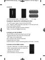
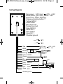
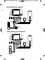
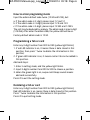
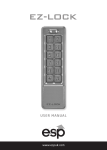
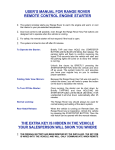
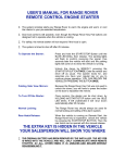
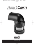
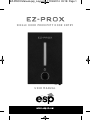
EZ-PROX Manual.qxp_Layout 1 17/04/2014 09:18 Page 1
EZ-PROX
S I N G L E D O O R P R OX I M I T Y D O O R E N T R Y
USER MANUAL
EZ-PROX Manual.qxp_Layout 1 17/04/2014 09:18 Page 2
Contents
EZ-PROX and back plate
EZ-PROX remote
10 x Tags
Equipment required for controlling one door:
12 volt DC power supply 2 amp minimum (EV-BPS)
Lock - Magnetic (EVML-250)/Yale type keep 12 volt lock (enter D)
Push to exit button (EVEXIT)
Green break glass emergency release (EVEBG)*
*Note:- for use with Magnetic lock only
Functions of the EZ-PROX
The EZ-PROX can control one door by use of tags.
Programmable door open time 00 to 99 seconds.
1000 Tags can be programmed.
Door closed function (contact required).
Programmable rear tamper.
Internal buzzer for tamper monitoring (auto cut off after 1 minute).
Functions of EZ-PROX remote
• Two No.7 LR03 AAA 1.5V alkaline batteries
• Enter corresponded number to replace the
relative ID/IC card and fob
• Working current: 0.5mA
• Sensor distance: all around: 20cm
EZ-PROX Manual.qxp_Layout 1 17/04/2014 09:18 Page 3
Installation
Before installation, position the location where the controller unit
is mounted. Please operate it according to the following steps:
1. Open the controller by loosening and removing the back case
screw at the bottom with the spline tool.
2. Use the provided drilling template to accurately locate and drill
the required holes. The four drilling holes are marked "B".
3. Use the screws provided to mount the back case on the wall.
Be sure to draw the wiring through the large centre hole in
back case, and keep level.
4. Connected accurately the system wiring following the label
enclosed on the rear.
5. Put the unit back and screw it on by using the spline tool.
Hole
Screw anchor
Back cover
Screw
Indicator
Screw
Hole
114mm
).
Bell button
Screw
Screw
Screw
Screw
20
75mm
Remote control
IR sensor
EZ-PROX Manual.qxp_Layout 1 17/04/2014 09:18 Page 4
Wiring Diagram
Red-power
DC input
+12V - +24V
Black-power AC input ~ 12V - 24V
Brown-door status detecting
Orange-unlocking button 1
Yellow-DATA 1
Green-GND
Blue-Door bell
Purple-Door bell
Gray-DATA 0
White-NO 1
Pink-COM 1
Aqua-NC 1
Shielded ground
Red
Black
DC input
+12V - +24V
AC input ~ 12V - 24V
Brown
Orange
Yellow DATA 1
Green
Blue
Purple
Gray DATA 0
White NO 1
Pink COM 1
Aqua NC 1
Shielded ground
DC
05D390K
EZ-PROX Manual.qxp_Layout 1 17/04/2014 09:18 Page 5
Wiring Diagram for Maglock
EV-BPS
4V
L
N
240vAC
INPUT
Timer
N.C
E.lock DC out Push button
+ + - GND P.B
Exit Button
PINK
Capacitor
0.47uF
100v
WHITE
RED
Maglock
BLACK
0-20
secs
COM
Emergency
door release
N.C
Wiring Diagram for Yale Release
EV-BPS
240vAC
INPUT
L
N
4V
PINK
Yale Release
RED
K
WHITE
N.O
0-20
secs
BLACK
Timer
E.lock DC out Push button
+ + - GND P.B
Exit Button
EZ-PROX Manual.qxp_Layout 1 17/04/2014 09:18 Page 6
How to enter programing mode
Input the admin default code twice (1234 and1234), but:
a. If the admin code is 2-digit, please input 12 and 12
b. If the admin code is 3-digit, please input 123 and 123
c. If the admin code is 5-digit, please input 12345 and 12345
The rest may be deduced by analogy. The admin code is max 6-digit
(123456). After enter the admin code, the yellow LED will be on.
Factory default admin code is 1234.
Programming a fob or card
Enter any 3-digit number from 000 to 999 (yellow light blinks):
1. If red LED indicator is on, it means there is data stored in this
position, then press * twice to delete the information in this
position;
2. If green LED indicator is on, it means card or fob can be added in
this position.
Add card steps:
1. Enter in setting mode, and the yellow light blinks.
2. Input 3-digits number from 000 to 999 to choose a position.
3. When the green light is on, swipe card. Bleep sounds means
add card successfully.
Press # to exit the setting mode.
Deleteing a fob or card
Enter any 3-digit number from 000 to 999 (yellow light blinks):
Red LED indicator is on, means there is data stored in this position.
Press * twice to delete the information in this position.
Press # to quit setting mode.
EZ-PROX Manual.qxp_Layout 1 17/04/2014 09:18 Page 7
Programing a group of fobs or cards
In the setting mode:
t
Press * 9 (yellow light blinks), then press 0 1 (Bleep sounds). Input
3-digit number(any one from 000 to 999. It indicates the card
adding starts from this number. For example, enter 050 indicates
the card is added from NO.50). Then add another 3-digit number
indicates the quantity of cards to be added (for example, if 50
cards need to be added, enter 050. If 150 cards are added, enter
150). After Bleep is heard, enter 8-digit card number of the first
card or fob added or swipe the card or fob. Bleep sound indicates
the cards numbers added are successful.
Press # to exit the setting mode.
Set door open time
In the setting mode:
n
Press * 1 (yellow light blinks). Then enter any 2-digit number from
00 to 99. Bleep sounds and yellow light stops blinking indicate
the setting is successful.
00-99 means the delay time. For example, 05 means the door
open time is 5seconds (delayed). If time is set as 00, it means:
swipe a card once to open the door, and swipe the card once
again to close the door immediately.
Press # to exit the setting mode.
The pickproof alarm
.
The built-in buzzer will sound a continuous Bleep Bleep. If the
photoresistor sensor is directly exposed to the light. The buzzer
will be off automatically in 60 seconds, or when the light is no
longer detected, or by entering the admin code.
EZ-PROX Manual.qxp_Layout 1 17/04/2014 09:18 Page 8
Changing the Programming code
In the setting mode:
Press * 3 (yellow light blinks). Then input new administrator code
twice (The length of the new admin code must be the same as
the old one). Bleep - sound means it modifies successfully.
Press # to exit the setting mode.
Turn on/off the pickproof alarm
In the setting mode:
Press * 6 (yellow light blinks), then press 0 1 (Bleep - sound, and
yellow light stops blinks). Pickproof alarm is turned off.
Press * 6 (yellow light blinks), then press 0 2 (Bleep - sound, and
yellow light stops blinks). Pickproof alarm is turned on.
Press # to exit the setting mode.
Turn on /off fob or card number detection
In the setting mode:
Press * 2 (yellow light blinks), then press 0 1 (Bleep sound, and
yellow light stops blink) to turn on the card number detection.
Press * 2 (yellow light blinks), then press 0 2 (Bleep sound, and
yellow light stops blink) to turn off the card number detection.
Press # to exit the setting mode.
EZ-PROX Manual.qxp_Layout 1 17/04/2014 09:18 Page 9
Programming a Master Fob or Card
In the setting mode:
Press * 7
1. Green light blinks indicates there is no master card or fob stored.
Then swipe a card or fob. Bleep sounds indicates this card is
added as a master card.
2. Green light turns on indicates there is master card. Press *
twice to delete this master card or fob. Then green light blinks.
New master card or fob can be added. Swipe a card or fob, and
Bleep sounds. Green light stops blinks indicates new master
card or fob is added successfully.
Press # to exit the setting mode.
Use the master card or fob to enter the setting mode
Swipe the master card or fob. Yellow light is on with Bleep sound
means it enters the setting mode. Swipe the master card or fob
again. The Bleep Bleep Bleep sound means it exits the setting
mode. The blue light is on.
EZ-PROX Manual.qxp_Layout 1 17/04/2014 09:18 Page 10
Delete all user fobs and cards and restore to
factory default
In the setting mode:
Press * 8 (yellow light blinks), then press 8 twice (Bleep Bleep ...
Sounds, yellow light stops blinking). It indicates all user cards or
fobs have been deleted successfully. All the card or fob settings
are invalid.
Press * 8 (yellow light blinks), then press 9 twice (yellow light is
on, and Bleep sounds). Restore to factory default setting
successfully. All the settings are in default status.
Press # to exit the setting mode.
If enter wrong information, Bleep Bleep will be heard. The
setting mode will exit automatically if no actions in 30 seconds
accompanied with Bleep Bleep sound. If it is not in the setting
mode and the action of pressing numbers is uncompleted, it will
exit automatically in 5 seconds accompanied with Bleep Bleep
sound.
In case forget the admin code, power on first, then press #
(within 3 seconds). A sound Bleep indicates restore to factory
defaults successfully.
Digit length is 2 means default admin code is 12,
Digit length is 3 means default admin code is 123,
Digit length is 4 means default admin code is 1234,
Digit length is 5 means default admin code is 12345,
Digit length is 6 means default admin code is 123456 (Max. is 6).
The access control will be locked for 60 seconds if input wrong
codes continuously (or swipe the invalid card) for 5 times (both
the keypad operating and the card swiping are not available
during the 60 seconds).
Detect the door status: after someone opens the door and closes
it, the system will automatically detect the door status and lock
the door even though it is still in delay period.
EZ-PROX Manual.qxp_Layout 1 17/04/2014 09:18 Page 11
Set the (digit) length of password
Press * 9 (yellow LED blinks), then enter 0 4 (Bleep sounds). Input
the digit X (X=2,3,4,5,6) :
2 means the password/code digit length is 2 (00-99)
3 means the password/code digit length is 3 (000-999)
The rest may be deduced by analogy, and the maximum is 6
digits. Bleep sound means the setting of digit length is
successful. If the sound is Bleep Bleep Bleep, it means new digit
length is the same as the current one, and the new setting is
invalid.
Press # to exit the setting mode.
Notice
Once the digit length is changed, all cards added will be deleted
and cleared automatically.
EZ-PROX Manual.qxp_Layout 1 17/04/2014 09:18 Page 12
Technical Specifications
Working temperature
Voltage
Working current
Standby current
Card mode
Effective distance
Capacity
Elite Security Products
Tel: 01527 515150
-10 ~ +55ºC
DC: 12V-24V AC: 12V~24V
<120mA
<90mA
ID / IC card
<5CM
1000 Cards or Fobs
Fax: 01527 515143
email: [email protected]