1
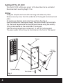
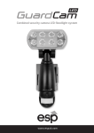
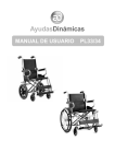
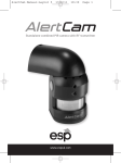
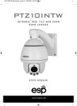
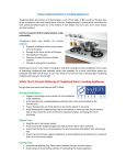
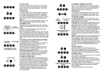
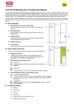
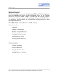
U SE R M AN UAL
2
Contents
EZ-LOCK
and Back Plate
1 x Security Torx Key
4 x Screws and raw plugs
Manual and
Marking out template
Equipment required for controlling one door:12 volt DC power supply 2 amp minimum (EV-BPS)
Lock - Magnetic (EVML-250)/Yale type keep 12 volt lock (enter D)
Push to exit button (EVEXIT)
Green break glass emergency release (EVEBG)
Note:- for use with Magnetic lock only
Functions of the EZ-LOCK
The EZ-LOCK can control up to two doors by use of pin numbers.
Selectable Pin number length 2,3,4,5 and 6 digits (per zone).
Programmable door open time 00 to 99 seconds.
Two locations (zone 1, zone 2) are available for programming pin numbers.
1000 Pins can be programmed for zone 1.
10 Pins can be programmed for zone 2.
Two volt free change over relays one per door.
Door closed function (contact required).
2 push to exit button inputs, one per zone.
Programmable volt free change over relay for door bell function.
Programmable rear tamper.
Internal buzzer for tamper monitoring (automatic cut off after 1 minute).
3
Sighting Of The EZ-LOCK
Site the EZ-LOCK within easy access to the door/doors to be controlled
Recommended mounting height 1.2m.
Fitting
Using the template mark and drill the fixing and cable entry holes.
Remove security screw from the underside of the keypad and remove back
plate.
Fit and secure the back plate in its final position. (See Fig. 1)
Feed the cable from the keypad though the centre hole of the back plate.
Clip the top of keypad onto the back plate and secure using the security
fixing screw located on the underside of the keypad.
Make all wiring connections and connect 12 volts DC to the keypad.
The green power LED will now be illuminated on the front of the keypad.
Screws
Screw
raw plugs
System wiring
Torx Screw
Fig. 1
4
Wiring Diagram and connections
Orange-push to exit button 1
Yellow-push to exit button 2
Additional power
supply for lock
5
Brief details of programming
Access To programming mode.
Selecting the length of the pin number to be used 2,3,4,5 and 6 digits.
Programme pin numbers.
There are two locations for entering pin numbers (zone 1 and zone 2).
Zone 1 has 1000 locations available 000-999.
Zone 2 has 10 locations available 00-09.
Select the lock release times (00-99 seconds) zone 1 and zone 2.
How to escape programming mode.
Note:- if no keys are pressed for 30 seconds the unit will drop out of
programming mode automatically.
How to enter and exit programme mode
To enter programme mode enter the 4 digit pin number twice (default pin
1234).
To exit programme mode press the # key.
How to set the length of the pin numbers to be used
Enter programming mode by entering the 4 digit pin number twice (default
pin 1234).
A Long bleep will be heard and the green power LED will turn orange.
Press the * key followed by the 9 key the orange LED will now flash.
Press 04 a long bleep will be heard.
Enter the length of the pin number you require (2,3,4,5 or 6).
If the length is the same as already programmed you will get a
conformation bleep.
If you have changed the length you will get 7 bleeps to say it has now
been changed.
Note:- Any pin numbers programmed into the system will be deleted if the
pin length is change.
6
Zone 1 programming
Programming a User Pin number to Zone 1
Note:- Zone 1 has 1000 locations available from 000 to 999.
Enter programming mode
A Long bleep will be heard and the green power LED will turn orange.
Enter the vacant location you want to programme the pin number in use a
3 digit format (xxx).
The green programming LED (top left of keypad) will illuminate.
Note:- if this location already has a pin number programmed the LED will
turn red.
To delete this location press the star * key twice. The LED will now turn
green.
Enter the pin number required, a conformation bleep will be heard.
If further pin numbers are to be programmed select the next available
location number (xxx).
Setting the Unlock Time for Zone 1
Enter programming mode.
A Long bleep will be heard and the green power LED will turn orange.
Press the * key then the 1 key the orange LED will start to flash
Enter the time in seconds for the unlock time from 00 to 99 seconds.
7
Zone 2 programming
Programming A User Pin number to Zone 2
Note:- Zone 2 has 10 locations available 00-09.
Enter programming mode
A Long bleep will be heard and the green power LED will turn orange.
Press the * key followed by the 4 key
The orange LED will start to flash
Enter the vacant location number you want to programme the pin number
in to (xx).
The green programming LED (top left of keypad) will illuminate.
Note:- if this location already has a pin number the LED will turn red.
To delete this location press the star * key twice. The LED will now turn
green.
Enter the new pin number required, a conformation bleep will be heard.
If further pin numbers are to be programmed select the next available
location number (xx).
Setting the Unlock Time for Zone 2
Enter programming mode.
A Long bleep will be heard and the green power LED will turn orange.
Press the * key then the 5 key the power LED will start to flash.
Enter the time in seconds for the unlock time from 00 to 99 seconds.
How to Change the Programming Pin Number
Enter programming mode.
A Long bleep will be heard and the green power LED will turn orange.
Press * key followed by the 3 key the orange LED will start to flash.
Enter the new programming pin twice.
A conformation bleep will be heard.
How to delete all pin numbers
Enter programming mode.
A Long bleep will be heard and the green power LED will turn orange.
Press * key followed by the 8 key the orange LED will start to flash.
Press the 8 key twice.
7 conformation bleeps will sound.
8
How to load factory default settings
Enter programming mode.
A Long bleep will be heard and the green power LED will turn orange.
Press the * key followed by the 8 key the orange LED will start to flash.
Press the 9 key twice.
One bleep will sound and the System will automatically come out of
programming mode.
How to Disable the rear tamper
Enter programming mode.
A Long bleep will be heard and the green power LED will turn orange.
Press the * key followed by the 6 key the orange LED will start to flash.
Press the 0 key followed by the 1 key.
The rear tamer is now off.
How to Enable the rear tamper
Enter programming mode.
A Long bleep will be heard and the green power LED will turn orange.
Press the * key followed by the 6 key the orange LED will start to flash.
Press the 0 key followed by the 2 key.
The rear tamer is now on.
How to Enable the door Bell function
Note:- If two doors are being controlled the bell function can not be used.
Enter programming mode.
A Long bleep will be heard and the green power LED will turn orange.
Press the * key followed by the 2 key the orange LED will start to flash.
Press the 0 key followed by the 2 key.
The door bell function is now on.
How to Disable the door Bell function
Enter programming mode.
A Long bleep will be heard and the green power LED will turn orange.
Press the * key followed by the 2 key the orange LED will start to flash.
Press the 0 key followed by the 1 key.
The door bell function is now off.
9
How to reset a lost programming pin number
Note:- this will set the programming Pin back to its default factory setting
of 1234 and leave all other settings intact.
Remove power to the keypad/reader for 10 seconds.
Apply power and press the # key within 3 seconds
10
11
Technical Specification
DC input
12 - 24volts
AC input
12 - 24volts
Standby current
80ma
Operating current (without lock)
110ma
Working temperature
-20c to +50c
IP rating
65
Dimension
152 x 45 x 25mm
Technical Support 01527 515145
Elite Security Products
Unit 7, Target Park, Shawbank Rd
Lakeside, Redditch B98 8YN
Telephone: 01527 515150
Technical Support: 01527 515145
email: [email protected]