1
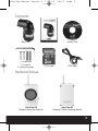
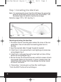
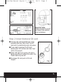
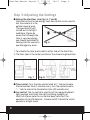
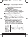
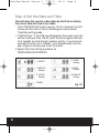
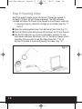
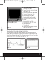
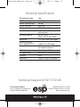
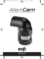
AlertCam Manual:Layout 5
17/8/11
18:30
Page 1
Standalone combined PIR camera with RF transmitter
AlertCam Manual:Layout 5
17/8/11
18:30
Page 2
IMPORTANT
IF IN ANY DOUBT ABOUT THE INSTALLATION OF THIS PRODUCT,
CONSULT A QUALIFIED ELECTRICIAN
I This product must be grounded
I Do not mount the unit against inflammable surfaces
I The motion detector will not operate correctly if it is installed:
1. Near the outlet of a central heating boiler
2. Near air conditioning
3. Pointing directly at moving vehicles (may cause false triggering)
4. Within sight of reflections from moving water (may cause false
triggering)
I Where other lamps could shine on the detector
BEFORE ATTEMPTING ANY INSTALLATION OR MAINTENANCE, ENSURE
THAT THE ELECTRICAL SUPPLY IS SWITCHED OFF AND THE CIRCUIT
FUSES REMOVED OR THE CIRCUIT BREAKER IS IN THE OFF POSITION.
Please make sure the voltage and polarity are correct before
connection. Incorrect voltage may cause electric shock. If you are
not sure, please contact your distributor.
Table of contents
Contents and Optional Extras . . . . . . . . . . . . . . . . . . . . . . . . . . . . . . . . . . . . . 3
Step 1: Installing the AlertCam . . . . . . . . . . . . . . . . . . . . . . . . . . . . . . . . . . . . 4
Step 2: Insert/remove SD card. . . . . . . . . . . . . . . . . . . . . . . . . . . . . . . . . . . . . 5
Step 3: Adjusting the Settings . . . . . . . . . . . . . . . . . . . . . . . . . . . . . . . . . . . . 6
Step 4: Set the Date and Time . . . . . . . . . . . . . . . . . . . . . . . . . . . . . . . . . . . . 8
Step 5: Viewing recorded or live footage via a PC. . . . . . . . . . . . . . . . . . . 8
Step 6: Viewing video . . . . . . . . . . . . . . . . . . . . . . . . . . . . . . . . . . . . . . . . . . . 10
Technical Specification . . . . . . . . . . . . . . . . . . . . . . . . . . . . . . . . . . . . . . . . . . 12
2
AlertCam Manual:Layout 5
17/8/11
18:30
Page 3
Contents
AlertCam
User Manual
Drivers Disk
1 x Allen key
2 x screws
2 x masonry plugs
2G SD card
USB Cable
Optional Extras
AlertCam RA
Remote chime alarm device
AlertCam RS
Remote 1500w switching device
3
AlertCam Manual:Layout 5
17/8/11
18:30
Page 4
Step 1: Installing the AlertCam
Note: It is recommend to mount AlertCam 2M above the ground for
optimum performance, do not mount the fixture below 1.2M.
See below figure for details of performance range.
Detection range: 10M x 160° (see Fig. 1)
Fig. 1
Mounting and wiring the AlertCam
1. To remove the rear mounting plate release the screw at the rear
underside of the unit and ease the mounting plate from its
housing
2. Feed the required cables through the glands supplied.
3. If AlertCam is to be used without a local lighting unit please see
wiring diagram Fig. 2.
4. If AlertCam is to be used to switch a local light unit (max 500w)
please see wiring diagram Fig. 3.
5. Ensure all wires are connected securely and that no loose strands
are exposed. Make sure the polarity is correct. Double-check the
connections after wiring. Errors may damage the motion sensor
or cause a fire hazard.
6. Please allow 1-minute warm-up time after switching on.
* Push the RESET button after switching on.
4
AlertCam Manual:Layout 5
17/8/11
18:31
Page 5
Fig. 2
BROWN - LIVE IN
NEUTRAL
Fig. 3
RED SWITCHED LIVE
Fig. 4
Important note:
Please remove the plastic
lens cover from camera
after installation.
Step 2: Insert/remove SD card
I Unscrew the waterproofed cover using
provided Allen key, then insert the SD
card until it automatically locks into place.
I If you need to remove the SD card,
please press OFF button and take it out
within 30 seconds.
I When LED light turns green, SD card is
being read, do not remove SD card at this
time or data may be lost.
I To remove SD card, push in SD card
to eject.
Fig. 5
5
AlertCam Manual:Layout 5
17/8/11
18:31
Page 6
Step 3: Adjusting the Settings
I Aiming the AlertCam (see Figs. 6, 7 and 8)
Alertcam has built in low energy laser device that can be used to
aim the camera at a the
optimal viewing area.
This operation is best
carried out in dull light
conditions. Please be
aware that although the
laser is very low energy
you should avoid directly
Fig. 6
looking into the source as
eye damage may occur.
1. To activate the laser press pads at either side of the AlertCam.
2. The laser spot is the center position of the camera angle position.
Fig. 7
Fig. 8
I Time control: Turn the time control knob to”+” side to increase
the illumination time (7 minutes max.), turn the control knob to
“-“ side to reduce the illumination time (30 seconds min.).
I Lux control: The lux control is used to set the required ambient
light required to activate the light switching capability of
AlertCam. Please note the Lux control does not effect the
operation of the PIR detector , Camera and RF transmitter which
operate in all light levels.
6
AlertCam Manual:Layout 5
17/8/11
18:31
Page 7
I LED indicator: The function status of AlertCam is indicated by
the following led colours.
1) Red: SD card is not inserted into the SD slot
or system is malfunctioning
or USB is inserted and connected with a computer.
2) Green: The unit is recording
3) Red Flash: The recorded files are deleting.
4) LED off: stand by mode when off/record button is pressed
Please note: when off/record button is pressed it is possible to safely
remove the SD card within 30 seconds. After removal
the LED will be red to show SD card is not present.
I Reset button: restore functions to default settings
1) Press RESET button once each time you turn on unit.
2) Please press this button in case of system malfunction.
I Off/Rec: Please press Off/Rec button to remove SD card. Please
remove card within 30 seconds of pressing the Off/Rec button to
avoid loss of data.
I RF Switch Code: The AlertCam has a built in RF transmitter
(approx 60m open field range) that can send wireless trigger
signals to the optional AlertCam RA (remote alarm unit) or
AlertCam RS (remote switching unit). The AlertCam will only
activate remote units with matching RF codes. All AlertCams and
remote units are factory set with the same RF code however
codes can be easily changed to avoid false triggering of adjacent
units. Remove
the white plastic
cover of the RF
switch and set
the switches to
either on or off.
To sync a
receiver set it's
four dip switches
to match that of
Fig. 9
the AlertCam.
7
AlertCam Manual:Layout 5
17/8/11
18:31
Page 8
Step 4: Set the Date and Time
This will allow the security video taken by AlertCam to display
the correct date and time it was taken.
Push TIME/DATE SET button (see Fig. 10) for 3 seconds, the LCD
screen will then flash 3 times, indicating you have entered
Time/Date setting mode.
1. “YEAR”setting: ”Y” and “08” are displayed on the screen; push the
button to set year from “08-99”, push the button again and hold
for 3 seconds to scroll through numbers quickly. If you have not
pressed the button for 3 seconds, it will automatically save the
year and go on to allow you to set the month.
2. Repeat the same setting procedure for
MONTH/DATE/HOUR/MINUTE.
1. START
3. MONTH
Setting
5. HOUR
Setting
FINISH
8
2. YEAR
Setting
4. DATE
Setting
6. MINUTE
Setting
Fig. 10
AlertCam Manual:Layout 5
17/8/11
18:31
Page 9
Step 5: Viewing recorded or live footage
via a PC or laptop
The PC will first need to have installed the bespoke drivers
contained on the enclosed CD.
To run correctly the minimum requirements of the PC should be
as follows:
I Windows 98/98SE/2000/ME/XP/Vista/WIN 7 (sorry, not MAC)
I Pentium III 450MHz or higher.
I 128MB RAM or higher.
I Display Card with 32MB RAM or higher.
I CD-ROM driver and USB Port.
I 2.5GB free hard disk space.
Installing the viewing drivers
I Insert the provided CD-ROM
I Locate the files on your PC
I Chose “ IP298X USB CAMERA”
I Follow the instructions on the installation screens
I If you computer doesn’t run the installation program
automatically, please click the “Start” button and choose “Run.”
Then browse your computer to find the file name under which
you saved the driver and click “ Setup.”
I Three files will appear after installation:
1. Amcap RTC: Live image
2. SDR View: Play the video
3. Uninstall: Remove the software
9
AlertCam Manual:Layout 5
17/8/11
18:31
Page 10
Step 6: Viewing video
AlertCam records images to the SD card at 2 frames per second in
sections of 20secs (ie a 40 frame sequence). The SDR software
included will allow the frames to be viewed as a continuous video clip.
1. Viewing image by computer through a card reader (see Fig. 11
and 12)
I Open the waterproofed cover from bottom of AlertCam (Fig. 11)
I Press OFF/REC button and remove SD card (part no. 2) from the slot.
I Put the SD card (part no. 2) into a card reader, connect PC and
card reader and open SDR View. Click “m” button to choose which
recording file you want to see the video then click “ f” or “g”
button to forward or backward playing the video. (Fig. 12)
Fig. 11
10
AlertCam Manual:Layout 5
a
m cde f gh i j k
Fig. 12
b
l
17/8/11
18:31
Page 11
a: Time scale selection when
viewing the video
b: Speed selection when playing
the video 1-8
c: Forward to previous file folder
d: Forward to previous file
e: Stop playing the video
f: Forward playing the video
g: Backward playing the video
h: Pause
i: Backward to next file
j: Backward to next file folder
k: Color selection
l: Time Search
m: Choose the recording file that
you want to view.
Viewing direct live video during installation
It is possible to view live images directly from the AlertCam to a
laptop during installation to ensure the camera is aligned correctly
using the enclosed AmCap RTC software. Connection must be made
using a mini USB – USB cable (See Fig. 9 & 13).
Fig. 13
Fig. 14
11
AlertCam Manual:Layout 5
17/8/11
18:31
Page 12
Technical Specification
PIR detection range
10m
PIR detection angle
160 Deg ( adjustable )
Camera viewing angle
60 deg
Camera resolution
640x480
Max direct load
500W ( 50W LED )
Camera controls
Automatic white balance
and exposure
Recording medium
SD (FAT16) or
SDHC ( FAT32 ) Max 64GB
Record rate
2 FPS for 20secs per trigger
Recording capacity
with supplied 2GB SD
1,000 files of 40 images
Image format
JPEG (converts to video stream
via bespoke software)
USB interface
Micro B type USB2
RF Trigger range
Up to 50M – Clear line of sight
IP Rating
IP55
Dimensions
108(D) x73(W) x138(H)mm
Technical Support 01527 515145
Elite Security Products
Unit 7, Target Park, Shawbank Rd
Lakeside, Redditch B98 8YN
Telephone: 01527 515150
Technical Support: 01527 515145
email: [email protected]