1
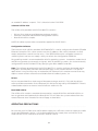
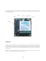
COPYRIGHT 2011 MicroBee Systems Corporation.
PCFW-104-ETH Long Range Ethernet Bridge PC/104 Interface
User’s Manual
CAGE Code 3DPE9
ALL RIGHTS RESERVED
However, any part of this document may be reproduced, provided that MicroBee Systems Corporation is cited as the source. The contents of this manual and the specifications herein may
change without notice.
TRADEMARKS
Windows® is a registered trademark of Microsoft Corporation.
ROM-DOS is a trademark of Datalight.
QNX is a trademark of QNX Software Systems, Ltd
......................................................................................................................................
MICROBEE SYSTEMS CORPORATION
1429 Weatherly Road, Suite G
Huntsville, AL 35803
Tech. Support: 256–489-6671
www.microbee-systems.com
[email protected]
1
NOTICE TO USER
. . . . . . . . . . . . . ............................................................................................. . . . . .
The information contained in this manual is believed to be correct. However, MicroBee Systems assumes no responsibility for any of the circuits described herein, conveys no license
under any patent or other right, and makes no representations that the circuits are free from
patent infringement. MicroBee Systems makes no representation or warranty that such applications will be suitable for the use specified without further testing or modification.
MicroBee Systems Corporation general policy does not recommend the use of its products in
life support applications where the failure or malfunction of a component may directly threaten life or injury. It is a Condition of Sale that the user of MicroBee Systems products in life
support applications assumes the risk of such use and indemnifies MicroBee Systems against
all damage.
Please read before installing your product
MicroBee’s products are designed to be high in performance while consuming very little
power. In order to maintain this advantage, CMOS circuitry is used. CMOS chips have specific
needs and some special requirements that the user must be aware of. Read the following to
help avoid damage to your card from the use of CMOS chips.
Using CMOS Circuitry
Industrial Control originally used LSTTL circuits. Because many PC components are used in
laptop computers, IC manufacturers are exclusively using CMOS technology. Both TTL and
CMOS have failure mechanisms, but they are different. This section describes some of the
common failures which are common to all manufacturers of CMOS equipment.
Improper power causes catastrophic failure
If a card has had reverse polarity or high voltage applied, replacing a failed component is not
an adequate fix. Other components probably have been partially damaged or a failure mechanism has been induced. Therefore, a failure will probably occur in the future. For such cards,
MicroBee highly recommends that these cards be replaced.
Other over-voltage symptoms
In over-voltage situations, the programmable logic devices, EPROM’s and CPU chips, usually
fail in this order. The failed device may be hot to the touch. It is usually the case that only one
IC will be overheated at a time.
Power sequencing
The possibility of failure can be caused by the external application of input voltage to the
radio via the external B+ input while the PCFW-104 power is off. If you apply 5V to the input
of a TTL chip with the power off, nothing will happen. Applying a 5V input to a CMOS card will
cause the current to flow through the input and out the 5V power pin. This current attempts
to power up the card. Most inputs are rated at 25 mA maximum. When this is exceeded, the
chip may be damaged.
Failure on power-up
Even when there is not enough current to destroy an input described above, the chip may be
2
destroyed when the power to the card is applied. This is due to the fact that the input current
biases the IC so that it acts as a forward biased diode on power-up. This type of failure is typical on serial interface chips.
Hot insertion
Plugging cards into the card cage with the power on will usually not cause a problem.
(MicroBee urges that you do not do this!)
However, the card may be damaged if the right sequence of pins contacts as the card is
pushed into the socket. This usually damages bus driver chips and they may become hot
when the power is applied. This is one of the most common failures of expansion cards.
PREFACE
. . . . . . . . . . . . . ............................................................................................. . . . . .
This manual is a guide to the proper configuration, installation, and operation of your PCFW104-ETH Interface. For setup and operation of the FreeWave FGRM Radio Modem refer to
the FreeWave Radio Users Manuals and Ethernet Addendum included with this product. You
can use your PCFW-104-ETH card in conjunction with other PC/104 expansion cards, tailoring
your system for a wide variety of applications.
This manual applies to operation and configuration of the PCFW-104-ETH interface only.
Please reference the FreeWave Radio Users Manual and Ethernet Addendum for radio configuration and operation. They are also available at http://www.microbee-systems.com/user_
manuals.htm.
TECHNICAL SUPPORT
. . . . . . . . . . . . . ............................................................................................. . . . . .
MicroBee Systems is committed to supporting our products. For this reason all FreeWave
User manuals as well as this manual are always available online in PDF format at http://www.
microbee-systems.com/user_manuals.htm.
This unit has been tested with a number of operating systems including MSDOS, Linux, QNX,
Microsoft Windows 98, NT and 2000. Any operating systems supporting an ISA legacy device
should operate normally with this product. MicroBee Systems does not guarantee operation
with unusual or custom operating systems.
If you have a question about the PCFW-104 card and cannot find the answer in this manual,
call Technical Support. They will be ready to give you the assistance you need.
When you call, please have the following at hand
•
•
Your PCFW-104-ETH Radio Modem Interface User’s Manual and the FreeWave Radio Users
Manual.
A description of your problem.
3
The direct line to Technical Support is 256-426-2431.
INTRODUCTION
. . . . . . . . . . . . . ............................................................................................. . . . . .
The PCFW-104-ETH is a 16-bit Ethernet Bridge interface module. The module is compliant
to Ethernet II and IEEE 802.3 10-Base-T and is compatible with Novell NE2000 in both 8-bit
and 16-bit operation. The module includes a built-in 10-Base-T transceiver, Serial to Ethernet
Bridge and a FreeWave FGRM-510X005 TTL Level 900 MHz Spread Spectrum Radio. Optionally a 1.3 GHz P501X005 Military/Export only radio can be fitted.
The Serial to Ethernet Bridge is a highly integrated ASIC that combines LAN and WAN subsystems to achieve a full Ethernet remote bridge. It automatically learns the MAC addresses on
the LAN it is connected to, and forwards only the frames destine for another LAN. This bridge
is placed between the RT8019 Ethernet controller and the FGRM Spread Spectrum radio to
form a highly integrated and compact Ethernet bridge for embedded applications and is fully
compatible with the FreeWave FGR-115RE Ethernet Bridge which makes an ideal master for
embedded systems networking.
The PCFW-104-ETH is supplied with a utilities disk that contains drivers for a wide variety of
networks and operating systems. An optional boot ROM lets you boot a remote PC/104 station automatically from a server making floppy and hard drives unnecessary.
Features
•
•
•
•
•
•
•
•
•
•
Fully compatible with the FreeWave FGR-115RE
Software Compatible with NE2000 on both 8-bit and 16-bit PC/104 slots
Compliant to Ethernet II and IEEE 802.3 10-Base-T
Jumperless operation
Supports Microsoft’s Plug and Play configuration for jumperless mode
8 Software configurable IRQ’s
16 Software configurable I/O address options
28-pin socket for Remote Boot ROM
93C46 Serial EEPROM for storing resource configurations and ID parameters
6 Diagnostic LED’s for LAN TX & RX, RS-232 TX & RX, LINK, Collision and Error status
Getting Started, Initial Configuration
The board should be fitted to the PC/104 stack. The PCFW-104-ETH is supplied pre-configured in jumperless mode, with the I/O base address of 0x340 and interrupt assignment of
IRQ5. To reconfigure the I/O, IRQ and operating modes please refer to the Software Drivers
section. The board is provided with a utilities disk containing drivers for a wide variety of
operating systems and netware packages. The disk also comes with a detailed help utility ,
HELP8019.exe, that will guide you through the installation procedure.
4
Radio Power
In order to provide maximum flexibility for the user the PCFW-104 allows for powering of the
Radio Module from either the PC/104 Bus 12 VDC supply or an external 6-30 VDC source.
PC/104 Bus Power
Place jumper JP2 in the INT position (jumper nearest PC/104 Connector).
The radio module is now powered from the PC/104 bus an no further connections are required. It is important to be sure that the 12 VDC bus power source has sufficient current to
supply the radio. It is recommended that the supply have at least 1.0 Amp capacity.
External Power
Place jumper JP3 in the EXT position (jumper farthest from PC/104 Connector). The radio
power now comes from terminal block J4. Note polarity! The positive terminal is marked with
a + and is the terminal farthest from the PC/104 Connector. Be sure to tighten the terminals
snugly.
The radio can be powered from any 6-30 VDC source such as vehicle power as long as the
source is capable of at least 1 Amp.
Caution
Observe polarity when powering radio from external power!
When using external power sources for the radio modem it is essential that the external
radio power and PC/104 stack be switched at the same time as described earlier in this
manual. It is recommended that if vehicle power is used the radio and PC/104 stack be
switched from the same master power switch. Powering the radio and not the stack could
potentially damage either the radio or the stack. Similarly, powering the stack and not the
radio can also potentially cause damage.
OVERVIEW
. . . . . . . . . . . . . ............................................................................................. . . . . .
The PCFW-104-ETH is based on the Realtek RTL8019AS Ethernet controller with Plug and
Play functionality. The RTL8019AS integrates the RTL8019 Ethernet controller core and 16
Kbyte SRAM in a single chip. A serial EEPROM is used to store resource configurations and ID
parameters. This is mated with a ASIC Ethernet to Serial bridge. Operation of the bridge is
transparent to the user and once the radio and Ethernet adapter are configured operation is
identical with a standard LAN port.
REALTEK RTL8019AS Ethernet Controller
The Realtek RTL8019AS is a highly integrated Ethernet controller that is used on the PCFW-
5
104-ETH to implement Plug and Play & NE2000 compatibility . The Radio and Ethernet adapter can be configured for Full Duplex. However, this is not recommended for the PCFW-104ETH. The full duplex function enables simultaneous transmission and reception on the twisted
pair link to a full duplex Ethernet switching hub. This mode of operation is only recommended
for the FGR-115RE when connected to a LAN Switch.
PnP and Jumperless modes
The Microsoft Plug and Play function frees the user from setting the PCFW-104-ETH configurations such as I/O and memory address and IRQ, etc. For certain applications Plug and Play
cannot be used. For cases such as these the RTL8019AS also supports jumperless operation.
In jumperless mode the configuration parameters can be configured using the RSET8019.EXE
utility provided on the utilities disk.
LAN Parameters
The LAN adapter should be configured for Half Duplex and Autodetect mode. Configuration
for Full Duplex is recommended only for switches and the PCFW-104-ETH cannot function as
a switch.
I/O addressing
The PCFW-104-ETH supports 16 base I/O addresses. The I/O address will be automatically
configured in a Plug and Play environment. In a jumperless system the module can be configured to any of the available address ranges shown below in Hex.
0x200 - 0x21F
0x220 - 0x23F
0x240 - 0x25F
0x260 - 0x27F
0x280 - 0x29F
0x2A0 - 0x2BF
0x2C0 - 0x2DF
0x2E0 - 0x2FF
0x300 - 0x31F
0x320 - 0x33F
0x340 - 0x35F (Factory Default)
0x360 - 0x37F
0x380 - 0x39F
0x3A0 - 0x3BF
0x3C0 - 0x3DF
0x3E0 - 0x3FF
The PCFW-104-ETH is supplied pre-configured in jumperless mode with a default I/O address
of 0x340h.
Interrupts
The PCFW-104-ETH can be software configured to generate interrupts on one of eight PC/104
6
interrupts. With Plug and Play systems this is done automatically. With jumperless operation
the IRQ number can be set using RSET8019.EXE. Available IRQ’s:
IRQ2/9
IRQ3
IRQ4
IRQ5 (Factory Default)
IRQ10
IRQ11
IRQ12
IRQ15
The PCFW-104-ETH is supplied pre-configured in jumperless mode with the default IRQ setting IRQ5.
Power Connections
The PCFW-104-ETH needs +5v and GND to operate. It also needs +12v for the radio. The radio
can be powered either from the PC/104 Bus 12V or by supplying externally from J1 6 VDC to
30 VDC.
These should be supplied to the board via the PC/104 connector. Ensure that the connections
for all necessary voltages are made to the baseboard or processor module.
Boot ROM
A boot ROM can be fitted to the PCFW-104-ETH so that it can boot directly from the network
instead of from floppy or hard drive. The socket allows 27C256 parts or equivalent to be fitted. The utilities disk contains sample ROM files and accessories that can be used to generate
a customized ROM file that can be written into the boot ROM part. These accessories contain
a ROMSUM utility that can be used to adjust the size of the ROM file to suit the boot ROM fitted.
PC/104 Bus Width
The PCFW-104-ETH module can be attached to either an 8-bit or 16-bit PC/104 bus. The module automatically detects whether it is connected to an 8-bit or 16-bit system.
Status LED’s
There are 6 LED’s on the module. These provide a visual indication of the status of the module
include LANTX, LANRX, 232 TX, 232RX, LINK, COL and ERR. The green LINK LED will maintain a solid green unless there is a issue between the onboard LAN chip and the LAN to Serial
converter. If the Link LED is not illuminated then the RSET8019 Utility should be run to verify
the RealTek 8019 is configured properly for Autodetect and Half Duplex. LAN TX and LAN RX
indicate LAN traffic to and from the Ethernet port to the Ethernet -> Serial Bridge. 232-TX
and 232 RX indicate communications from the Ethernet -> Serial Bridge to the FreeWave Data
Radio. During normal communications the LAN and 232 LED’s will flash at the data rates. The
RED COL LED indicated collisions on the network and can indicate excessive traffic. The RED
ERR LED indicates that the buffer is overflowing in the Ethernet -> 232 Bridge. This is caused
by very heavy traffic on the network. UDP traffic can also overflow the buffer very quickly
and UDP traffic should be controlled to reduce buffer overflow. If problems exist from excessive traffic a router can be placed between the LAN and the master radio to block traffic from
7
un-needed IP address’ or ports. This is identical to the FGR-115RE.
Software Utilities Disk
The utilities disk provided with PCFW-104-ETH contains:
•
•
•
Drivers for a wide range of Netware packages and OS’s.
Ethernet Controller and EEPROM Configuration utilities.
Boot ROM utilities sample.
NOTE: MicroBee Systems does not provide support for BOOT ROM’s
Configuration Software
There are two main utilities provided. RSET8019.EXE is used to configure the Realtek RTL8019
Ethernet Controller. This can be used to set the I/O address, IRQ, select jumperless or PnP
mode, and perform several function tests. If the EEPROM becomes corrupted contact MicroBee Systems and we can supply a utility to refresh the Configuration EEPROM.
Plug and Play mode is recommended for WIN 32 operating systems. Jumperless mode the IO
and IRQ assignments are manually assigned. WIN 32 operating systems can also be manually
configured for the PCFW-104-ETH by specifying the Base Address and IRQ.
Note: The software provided with the PCFW-104-ETH is used to configure the board and to
integrate it to third party netware software packages such as Novell Client32. For specific
applications it may be necessary to implement the Ethernet link in another manner that may
require custom written software not available from MicroBee Systems, Inc.
Drivers
Drivers are provided for a wide range of Netware packages and OS’s. To install the drivers
refer to the documentation for the Netware/OS and to the help utility HELP8019.EXE. There is
a detailed description on how to install all drivers within this file.
Boot ROM Utilities
The utilities disk contains complete documentation, sample ROM files and build utilities on
how to generate and implement the Boot ROM. This will allow the system to boot from the
remote Ethernet host instead of the local floppy or hard drive.
OPERATING PRECAUTIONS
. . . . . . . . . . . . . ............................................................................................. . . . . .
Be sure that your PC/104 stack and/or power supply has sufficient current to supply the radio
at the specified power setting. It is recommended that the supply have a minimum of 1.0
Amps for the 12 VDC internal or 8-30 VDC external source.
8
TECHNICAL SPECIFICATIONS
. . . . . . . . . . . . . ............................................................................................. . . . . .
Interface
Realtek RT8019AS 10 Base T compatible interface supporting Jumperless or Plug and Play
operations;
Data Rate
Maximum data through put is approximately 96 kbs in point to point mode. Actual throughput is a function of radio link and configuration.
Range:
20-60 Miles Line of Sight.
Environmental
-40° to 85° C operating.
-50° to 90° C non-operating.
RH 5% to 95%, non-condensing.
Power Specification
5V +/– 5% at < 75 mA max.
12V +/- 5% at 500 mA, Radio powered by PC/104 Bus.
8-30V at 1 A MAX, Radio powered from external source using J4
Size
3.6 in. x 3.8 in x 0.6 in.
91.4 mm X 96.5 mm x 15.2 mm
Radio Setup
In order to access the FreeWave Radio setup menus it is necessary to insert the diagnostic
cable in the connector on the radio. This connector is clearly marked as SETUP PORT. Pressing SHIFT-U (uppercase U) while in a terminal program such as Hyper Terminal will invoke the
user setup menu and allow the radio to be configured for the users network. Please refer to
the FreeWave Ethernet Addendum and the FreeWave Radio manuals for radio operation and
configuration.
Testing Installation
NOTE
Refer to the FreeWave Radio Users manuals for proper radio operation and setup.
9
Once the master/slave radios have been connected to their respective LAN’s data transmission should commence. Please refer to the FreeWave Ethernet Addendum for radio operation
and troubleshooting.

WARRANTY
. . . . . . . . . . . . . ............................................................................................. . . . . .
MicroBee Systems Corporation (MicroBee) warrants that it’s standard hardware products will
be free from defects in materials and workmanship under normal use and service a period of
one year from date of purchase. MicroBee’s obligation under this warranty shall not begin until Buyer returns the defective product, freight prepaid to MicroBee’s facility or another specified location.
MicroBee’s only responsibility under this warranty is, at its option, to replace or repair, free of
charge, any defective component part of such products.
10
LIMITATIONS ON WARRANTY
The warranty set forth above does not extend to and shall not apply to:
1. Products, including software, which have been repaired or altered by other than MicroBee
personnel, unless Buyer has properly altered or repaired the products in accordance with
procedures previously approved in writing by MicroBee.
2. Products which have been subject to power supply reversal, misuse, neglect, accident, or
improper installation.
3. The design, capability, capacity, or suitability for use of the Software. Software is licensed
on an ”AS IS” basis without warranty. The warranty and remedies set forth above are in
lieu of all other warranties expressed or implied, oral or written, either in fact or by operation of law, statutory or otherwise, including warranties of merchantability and fitness for a
particular purpose, which MicroBee specifically disclaims.
4. MicroBee neither assumes nor authorizes any other liability in connection with the sale,
installation or use of its products. MicroBee shall have no liability for incidental or consequential damages of any kind arising out of the sale, delay in delivery, installation, or use of
its products.
SERVICE POLICY
1. MicroBee’s goal is to ship your product within 10 working days of receipt.
2. If a product should fail during the warranty period, it will be repaired free of charge. For
out of warranty repairs, the customer will be invoiced for repair charges at current standard labor and materials rates.
3. Customers that return products for repairs, within the warranty period, and the product is
found to be free of defect, may be liable for the minimum current repair charge.
RETURNING A PRODUCT FOR REPAIR
Upon determining that repair services are required, the customer must:
1. Obtain an RMA (Return Material Authorization) number from the Customer Service Department, 256-426-2431.
2. If the request is for an out of warranty repair, a purchase order number or other acceptable information must be supplied by the customer.
3. Include a list of problems encountered along with your name, address, telephone, and
RMA number.
4. Carefully package the product in an antistatic bag. (Failure to package in antistatic material will VOID all warranties.) Then package in a safe container for shipping.
11
5. Write RMA number on the outside of the box.
NOTE
For products under warranty, the customer pays for shipping to MicroBee. MicroBee pays for
shipping back to customer.
Other conditions and limitations may apply to international shipments.
NOTE
PRODUCTS RETURNED TO MICROBEE FREIGHT COLLECT OR WITHOUT AN RMA NUMBER
CANNOT BE ACCEPTED AND WILL BE RETURNED FREIGHT COLLECT.
RETURNS
There will be a 15% restocking charge on returned product that is unopened and unused, if
MicroBee accepts such a return. Returns will not be accepted 30 days after purchase. Opened
and/ or used products, non-standard products, software and printed materials are not returnable without prior written agreement.
GOVERNING LAW
This agreement is made in, governed by and shall be construed in accordance with the laws of
the State of Alabama.
The information in this manual is provided for reference only. MicroBee Systems does not
assume any liability arising out of the application or use of the information or products described in this manual.
This manual may contain or reference information and products protected by copyrights or
patents. No license is conveyed under the rights of MicroBee Systems or others.
12
WWW.MICROBEE-SYSTEMS.COM