1
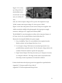
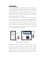
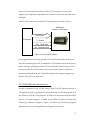
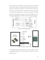
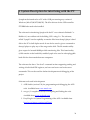
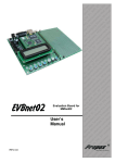
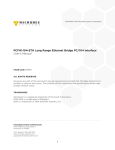
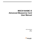
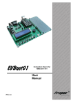
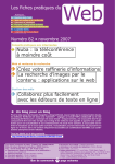
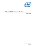
Symph: Portable mp3 player and hot pluggable
hard disk with network and USB interfaces
Vikram Dhar
566/ECE/99
Kshitiz Malik
625/COE/99
Electronics and Communication Engineering
Computer Engineering
Guided by
Dhananjay V. Gadre
Assistant Professor
M.P.S Bhatia
Assistant Professor
Electronics and Communication Engineering
Computer Engineering
NETAJI SUBHAS INSTITUTE OF TECHNOLOGY
NEW DELHI
2003
CERTIFICATE
This is to certify that the report entitled “Symph: Portable mp3 player and
hot pluggable
hard disk with network
and USB interfaces” being
submitted by Kshitiz Malik and Vikram Dhar to the Netaji Subhas Institute of
Technology, Delhi, for the award of the degree of “Bachelor of Engineering”
in Computer Engg. and Electronics and Communication Engg. is a record of
bonafide work carried out by them. They have worked under our guidance
and supervision and have fulfilled the requirement for the submission of this
report, which has reached the requisite standard.
The results contained in this report have not been submitted, in part or in full,
to any other university or Institute for the award of any degree or diploma.
Dated:
June 5, 2003
Supervisors:
M.P.S. Bhatia
Dhananjay V. Gadre
Assistant Professor
Computer Engineering
Assistant Professor
Electronics and Communication
Engineering
i
Acknowledgements
We would like to thank our guides, Assistant Professor Dhananjay V. Gadre,
ECE Department, NSIT and Assistant Professor M.P.S Bhatia, COE
Department, NSIT for all the help we received from them in the project.
Mr. Gadre was our infallible electronics consultant, we relied on him for
almost everything electronic, from critical soldering to tough-to-find
components, and most importantly, for advice. From interrupt levels in the
microcontroller to nuances of logic level conversion, he was a constant source
of solutions. We disturbed him at unearthly hours at times, and yet got
nothing but encouragement.
We also owe him for initiating us into the field of embedded systems a year
and a half ago through his evening lectures about the same.
Mr. Bhatia was very supportive throughout the project. From providing us a
lab to work beyond college hours to constant encouragement to publish the
design of the player, we are grateful to him for a lot of things. His guidance
during the numerous presentations and progress reports made throughout
the semester was invaluable.
We would like to thank our families for enduring our constant absence from
home over the past few months.
We are eternally grateful to R. Balaji of the NSIT ECE 2000 batch for the
numerous passive components he had “gifted” us from his ever diminishing
store, all in the hope that he’ll hear the circuit make music someday. Well
today it does.
Vikram Dhar
566/ECE/99
Kshitiz Malik
625/C0E/99
ii
Abstract
This report presents the design and implementation of Symph, a portable
mp3 player and hot-pluggable hard disk which has USB and network
interfaces.
Mp3 files are stored on a local hard disk, and a menu enables the user to select
and play music. The USB interface allows for file transfer from the PC to the
mp3 player and vice versa. A lightweight filesystem has been designed and
implemented for this purpose. The capability to read and write to an IDE
drive using the USB port implies that Symph can also be used as a hotpluggable hard disk for data transfer between computers, or as a data
acquisition system.
In addition to playing music from the hard disk, the mp3 player has a
network interface enabling it to play mp3 files from a file server. This is a
hitherto unexplored area, and had many possible applications.
iii
Table of Contents
Sno.
1
2
3.
4.
Topic
Page No.
Introduction
1
1.1
The rationale behind the project
1
1.2
Design Overview
3
1.3
Design Approach
4
Survey of Current Work
6
2.1
Standalone mp3 players
6
2.2
Portable mp3 players
6
2.3
PC-based mp3 players
6
2.4
Method’s used for mp3 decoding
7
2.5
Interfaces for mp3 players
7
Components
9
3.1
ATmega128 – The microcontroller
11
3.2
VS1001 – The mp3 decoder
13
3.2
FT232BM – The USB controller
16
3.4
The Hard Disk Connector
18
3.5
ISA Network Card
19
3.6
MAX8869: The power supply
20
Interfaces
22
4.1
ATA Hard Drive Interface
22
4.2
USB interface
24
4.3
ISA network interface
25
4.4
LCD interface
26
4.5
VS1001 Mp3 Decoder Interface
27
5.
System Description for interfacing with the PC
30
6.
User Manual
32
7.
Conclusion
35
8.
References
36
9.
About the authors
37
10.
Appendices
38
Data Sheet excerpts
-
Source code
-
iv
1. Introduction
1.1 The rationale behind the project
Mp3 (MPEG 1 Layer 3) provides excellent compression without a
corresponding loss in audio quality which has made it the most popular
format for digital music. As a result, portable mp3 players have a large
market which is growing exponentially as more people get initiated to the
convenience of digital music.
A portable mp3 player has the following important components:
1. An mp3 decoder: Decoding an mp3 stream is a complicated task
and must adhere to real time deadlines. Mp3 players use a
dedicated chip to perform this task. The decoder outputs PCM
samples which are fed to a DAC (Digital to Analog converter).
2. A data storage system: Standalone mp3 players must have the
provision to store mp3 files locally. This is usually accomplished by
using one among flash memory, hard disk, or CDROM . The system
must also have the ability to interface to a PC and transfer files to
the mp3 player, this usually involves writing software for the PC.
3. A microcontroller: There is a microcontroller at the heart of every
mp3 player. It interfaces to the mp3 decoder, the data storage
system, and the PC, and controls transfer of information between
them.
4. User Interface: This is needed to take inputs from the user (like
choosing which song to play), and for displaying song and system
information. It typically comprises of a keypad and an LCD (Liquid
Crystal Display).
1
An mp3 player is a real time system, since strict deadlines must be met in
mp3 decoding. This, coupled with the number of devices that the
microcontroller must interface with (mp3 decoder, data storage system, PC,
LCD, keypad) makes these systems highly complex. Therefore, building an
mp3 player is an excellent exercise in embedded system design. It needs
extensive knowledge of both hardware and software, which is why this is an
interdepartmental project.
Symph differs from existing mp3 players in two aspects:
1. It has a network interface which enables it to play music from a
remote file server. This has numerous possible applications. For
example, it could replace the CD players and audio systems present
in every room in luxury hotels, since it is better than these systems
in terms of both initial investment and user experience.
•
Initial Investment: The costliest component in an mp3 player
is the data storage system. Symph eliminates this cost, since
it can be “diskless”.
•
User Experience:
With CD players, users have a limited
range of music at their disposal. Symph will allow them to
choose from many gigabytes of music stored on a local
server).
Other possible applications include Symph Jukeboxes
replacing contemporary jukeboxes, once again providing
users with a wide variety of music to choose from.
The network interface that will be used in Symph can be reused in
other embedded systems that require network functionality with a
minimum of code rewriting.
2. Symph also implements the Hard Disk as a data storage device. It
could be used as a hot-pluggable disk for data transfer between
2
computers using regular hard disks. The file system developed and
the code written could be reused in data acquisition systems that
use microcontrollers.
1.2 Design Overview
The most important components of Symph are
1. Mp3 decoder - VS1001: This chip performs the mp3 decoding. It
also has an integrated DAC and directly gives analog outputs
2. Data Storage System – Hard Disk and Network: Symph gives the
user two media to play music from –
•
Local Hard Disk: Symph has an IDE interface which allows it
to read and write to a local hard disk. The USB interface
combined with PC side software provide the capability to
transfer files to and from the PC to the hard disk.
•
Network: Symph has the capability to play mp3 files from a
remote file server. It uses a NE 2000 compatible ISA network
card for this purpose. The card currently used is based on the
RTL 8019 chipset (belonging to a very popular family of
network controller ICs)
3. Microcontroller: The mp3 player uses ATmega128 as the
microcontroller,
which
belongs
to
the
AVR
series
of
microcontrollers made by Atmel. This microcontroller is powerful
enough, in terms of
•
Clock Speed
•
Number of I/O ports
•
Data memory
•
Program memory
•
UARTs and supported baud rates
3
to interface the components of Symph.
4. User Interface: Symph uses a 16 character, two line LCD and a four
button keypad for the user interface.
Figure 1.1 on the next page shows the design overview of Symph.
1.3 Design Approach
As with any complicated system, successful implementation of Symph called
for a modular approach. The system was developed in stages, each stage was
thoroughly tested and debugged before moving on to the next one. In each
stage, the hardware components and the interfaces were tested first using a
multimeter. Next, all the tests for the component (as specified in the
respective datasheets) were performed. Testing the full functionality of the
component was invariably the last part.
For example, when the mp3 decoder (VS1001) was integrated into the system,
the first step (after soldering the component) was to check the interface lines
from the microcontroller to VS1001. Individual lines of the microcontroller
were asserted and deasserted to check whether the interfacing circuitry was
working. The next step was checking whether the chip was “alive”, this was
done by performing analog tests on the IC. This was followed by basic
software tests in which a sine tone of a fixed frequency was played on the
decoder. Next came playing a small mp3 file stored in the microcontroller’s
flash memory. In the final stage of integration, VS1001 was used to decode an
mp3 file from the hard disk.
Such incremental design was necessitated by the complexity of the system
and the number of different devices that form part of the circuit.
4
Network
User
P.C.
The world
Symph PCB
Commands, eg
Play, Pause
Command and
Data
ISA Network
Card
Program Code
Data: For file (duringDevelopment)
transfer
USB Controller
In System
Programmer
Circuit
Commands, eg Data: For file
Play, Pause
transfer
Program Code
Push Button
Control
ReadReg
WriteReg etc
Hard Disk
ATmega 128
(The microcontroller)
Files Read
and Write
Mp3 Decoder
VS1001
Mp3 Stream
LCD
Display
Power Supply
(MAX 8869)
To all I.C’s
Figure 1.1: Design Overview
5
2. Survey of Current Work
The current digital media revolution will soon reach a point where standalone
mp3 players will become ubiquitous. Product development engineers and
home hobbyist continuously improve on their designs by adding new
interfaces and features to these players. A survey of the current design
techniques as done in [19] illustrates the following approaches to making mp3
players:
2.1 Standalone mp3 players
Feature mp3 decoding implemented in hardware or software and may have
local media for mp3 storage or functionality for streaming music over a
network. These only require an external power source for operation and can
be compared to Television set-top boxes. These kinds of players typically find
use in jukeboxes or for public broadcast.
2.2 Portable mp3 players
Same as above with the addition that they are portable and use low power
components and removable memory like Smart Media Cards (SMC), Compact
Flash or 2.5 inch hard drives. Flash based storage has a major advantage over
other designs due to absence of moving parts thus giving a sturdy and power
efficient design.
2.3 PC-based mp3 players
These players use PC based software for mp3 decoding and basically run as a
user application under the Operating system. The decoder is generally written
in high level language and compiled for the specific microprocessor. These
6
have zero portability and need the PC for their operation but may use
additional interfaces also.
2.4 Method’s used for mp3 decoding
2.4.1 FPGA with a DSP core:
This involves writing or porting a decoder for the DSP and using VHDL to
interface it with any additional components like DAC’s, LCD’s etc. These offer
no real commercial advantages in comparison with decoder IC’s and are
mainly useful for code development for that platform.
2.4.2 Mp3 Decoder IC’s:
These feature a complete mp3 decoding engine on a single chip with
interfaces for file input and music output. Some well known decoders are
STA013 by ST Microelectronics, VS1001K by VLSI Solution Oy. Most of them
feature a Serial Peripheral Interface (SPI) to accept an mp3 file serially from a
MCU. For output some of these use external high speed serial DAC’s like
STA013 and others like VS1001 utilise an internal DAC’s thus yielding a
design with fewer components.
2.5 Interfaces for mp3 players
2.5.1 Non volatile memory – As already discussed these use some kind of flash
memory like SMC etc. and mp3 players using these are of the most
commonest kind.
7
2.5.2 ATA Hard Drives – Hard Drives provide cheaper storage in comparison
with other media but need a robust power supply and have to be handled
carefully to avoid damaging the spinning media.
2.5.3 ATAPI CDROM’s – These have recently become popular because of the
decreasing costs of writable media but due to the need for large buffers to
give skip protection from mechanical shocks to the head assembly of the
player they are not fit for rugged use.
2.5.4 USB – The Universal Serial Bus(USB) is fast replacing legacy serial and
parallel ports from the PC and provides an excellent method for interfacing
low to medium speed devices to the PC. It also provides features like hotswapping and dynamic loading of drivers thus removing all inconveniences
faced while configuring older ports along with providing more than an order
of speed increase.
2.5.5 TCP/IP over Ethernet – The Ethernet (IEEE 802) today is the most
dominant networking standard and widely used for computer networks in
offices, educational institutions, libraries, hotels etc. The potential of Ethernet
based embedded devices is well understood by designers and this is
demonstrated by the large increase in number devices like sensors, electronic
appliances etc. being given hypertext interfaces [16] allowing their remote
monitoring and control. As brought out in the introduction networked music
players eliminate the need for local storage and provide a compact and
economical means for music broadcast.
8
3. Components
Symph is completely hand wired and has been built on a general purpose
circuit board made by joining two similar boards. All connections have been
made using heat resistant Teflon wire. A color coding scheme was followed
while wiring the board (Green wires for ground, Red for VCC etc). Most of
the components were available only as SMT (Surface Mount Technology)
chips, which made the soldering extremely tough. For example, the inter-pin
distance of the MAX8869 IC (power supply) is .65 mm, and this chip was
hand soldered on the board. Figure 3.1 below is a photograph of the backside
of the board. Figure 3.2 on the next page shows the front side of the board
with important components labeled.
Figure 3.1: Backside of the board
In this chapter, individual components of the mp3 player are examined. Their
novel characteristics are explained, and the reasons for choosing them are also
elucidated.
9
Clk (24Mhz) for VS1001
VS1001 mp3 decoder
74HC244 Octal Buffers
Earphone Jack
74HCT04 Inverter
Hard Disk Connector
ATmega128 uC
ISA Slot for n/w card
Reset Switch
Clk (6Mhz) for USB
Clk (16 Mhz) for ATmega
Max8869 Power Supply
5V for entire board
FT232BM USB Controller
USB Socket
Max8869 Power Supply
3.2V for VS1001
Figure 3.2: Front-side of the board
10
3.1 ATmega128 – The microcontroller
The heart of the mp3 player is the ATmega128 microcontroller, which belongs
to the very popular AVR family. Figure 3.3 below shows the position of the
microcontroller on the Symph circuit board.
Figure 3.3: ATmega128 on the board
Features relevant to Symph
•
Component Name: ATmega128, 8 bit RISC MCU
•
Function: Microcontroller, used to interface the various chips on the board
•
Manufacturer: Atmel
•
Packaging: 64 Pin Thin Quad Flat Package (TQFP)
•
Operating Voltages: 4.5 – 5.5V
•
Clock Input 16 Mhz
•
On chip program memory: 128k
•
On chip data memory: 4k
•
On chip EEPROM: 4k
•
8 external interrupts
•
32 General Purpose Registers
•
Byte oriented two wire serial interfaces: SPI (Serial Peripheral Interface)
•
Dual Programmable Serial USARTs supporting up to 2Mbps
•
53 Individually Programmable I/O Lines
•
Single cycle instruction execution using fetch-execute dual pipeline
11
Figure 3.4 on the left
shows a close-up of the
ATmega128 on the board.
On the right you can see
the ISP header which is
used
for
In
Programming
System
of
the
microcontroller using the
SPI interface.
Figure 3.4: ATmega128 on the board
The MCU is powered by a 5V supply provided by the MAX8869 chip.
Reasons for choosing ATmega128 as the microcontroller
1. Easy Availability: This microcontroller was available in the institute as
a free sample.
2. Development Software: The MCU is supported by a full suite of free
development
tools,
including
assemblers,
debuggers,
GNU
C
compilers, In System Programmers etc.
3. Development Community: The AVR developers community provided
a lot of support and help while building the project. Some parts of the
project used public domain code as the starting point.
4. Powerful Features: This microcontroller is powerful enough to handle
the complexity involved in the project. Specifically, since the number of
devices is very large, a large number of I/O pins with individually
programmable bits were required. Also, ATmega128 has single cycle
instruction execution, which when combined with the high clock
frequency (16 MhZ) provides the MIPS needed for interfacing the Hard
Disk with the mp3 decoder.
Another useful feature is that this MCU supports baud rates of up to
2Mbps which is useful while interfacing it with the USB controller
12
5. Previous Experience: The authors had used the AVR family of
microcontrollers before this project, hence, the development time was
significantly reduced.
Further details about the microcontroller are given in the appendix as
specified below.
Appendix A.1: Pin Outs of the MCU
Appendix A.2: SPI interface in ATmega128
Appendix A.3: USARTs in the microcontroller
3.2 VS1001 – The mp3 decoder
This IC decodes an mp3 bitstream to play music. It has an on-chip DAC
(Digital to Analog Converter), and has direct outputs for the earphone jack.
Figure 3.5 below shows the position of VS1001 on the Symph circuit board.
Figure 3.5: ATmega128 on the board
•
Component Name: VS1001, MPEG Audio Layer 3 Decoder
•
Function: Mp3 bitstream decoder
•
Manufacturer: VLSI Solution Oy
•
Packaging: 28 Pin Dual Inline Package (DIP)
•
Operating Voltages: 2.5 – 3.6 V , isolated analog and digital supplies
•
Clock Input 24 Mhz
•
4k program memory for user code
13
•
2k mp3 data buffer (FIFO, First in First Out)
•
On chip DAC
•
Separate SPI Interfaces for Data and Commands
•
Supports all valid mp3 bitrates, including VBR (Variable Bit Rate)
•
Stereo Earphone Driver capable of driving 30 Ohm Load
•
Supports PCM input, capable of playing .wav files
Figure 3.6 on the left shows a closeup of the VS1001 as placed on the
board. To the left of the chip can be
seen one of the 74HC244 octal
buffers which are used for logic level
conversion between ATmega128 and
VS1001.
The
mp3
decoder
is
powered by a 3.2 V supply from one
of the MAX8869 ICs.
Figure 3.6: ATmega128 on the board
Reasons for choosing VS1001 as the mp3 decoder
1. Easy Availability: This chip was available with one of our guides (Mr.
Gadre) as a free sample from the IC manufacturer.
2. Simple Interface: The chip supports the SPI interface for both Data and
Commands. This simplifies the interface of the chip with the
microcontroller, which also support the SPI bus.
3. Low Power: The chip consumes very low power, which is an important
feature in a portable mp3 player, since conserving battery power is
important.
4. On-Chip DAC: VS1001 has an onboard DAC, which eliminates the
need to use an external Digital to Analog Converter. The resulting
14
circuit is simpler, since the earphone jack can be connected directly to
the decoder.
5. Popularity: This IC is a component of many mp3 players. As a
consequence, there is significant amount of developer support for this
chip. The specifications are also very lucid, all of which helped in
speeding up the interfacing.
Logic Level Conversion
VS1001 operates at 2.4 – 3.6 V while the microcontroller operates at TTL
thresholds. This necessitated a logic level conversion circuit for the interface
between the decoder and ATmega128. The conversion uses a voltage divider
circuit along with an octal buffer (74HC244) as shown in figure 3.7 below:
= Buffer
AVR Output Port
AVR Input Port
1K
VS1001 O/P Port
VS1001 I/P Port
2K
Ground
ATmega128 to VS1001
Conversion Circuit
VS1001 to ATmega128
Conversion Circuit
Figure 3.7: Logic Level Conversion Circuit
15
Further details about the microcontroller are given in the appendix as
specified below.
Appendix C.1: Block Diagram and features of VS1001
Appendix C.2: SPI buses in VS1001
Appendix C.3: Package and Pin Description
Appendix C.4: SDI Oscilloscope Screen Captures
3.3 FT232BM – The USB controller
This chip is used to provide a USB interface connecting Symph to the PC for
file transfer between the two. Figure 3.8 below shows the position of this chip
on the Symph circuit board.
Figure 3.8: FT232BM on the board
Features relevant to Symph
•
Component Name: FT232BM, USB to Serial Converter (USB UART)
•
Function: Provide a USB interface for communication with the PC
•
Manufacturer: Future Technology Devices Ltd. (FTDI)
•
Packaging: 32 Pin Low Profile Quad Flat Package (LQFP)
•
Operating Voltages: 4.4 – 5.25V
•
Clock Input 6 Mhz
•
Full Handshaking and Flow Control Signals
•
384 Byte Receive Buffer and 128 Byte Transmit Buffer
16
•
Integreated 3.3V regulator
•
Baud Rates of up to 3Mbps supported
•
Powered from the USB connector wire itself
Figure 3.9 on the right shows a
close-up of FT232BM on the Symph
board. It doesn’t draw any power
from the board and is draws power
from the 5V line on the USB
connector itself.
The chip was available as an SMT
component,
which
made
hand
soldering difficult.
Figure 3.9: FT232BM on the board
This chip essentially is a USB to Serial Converter. It sends out the data it
receives from the USB port from the PC as a serial RS232 compatible stream.
This feature makes the integration of USB support in Symph as simple as
configuring the UART on the ATmega128 for serial data transfer. The only
difference from connecting the MCU to the FT232BM chip as compared to
connecting it to a serial port is Flow Control.
3.3.1 Flow Control in FT232BM
FT232BM uses two lines for flow control: RTS (Request to Send) and CTS
(Clear to Send). The chip asserts the RTS line when it is ready to receive data.
Before sending out data on the serial lines, it checks the status of the CTS line,
only if it is asserted does the chip shift out the data onto the serial line.
Reasons for choosing FT232BM as the USB controller
1. Easy Availability: This chip was also available with our guide (Mr.
Gadre) as a free sample
17
2. Serial Capability: The USB interface is greatly simplified with the use
of this chip since the microcontroller just needs to send data through its
UART after taking care of flow control.
3. Driver Support: The manufacturers provide excellent drivers for the
chip, greatly speeding up the development process on the PC side.
Also available is an API (Application Programming Interface) to
configure the device, and send/receive data from the device.
4. Baud Rates: The device supports baud rates of up to 3Mbps
5. Power Supply: This chip draws its power from the USB connector
itself, and doesn’t need to be connected to the power supply on the
Symph board. This reduces the power consumption of the mp3 player.
Further details about the microcontroller are given in the appendix as
specified below.
Appendix D.1: Package and Pin Descriptions of the chip
Appendix D.2: Schematic and Design Notes for the Bus Powered
configuration of the IC
3.4 The Hard Disk Connector
A hard disk connector is a very important component of the board. Figure
3.10 shows the placement of the connector on the Symph circuit board.
Figure 3.10: IDE Connector on the board
18
Symph can be connected to any hard disk that follows the ATA specifications.
This flexibility to connect to any IDE drive is a hitherto unimplemented
feature in mp3 players. Symph can also be used as a hot-pluggable hard disk
for data transfer. This is because Symph can be plugged into a running system
and files can be transferred to the hard disk without the need to shutdown the
computer.
Reasons for choosing a hard disk as the data storage device
1. Adaptablility: The mp3 player doesn’t specify the data capacity that
must be used. The user can decide as per his needs to use whichever
IDE drive of whatever capacity with the player.
2. Cost-effectiveness: The hard disk delivers the best ‘price per megabyte’
performance among all random access data storage media.
3. Universality: The hard disk is a ubiquitous component in the PC
world. Anyone using Symph will probably have access to a hard disk
which can be used to store mp3 or other files.
3.5 ISA Network Card – For the network interface
The ISA network card is used to provide network functionality to the mp3
player. Figure 3.11 below shows the ISA card being used on the Symph board.
Figure 3.11: RTL 8019AS ISA card
19
Features relevant to Symph
•
Component Name: RTL8019AS based ISA card
•
Function: Provide a Full duplex communication link with the ethernet
•
Manufacturer: Realtek Ltd. (RTL)
•
Packaging: 100 Pin Low Profile Quad Flat Package (LQFP)
•
Features both 8/16 bit interface
3.6 MAX8869: The power supply
Two of these chips are used to power the mp3 player. Figure 3.12 shows their
placement on the Symph circuit board.
Figure 3.12: MAX8869 on the
Features relevant to Symph
•
Component Name: MAX8869, Low Dropout Linear Regulator
•
Function: Power Supply for the 3.2 and 5V components on the board
•
Manufacturer: Maxim Integrated Products
•
Packaging: 16 Pin Thin Shrink Small Outline Package (TSSOP)
•
Operating Voltages: 2.7 – 5.5V
•
Dropout Voltage: 200mV at 1A
•
Resistor – controllable output supply
•
Guaranteed 1A output current
20
Figure 3.13 is a closeup of the position of
the MAX8869 on the
circuit board. As can be
seen, two of these ICs
were
Figure 3.13: MAX8869 closeup
used, one with an output voltage of 5V to power all components except
VS1001, another with output voltage 3.2 volts to power VS1001.
Figure x.x also shows the passive circuit of each of the power supplies. Also
visible towards the middle of the photograph is the input power supply
connector, which gets a 5V supply from a battery/SMPS.
The MAX8869 ICs were the toughest to solder, with a inter-pin distance of
0.65 mm. It took a lot of painful effort to hand solder these ICs.
Reasons for choosing MAX8869 as the power supply
1. Easy Availability: These ICs are available as free samples from the
Maxim website, and are shipped also free of cost.
2. Low dropout voltage: This feature is extremely important for any
portable battery operated system. The low dropout voltage reduces the
number of batteries needed to operate the mp3 player.
3. High Current Output: This chip can source up to 1 Ampere of current,
at a dropout of 200 mV. This large current value is required because
the startup current requirement of a hard disk is 900mA.
Further details about this chip are given in the appendix as specified below.
Appendix F.1: Features and Pin Outs of the IC
Appendix F.2: Pin Description and Design Notes
21
4. Interfaces
4.1 ATA Hard Drive Interface
Symph can interface to any ATA Hard Disk Drive which supports Logical
Block Addressing (LBA) for its sectors. It uses only 8 lines out of the 16
available for the data bus and thus supports full capacity in disk drives with
this feature only. All other disks are supported with half capacity. The ATA
interface registers are divided into two blocks and these are selected using the
active low signals /CS0 and /CS1 (see figure 4.1). Specific registers in these
pages are selected using the DA0-DA2 lines. The registers functions and their
address are given in appendix B. The host MCU can also hard reset the drive
by asserting the /RESET pin for at least 25usecs. The ports on ATmega128
corresponding to all these pins are defined in ata.h.
ADDRESS
ATmega 128
DATA 8 bit
40 Pin
ATA HDD
connector
R/W Control
/RESET
Figure 4.1: MCU to ATA HDD Interface
The HDD is a block device with the size of each sector equal to 512bytes. The
HDD sectors are read/write by following a programmed input/output (PIO)
read/write protocol as described using a flowchart in Appendix B.
22
For implementing this protocol we implemented functions to read and write
to HDD registers. These functions formed the lower most layer of the disk
interface and are called by all higher level functions like those for reading and
writing sectors. These functions are implemented in files ata.c and ata.h and
any other modules which need to call these should include ata.h.
The PC side software implements the file system and other functions like File
send and receive using a monitor running on the ATmega128. This monitor
offers the functionality in form of the commands shown in Table 4.1.
Table 4.1: Monitor Protocol Description
Command
1. Read Register
Code
0
Time >>
Register code
Send back value
2. Write Register
1
Register code
3. Reset Drive
2
Wait for ACK
Send back value
Send ACK
4. Read Sector
3
Send LBA
Receive Sector
Send Sector
5. Write Sector
4
Send LBA
6. Read File
5
Send start+end LBA
7. Write File
6
(in ASCII)
Send start+end LBA
Rx. Sectors
Tx. Sectors
PC
MCU
PC
MCU
PC
MCU
PC
MCU
PC
MCU
PC
MCU
PC
MCU
The filesystem layer and send/receive file interface for the symph when
connected to the PC is implemented by a Borland C++ builder based win32
application. This application uses the functions provided by the monitor to
implement a filesystem on the disk thus avoiding the overhead of the filesystem code on the MCU. However for standalone operation the MCU is
capable of displaying a list of files and then playing anyone of them according
to the users choice.
23
4.2 USB interface
The interface chip FT232BM is a serial to USB converter and is connected to
the PC using the USB port. On the MCU end it has lines for transmitting and
receiving serial data. These are connected to ATmega128’s 2nd UART. Thus to
the AVR the USB interface appears as a serial port. For the software on the PC
D2XX drivers available from FTDI give the programmer a standard buffer
read and write type interface to the USB port.
Flow control functionality was also added to the serial communication
interface using /RTS (Ready to send) and /CTS (Clear to Send) Hardware flow
control. These signals are provided by default on the FT232BM but have to be
software generated on the MCU side. The connections are made as shown in
Figure 4.2 and have to be cross connected. The Signal /RTS is asserted by a
device to indicate readiness to accept data and a device has to check whether
/CTS is asserted before transmitting anything.
Tx
UART
Rx
Rx
Tx
384 byte RX Buffer
128 byte TX Buffer
ATmega128
FT232BM
/RTS
/CTS
USB interface
to the PC
/CTS
/RTS
+
DD+
-
Lines for
Flow control
Figure 4.2: MCU to USB interface Lines
FT232BM has a 384 byte receive buffer and it keeps /RTS asserted as long at
least 32 bytes of space is available in this buffer. However since the
ATmega128 implements only a double buffered receive, therefore care had to
taken while receiving data on the MCU and /RTS should never be left asserted
when the application on the ATmega128 is not listening. However when a
24
application is expecting data continuously the overhead of asserting /RTS
after each byte can be avoided to maximize transfer rates.
FT232BM was used by us in a bus powered mode and the chip thus requires
no power supply from the board and automatically powers on when
connected to the PC.
The functions for initializing and using the USB interface are declared in usb.h
and this file needs to be included if the USB interface is to be used. The bit
rate for the serial transmission between the ATmega128 UART and the
FT232BM is limited by the MCU’s UART upto 2Mbps which is selected by
choosing the U2X Mode operation for the ATmega128’s UART.
4.3 ISA network interface
The ISA slot is used by the MCU to interface with a RTL8019AS NIC based
ISA Ethernet card. Only 5 address lines corresponding to those being used by
the Ethernet card are connected to the ATmega128. The data bus used is 8-bit
and these lines are shared with the hard disks data bus. Other signals needed
are /IOR and /IOW and a RESET.
ATmega 128
A0-A4 Address
8-bit Data Lines
8-bit
ISA
Slot
IO Read/Write
RESET
Figure 4.3: MCU to ISA Slot/Card interface
25
The network interface uses the free TCP/IP stack uIP developed by Adam
Dunkels [13] which is written completely in C. This stack has a very small
RAM base and is small enough to be fit on 8-bit microcontrollers. The code
footprint is of the order of a couple of kilobytes and the RAM usage is around
a few hundred bytes depending on the application. This is achieved by tightly
integrating the application with the protocol stack. The stack does not buffer
data to be sent and depends on the application to regenerate the data for
retransmissions. uIP also uses a event based programming model where the
application is implemented as a C function that is called by uIP in response to
certain events. A test version of uIP ported for win32 environment was tested
successfully in the Computer Engineering Project Lab. This setup involved a
server or a listening application incorporated with the uIP stack. The client
was coded in the Linux environment using BSD sockets interface and full
duplex communication was achieved.
The device driver for the interface between the protocol stack and the
RTL8019AS is based on Louis Beaudoin’s port of uIP for RTL8019AS chip.
This driver was written for the NIC as a discrete module and for a different
microcontroller of the AVR family and had to modified to ATmega128 and
the RTL8019AS based ISA card.
However problems were encountered while porting the code to ATmega128
due to the difference in clock frequencies for the 2 MCU’s. However after
addition of extra delay to the code for read and write register for RTL8019AS
the internal registers of the card can now be successfully read and modified.
4.4 LCD interface
The LCD used for the user interface is a GDM1602A manufactured by Xiamen
Ocular. This is a character based LCD with a built in controller. The display is
arranged in form of 2 lines of 16 characters each. Each character is displayed
26
using a 5x7 dot matrix based font with the 8th line acting as a cursor. The
display also incorporates adjustments for contrast and can also be used with a
backlight.
A MCU can be interfaced with the LCD using either 4 or 8 bits for data.
GDM1602A
Character LCD Display
8/4 bit Data
ATmega128
E - Enable
R/W – Read Write
RS – Data/Instruction
Figure 4.4: LCD to MCU interface
In our application to conserve pins the LCD will be interfaced in 4 bit mode.
The other interface pins are E, it enables the LCD interface and is the first step
before writing or reading from the LCD internal RAM. The RS line is used to
specify whether the current data is data or instruction. Reads or Write are
performed using the R/W pin. A brief description of the power supply pins
for the LCD is given in appendix G.
4.5 VS1001 Mp3 Decoder Interface
Symph is interfaced to the VS1001 using 8 lines. The SPI interface present in
ATmega128 is used to generate the clock and data for connecting the MCU to
the SPI lines of VS1001. The presence of SPI bus on the microcontroller allows
the use of a clock frequency of 4Mhz on the SPI bus. Figure 4.5 shows the
interfacing connection diagram. Figure 4.6 shows the connection diagram
separated into VS-to-ATmega128 and ATmega128-to-VS lines.
27
The return line from VS1001, DREQ, which is asserted whenever VS1001 has
32 bytes free in its buffer is connected to the INT0 line of the microcontroller.
This allows interrupt driven operation of the mp3 decoder. Whenever the
decoder asks for data, the INT0 line is asserted and an interrupt is generated
on the MCU. The interrupt service routine uses the SPI bus to send the
requisite number of bytes to the decoder. However, while DREQ is an active
high signal, ATmega128 has the capability to respond to low-level triggered
(B1)
(B2)
(B3)
PORTB0
INT 0
PORTB7
Figure 4.5: interfacing connections
SDATA [SDI]
DCLK
VS1001K
mp3 decoder
SCI
SCLK
ATmega128
BSYNC
XRESET
XCS
SO
DREQ
Figure 4.6: MCU to VS1001K interface
or rising/falling edge triggered interrupts (i.e, it cannot respond to a highlevel triggered interrupt). For this reason, DREQ is connected to the MCU
through an inverter.
28
The software routines used for interfacing with VS1001 are vs1001.c and
vs001.h (Appendix H).
29
5. System Description for interfacing with the PC
Symph can be interfaced to a PC with a USB port running any variant of
Windows (Win 95/98/NT/2000/XP). The d2xx drivers for the USB controller
FT232BM also need to be installed.
The software for interfacing Symph with the PC was written in Borland C++
Builder 6.0, an excellent tool for building GUI’s using C++. The software,
called “Symph” has the capability to transfer files from the mp3 player’s hard
disk to the PC in half duplex mode. It can also be used to give a command to
the mp3 player to play any of the songs on the disk. The file transfer utility
gives a speed of around 800Kbps while transferring files. This functionality
(of file transfer to the hard disk) enables Symph to be used as a hot-pluggable
hard disk for data transfer between computers.
The software also has a “low level” command section supporting reading and
writing of individual IDE registers, and raw read sector and write sector
commands. This can be used for further development and debugging of the
project.
Software tools used in development
1. AVR Studio (version 3.56) for programming and debugging the AVR
code. Available from www.atmel.com
2. avr-gcc (C compiler for AVR) for compiling and linking the code.
Available from www.avrfreaks.com
3. PonyProg for In System Programming of the AVR. Available from
http://www.lancos.com/ppwin95.html
30
4. Borland C++ Builder 6.0 Enterprise Edition to program the PC side
software for file transfer. For prices and availability, see
www.borland.com
5. Hyperterminal, a serial terminal program available free with Windows.
Used for initial testing and debugging of the system.
31
6. User Manual
Figure 6.1 labels the individual components of the Symph circuit board.
Clk (24Mhz) for
VS1001 mp3 decoder
74HC244 Octal Buffers
Earphone Jack
74HCT04 Inverter
Hard Disk Connector
ATmega128 uC
ISA Slot for n/w card
Reset Switch
Clk (6Mhz) for USB
Clk (16 Mhz) for
Max8869 Power
Supply
FT232BM USB
USB Socket
Max8869 Power
Supply
Power Supply Connector
Figure 6.1: Board Components
32
To play mp3 files from Symph, there is a hardware initialization routine and a
software initialization routine.
Hardware Initialization
(refer to figure 6.1 on last page for component placement)
1. Connect the “Power Supply Connector” in Figure 6.1 on the previous
page to a 5V power supply (from an SMPS or a Battery). Ensure that
the power supply doesn’t exceed 5.5 volts
2. Check the outputs of the two MAX8869 power supply ICs. The one on
the bottom (in Figure 6.1) should have an output of 3.2 volts, while the
one in the middle of the board should have an output of 5V. If this is
not the case, there is a problem with the power supply of the board
(refer to Appendix F for the pin outs of MAX8869)
3. Unplug the supply and connect an IDE drive (powered externally) to
the IDE connector (Figure 6.1)
4. Plug in the supply again, and check the output of the DREQ pin of
VS1001 mp3 decoder. (refer to appendix C for the pinouts of this IC).
This pin should be around 3.2 volts. If this is not the case, there is a
problem with the VS1001 interfacing circuit.
5. On pressing the “Reset” switch, check if the hard disk gets reset (the
motor of the drive can be heard when it restarts). If this doesn’t
happen, there is a problem with the hard disk interface.
6. Connect the USB cord to the USB socket in the board and plug the cord
into the PCs USB port.
Software Initialisation
1. Download the “d2xx” drivers for FT232BM for Windows from the
FTDI website (www.ftdi.co.uk). Unzip them to a convenient folder.
33
2. On connecting the USB cord to the PC, a “New Device Found: Serial <> USB Converter” message should appear. If such a message doesn’t
appear, or if the message shows “Unknown Device”, there is a problem
with the USB interfacing circuit.
3. When Windows asks for a device driver for the USB controller, specify
the path of the “d2xx” drivers of the FT232BM chip. Now the USB
controller is successfully installed.
4. Install the software “Symph” from the installation program
“setup.exe” in the installation folder.
5. After installation, run the software, and in the first screen, click on
“Configure”. If the configuration is successful, a message will appear.
Now you can successfully transfer files to and from the mp3 player,
and also play mp3 files in the player.
6. If the file transfer doesn’t work, you can click on the “Low Level
Functions” button in the main screen of Symph and try to debug the
software.
7. The code running on the microcontroller is given in a folder “AVR
Code”. This can be opened in AVR Studio (downloadable from
www.atmel.com) and can be edited.
8. To reprogram the board with the new code, connect the ISP dongle to
the parallel port of the PC and the ISP header of the Symph board
(Figure 6.1). Run the program Pony Prog (downloadable from
http://www.lancos.com/ppwin95.html), select the microcontroller
ATmega128 and program the device. The board can be programmed
“in situ”, i.e, nothing needs to be disconnected. However, after
programming, press the “Reset” switch on the board before doing
anything else.
34
7. Conclusion
The USB, ATA HDD interfaces were implemented successfully and work on
the network interface is in progress. The TCP/IP stack was successfully tested
and the device driver port for the network card is under testing.
MP3 playback was achieved in realtime without any buffering problems and
USB communications were optimized to achieve data rates upto 1Mbps.
35
8. References
1. VLSI Solution Oy’s VS1001K, MPEG Audio Decoder Preliminary,
http://www.vlsi.fi/datasheets/vs1001.pdf
2. Atmel’s ATtmega128 8-bit Microcontroller Data-sheet,
http://www.atmel.com/atmel/acrobat/doc2467.pdf
3. AVR In System Programming dongle Specification,
http://www.iready.org/projects/uinternet/ispdongle.pdf
4. Maxim MAX8869 Datasheet,
http://pdfserv.maxim-ic.com/arpdf/MAX8869.pdf
5. AT Attachment-3 Interface (ATA-3) Project Draft Specification, Revision 7b,
27 January 1997, http://www.t13.org/project/d2008r7b.pdf
6. FTDI’s FT232BM, High speed USB to RS232 converter preliminaries,
http://www.ftdichip.com/Documents/ds232b11.pdf
7. Atmel’s AT90S8515 8-bit Microcontroller Data-sheet,
http://www.atmel.com/atmel/acrobat/doc0841.pdf
8. Harald Leintner, Document on programming for AVR with GCC,
http://www.avrfreaks.net/AVRGCC/Download/haraleit.pdf
9. AVR libc Users Manual, http://freesoftware.fsf.org/download/avrlibc/doc/avr-libc-user-manual.pdf.zip
10. Website Content regarding avrgcc and avrstudio, www.avrfreaks.net
11. Gadre Dhananjay V., Programming and Customizing the AVR
Microcontroller, McGraw-Hill, September 2000
12. Realtek RTL8019AS specification, ftp://152.104.125.40/cn/nic/rtl8019as/spec8019(new).zip
13. Adam Dunkels, uIP documentation,
http://dunkels.com/adam/uip/documentation.html
14. Louis Beaudoin, uIP-AVR, http://www.embeddedcreations.com/projects/uipAVR.html
15. National Semiconductor DP8390D/NS32490D, Network interface controller
datasheets, http://www.national.com/ds.cgi/DP/DP8390D.pdf
16. Steve Freyder, David Helland, Bruce Lightner, “A 25$ Web server” http://i.cmpnet.com/chipcenter/circuitcellar/july99/pdf/c79blpdf.pdf
17. eAVR Project, http://www.avr1.org/eavr/hw_development.html
18. ISA Bus Technical Summary, http://www.techfest.com/hardware/bus/isa.htm
19. Website Content, www.mp3projects.com
20. Dhananjay V. Gadre, Programming the Parallel Port: Interfacing the P.C for
Data Acquisition and Process Control, CMP Books, Feb 1998
21. Xiamen Ocular’s GDM1602A Character LCD datasheet,
http://www.lcdchina.com/PDF/GDM1602A-5.pdf
36
9. About the Author’s
Vikram Dhar is a final year Electronics and Communications undergraduate
student at Netaji Subhas Institute of Technology. His interests encompass
microprocessors, wireless networking and system programming. He aims to
design the next generation of mobile devices. He can be reached by email at
[email protected]
Kshitiz Malik is a final year Computer Engineering undergraduate student at
Netaji Subhas Institute of Technology. He likes to read about all flavors of
Computer Architecture, and plans to be a doctorate someday. He can be
reached by email at [email protected]
37
10. Appendices
The Appendices are organized as follows:
Datasheets excerpts for A. ATmega128
B. ATA Specification
C. VS1001K
D. FT232BM
E. RTL8019AS
F. MAX8869
G. LCD
Source Code –
H. ATmega128 monitor sources
I. Borland C++ Builder sources
38