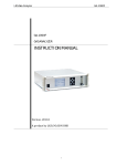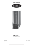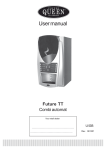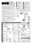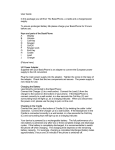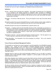
1
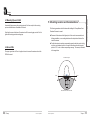
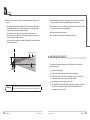
Omni Directional Antenna Unit 11 – 33 Riley Road – Woodmead + 27 11 612 3660 [email protected] www.gc-sat.com Installation Guide 1. INTRODUCTION 2 2. PACKAGE CONTENT 2 3. SYSTEM CONFIGURATION 3.1 Mechanical outlines * 3.2 Exploded View 3.3 System Connection Diagram 4 4 5 6 4. DESCRIPTION OF PARTS 4.1 Antenna Unit 4.1.1 Connector Interface 4.1.2 Power Supply 4.2 RF Cables 4.2.1 SAT RF Cable 4.2.2 GPS RF Cable 4.3 Mounting Pipe and U-Bolt 4.4 Ground Wire 7 7 7 8 9 9 9 10 10 5. MOUNTING LOCATION AND CONSIDERATIONS 11 6. MOUNTING PROCEDURES 13 7. SAFETY DISTANCE 18 In Strict Confidence Thuraya I www.thuraya.com Table of Contents Thuraya www.thuraya.com The appearance of each part is illustrated in the images below: 1 I Introduction This manual provides information on the installation instructions and environment, as well as usage of the ThurayaMarine Omni-Directional Antenna. The ThurayaMarine Omni-Directional Antenna is connected to the ThurayaMarine Terminal to provide stable transmission and receiving of Thuraya satellite signals and GPS signals for vessels that experience rolling, pitching, and yawing. Antenna Unit SAT RF Cable GPS RF Cable Mounting Pipe Bolts U-Bolt/Washer/Nut Ground Wire Installation Guide 2 I Package Content The ThurayaMarine Omni-Directional Antenna package includes the following parts: No. Item 1 Omni Directional Antenna Unit Max. EIRP : > +8dBW min. G/T : > -22dBk 1 2 SAT Antenna RF Cable 6.1Ø (Black), 12M, TNC (F)-TNC (F) 1 Silver Color 3 GPS Antenna RF Cable 4.95Ø (Black), 12M, TNC (F)-TNC (F) 1 Gold Color 4 Mounting Pipe 2.5” phi x 30 cm 1 5 Mounting Pipe Screw 4 5 6 U-Bolt /Washer/Nut 7 Ground Wire 8 Installation Manual I Thuraya Specifications Quantity Remarks 2/4/4 0.2M, Copper Wire 1 1 In Strict Confidence In Strict Confidence Thuraya I Thuraya www.thuraya.com 3.2 Exploded View 3 I System Configuration 3.1 Mechanical outlines * Top View Bottom View 190 110 233 150 X0 X0 Front View 63.5 Mounting Pipe * Unit: mm I Thuraya In Strict Confidence In Strict Confidence Thuraya I Thuraya 4 I Description of Parts 4.1 Antenna Unit 4.1.1 Connector Interface The antenna unit has two TNC female connectors at its base. One connector is the SAT signal port, and the other is the GPS signal port. www.thuraya.com 3.3 System Connection Diagram The SAT connector is silver while the GPS connector is gold. In addition, labels of SAT and GPS are marked over each connector to make distinction even easier. Maritime ANT (SAT/GPS) Connecting the RF cable with the SAT and GPS connectors is easy as both the colors of the SAT cable and GPS cable are silver and gold, respectively and the connection can be done by simply matching the colors. However, if the two connectors are switched and connected wrongly, the antenna will not operate properly. Wireless Handsat Dot for Mounting pipe Ext. Telephone Silver Color Gold Color GND wire screw hole Mani Unit & Handsat RJ-11 Port USB Port or DTE Port Dot for Mounting pipe G3 PAX Machine I Thuraya PC In Strict Confidence In Strict Confidence Thuraya I Thuraya Warning Make sure that the cables are not switched when connecting, as doing so will result in improper antenna operation. 4.2 RF Cables 4.2.1 SAT RF Cable The SAT RF cable is 12M in length and is fitted with a TNC male type connector at each end. Optional cables of lengths of 20M, 35M, and 50M are available for purchase from a dealer if excess of 12M long cable is required. www.thuraya.com At the base of the Antenna Unit, there are two projections and six screw holes. These are used when coupling with the mounting pipe. 4.1.2 Power Supply The antenna unit is powered by DC voltage from the ThurayaMarine terminal via the GPS RF cable. The ThurayaMarine terminal supplies DC12V power to the antenna unit. The DC voltage range that is operational for the antenna unit is +10Vdc ~ +15Vdc. Proper RF cable connection by the user can negate any need for concern regarding the power supply. Warning This antenna is designed exclusively for ThurayaMarine terminal. If connecting the antenna with a terminal other than ThurayaMarine, make sure that the input DC voltage is within the rating +10Vdc to +15Vdc (3 A). Otherwise, it may cause a fire or damage to the device. 4.2.2 GPS RF Cable The GPS RF cable is 12M in length and is fitted with a TNC male type connector and an SMA male type connector at either end. The TNC connector must be connected to the antenna unit, and the SMA connector must be connected to the GPS port of the ThurayaMarine terminal. If the RF cables used are non-authentic and unauthorized, voltage drops may occur in the RF cables due to the high electrical current (approx. 2.0A ~ 2.5A) consumed by the antenna unit. Therefore, producing and/or using any non-authentic, unauthorized RF cable is prohibited in principle as doing so can result in severe damage to antenna performance. Optional cables of lengths of 20M, 35M, and 50M are available for purchase from a dealer if excess of 12M long cable is required. Warning I Thuraya In Strict Confidence In Strict Confidence Only products that are authentic and/or recommended by authorized vendors should be used as RF cables directly impact antenna performance. Thuraya I Thuraya As essential fixing accessory, the mounting pipe and U-bolt are coupled to the mounting post on which the antenna is installed on the vessel. After fixing the screw at the base of the antenna to affix the mounting pipe, use the U-bolt to tighten the mounting post and mounting pipe. 4.4 Ground Wire The copper ground wire is 20 cm in length and is used to connect the antenna unit and the GND of the vessel. 5 I Mounting Location and Considerations The following precautions should be taken while installing the ThurayaMarine OmniDirectional Antenna to a vessel: Placement of the antenna at the highest point of the vessel is recommended, and following installation, no surrounding obstacles and/or objects should obstruct the view of the antenna. To allow the antenna to maintain communication capacity when the vessel is rolling orpitching, no obstacles should be in the path of the antenna from the horizontal position to -15° in order to allow corresponding coverage. This concept is illustrated in the image below. www.thuraya.com 4.3 Mounting Pipe and U-Bolt No Obstacles reguired Horizon -15deg -15deg Horizon Obstacles should be below shadow areas 10 I Thuraya In Strict Confidence In Strict Confidence Thuraya I 11 Thuraya ▪ The separation distance with HF antennas and VHF antennas should be at least 5 m. ▪ The separation distance with a Thuraya Tracking antenna or a tracking antenna made by another manufacturer should be at least 8m. ▪ The separation distance with the vessel’s compass should be at least 3 m. ▪ If the vessel is fitted with Radar, refer to the following diagram and make sure to establish a sufficient separation distance. ▪ In case of proximity to the radar is inevitable, ThurayaMarine Antenna unit must not be within the radar beam. Avoid installing near the vessel’s chimneystack. The smoke and soot emitted from the chimneystack can obstruct the signal level achieved by the antenna. The antenna unit should not be affixed to any steel panel that is wider than 190 mm square. It can cause performance degradations. Keep the unit away from heat sources. Do not install the antenna where flammable gases are stored www.thuraya.com Make sure that the antenna is placed at a sufficient distance away from any other antenna. Install antenna above this line 6 I Mounting Procedures PROHIBITED ZONE 2m PROHIBITED ZONE 15˚ The sequence of installation procedures for the ThurayaMarine Omni-directional Antenna is as follows. HORIZONTAL LINE Warning 12 I Thuraya When installing the ThurayaMarine Omni-directional Antenna, make sure to establish sufficient separation distances with any other antennas (VHT, HF, Radar, other tracking antennas, etc.). In Strict Confidence 1 2 3 4 5 Open the product package. Check to see that all contents have been included in the package. Decide on the location on the vessel for installation. Make sure to consider the considerations listed in section 5 during the selection process. Locally prepare an antenna mast with a ground stud. After passing the RF cables (SAT & GPS) through the mounting pipe, connect the connectors of the antenna unit with the RF cable connectors Make sure the connections are securely fastened. In Strict Confidence Thuraya I 13 Thuraya 14 After tightening the connectors, wrap the connections with self-bonding vinyl tape or apply silicon sealant to make them waterproof. I Thuraya In Strict Confidence After fitting the mounting pipe to the slot in the base of the antenna, tightly fasten the six bolts (M5 x 6ea). 8 Apply silicon sealant to the tops of the tightened bolts. In Strict Confidence Thuraya I www.thuraya.com 6 7 15 Thuraya Use the U-bolt to couple the assembled antenna with the vessel’s mounting pole (diameter of two inches recommended). Tighten the nut and make sure it will not become loose. 10 After tightly securing the ground wire to the ground wire-affixing hole at the base of the antenna via a bolt, tightly secure the other end of the ground wire to the mounting pole. Apply silicon sealant on the screw head. 11 16 I Thuraya In Strict Confidence 12 Fix the cable to the mast with cable tie.(local supply) 13 Tighten the SAT and GPS RF connector to the ThurayaMarine terminal. In Strict Confidence www.thuraya.com 9 Thuraya I 17 Thuraya www.thuraya.com 7 I Safety Distance The safety levels for the ThurayaMarine Omni-directional antenna units are based on the EMF Council Recommendation 1999-519-EC of ETSI (European Telecommunication Standard Institute). The recommendation will be maximum 8.3W/m2. Based on the above recommendations, the sufficient minimum safety distance is 40cm. Persons should not approach within 0.4meters of a transmitting ThurayaMarine antenna. Microwave radiation can be harmful to the human body. Warning 18 I Thuraya The minimum safety distance is 40cm. People should not approach within 0.4meters of a transmitting ThurayaMarine antenna. Microwave radiation can be harmful to the human body In Strict Confidence In Strict Confidence Thuraya I 19 Thuraya 20 I Thuraya In Strict Confidence