1
FILE NO.
Service
w
Manual
Cordless Telephone
Answering System
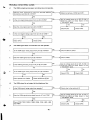
Contents
PRODUCT CODE
178 585 93
Specifications
..................................
1
Operation
................................... .. 2
Removal . . . . . . . . . . . . . . . . . . . . . . . . . . . . . . . . . . . . . 13
Tape Adjustments
Adjustment
............. ............... .
...................................
16
Voltages of lC and Transistor
(NZ)
No.
... ..................
49
... ... ... ...............
53
Schematic Diagram (Handset)
....................
Wiring Diagram (Main of Handset)
.. ...............
54
56
Block Diagram (Handset)
18
Block Diagram (Base Station)
25
Wiring
...............
60
.....................
26
........... .........................
27
Schematic Diagram (Base Station) . . . . . . . . . . . . . . . . .
Wiring Diagram (Control of Base Station) . . . . . . . . . . . .
62
64
33
Wiring
Diagram (OHM)
65
36
Wiring
Diagram (Main of Base Station)
40
Schematic
Exploded View (Handset)
........................
Exploded View (Base Station)
Parts List
CLA-I 380
lC Description
..... .. ..........................
Circuit Description
Troubleshooting
....... ......................
Guide
.. ....... ................
. .... ................
Diagram (Control of Handset)
.......... ................
Diagram (OGM &Control)
58
.. ............
66
...............
70
REFERENCE
No.
SM580489
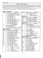
SPECIFICATIONS
●
CORDLESS
Transmitting
Receiving
TELEPHONE
●
frequency
ANSWIR]NG
Recording
Base station :30.075-30.300
MHz
Handset:
MHz
39.775-40.000
frequency
Security
. .....
yes
Announcement
......
yes
MHz
Noise Reduction
......
Super-Compander
......
yes (base station)
Extension
...... ..
10-number
Message
Channel Access
......
10-channel
Security
......
Codes
Continuous
Standby
.. .
2141
Auto message erase
Handset:
(Manual scan)
.
Delay
3 (Factory preset)
yes
Handset Remote
Dial
.....
......
MHz
Speaker Control
Memory
Control
Base station :39.775-40.000
UI
Micro Cassette
Codes for
Toll Saver/Ring
30.075-30.300
........
System
Remote
..
*
SYSTEM
..
only
Phone disconnect
Recording
Voice Activated
Time
yes
.
Recording
10 million
Calling Parity control
1-week
remote control Functions
auto
max 3 minutes each
yes
......
.. .
ON / OFF
AUTO REW / PLAY,
OGM CHANGE,
Auto Standby I
Quick Talk Access
yes
AUTO RESET,
Intercom
...... ..
yes
REVIEW ,
Paging
.... ....
yes
FAST FORWARD,
Flash
... .....
yes
TURN ON / OFF,
Instant Tone
. .......
yes
and ROOM MONITOR
Ring level control
Hearing-Aid
Wall-Mountable
●
.....
Compatible
yes (handset and base station)
yes
... ...
yes
GENERAL
c STANDARD
Power Source
Local current with AC adaptor
AC 230-240
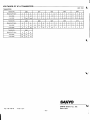
Digit
V I 50 Hz,
Handset:
.
1
697
697
697
770
770
770
852
852
852
1209
941
1209
941
1336
941
1447
5
172( W)x53(H)x227(D)mm
Handset:
58( W)x205(H)x50(D)mm
6
7
8
.........
9
Base station :
694 g ( without adaptor )
Handset:
265 g ( including
..
..
batteries
0
x
#
)
AC adaptor and plug adaptor
Telephone
line cord
Wall mount Hanger
Instruction
manual
Microcassette
Number
Tape
Memory
index Sheet
Battery Pack
Specifications
Frequency
3
4
Ni-Cd battery :3.6 V, 270 mAH
Base station :
Accessories
TONE
(Symbol)
2
DC9V
Weight
DIALING
. ..
Base station :
Dimensions
DTMF
subject to change without notice.
–l–
(Hz)
1336
1477
1209
1336
1477
1209
1336
1477
OPERATION
u
Thank you for purchasing the Sanyo CLA-1360AUS.
The Sanyo CtA 1360AUS IS a cordtess Iefeptmrm and answering system in
one comnact umt and has manv convenient features.
. . .. .—. lGChannel
.
.
.
.
Access - If noIsa or other intetierence occurs during a
convemsfion, press the SCAN twf’fon to select a dtiemnt chennel. (See
psga 20.)
10-Number Auto Dial - You can store up to 10 frequently cslled numbsrs
for easy recall. Ones storad, these numbers can be daled by using the
MEMORY button and the O-9 buttons on the handset. (Sss page 22.)
Intercom
Using the handset and base station, you can have an intercom conversatmn. (See pages 25- 26.)
Outgoing Message (DGM) IC Recording - Your outgoing message,
which asks callers to leave a messege, is recorded on an integrated
cmcutt. This allows callers to I&ve a mesaege immedatefy after hearing
your outgoing message, instead of having to weit for the message tape to
wmd to the end of the last recorded massage.
Your outgoing message is also ramrded at the b@nning of the message
tape as a backup. If there is a power failure, the outgoing message is
transferrsc automatically from ths mes.ssga tapa 10 the IC memory when
the power is restored.
Remote Message Retrieval - You can ratrieve your incommg messages
fmm another Iocstim using any touch-tone telephone whch has a
“continuous tone” signal. (See page 33.)
Switchabln TonwT%dse Dfalina - The CLA-1360AUS can be operated
on tone or W*
d~lng system;. When used with puke daling telephone
tines, you can dial a number, then switch to tc+w dinting temporarily to
access answering machines by remote control, or to access special
tefephfma smvices swh as elecfromc banking.
This SANYO cordless tetephondanswering
bla.
system is Haattng-Ad
compafi-
NOtka
This unti uses rsdio communication between the handset and the base unit
afwl may not ensure privacy of communication. Ofher devic%s, includlng
other cordkss telephones, may interfere with the opersfiin of the cordless
telephone sectiin of ths unti or csuse noise during operation. Cordlass
telep4mas must not cause interference to any Ihcenssd radio sewice.
fnterfemnca
If you have more than one cordtess telephone in your home or otfii, we
recommend that you separate the telephones from each other aa much as
possible to avoid inteflem.
If interference does occur, change the operating channel on one of the telephones by pressing the SCAN button, or lower
the base sfatii antenna, thareby reducing ifs range.
J!==J!
Rechargeable battwy
. Charge the rechargeable battery for a full 12 hours before using the
cOrdfess telep~ne for the first time. (Sea psge 8.)
. Clean the bsffery charging terminals on the handset and tha base statiin
once e month by wiping them with a soft cloth moistened Iiihtly with
isopropfl akolml.
.sOcUrffy code
This cordless tefepnone nas a digital security ayatem with 10 miltiin poasibfe
tine
codes. This system helps to prevent unauthorized use of your te!epbne
by another cordless talephona.
If you hear a high-pitched beep tone, or no dial tone, ths means that ths
security ccda has been fost. If this occurs, reset the security coda ss described onpagell.
. If a power failure occurs, or H the battmy is mplacad, tha security @We
must ba reset. (Sea page 1 1,)
operating
range
The operating range may vary depencfhg on the operating condkions,
location and distancs between the base stafiin and the handset. For the
bast possibk perfonnatw,
locate the base stafiin in the highest mom
feasible in your home or office, and as close to the centm of the desired
opsrafing area as possible.
For the best performance under normal operating cmdiimns, extend the
base station antanna fulfy.
Since cordless telephones use radm frequencies for communtition,
certain
cbstaclea between the base station and tfw handset may reducs the operating range.
The following are some examples.
- Concrete wal!5
- Tile walls (fypiilly used in bathrmma)
- Lsrga metal cbjecfs (such as refrigerators, metal cabinets, etc.)
Metal shielding inside of walls
- Metal fences
- Ob@ts whch obstruct radio frequencies
NOTE: If you are beyond the cperafing range of the tetaphona, the END
btdton or SCAN bunon does not operate propdy. If this occurs., move closw
to the base station and try again.
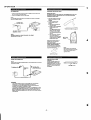
INSTALLING
THE BAITERY
PACK
1. Remove the battery comparf
ment Id.
Plug the baftery pack cord into
tha connector insida the banery
mmpmtment. Plsce the bsftefy
psck in the battery
2’ compartment.
Noise
Electrical pulse noise is present in
~~~~~=.:~helectrical
storms. Certain kinds of
electrical equipment such as TVs,
fluorescent Iampa, hslogen lamps,
microwave ovens, light dimmers,
motors, fans, ate., also generate
ndsa pulses. Secsusa rado
freauarwv tt-ansmissms are
sus&pd&a to these pulses, on
-ion
you msy hear ttwm in
your handset. Generaliy they area
mi~r annoyance and atmutd not
be inte!pretad as a dafacf in your
system.
Plesse read these hints carefully to get the best performance from your
cordless telephone.
@
+?
3. Replace the M by sliding it up
over the pack until fi is fhmiy in
place.
A
NOTES
- When you repla.x ftw banery
pack, press the END buttcm
before step 1 shove.
If the bstfery psck is reptaced,
the semhy code and any
sfomd numbers am c!eared.
- When yw repface the baftety
pack, pull out the plug of battety
pack verficalfy.
e
fNSTALLING
THE ANTENNA
Antenna
Install the antenna to the handset by
rotating if clcdwise as shown.
For the beat overall performance the
telescopic rod antenna ia
recommended. Using the optional
robber antenna may reduce
p%rfonnarwe and operational range
–2–
Handset
OPERATION
t!
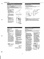
AC CONNECTION
CHARGING
1. Insert the small plug on the end of the AC adaptor cord Into the 9V DC
lack on the back of the base stat!on.
Plugthe ACadaptormto
an ACwalloutlet.
IMPORTANT NOTE:
The battery pack must ba charged for a full 12 hours before the cordfass phone is used for tha first fima. Do not use the phona before
charging the battery pack.
2
NOTE:
If 6 long beeps sound when the AC connecfiins are made, the message
tape has not been inserted.
1
THE BAITERY
PACK
Place the handset on the base
station and charge it for a f!l!
IaQurs.
2
To power outlet
(AC241JV, 50fiz,
<
~~-~
~+s’
<,,~~
/’
v
‘o-
U’
H
/
------
I?_lp<
AC adaptor
(Model No. KR0617)
NOTE:
USE ONLY SANYO AC ADAPTOR
(APPROVAL NO. Q941 13)
,)
/z
*
MODEL NO. KR0617
In order to verify that the
handset battery is fully
chsrged...
a) Remove the handset fmm
the base station.
b) Check to see that the BAIT
LOW mdlcator IS off.
NOTE:
If the BATT LOW indcator
hahts. even after charaina
f;r a full 12 hours, ref;r t;
the troubleshooting guide on
page 41.
c) After initial setup, recharge
the handset banery by
placing it on the base station
cradle whenever the BAIT
LOW indmator hghts.
>*
//
.
%
‘&
BAIT LO
mdcator
Replacement banery packs are
available from an authorized
Sanyo service center.
ReDlacemmt bafferv mck D@
nUkbOC SANYO 3N~2”70W”
Use of other brand or type baner!es may cause serious damage or
equipment maituntilons.
:.
NOTE;
When batteries are discharged,
they must be disposad of in a safe
manner that compbes wdh all
applicable laws.
6
SANYO 3N-2701W
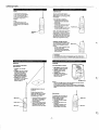
PHONE LINE CONNECTION
NOTE:
Please make sure fhst the handset battery is fully charged before connecting
the phone line cable.
BASE STATION VOLUME
CONTROL
Set the VOLUME control to the
correct poafin to give you the
desired sound bvel. If you set the
VOLUME control to the minimum
position, no sound is heard fmm
the speaker.
qiL3
WARNINGS
- This cordless telephone may, on some longer fines, have difficuiiy
handing over to another devk mnr!%cted to the same fine.
- Immediately disconnect the equipment should it become physically
damaged, and arrange for its disposal or repair.
- The operation of this equipment on the same line as telephones or other
equipment w~h audible warning devices or automate ring detectors will
give rise to tefl tinkle or noise and may causs falsa tripping of the nng
detector. Shou!d such ptilems
occur, the user is not to contact Telecom
FauRs Service.
–3–
l,.
mm–
,/
VOLUME
control
OPERATION
SECURfTY CODE
The CLA-I 380AUS has a digfial security system with 10 milhon pessible
codas. Th!s system helps prevant the unauthorized use of your telephone
Ihneby another cordleaa tefephans war.
A aecunfy code ia sat aufomafiilly the first time the hamleet ia placed in tha
basa station cradla When the coda is sat, a bep sounds.
Tha eecunfy cccte must b reset if the battery pack is raplaced or the powar is
interwptad.
WALL MOUNTING
(if dasirad)
To mount the basa station on a wail
1. Inaaf the heals of the hangar in the holes in the back of the base sfahon.
Then push tham in the diracfion of arrow @as shown.
.o
P
2. Connact tha cord.
3. Mount tha basa station on the wall
How to reset your security coda
1. Place the handset m the cradle
of the base station.
2. Press the PAGEilNT button on
the base station (wtihin 3
aaconds). A baap sounds wlthm
30 saconds. Tha sacunfy code
is now sat.
To socket
+
?,,”’
-l!
wall
[>*k,,
,,
>
To change your sacunfy ccxfe
at any time, simply repaat the
above steps. A new sacurify
code IS automal!aliy set each
time.
/;
~
A
.)2
NOTES
- It is nacas-sary to change the
Wcurify Cede it
. There is a pewar failure.
● The baffary pack is changad.
oTha battery pack is exhausted.
. The AC adap+or is dkconnacfed.
- If fha sacurify coda has bean
claarad, talk cannot ba made
until the coda IS met.
Wall-mount
hanger
NOTES:
Ths cordless tefaphone may not be compafibfa with carfain mUlfip18 lit18
PBX systama.
Avoid Imatwns near ekfrical aquipment such aa computers, Ns,
flwraacant lamps, halogen Iampa or microwave ovans. Thesa may
causa mterferenca or reduca the operating range of the cordless telaphone.
NT
u
ANSWERING
button
SYSTEM
RING DELAY SWfTCH
(2/4/AUTO)
The RING DELAY switch lets you
choose the numbar of times the
telaphone rings before a call IS
answerad
2 position
Incommg calls are answerad on
the sacond ring.
- 4 pilstion:
Incommg calls are answarad on
the fourth ring.
AUTO (Toll Savar) position
The first incoming call is
answerad on the fowfh rfng,
and later calls are anawerad on
the sacond ring. If you call your
numbar from anothar phona
and hear threa rings, you know
you have no messages and can
hang up and save the cost of
the call. When you reset the
unit to the auto answar mode,
the unit again answera the fitat
new call on tha fourth ring.
RING DELAY switch
CPC OWOFF
The telephone systems in many
areas provide a disconnect puke
when a caller hangs up. If the
CPCIANS.ONLY
switch (Imatad
on the side of the basa station) is
sat to CPC ON, tha CIA-13S0
stops racording and returns to the
auto anawer mode when this
dkconnecf puke ia raceivad This
eliminates annoying recodings of
dial tonaa between meaaages.
The CPC/ANS.ONLY switch
should ba kept in the CPC OFF
position it
- Your telephone is aquIppad
with call waiting sarvke
- You have a noisy telephone
exchange
(If the switch is not in the CPC
OFF position, your calls may ba
disconnected prematurely.)
ANSWER ONLY
If you do not want massagas to ba
raceivad and racordad, sat the
switch to the ANS.ONLY peaiion.
The unil then plays your outgoing
massage but doss not record
iktcoming messages.
CPWANS.ONLY
switch
–4-
RECORDING AN OUTGOING MESSAGE
Safore you racord your outgoing message, dwde
and write il down.
what you are going to say
SAMPLE OUTGOING MESSAGE
“Hello. Th#s IS (your nama). Please leave your nama and teL@wne number
and a brief messaga, and your ca// wi// be retumad as .xxM aa Po.saible.
Thank you. ”
NOTES:
The message tape must b-s
insertad before an outgoing
message can be racordad. This
enauraa that them is a backup
tape racordhg of your outgoing
meaaage in the event of a powar
failure. (Sea “POWER FAILURE”,
page 40.)
- If you anempt to record an
outgoing message without a
message tapa insertad, 3 long
bsaps sound.
- Your outgoing message can ba
up to approximately 16 saconds
in length. The IN USE ind~tor
flashes to alert you during the last
4 saconds of racording fima.
If you anempt to racord an
outgoing message more than 16
saconds In length, the answaring
system automaocalty stops
racording and enters the auto
answer mode
When outgoing messaga recorrlng la complatad, the unit swtches to the auto answer mode
automatwally. If you want to
cancal the auto answer mode,
press fhe STOP button.
If an mcommg call is recaivad
while you are rawrdng your
outgoing messaga or while the
backup tapa racordmg IS being
made, your outgoing massage IS
erasad. If thts happans, racord
your outgoing mesaaga again.
- When you replace the message
tapa, you must racord your
oofgoing message again.
1. Press the STO~ bu~on.
–
2. Sal Ihe VOLUME control to the
mid position.
3. Press and hold the OGM REC
button for approximately t
sacond until a beep sounds.
The IN USE indicator fights.
4. When you haar the baap tone,
rscord your messaga using the
bunk-in mwophore.
5. Press the OGM REC button
again to end recording.
The IN USE and ANSWER
indicator flash affemately, and
your outgoing meseage plays
back automafiially. (A backup
racmding of your outgoing
message is made automatically
on the message tape.)
~icrophone(MIC)
OPERATION
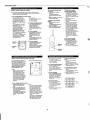
E@9u
Allmlna
MEMORYButton
pressto
phOmnumb+.
store
sl.nwd@one n.nbr,
\\
7
/
mrnmwycftomcda
(see page2’2)
RINOERSwNch
T.ms W ting.3ron ad off.
TMsswitchnwstbasetmsm
\
onpmilim
inwdsrluarhg
/
mbeheardwmrlm
REDIALIPBun..
Pressto rdld he Ih$t
“umberd,aled IfWI press
my otier dmlmgbutton
More pmsmg m,. bum”, !t
furcticiuas a pauseMton.
(3wp~~~,228 23)
NT (I”twcorn)Button
Pressto beginm merccm
mnwrsaiim WM Umbase
-.
DTccadng
cd is r.3c81ved.
Wne”hsnilch issettolln
(Swpagmashza)
ofl FQMICO,me nng w -.
\
o
?5
\
TALK Indimtm
Li.#ltswhenm.s-iskl
talk&
Flaslms*
theanswering
sptem ISm use.
reJyt0tTsp9s.lem)
,,
.. ..
Flashesnilen tlw answering
system M use.
(Zee W@ 31.)
is
\
~
~
‘\
‘TK
REMOTEButton
Pm6sbanwlawnm
-dng
Sysm fm tie
-.
(SW PEW31.)
/
END Button
Pres la ~
!@
~m B*”
Presstochangeme channel@f
ycuImarnom or mterfereme
dulirlga call,(s.. page20 )
\ mcrOpAOM
Commx Pd”m
FcMt.mwy packcharging.
.
TGtAE(++)Bultan Pras.910_Ub9d4aVq
-~~w
tobme.(s00 @gn 23.)
Gld~ Buttons
Umwliketfwkalmsnna
stemdadTOwh-TCn9-.
RINGGELAVSwhch
(2WAUTO)
W to 2 to have 0341sawmmd on w
sm
nng
Sdt04@kcaNs
answered0n!lw
fcwlflmg.
Se! 10AUTO10settoTdl Savermode
(see PW8 13.)
ModularTdep4m”eJack(TEL UNE)
(see page9 )
\
BACK OF UNIT
OGM (Out@ng MmsuIP) REC Button
Pressm recmi yourculgmngrrwssags
(See ww 14.)
ERASEButtm
Pressto wmn m==w$ ~.
m+ die, -*
tnmOn-w
mm.
(2.aapages29&30)
\
I
I
ACAd@wH
Jack(GS 9V)
(Seepage7 )
RINGERSwitch(OFF/LOIlfl)
Adi.slstie VC4.nw.1the base
swum rmgmWhensetto
OFF,w n.g ISheard [If. call
s recewecdumg m ,ntercorn
c.mversabonthe nng(sheard
even if the RINGERsw,tch,s \\
CFWANS.ONLYswitch
Fornormsuse,settoCPC ON If W fMVe
EASYCALLservicew a ndsytdephme
excha~, set10WC OFF,
Ify do notwantb ,s...
messages,set
toANSONLY (-SW., rely). (SW We 13)
/
VOLUMEControl
Musts me souti levelfrcmU-mbase
.*”ho. speaker(See page10.)
PAOEIINT Button y
R69s m b8#. m mtercm comer.
Smimwlmme h%ndwtuser.
Am wd toresetw cmdles9
tehphmn sacumycode
(SeaPaWest1,25&2C.)
BOTTOM VIEW
‘o-”
-ml
w-w
.
B-a
~
.
J’
Rmte AccessCode Number Label
@e.3Pa,..)
Jno
,——
—.––
,Dl
–5–
MieroP&
(MC)
/
ANSWER
Indkmu
LI@WS
‘WW”tie h n mtie
wI. answermcd+
Flastmsto mdhxtem nurnhar
of messqes (iIldudklg—)
remkd (10a nwknwn of 15)
OPERATION
w
BEFORE
;;;
m
Spnkef
POWERIndkatw
@hlsw4mnliwu’nt Isw@iedwfh AC
v~.
/
\
;A..
-....:....:::.
::.*..*.:.
..
~::;
~.;$..
.. ... ...
~
. ...%....
. . . . . . ..% . . .. .. .. . . .
$. ?.::.. }... .... .. .. .. .. ..
. . . . . . . . .. . .. . . . . . . .
. . .. . .. .. .. . %..: ;::
. . ... .. .. ... .
.... .. . .. ... .
Ill IE==I
/
-#
Fw c@nmmW—
avefbcalFcmlcm
e, extendhMYIn
‘X%”--”-s
yPullml to reed
S@msd ,“—.
%
MAKING
A CAU
1. Fully extend tha antenna on fha
bass station.
2. Take fhs handaat to ths desirad
Iwation.
3. Fully esfend ths antenna on the
handset.
4. Press the TALK button. Make
sure that you gaf a dial tons
and the TALK indiitor fights.
5. Make a call.
6. Press the END button to ratum
the handset to tha standby
mcxte.
.—~tud
. !=FwO(Fast Forward)Button
Presstofast-forward
tie -90
(see $a@ 30.)
taps.
- REWf+ldnd) Button
PTe3storerdn dnmmess.swtalm
(3e3pag03J)
, MEMO REC Bunon
Pressto recorda -
[Ssspaw 3S )
NOTE:
If the phone doss not work propw
Iy, chack the system connactiins
and the oparatmg rangs. (If the
BATT LOW indwator IS It, charge
the handset.) Saa page 8.
1O-CHANNEL
ACCESS
The CLA-1360AUS is cspabfa of
0psr2fing on 10 dfierant channals
If you expafiance interferancs
during a call, simply salad a
dfierant channel by prassmg the
SCAN button.
(Seep%%
‘a 8W.)
-
END button
000
\[nq
TALK indicat
‘1
TALK button
NOTE:
Wfwn there is excaaaiva signal
rmisa or interferanca, pressing ths
SCAN bufton may not impmvs
signal quatii. If conversation
bacomes impossible, Iol!e+vthe
lnstnmbons t@3w
1.
2.
3.
4.
Place the handaat in ths cradfa of the base ststion.
LIff the handsat and press the END button.
Press ths SCAN button.
Reaat the sacurifv ccda. (%s oa9e 11.)
Fo=o)ll
r
SCAN bunon
PLACING
A CALL
1. Press the TALK button (or pick
up the hsndset from tha bsse
station). The TALK iticator
Ihghts
2. D[al the number YOUwant to
call
If you make an error in dlafing
the numbar, press the END
button, then press the TALK
button to get a dial tone.
3. Press the END bunon to hana
up (or return the handset to t;e
base stabon crsdla).
AUTO STANDBY
Affar ftmshmg a call, you csn hang
up by returning the handsat to the
base station cradle The handset
automaocally swtches from talk
mode to standby mode. Thn
feature lets you use the handset
hke a regular corded telephona
(without pressing the END button).
To answer the nexl call, simply
pick up the handset and talk.
NOTE:
When you ramove the hsndsat
fmm the baas ststion cradls, tha
phone automatically enters the tslk
mode. (This means that H someone tries to call you tha MIWwill ba
busy.) To return to sfsndby mcde,
press tha END bunon.
ANSWERING
CALL
AUTODIAL
AN INCOMING
t.
Press the TALK button (or pick
up the handast from the base
station). The TALK indcator
hahts.
2. T;lk.
3. Press the END button to hang
up (or return tha handset to ths
base station).
NOTES
If the RINGER swtch IS set to
the oft postbon, no ring is heard
when an i?coming call is
rscawad.
The cordless handaet may ring
slightty after a corda4 telaphons
connectad to the ssme phona
Ime.
If the handsat is too far away
from the base stabon, prassing
the END button may not hang
up a call. If this happans, come
closer to tha base station and
press ths END bunon, or return
to the bass station and place
tha handsat in the base station
cradle.
END button
TALK button
Diafing bufton
—’
‘6”6 -d
Oocj
1;0 o ~
,$00
.-=-.:
$
You can stora up to 10 fraquentfy cslfad phona numbars in the auftiial
memow. Storad phone numbara can include oauses whera nacassaw. (Saa
MOW.;
To store numbers
1. Press the END button.
2. Press the MEMORY button.
The TALK indwator flashaa.
3. Dial the phone numbar you
want to store.
4. Press me MEMORY button.
5. Press a number button to
designate an index number (O-
-
9).
A baap sounds. The phone
numbar IS now storad in the
autodial memory.
6. Write the storad phone number
on the suppfii index shaat.
7, Repaat steps 2-6 above to
store other numbars or to
changa previously storad
numbara.
- To interrupt numbar storing.
press the END button any time
before step 5 above.
- To clear a storad phons numbar from the memory, press the
END button once and then the
MEMORY bunon hwce and
enter tha indax numbar (O -9)
of the phone numbar you want
to c!ear.
To call a number stored in the
memory
1. Press the TALK button.
2. Prass the MEMORY bunon.
3. Press the assigned index
numbar (O-9).
NOTES
- To inaart a 2-sacond pause
bahvaan two digts In a storad
numbar (after 9 to get an
outside Ihnem a PBX system,
for exampla), press ths
REDIAUP button after tha first
digit.
9
REMEMBER:
Your handset banefy naads recharging when you haar a baap avefy 3
saconds during a conversation. (Tha BAIT LOW indwtor also lights.)
–6–
-
Phone numbers up to 16 digits
in length can be storsd. (A
pause counts as one digit.)
The aulodial memory is clearad
It
. The banety pack is changad.
. Tha banery pack is
exhausted.
TA’Ki”’”’t”’-lL2i%
II
a
00
0
MEMORY
button
REDIAUP
bultcm
00
(?00
\ —
.
OPERATION
,
FLASH SUITON
II
REDIAL
You can use the FLASH button to
access special services offered by youI
phone company (call waiting and PBX,
for example).
To automatically radal the last
number called, press the REDIAIJ
P button instead of dialing the
number again. (Phone numbers up
to 32 dlgds in length can be
mdialad.)
If you subscribe to call watiing,,.
1. If a call comes in when you are
aheady on tha pfume, an audible
tone sounds.
2. Press FLASH.
The first call is placed on hold, and
you can talk to the second caller.
3. Press FLASH again.
The swond caller is placed on hold,
and you can talk to the first caller.
A(( “’’” )).
I
‘1
NOTE:
To radal after hearing a busy
signal, press the END button, then
the TALK bunon, then the REDIAU
P button.
1,<] [.>
oc)~J 0.
ig:~l
NOTE: The FIASH button may also be
used to get a new dial tone without
prassing END or replacing the handset
in the base station cradle, However, If
your telephona line has special service
features (like call wamng), tha FLASH
button may rot operate in this way.
HANDSET VOLUME CONTROL
If it is difficuil to hear tha cal lets votia
during conversation, prass the TALK
button owe to ikwease the volume.
NOTES
. To return to the normal Ibvel, press
the TALK button again.
- The racaiving !evel automatically
resets to the normal level when the
call is terminated.
REMEMBER:
Your handset banery neada recharging when you haar a beep evety 3
seconds during a conversatmn. (The BAIT LOW indcator also hghts.)
INTERCOM
INTERCOM
From handset to base station
(Auto Intercom)
From base statban 10 handset
1. Sa80daUcw
Press tha PAGE/
NT bulton to page the handset.
2. Handset Press the TALK
button and begin intenx+n
conversafiin,
3. Hand8et: When intercom
conversation IS ovar, press the
END button to swtich Ow
intercom mode off.
1. Hand8et Press the END
buffon.
2. Hand8et Prass tha INT button
to page tha base stafiin. The
baae stafiin automatically
switches to intercom mode.
3. Handset and bna station
Bagin intercom conversafiin.
4. Handset When intenmn
conversation is ovar, press tha
END bulton to swnch tfw
intercom mode off.
I
PAGE/lNT
button
VOLUME
a
tml
NOTES
- When the VOLUME control on tha basa atatmn k sat to the minimum
postfIon, no sound is haa~ fmm tha speaker.
- If the handset uaar does not answwr, tha basa station is aufomafiilly
dmnecfad
appmximafaly 5 secmda after ycu refa~
the PAGE/lNT
button.
II
INTERCOM
ON HOLD
WHILE A CALL LS
H
During a tel~one
call, the
handset user can talk to the base
sfafiin war. fThe oufsii call is
aufomafiiliy
put on hold.)
4
END button
..—
(( ,,,,, );
,.
fi]
TALK button
~:o–ali
fNT button
100
6.0$’
1000’
11.,e ,.
Room monitor
The handsat user can monitor the
ambient sound of tfw mom wham
tha base afafiin is l-tad.
1, Prass the END txdfcm.
2. Press tha INT button to begin
monitoring.
3. Press ffw END button to and
montiotfng.
- Gwaring the handsat mouthpkca whii monitoring may
produce Imffer sound quafii.
1. Prass fha NT button to abti the
baaa stafiin. (Tha outside call
is put on ho!d and the TALK
indiitor flaahas,)
2. If you end tha intercom cOnversatii or the basa sfaticm dces
not answar, press the TALK
button to talk to the callar again.
II
1
,’
;)
\
ENO button
1+
~ +.,’
I
~,o=~
k
:: ‘
11221 INT
i
button
/ ‘,,
R
–7–
,’,
e 0/
OPERATION
“w
BEFORE
WHEN A CALL COMES
YOU LEAVE
1. Make sure there IS enough
space Ien on the message tape
to record your calls If there IS
not, rewind the tape or turn it
over and reinsert It.
2. Press the ANS SET bunon.
The ANSWER lndmator lights,
and your outgoing messaga
plays back automatically. The
answering system IS now ready
to racewe calls.
NOTES:
- If you furn over or change the
message tape, you should
record your message again.
(ThiS Wltl r-d
a backup
message as described on page
14.)
II 6 long beeps sound when you
press the ANS SET button, no
outgoing massage has been
recorded
IN
The answering system answers all calls and records all messages to a
maximum of three mmutes each. If you do not wmh to record any messages,
sat the CPCIANS.ONLY
swttch to ANS.ONLY.
NOTE:
If the end of the message tape is reached while a message IS bang recorr$
ed, 3 long beeps sound.
,.—
L
[~g$$j,
. .=..
.,,,..,..,,
\
:::-..
.=:.
.Ay.+),..,,
.,..
...::,:..,..,
.,.,Y,T,:.:.,
..$::,.
.
-u
ANSWER
mdcator
.
TAPE END ALERT
If 3 long beeps sound and the
ANSWER indwator flashes slowly
when you press the ANS SET
button. there is not enough space
left on the message tape to record
calls (or the tape has not been
Inserted).
WHEN YOU COME HOME
CALL COUNTER
The ANSWER lndcator flashes to
mdbcate the number of messages
that have been recewed (to a maxi.
mum of 15). If more than 15 messag
es are recewed, the lndlcator flashes
continuously.
/“
L
ANS SET bunon
@
NOTE:
If the end of tha rfwssage tap+?IS
reached whtfa a message (or
memo) IS being racorded, the
ANSWER ihdiiator flashes slowly
and continuously. If this happens,
you cannot perform “AUTOMATIC
PLAYBACK”. Before proceeding
wth manual message playback,
press the STOP button, and then
press tha REW button.
To erase messages manually (Fast Erase)
1. Press the STOP button
f
2. Prass the ERASE button and hold
it.
3. While holding the ERASE button,
press the REW button.
The answering system beghx to
erase the messa~ tape.
The FFWD bulton does not
function for faat erase.
\
i;;+::,.
z-: y:;:<,.::...,
:*...>.:....,::.},
;:$.~:::+j,.,,.:::..,
....:.:,:,::;,:,:.:::,.:,:!:::,
[
L’=C.
-
‘–.
. .
AUTOMATIC
PLAYBACK
w
hk
REW
button
STOP
button
ERASE button
1. Press the PLAYBACK button.
The answering system plays
back any recorded messages
(Including memos).
2. Then you can:
a) Repeat message playback
b) Save messages
c) Erase messages
a) To repeat messages playback
Press the PLAYBACK button
The unit plays back any recorded messages.
MANUAL
PLAYBACK
The message tape can be advanced or rewound to quickly find a ce!tam
message or recorded sacfion of the tape.
t.
\
O
Press the STOP button.
Thn disengages the unit from
tha auto answer mode and lets
you use it like a ragular tape
recorder.
2. Press the PLAYBACK button.
The massage tape begins
playing back.
3. Press and hofd the FFWO or
REW button to quickfy mcwe
the tapa forward or backward.
ANSWER
andlcato r
b) To save ll10550g0S
After the last message has
been played back, the tape
stops and the unit returns to the
auto answer mode. Leave the
unit as it is. The old messages
are saved, and any new ones
are racord.?d after the old ones.
c) To erase messagea automatically
Press the ERASE buffon.
The message tape rewinds,
and a beep sounds.
- After the message tape is
erased, the unit automaficalfy returns to the auto answer
retie.
MESSAGE
WEE
Only wf?%ntha tape is rawinding, you can hear a highpitched chattering sound at the
recorded portion.
————————————
.,,,,: 1
I
r.w.,.
,
I‘“w
ERASE
button
–8–
/~
ANS SET
bufton
PLAYBACK
button
4. Refeasa the FFwD or REW button. The message tape plays back again.
5. Press the STOP button to end playback.
6. Press the ANS SET bunon to reset the unit to the auto answer mode.
OPERATION
REMOTE
CONTROL
(FROM THE HANDSET)
You can sass
your answering system using the cordless handset.
If ths unit is not sat to tfm auto answer retie, you cannot access the
answering system using the handset.
To hear me88ega playback
using the handset
1. Press ths REMOTE button.
The REMOTE mdwtor lights.
The message taps rewinds and
plays back your messages.
After the last message, 3 beeps
sound.
H no messages are recordsd, 3
beeps sound when you press
the REMOTE button.
If 3 seconds elapss with no
operations after 3 bseps,
remote cperation will b
released automatically. Only “T
(OGM REC) and “O”(TURN
OFF) operations are acceptable
within these 3 seconds.
If more than 10 messages have
bsen rscorded, a single long
bsep sounds when you press
the REMOTE button,
u
REMOTE
Indicator
REMOTE
buiton
H
REMOTE
000
CONTROL
a) To -t
ll10s5tl@S pleybsck
After message playback ends
(3 beeps sound), press”1”
(within 10 seconds).
The taps plays back again.
After the last messsge, 3 beeps
sound.
b) To save messages
After messags playbsck ends
(3 bseps sound), press the
END button (or return the
handset to the base station
cradle).
The messsges are savsd, and
any new messages are recotiad after the old ones.
To change your outgoing
messag~ ushg ths hand-set
1. Press the REMOTE button
The REMOTE indcator hghts.
The message taps rewinds and
plays back your messages.
Atfer the last message, 3 bseps
sound.
2. After 3 bseps, press ‘7”
lmmedhately.
3. Rscord your new outgoing
message.
4. Press “6” to timsh recording.
Walt a moment. Your new
outgoing message plays back.
If you change your outgoing
message, the message taps
rewinds to the begmnmg and
any new messages are recOrded over the old ones.
If you acadentally press the
END button whale rscording, the
recordti contents will be
canceled. In this csse, you
must rscord your outgoing
message from the base stabon
again.
To turn off ths answering
system using ths hsrtdsat
1. Press the REMOTE button.
The REMOTE Indmtor hghts.
(If no messsges have been
recorded, 3 bseps sound.)
2. Press “O”Immediately.
The unit turns oft automafiially
,
(FROM ANOTHER
You can access your answering
system from another Ikwatlon using
any Touch-Tone telephone. Your
factory-presd remote access code
number (Iocatsd on the bottom of
the unit) helps ensure your privacy
Record your remote access
cods number hem. [ ] [ ]
indicator
TELEPHONE)
RemoteAcce8sCode Numbu label
b) To save messege.s
When message playback ends
(3 beeps sound), simply hang
up the phone. The messsges
are saved, and any new
messages are rscorded after
the old ones
pfayback by remote
1. Dial your phone number and
listen to your outgoing message.
2. After you hear the beep at the
end of the outgoing message,
enter your remote access code
Within 3 seconds.
The message taps rewinds and
plays back the messages. After
the last messsge, 3 beeps
sound.
3. After Ihstenmgto your messages, you have 3 choices.
a) Repeat message playback
b) Save messages
c) Erase messages
a) To repat massages playback
Walt for message playback to
end (3 beeps sound).
Press “1” (wlthm 10 seconds).
The tape plays back again.
After the last message, 3 besps
sound.
NOTES
- It the unn is not set to the auto
answer mode, you cannot
access the answering system
from anothsr location. (You
must activate ths system first.
Ses 70 turn on the answenng
system by remote” on page 36.)
- The beepariess remote feature
does not work when you call
the unit from a puke-dialing
telephorw.
To hear ~
rewind
the
tspe
using the
To
handset
1. Press and hold “6” durina
playback.
The messaW taps rewinds as
fong as you press “6”.
2. When you release”6”, message playback begins again.
c) To emse messages
Atfer messags playback ends
(3 bseps sound), press “2”
(within 10 ssconds).
The taps rewinds, and 3 beeps
sound. Any new messages are
recorded over the old ones.
0000
\
2. Then you can:
a) Repeat message playback
b) Save messages
c) Erase messages
To fast-fotwati
the tape using
the handset
1. Press and hold “3” during
playback.
The message tape fastforwards as long as you press
“3”.
2. When You release “3”, message
pla@ack begins again.
NOTES:
It no messages are recorded, 3
besps sound when you enter
your rsmote access code.
- The answering system automa fically returns to the auto
answer mode in 3 seconds. At
this point, if you wish. you csn
change your outgoing message
or turn off the answering
system.
- If more than 10 messages havs
been rscordsd, a single long
beep sounds when you enter
your remote access code.
To fast- forward the taps by
remote
Press and hold “3” during
playback.
The message taps tast-torwards as long as you press “Y.
2. When you release ‘3”, message
playback begins again.
1.
To rewind the fapa by remote
Press and hold “6” during
playback.
The message taps rewinds as
long as you press ‘6”.
2 When vou release “6”, message
playback begins again.
1,
C) To erase messsges
1. Walt for messaae Dlavbsck to
end (3 beeps s&rid).”
Press “Y (wlthm 10 seconds).
The message tape rewinds,
and 3 beeps sound.
2. Hang up.
Any new messages are record.
ed over the old ones.
c,–9–
OPERATION
To changa your outgoing
massaga by ramote
1. Dial your phone number and
Iiten to your outgmmg message.
2. After you hear the beep at the
end of the outgoing message,
enter your remote access code.
The message tape rewinds and
plays back your messages.
After the last message, 3 beeps
sound.
3. After 3 beeps, press “7” immediately
4. Record your new outgcxng
message.
5. Press “8 to fresh recording,
Walt a moment. Your new
outgoing message WIII play
back automatwally.
6. Hang up after you hear the new
outgoing message.
If you change your outgoing
message, the message tape
rewinds to the begmnmg and
any new messages are recOrded over the old ones.
u
Room monitoring
The CLA-1380AUS lets you
momtor the ambient sound of the
room where the answering system
Is lxatad.
1. Dial your phOne number and
Itistento your outgoing message.
2. After you hear the baep at the
end of the outgoing message,
enter your remote access code.
3. Press “5” to begin monitoring.
After 30 swonds you hear a
*P
and the answering system
hangs up automatically.
4. To hsten for another 30 seconds, press “5” again lmmedh
ately after the beep.
SYSTEM
-—-———:-a@@:
b
;@@@;
:@@@:
L———@@:@”
reset
the answering system by remote
10
When the tape is fully racorded, the unit shuts off. But you can retrieve
recorded messages by remote as follows
:-@@@:
;mmm~
4. Within these 10 seconds, enter
your remote access cwle.
The message taps rewinds and
pkl~ back.
At the end of the last message,
3 beeps sound,
~
!@@@;
L— ___
.— ---
W;@
---
5. After 3 beeps, press ‘2” (within 10 seconds).
6. Hang up.
The message tapa rewinds, and the unit automafiialiy
answer retie.
OTHER ANSWERING
FEATURES
CALL SCREENING
This cordless telephonelanswering system lets you monitor incommg calla,
from the base slahon or the handset, to avOid unwanfed calls.
Sa8e station:
1. Sat the VOLUME controf to the
correct position to fet you hear
messages.
2. If you de not wish to speak to
the caller, let the answering
system rscord tfw message.
If yw wmh to speak to a caller,
pick up the handset from the
base stabon.
3. When you hmsh speaking to the
caller, return the handset to the
base stabon cradle. The unit
returns automatlcalfy to the
auto answer mode.
1. Dial your phone number.
2. Let the phone ring 16 times.
After 16 rings, the unit plays
back your outgoing message
and 3 beeps sound.
3. After 3 baapa, no sound is
heard for appmximatefy 10
seconds.
4. Withtn these 10 saccmds. enter
your remote access code.
The unil atdomafbally resets to
the auto answer mode.
5. Hang up.
1. Dial your phone number.
2. Let the phone ring t 6 times.
After 16 rings, the unit plays
back your outgoing message
and 3 beeps sound.
3. Affer 3 beeps, no sound IS
heard for approximately 10
seconds.
To turn off the answering
system by remote
1. Dial your phone numbar and
hsten to your outgoing message.
2. After you hearths beep at the
end of the outgoing message,
enter your remote access code,
3. Press “O”.
4. Hang up.
The answenng system turns off
automatiilly.
OTHER ANSWERING
To turn on the answering system by remote
If you have left your home or office without Seftlng the und to the auto
answer mti,
YOUcan Set it fmm any Touch-Tone telephone.
Handset:
ff the handset is not on the base
station cradle, the REMOTE
indicator flashes while the ilcoming message ia recorded.
1. To monitor tfw ikwommg
message, press the REMOTE
button. If you wish to speak to
the caller, press the TALK
button.
2. When you ftmsh speaking to the
calfar, Dress the END button.
The utit returns automatically
to the auto answer mode,
SYSTEM
FEATURES
MEMO (PERSONAL MESSAGE) RECORDING
You can leave a memo (a recorded personal message) that can be retnevad
manualty or by remote control by anyone who has access to the answenng
system.
NOTES
“-The call counter counts memos as messa~es
Memo recordings csn be as long as the a~ailable message tape.
1. Make sure tha unit is in the auto
answer mcde. (See page 27.)
2. Press the MEMO REC bunon.
3. Record a message using the
buWin mcmphone (MIC).
4. When you have finishad
racording your message, press
the MEMO REC button again.
fj
-lo–
“-> \ y..
..:,,::,:;,,
f.::>,::,..,.,.,..
- .—
:cs:z:~.:>><.,
:::,*,: ...............
. ......?..+..>.,5
. . .. .......
,,.....
,,.,.,.,:
:.,,,,,
_ .............L
-—,— 7
. ,,,
/’
HI
EXTENSION PHONE DISCONNECT
If you pck up an extension phone while a call IS bamg answerad, the unit
autOmatkSlly dmconnects from the tine to let you take the call.
If you pickup while a message is bamg recordad, the call IS counted as am
call.
If you pick up while your outgoing message IS being played, the call is not
counted.
resets to the auto
/2&
Microph~ne
(MIC)
MEMO REC
button
OPERATION
CLEANING
THE CONTACT
CAIMON
POINTS
To ensure proper chsrging of the handset bsftefy pack, c!ean the battery
charging terminals on the handaat and ths base station occe a math by
wiping them with a soft cloth moistened lightly with iscfmpyl akohpl.
CASSETTE
TAPES
During a lightning storm, of wlwm Itw answstfng systsm till not bs in
use for an extended period, YOU shoufd disconnect if from the tetephons line and unplug If from fha AC outlet.
POWER FAILURE
After a message tapa has been in use for 6 months, you should turn it over
and uss the other side for tha naxl 6 months. After that you should raplace it
wfih another Ssnyo cassette designad for answering-system use. If you
dscide to use another brand, make sure tha tapa IS of high quafify.
If a p-war failure continues for onfy a shwt time (within one half-hour), the
unit resats 10 the atdo answer mods. Howavar, i the power failure lasts
fc+’tger,the unit IS disengaged fmm the auto answer mods and old messages
csnnot ba retrieved from a remote kcafiin.
-
CLEANING
If a pnser fadura occurs, the aacurify code must be reset. (Saa page 4.)
If a power failure occurs, record your outgoing message again. (Saa pags
4.)
THE HEADS
To ensure continued high parformanca from the answering system, clean the
head, pinch roller and capstan periodically, whenever dust or reddish-brown
oxida parficks have accumulated. Failure to do so may result in interior
sound qualdy and inconsistent tap speed.
1. Open the cassene compartment lid.
2. Moisten a soft cloth or cotton swab with isopropyl akohol, and gently rub
the surfaca of the heads., pinch roller and capstan until the dirt or oxide is
removed.
NOTE:
Remember that you own the unit. The telephone company is not responsible
for its maintenance.
tefephonehnswdng
If you have a problem with your cordless
fry the following suggestions before calling for setvice.
COROLESS
TELEPHONE
system,
ft you have a problsm with your cordtass telephondanswering
try the folfowing suggestions before calfing for service.
ANSWERING
SECTION
ff
your
ffmsphm-lsd aesmottvorfc
- Ths AC adaptor Il?+lyriot bs
pluggsd info a wall cwtfet.
Tha battery pack may mad
recharging.(BATT LOW md=for
li@s in fslk mda)
- Thesacurhy ccdamsyndbesat
propedy. (See page t 1.)
- me hsndsat may bs too far fran
the base sfafhm.
ths
communiwtion
mngs 1stoo
If
short
- Chack tha base sfsfion Iocalmn.
(%e psgs 4.)
Extend tha bass station anfenns
fully.
L
fwldw
- lW handset may bs too far frmn
ti bass Skfii.
Tha RINGER switch may bs set to
the off pushion.
-
SYSTEM
message
SECTION:
is not
rscordsd
lmporfsnt note
The rechargeable battery pack
shouldbs rsplaced wfh a new one
tf ffm BATT LOW indiiator hghk
after only a few tebphone calls, or
if the avatkbfe callingtime (duraInonof a phcae call) beomes
shorterthan normal, even when the
batfe,y pack has been chargsd for
12 or mom hams.
ffIncoming C41k da not ring on tho
ffths
battety
outgoing
chsrging:
Is not
The bsffwy Rmfscfs may naed
daaning.
Tfw battery plug may bs connscfad
properly.
or interfwU you encow-tter maim
ence
Press the SCAN buttom
Press and hofdthe OGM REC
buttonfor at least 1 second untAa
beep sounds (The OGM REC
buttonis bcated mstdethe
cassefte compartment fid )
The messap taP+ may mmbe
mserfsd
ffths unlf isml toh
anwsr
auto
mode bti no mewsges hsvs bssn
rscorded:
- The taps may nesd rewinding.
Make sure the full sod-aof the tape
Bon tfm rght.
The massage taps may M
&maged or may not have been
,nserfed.
- YOw oufgoi”g message may mat
have km recordad prcpeffy.
- The CPCIANS.ONLY svmchmay
be set to ANS.ONLY
H the unit disconnects before the
cder hss finished Iesving a messsgw
The caik.r may have kept sifenffw
tm long.
The callefs VCKe ITUIY havs bstm
extremely low.
If ths telephons rings bul tffs unit
doss not answsr ths phonw
Set the unit to auto answer mode
(See page 27.)
ttyou
REMEMBER:
Your handset battery needs recharging when you hear a heap every 3
wxxmds during a conversation. (The BAIT LOW indcator also lights.)
hear besps but no mesasges
during messsgs playbsck
A caller probsblyhtmg up without
fsavirq a massags. Ths heaps you
twar rapresam each tires your
~W+W ~
was P4aYad,not
each tires sonmons spoke.
–11–
system,
you
If
try to rstrieve your rmsssges
from anotlmr telephons but nothing
hsppen%
You may not have entered the
correct mmofe sccess code
numb+r.
You may not have entersd the
correct remote sccess cede, or
entered ti incomcfiy.
- You may not be usingTwchTotw
telspiwne, m the telephone does
not producecontinuoustonas W!.3
the dialingbulfons are prsssed.
- You may have entered your mmcde
access code before the beep that
followsyour outgoingmassaga
tf
the unit does not function after it
hss bsan ●xpossd to a sfsdic
elsctric shack
. Disconnectthe AC adaptor, the”
raconnecfif.
Record ywr outgoingmessage
agsm
Reset the secmty OX!.?.
,.
OPERATION
u
Although II IS unlikely that the basa
stahon will maffunetion, if it does,
Cfisconnact it frOm tha tekphone Ihna
until propar repairs am completed.
The cordless telepfmna uses radio
frequwwias for transmission and receptkm, and is subjact to cetiain operating conditions. The following
conditmns am normal and could af fact the operation of your system.
1.
NOISE
Ekctrical puke noise IS presant in
most homes at ons time or another.
Thn ISmost intense during elactrlcal
storms. Certain kinds of elactriial
aqulpment such as hght dimmets,
fluorescent bulbs, motors, fans, etc.,
also generate thasa noise pukas.
Secauaa radio frequency transmissions are susceptible to these pukes, on occasbn you may haar tham
m your handset. Genarally they area
minor annoyama and should not ba
mtarpretal as adafact inycursystem.
3.
INTERFERENCE
Elacfrwmc circuits activate a relay to
connsct the cordless telephone to
your telephone line. These elecfmnic
citcuits oparate in the radio fraquemy
spectrum. Wh#e saveral protection
ctrcults are uaad to prevent unwantad signals, there may ba paricds
whan these unwantsd signals enter
the base station. You may haarcficks
or hear the relay acfwate while you
are not using the cordlass handsat. If
this starts occurring frequently, itcan
be mtmmizsd or elimimatad by lowering the height of your base statwn
antenna, or relocating the base stafimn. Chackfor interference before
sekcfmg your tinalbasastahon
location by plugging il in and monifonng
ti for cficks.
Two cordless systems should not be
oparatad tm closa to aach other bacauaa of interference. This mterferencscan ba reduced bylowenng your
base station antenna, thareby reducing its range.
2.
RANGE
SscSuSS radio fraquerwiasare usad,
the Iwatmn of the base station can
affact tha oparation ranga. Try several l~fiOns
in your home or bush
nass and pick the one that gives you
tfw claarest signal to the handsI?t.
Tummg around whik holding the
handset may help you find tha bast
position.
–12–
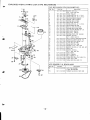
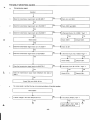
REMOVAL
●
AND INSTALLATION
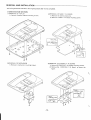
All wiring should be returned to the original position after work is completed.
1. BASE
STATION
(l) REMOVAL
SECTION
OF TOP LID
(2) REMOVAL
1) Remove 4 bottom cabinet mounting
screws.
OF MAIN P. W. BOARD
1) Remove the antenna lead wire.
2) Remove a MAIN P. W. Board mounting
screw.
1
(3) REMOVAL
OF MECHANISM
1) Remove 4 mechanism
mounting
I
(4) REMOVAL OF CONTROL P. W. BC)ARD
1) Remove 6 CONTROL P. W. Board mounting
screws.
2) Remove
the
CONTROL
figure.
&d!)
–13-
P. W. Board
screws.
as shown the
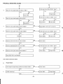
REMOVAL
AND INSTALLATION
(5) WIRING LAYOUT
● All wiring
should be returned to the original position after work is completed.
Ii
(1
r
!
111,1
1111
BASE
CONTROL
“
PW.B
\r
BASE
I
MAIN
PW, B
CoN’’”u
‘“%= ‘-”-r————.—_
I
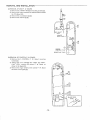
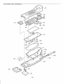
2. HANDSET
(I) REMOVAL
BASE
CONTROL
PWB
I
SECTION
n
(
LJ
OF CABINET
. The procedure for disassembly the handset is as follow :
1) Remove the battery compartment lid [0].
2) Remove the battery pack.
3) Remove a handle mounting screw [Q].
4) While pressing the shaded
area to release the
hooks on both sides of the cabinet [0], gently open
the bottom of the cabinet [0].
While gently
opening
the handle,
lift and remove
Jill
i
[0,
6].
I
y
I
/
PUSH
‘n
*
@
600
-14-
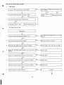
REMOVAL
AND INSTALLATION
(2) REMOVAL OF MAIN P. W. BOARD
1) Remove the 2 MAIN P.W. Board mounting
2) Remove the.solder
screws [0].
between the antenna lead wire and
the P.W. Board [Q].
3) Remove the 3 connectors
[@,@].
4) Remove the antenna [@,@].
(3) REMOVAL OF CONTROL P. W. BOARD
1) Remove the 5 CONTROL P. W. Board
mounting
screws [(D],
2) Taking
LOW”
care not to damage
LED’s,
remove
the “TALK”
the control
and “BATT.
P. W.
shown in the figure [Q].
3) Remove the ringer switch on the control
Board
as
P. W. Board
as shown in the figure [@]
-15–
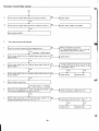
TAPE MECHANISM
ADJUSTMENT
PREPARATION
CLEANING
To ensure
charging
wiping
THE CONTACT
proper
charging
terminals
them
CASSEITE
with
POINTS
of the handset
on the handset
a soft cloth
Measuring
batfety
and the base
moistened
lightly
pack,
station
with
clean
once
isopropyl
(1)
the battery
a month
by
alcohol.
TAPES
After a message
tape has been in use for 6 months,
you should turn if over
and use the other side for the next 6 months. After that you should replace it
with another Sanyo cassette designed for answering-system
use. If you
decide to use another brand, make sure the tape is of high quality.
CLEANING THE HEADS
To ensure continued high performance from the answering system, clean the
head, pinch roller and capstan periodically, whenever dust or reddish-brown
oxide particles have accumulated. Failure to do so may result in inferior
sound qualify and inconsistent tape speed.
1. Open the cassette compartment lid.
2. Moisten a soft cloth or cotton swab with isopropyl alcohol, and gently rub
the surface of the heads, pinch roller and capstan until the dirt or oxide is
removed.
Test
FOR ADJUSTMENTS
instruments,
tools.
tape
OA-W41
:
OA-W411
MC-30 :
Head
:
azimuth
-1 OdB)
(3kHz,
Motor speed (3kHz, -lOdB)
Normal tape
(2) Oscilloscope
(3) AF-VTVM
(4) Frequency
counter
(5) Screwclriv”er (non-metallic)
for adjustments.
NOTE:
Remember that you own the unit. The telephone companv is not responsible
for its maintenance.
“r~
$.:;~:.:
*:,,
;::?<:;;:.:,:,.:..,.,.
:s...>....
......
:7%%
.+:.:.:..’:..%
,-.
. .................
.~\..+...
......
- ..:.:.}.,.,..,.,.:.,.,.,;.,
.............
o
t ‘:~.
>2
.0
:55
k’===+
:~L
9
___
*k
—
h
A
PARTS LOCATION
$] cN702
(+)
)
/4F
*
I
d
—
DC 9V
SPEED
vR80t
IZZ!l
MIN
Ei-1
7
+m
SPEAKER
–16–
OSCILLOSCOPE
,
2
VR703
v–l$s~~
,
(+)
(_)
CN902
MOTOR
VTVM
~’lzsiil
(+)
\,A,E,TAT,oN
25 ohm
+
TiiPE
MECHANISM
ADJUSTMENT
1. HEAD REPLACEMENT
AND AZIMUTH
ADJUSTMENT
RIP HEAD
(l)HEAD
Notes:
Siili5#-gi
REPLACEMENT
1) After
replacement,
demagnetize
the heads
by
2) Be sure to clean the heads before attempting
to
E. HEAD
using a degausser.
BLUE
make any adjustments.
3) All wiring should be returned to the original position after work is completed.
w
(2) HEAD AZIMUTH
ADJUSTMENT
1) Load the test tape (OA-W411,
etc. : 3kHz) for azimuth
adjustment.
2) Press the PLAY button.
HEAD AZIMUTH
ADJ.
3) Use a cross-tip screwdriver to turn the screw for azimuth adjustment so that the output is maximized.
of the adjustment,
use thread lock
4) After completion
(TB-1 401 B) to secure the azimuth adjustment screw.
2. MOTOR
REPLACEMENT
AND SPEED ADJUSTMENT
(2) MOTOR SPEED ADJUSTMENT
1) Insert the test tape (OA-W411,
(1) MOTOR REPLACEMENT
etc. : 3,000Hz).
2) Press the PLAY button.
3) Adjust VR801 so that the frequency
counter
reading
‘~
@@J
I
I
1
I
Q
o
‘> .I
Is
.<
3.000 Hz.
c
MOTOR SPEED
ADJUSTMENT
/
c .
c
e
G
1
,
–17–
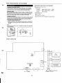
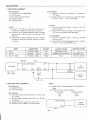
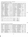
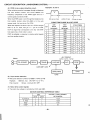
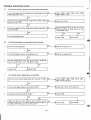
This cordless
telephone
is composed
base stations and the handset.
The 30 MHz and 39 MHz frequency
of
two
sections,
the
bands are used for these
communications.
There
are 10 channels,
each consisting
of two frequencies,
one from the 30 MHz band and one from the 3 9MHz band.
AT any given time, communications
between the base station
and handset use one pair of these frequency
channels.
CHANNEL
BASE STATION : TX
* HANDSET : RX
HANDSET : TX
* BASE STATION : RX
1
30.075 MHz
39.775 MHz
2
30.100 MHz
30.125 MHz
39.800 MHz
39.825 MHz
3
4
5
6
7
30.150 MHz
30.175 MHz
39.850 MHz
39.875 MHz
30.200 MHz
30.225 MHz
39.900 MHz
39.925 MHz
8
30.250 MHz
39.950 MHz
9
30.275 MHz
0(1o)
30.300 MHz
39.975 MHz
40.000 MHz
BASE STATION
TEL
--------:
I
o
CONTROL
TX
1
I
I
I
I
L
~1
I
L ----
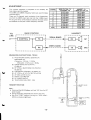
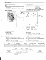
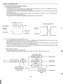
MEASURING
----
(1) FM STANDARD
Modulation
(2)
---
-110
J
I
I
+-El-a
L ----
----
----
M“
J
TOOLS
SIGNAL GENERATOR
MSG-2560B, etc.
(Frequency :100 kHz
i
RX
----
INSTRUCTIONS,
30 MHz BAND
1 ------I
I
I
39 MHz BAND
------
:
MHz
: 2,5kHz, Level : 46dBP)
LINEAR DETECTOR
(FOR FM ) :
LD-460 etc.
k
(3)
RF VTVM or ELECTRONIC
ML-69A etc.
(4)
FREQUENCY
COUNTER
VOLTMETER
: VP-4050A,
(5) AF VTVM or AF AC VOLTMETER
:
etc.
(ACVM)
(6) AF OSCILLATOR (1 kHz)
(7) DIGITAL VOLTMETER
(8)
DC POWER SUPPLY
(9) TELEPHONE
HANDSET
ANALYZER
:1050
SECTION
Note :
●
Disconnect
the Ni-Cd battery and feed 3.8V from the DC
power supply.
o During adjustment,
.
disconnect
the antenna lead wire.
Set unit to “TEST” mode by shorting
(POO1) as shown in right figure.
the “TEST
POINT”
TEST
POINT
● m-—
-
-REMOTE
PWB
44
POWER
SUPPLY
Oc 38V
SH;R T
a
-18–
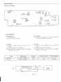
CONTROL
ADJUSTMENT
PARTS
LOCATIONS
}51
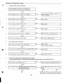
1. VCO
(HANDSET)
Unit Condition
(1) Press the “O”, fol!owed
Test Equipment
(1)
Digital voltmeter
(2)
DC Power supply (DC 3.8V)
(2)
Connect
P152.
by “X”
button on the hand-
set. And to set handset to channel
10.
2. Rx Vco
1. TX VCO
(1)
,,-..
a Digital
voltmeter
and
switch
S1OI
(1)
to
Connect
a Digital
voitmeter
and
switch
S101
to
P152.
(2)
Set switch S101 to the TX position.
(3) Adjust T253 (TX) so that the reading
voltmeter is 1.8 V ~0.2 V.
STEP
Set switch S101 to the RX position.
(3) Adjust TI 52 (RX) so that the rdading
voltmeter is 1.8 V ~ 0.2 V.
of the Digital
ADJUST
ADJUST
CONDITION
VALUE
of the Digital
SPECIFICATION
1.
TX VCO
S101
: TX SIDE
T253
1.8V
1.820.2V
2.
RX VCO
S101
: RX SIDE
T152
1.8V
1.8 & 0.2V
TX
R259(C265)TX
R157(C161)RX
Unit
Test
1
Slol
o
VCO
VCO
o
GND
1
–19–
Digital
Voltmeter
RX
Y
I
I
1
u
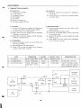
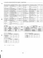
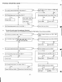
2. TRANSMITTING
(HANDSET)
Test Equipment
Unit Condition
(1) Change to channel
(1) RF Electronic Voltmeter
(2)
Linear Detector
Frequency Counter
(3)
(4) AF Oscillator
10 by pushing
“X” button
Connect IC651 pin i to ground
(2)
“O”, followed
by electrical
by
capaci-
tor (1OOflF 16.3V).
(5) AF VTVM
(6)
Dummy
(7)
DC Power supply (DC 3.8V)
Load (50 ohm)
\
1. TX POWER
(1) Connect a RF electronic
voltmeter
3. MIC MODULATION
(1) Connect a Linear detector
with 50 ohm pro-
(2)
Set switch S102 to the CARR position.
(3) Adjust T252 so that the reading of the RF electronic
voltmeter is maximum level.
(4) Adjust T251 so that the reading
voltmeter
is maximum
and switch S102 to ANT
test pin (CN151).
be, and switch S102 to the ANT test pin (CN151).
(2)
Set switch S102 to the MOD position.
(3)
Connect an AF oscillator
to microphone input.
(4) Adjust an AF oscillator
of the RF electronic
(Mod.: 1kHz) and AF-VTVM
so that the reading of the AF-
VTVM is 10 mV.
level.
(5) Adjust VR651 so that the reading of the linear detec2. TX FREQUENCY
tor is 1.5 kHz fO.1 kHz dev.
(1)
Connect a frequency
(2)
ANT test pin (CN151).
Set switch S102 to the FREQ position.
(3) Adjust
counter and switch S102 to the
CT451 so that the reading
of the frequency
counter is 49.770 MHz tO.5 kHz.
CONDITION
STEP
1. TX POWER
I 2.
3.
TX FREQUENCY
S102
: CARR
SIDE
I S102
: FREQ
SIDE
: MOD
SIDE
MIC MODULATION
S102
OSC
OUT
:10
ADJUST
ADJUST
T251
I
Maximum
“ T252
CT451
VALUE
I
VR651
40.000
SPECIFICATION
Level
MHz
1.5 kHz Dev.
I 40.000
1.5 tO.1
MHz
~0.5
kHz
kHz Dev. (1 kHz)
0.9 f 0.3 kHz Dev. (300 Hz)
2.7 t 1.OkHz Dev. (3 kHz)
mV
I
I
I
Frequency
~ FREQ
Unit
MIC +
Mod :1 kHz
Test
)
S102
o
Electronic
MOD
IC651
Pin 1
GND
Voltmeter
,
+
\\\’
AF
VTVM
RF
(DPX side)
– GND
CARR
L151
Oscillator
Counter
b
CN151
AF
I
Linear
Detector
100,uF I 6.3V
[
–20–
ADJUSTMENT
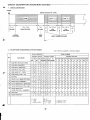
3. RECEIVING
(HANDSET)
Test Equipment
(1)
FM SSG (50 ohm,
Unit Condition
(1) Change
OPEN type)
(2) AC Voltmeter
(3)
(4)
DC Power Supply (DC 3.8V)
Distortion meter
(6)
Digital voltmeter
(2)
2.
a FM SSG
(1 kHz mod.,
Connect an AF-VTVM
and terminate
and distortion
a 150 ohm dummy
terminal.
(3) Adjust T351 so that the reading
is maximum level and minimum
RX RF
(1) Connect
2.0 kHz dev.,
“6”,
followed
by
capaci-
a FM SSG (46 dBP + O dBP) to the ANT
test pin (CN151).
30.100 MHz, 46dBP) to the ANT test pin (CN151).
(2)
6 by pushing
tor (10,uF / 16 V). ------ HCC : OFF Mode
1. RXIF
(1) Connect
to channel
%“ button.
Connect IC351 pin 16 to ground by electrical
(2)
meter in parallel
Adjust T151 so that the reading of the distortion
ter is minimum
distortion
me-
(less than IOYO).
load across the SP
3. RX AF LEVEL
(1) Connect a FM SSG (O dBP -46
of the AF voltmeter
distortion at distor-
dB~) to the ANT
test pin (CN151).
tion meter.
‘“
(2) Adjust VR352 so that the reading of the AF voltmeter
is 50 mV ~ 10 mV at SPEAKER output.
STEP
CONDITION
ADJUST
1.
RXIF
FM SSG
: 46dB/
T351
2.
RX RF
FM SSG
:
T151
3.
RX AF LEVEL
FM SSG
OdB~
: 46dBfl
CN151
ADJUST
I
VALUE
MAXIMUM
MINIMUM
VR352
I SPECIFICATION
LEVEL
DISTORTION
less than
50mV
50 mV
]
-----10%
flOmV
Unit
L151 (DPX SIDE)
Sp
7
+
FM SSG
GND
Mod. :1 kHz
Dev. :2.0
IC351
Pin 16
Test
)
Voltmeter
GND
+
kHz
Distortion
—
Meter
A
10,UFII6V
4. BATTERY
LOW (HANDSET)
Adjust
Test Equipment
(1)
(1)
Digital
Voltmeter
(2)
DC Power Supply
Adjust VR351 to obtain reading of OV at digital voltmeter.
(2)
Confirm at power supply as follows.
Voltmeter
Power supply
Unit Condition
(1) Disconnect
Ni-Cd battery feed 3.8V from power sup-
ply terminal.
(2)
Connect
digital
voltmeter
across
<0.5V
3.5V
>3.OV
IC351 pin 36 (Hot)
and ground.
(3)
(4)
reading
3.35V
I
I
I
I
IC351 Pin36
Change DC power supply from 3.8V + 3.4V.
Give a full turn to VR351 at counterclockwise.
Digital
I
I
GND
Unit
–21–
t
Voltmeter
ADJUSTMENT
*’
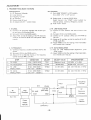
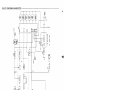
BASE STATION SECTION
TEST mode setting :
●
Before
NntI?
..
---- :
●
During adjustment,
disconnect
the antenna wire from the
base station unit.
.
Connect the AC Adaptor
connecting
DC 9V to uni, parform
operation.
Push 3 button at once :
“STOP” (SW454)
“PLAY”
(DC 9.0 V --- center minus) into
(SW453)
“ANSWER”
the DC jack.
the following
(SW452)
A beep signal will be heard after DC supply connected,
Or by shorting
PARTS LOCATIONS
“TEST”
round (solder side)
............
\,,
b’
....... .....
SHORT POINT
CN902
DC IN
m
VR703
~~ o~
S403
,
I
II
u
MIN
-., -
MAX
VOLUME
2
CN901
VR801
OFF LO H]
RINGER
TEL LINE
J
.>OFF ON ANS
CPC ONLY
1. VCO (BASE STATiON)
Unit Condition
(1) Setting band :10 channel (Initial setting)
Test Equipment
.*
(1)
Digital voltmeter
(2)
Frequency
Select channel 10 by
Frequency Counter.
Counter
2. RX VCO
(1) Connect a Frccluency
1. TX VCO
(1)
Connect a Frequency
(2)
Connect
102.
counter to CN101.
a Digital voltmeter
and switch
(2)
S103 to CN
RX VCO
at
counter to CN101.
a Digital voltmeter
and switch
S103 to CN
volt-
!meier is 2.5 V tO.2 V.
I
ADJUST
ADJUST
CONDITION
STEP
2.
Confirm
(3) Set switch S 103 to the RX posihon.
(4) Adjust T102 so that the reading of the Digital
meter is 2.5 V fO.2 V,
TX VCO
button.
102.
(3) Set switch S103 to the TX position.
(4) Adjust T202 so that the reading of (he Digital volt-
1.
Connect
“FFWD”
SPECIFICATION
VALUE
S103 : TX SIDE
T202
2.5 V
2.55 o.2v
S103 : RX SIDE
TI02
2.5 V
2.5 ? 0.2\J
Unit
Cb!lol
L1OI(H)
CNI02
IC403 Pin15
Pinl O
TX VCO
!=%
RX VCO
L
GND
(OPTIONAL)
-22–
’103
RX
1~
Digital
Voltmeter
ADJUSTMENT
2. TRANSMITTING
(BASE STATION)
Test Equipment
Unit
(1)
RF Electronic
(2)
Linear detector
Condition
(1) Set a S403 “RINGER” to OFF position.
Voltmeter
Set a S404 “CPC”
(3) Frequency Counter
(4) AF Oscillator
Dummy
(5)
(2)
Setting band :4 channel (30.225 MHz)
Load (50 ohm)
(6) AC Adaptor
Select
(DC 9V --- center minus)
voltmeter
4 by
“FFWD”
3. TX LINE MODULATION
(1) Connect a Linear detector
with 50 ohm pro-
button
and switch
pushed
fout
Counter
S104 to CN
101.
be, and switch S104 to the CNIO1.
(2)
channel
times at speedy. Confirm at Frequency
(3) Push “PLAY” button.
1. TX LEVEL
(1) Connect a RF electronic
to OFF position.
Set switch S104 to the CARR position.
(3) Adjust T201 so that the reading of the RF electronic
voltmeter is maximum at 50 ohm scale (about 4 dBm
(2)
Set switch S104 to the MOD position.
(3)
Connect an AF oscillator
TEL line.
(4) Adjust an AF oscillator
typical).
(1 kHz) and AF-VTVM
to
so that the reading of the AF-
VTVM is -20 dBm.
(5) Adjust VR603 so that the reading of the linear detector is 2.0 kHz fO.1 kHz dev.
4. TX DATA MODULATION
2. TX FREQUENCY
(1)
Connect a frequency
(1) After
counter and switch S104 to the
CT101 so that the reading
counter is 30.225 MHz iO.5
MODULATION
adjustment,
push
of the frequency
kHz.
t
I
I
LINE
button.
(2) Adjust VR602 so that the reading of the linear detector is 4.5 kHz tO.1 kHz dev.
(2) Set switch S104 to the FREQ position.
(3) Adjust
TX
“REW”
CN101.
STEP
1.
ADJUST
CONDITION
S104
TX LEVEL
: CARR
3.
TX FREQUENCY
TX
4.
TX
SIDE
S104 : MOD SIDE
LINE
MODULATION
I
: FREQ
OSC OUT
DATA
S104
MODULATION
Level
-4.0 dBm
t 1.5 dBm
1
[
I S104
SPECIFICATION
VALUE
Maximum
T201
SIDE
1
2.
ADJUST
30.225 MHz
CT101
\ 30.225 MHz t 0.5 kHz
to.1
kHz dev.
(1 kHz)
VR603
2.0 kHz Dev.
2.o
VR602
4.5 kHz Dev.
4.5 f 0.1 kHz dev. (1 kHz)
: -20dBm
: MOD SIDE
OSC OUT : -20dBm
CARR
L101(H)
AF
Oscillator
Loop
Simulator
TEL LINE
RF
(DPX side)
S104
o
Electronic
MOD
TEST
GND
T
Mod : lkHz
Voltmeter
Dummy
50 Otlln
Linear
Detector
(IEij
q.L)
=’-
–23-
.
1
3. RECEIVING
(BASE STATION)
Test Equipment
(1) FM SSG (50 ohm, OPEN type)
Unit Condition
(1)
(2) AF VTVM
(3)
(4)
Set a S403 “RINGER”
to LO / HI position.
Set a S404 “ANS.ONLY”
Distortion meter
Dummy Load (600 ohm)
(2)
to ANS. ONLY position.
(5) AC Adaptor (DC 9.OV --- center minus)
Setting band :6 channel (39.800 MHz)
Select channel 6 by “FFWD”
button
(6)
(7)
times at speedy. Confirm at Frequency Counter only
when changed a S403 “PULSE I TONE” to PULSE
Loop Simulator
Power Supply (DC 48V)
(3)
position .
Push “PLAY”
pushed
six
button.
I
(!
1. RXIF
(1)
2. RX RF
Connect
a FM SSG
(1 kHz mod.,
39.800 MHz,, 46dBp) to the CN101.
(2) Connect an AF-VTVM and distortion
and terminate
TEL line.
a 600 ohm
dummy
(3) Adjust T301 so that the reading
is maximum
1.5 kHz dev.,
load across
distortion
1.
RXIF
FM SSG
2.
RX RF
3.
RX AF LEVEL
FM SSG
CN101
1-
L1OI(H)
(DPX side)
~
Mod. :1 kHz
D12v.
:1.5
GND(E)
T301
10dBJ,
FM SSG : 46dB/
I
FM SSG
ADJUST
: 46dBP
:
distortion
me-
(less than 100/~).
the
at distor-
CONDITION
T101 so that the reacting of the distortion
ter is minimum
tion rmeter.
STEP
Connect a FM SSG (46dB,~ 4 10clB~) to the CN101.
Adjust
meter in parallel
of the AF volhmeter
level and minimum
(1)
(2)
T101
VR301
3. RX AF LEVEL
(1) Connect a FM SSG
(2)
(l OCIBP -+ 46dB~) to the CNIO1.
Adjust VR301 so that the reading of the AC voltmeter is -10 dBm t 1 dB at TEL line.
ADJUST
VALUE
Maximum
Level
at
Minimum
Distortion
Minimum
Distortion
-10 dBm
SPECIFICATION
-.--.-
less than
107.
-10 dBm f 1 dB (1 kHz)
-7.5 dBm f3 dB (300 Hz)
-19 dBm ~3 dB (3 kHz)
Unit
TEL LINE
LOOP
AF
SIMULATOR
VTVM
TEST
Dummy
600 ohm
GND
kHz
POWER
SUPPLY
DC 48V
Op
(OPTIONAL)
–24–
Distortion
Meter
EXPLODED
VIEW (HANDSET)
273
,-2-3-253
— Y202
I
255
I 6256
1./
&&
..-..,->,
,
‘. ...0
c.)
A
Y* ~
,1
/
@
207
Y202
205
Y202
257—
Y202
—Y201
0
–25–
EXPLODED
VIEW (BASE STATION)
—152
$_y102
\,,
&,
\
Q.
lo4—
,“
\
111
—Ylol
Ylol
—
8
154–
8 87
155–
~
y?
8
–Y101
A
K%%
0—114
.
9
&
Ylol
1-
%
—172
Ylol
</<1.
%
—108
/k!
&,.y&ylol
.
+
B
?%9?
11(
Ylo2———
,,
Y102 —(!$
–26–
’-
PARTS
LIST
PRODUCT SAFETY NOTICE
Each
precaution
in this
manual
should
be followed
during servicing.
Components
identified
with the IEC symbol
~ in the parts list
in which
safety
can be of special
significance.
When
replacing
a component
~, use only the replacement
parts designated,
or parts with the same ratings of resistance,
wattage
or voltage
that are
in the parts list in this manual.
Leakage-current
or resistance
measurements
must be made to determine
that exposed
acceptably
insulated
from the supply circuit before
returning
the product
to the customer.
and the schematic diagram designate components
identified
designated
parts are
CAUTION:
Regular
ACKIN
& ACCESSORIES
Ref.
No.
Part
614
614
614
614
614
614
614
614
614
614
614
614
614
614
614
614
261
h614
h645
h614
614
620
type
resistors
and
No.
216
241
176
176
250
250
243
237
265
265
265
272
272
272
265
272
222
006
256
245
197
capacitors
are
not
listed.
Ref.
Description
0954
6860
2395
3200
4284
4291
3522
1572
2305
4347
4194
6136
6228
6242
3661
6280
4922
4678
2949
8983
2597
SHEET,
SPEED DL
LABEL,CAUTION,
CRADLE
INNER
POLYE COVER,
REMOTE
INNER
POLYE COVER,
BASE
PAD, BACK
PAD,
FRONT
HANGER
LABEL,CAUTION
NOTICE
LABEL,CAUTION,
HANO SET
LABEL,
CRADLE
INNER
CARTON,
PRINT,COATING
INSTRUCTION
MANUAL
INSTRUCTION
SHEET
CARD,WARRANTY
LABEL,IDENTIFICATION,
BASE(NZ
SUPPLY)
BATTERY,RECHARGE
ADAPTOR,AC-DC
CORD
TAPE,CASSETTE
C-30,
TE CHCO
TAPE,CASSETTE,C-30,
OLYMPAS
:ABINE- &CHASSIS
Ref.
101
102
103
104
105
106
107
108
109
110
111
112
113
114
201
202
203
206
207
208
254
255
No.
Part
614
614
614
614
614
614
614
614
614
614
614
614
614
614
614
614
614
614
614
614
614
614
614
No.
250
255
241
250
250
250
235
235
239
272
250
235
129
051
247
233
241
272
242
256
268
248
265
To know those
Description
3881
8287
8284
3980
4017
4000
4452
4469
4304
5467
4093
8573
9082
9785
6673
3242
7850
5535
8313
2482
3125
6436
2350
614 265 2367
614 265 2374
614 268 3484
ASSY,LID,CASSETTE
ASSY,CRADLE,
SERVICE
TERMINAL,
CHARGE
BUTTON,
PAGE/INT
ANS/PLAY
BUTTON,
STOP/MEMO
BUTTON,
FF/REW
SHIELO,
FOR-OGM
SHIELD,
FOR-OGM
COVER,
VOL
ASSY,CABINET,BOTTOM
SPRING,PLATE,
TOP LID
MARKING
PLATE,
BOTTOM
LUG, ANT
LUG, CONT-MECHA
CABINET,
2ND DIE
CUSHION,RUBBER,
SP
KNOB,SLIDE
ASSY,HANDLE
ASSY,LID
BATTERY
BRACKET-E,
ROD.ANT
SWITCH,
DIAL
KEY
SWITCH,
LABEL,
KEY SUB
1/3
MAIN
(ACCESS
CODE1O)
LABEL,
1/3
MAIN (ACCESS
CODE20)
LABEL,
1/3 MAIN (ACCESS
COOE30)
LABEL,
1/3
CABINET,BOTTOM(AC1O)
.!
I
Part
refer
to
the
614
schematic
No.
268
diagram.
Description
614 268 3491
3507
LABEL,
1/3
CABINET,BOTTOM(AC20)
LABEL,
1/3
CABINET,BOTTOM(AC30)
‘IXING PARTS
Ref.
No.
‘IXING
Ref.
Part
411
411
411
411
411
411
Ylol
Y102
Y201
Y202
Y203
rY204
No.
Description
No.
021
021
023
022
023
022
3107
4005
1408
7807
3303
8408
SCR S-TPG
SCR S-TPG
SCR S-TPG
SCR S-TPG
SCR S-TPG
SCR S-TPG
ANTENNA
SPEAKER
ASSY,CONNECTOR-S,
MAIN-SP
2f
ASSY,CONNECTOR-S,
MAIN-MECHI
5P
ASSY,CONNECTOR-S,
MAIN-HEAD
3P
CORD
LUG, ANT
SPEAKER
PWB, REMOTE-SP
TERMINAL,SHEET
SWITCH,
DIALKEY
CORD, MAIN-CONT,FPC
CORD
ANTENNA,ROD,
ANT
ANTENNA,RUBBER,
ANT
CUSHION;
FOR BASE MIC
BIN 2.6X8
BIN 3X12
PAN
PAN
PAN
PAN
2,6X12,
HANDLI
2X6
2,6X8
2X8,
MAIN PCB
\RTS
Part
No.
Description
151
152
153
154
614
614
614
614
228
264
238
238
7118
9688
6095
6125
155
614
238
6118
156
209
251
253
256
614
614
614
614
614
236
129
252
265
267
6194
9648
0581
3487
0729
257
258
or
614
614
614
614
256
256
272
126
7401
2512
4422
6695
tEMOTE MAIN PWBASSY
CLICK
Ref.
271
CN151
or
or
CN651
CN652
CT451
D151
D251
D652
or
IC351
IC451
IC651
IC681
o r“
L451
Q151
Q152
–27–
.
No.
values,
!
No.
Part
No.
Description
614
614
614
614
614
645
614
407
265
017
251
251
241
004
007
157
3258
5721
0933
4283
0745
2881
6356
0202
407
407
407
409
409
409
409
409
645
405
405
157
003
008
322
346
238
142
039
001
045
015
0202
3609
5400
3506
3001
8305
2000
6629
4581
9108
9701
ASSY,PWB,
REMOTE MAIN
PLUG
PLUG
PLUG
SOCKET
PLUG,2P
TRIMMER
VARACTOR
DI HVU202-30
DI HVU202-30
VARACTOR
DIODE
DAN202K
DIODE MA151WK
IC LA8609M
IC MC145162D1
IC LA8630M
IC LA6358NM
IC NJM2904-T2
INDUCTOR,1OOU
TR 2SK543-4
TR 2SC2814-F4
K
<
PARTS
Ref.
No.
Q153
or
LIST
Part
405
405
405
405
405
405
405
405
405
405
405
405
405
405
405
405
405
614
645
614
645
645
645
614
645
645
645
614
614
614
614
614
614
614
:;51
Q252
Q253
Q254
or
;;51
or
;;51
::51
or
or
SP651
T151
T152
T251
T252
T253
T351
VR351
VR352
VR651
X451
XF151
XF351
or
or
or
XF352
No.
002
005
002
015
012
012
008
007
080
002
005
002
021
064
015
014
011
234
007
252
007
007
007
241
006
001
001
231
265
030
030
030
030
030
Description
0308
5508
6706
9701
9407
9407
7509
7708
2409
0308
5508
6706
2406
9202
6704
4509
1006
9618
0228
7481
0242
0235
0266
6754
2421
9319
9326
4326
3579
5074
5081
5098
5104
6675
Ref.
TR 2SA1037K-R
TR 2SA812-M6
TR 2SA1179-M6
TR 2SC2814-F4
TR 2SC2058S-P
TR 2SC2058S-P
TR 2SB815-B6
TR 2SB624-BV4
TR 2SB624-BV5
TR 2SA1037K-R
TR 2SA812-M6
TR 2SA1179-M6
TR 2SD1048-X7
TR 2SD1757K-S
TR 2SC2812-L6
TR 2SC2412K-R
TR 2SC1623-L6
BUZZER
TRANS,ANT,30MHZ
TRANS,OSC
TRANS,ANT,40MHZ
TRANS,ANT,40MHZ
TRANS,0SC,40MHZ
TRANS,IF
VR,SEMI,20K
N
VR,SEMI,1OK
N
VR,SEMI,1OOK
N
RESONATOR,XTAL
FILTER,LC
I.F
I,F
I.F
I.F
I.F
No.
273
CN653
CN654
CN655
D651
or
D951
L951
MC651
Part
614
614
614
614
407
407
407
645
614
No.
265
237
262
262
099
065
099
001
001
or
D017
or
D018
ICOO1
ICO03
:;01
or
or
QO02
or
or
QO06
or
QO07
or
or
QO08
or
or
QO1l
or
Q012
or
or
Q013
or
I or
FILTER
FILTER
FILTER
FILTER
FILTER
Q014
or
Q015
Q016
or
or
ASSY,PWB,
REMOTE MIC
ASSY,CONNECTOR-S
TERMINAL
TERMINAL
ZENER DIODE MTZJ1OB
ZENER DIODE GZS1OY
ZENER DIODE
MTZJ7.5A
INDUCTOR,1OOU
K
MIC
Sool
or
Xool
BASE OGMPWB
Ref.
REMOTE MICPWBASSY
Ref.
No.
274
L151
614
645
tEMOTl
Ref.
Part
No.
272
CNOO1
CNO02
or
DO02
DO03
DO05
or
DO06
DO07
DO08
No.
265
001
CONTROLPWB
Part
614
645
614
614
407
407
407
407
407
407
407
No.
265
007
254
260
117
117
003
008
126
126
126
ASSY,PWB,
REMOTE
INDUCTOR,2.2U
K
ANT
ASSY
I
Description
3241
1447
2682
2362
5001
5001
3609
5400
5702
5702
5702
No.
172
CN430
IC430
IC431
X430
Description
3272
5441
ASSY,PWB,
REMOTE
PLUG,2P
SOCKET
SOCKET
LED BR1102W
LED BR1102W
DIODE
DAN202K
DIODE MA151WK
LED PG1101W
LED PG1101W
LED PG1101W
405
405
405
405
405
405
405
405
405
405
405
405
405
405
405
405
614
614
614
or
Description
3265
1619
4654
4654
6102
1704
5808
4581
6314
407
407
407
407
407
407
407
407
410
409
409
405
405
405
405
405
405
405
405
405
405
405
405
405
405
DO1O
DO1l
D016
IEMOTE MICPWBASSY
Ref.
Part
No
DO09
Part
I
614
I
614
409
409
614
614
No.
Description
126
126
126
004
003
003
008
117
224
186
311
002
005
002
002
005
002
021
064
008
007
080
015
014
5702
5702
5702
0102
4507
3609
5400
5001
0906
4107
1902
0308
5508
6706
0308
5508
6706
2406
9202
7509
7708
2409
8704
4509
011
015
014
015
014
015
014
011
015
014
011
000
104
000
002
005
002
237
253
231
1006
8704
4509
8704
4509
8704
4509
1006
8704
4509
1006
0409
8806
3608
0308
5508
6706
1053
0955
4333
Ref.
173
CN451
D450
D451
D452
D453
D454
or
or
–28–
No.
Part
614
614
408
408
408
408
407
407
4.15MHZ
ASSY
No.
234
Description
I
82841
ASSY,PCB,BASE-OGM,
239 5448 PLUG
IC MSM6388GS-V1
260 8809
IC MSM6587JS,
BASE
304 9304
035 1613 CERAMIC
RESONATOR
219 02341 SHEET, FOR-OGM
BASE MCONTROLPWB
CONT
LED PG1101W
LED PG1101W
LED PG1101W
OIODE DCAO1O
DIODE
DAP202K
DIODE
DAN202K
DIODE MA151WK
LED BR1102W
IC LC66358B-4E99
IC RH5VA31CA
IC RH5VL31CA
TR 2SA1037K-R
TR 2SA812-M6
TR 2SA1179-M6
TR 2SA1037K-R
TR 2SA812-M6
TR 2SA1179-M6
TR 2SO1O48-X7
TR 2SD1757K-S
TR 2S6815-66
TR 2SB624-BV4
TR 2SB624-BV5
TR 2SC2812-L6
TR 2SC2412K-R
TR 2SC1623-L6
TR 2SC2812-L6
TR 2SC2412K-R
TR 2SC2812-L6
TR 2SC2412K-R
TR 2SC2812-L6
TR 2SC2412K-R
TR 2SC1623-L6
TR 2SC2812-L6
TR 2SC2412K-R
TR 2SC1623-L6
TR DTA114EK
TR FN1A4M
TR DTC114YK
TR 2SA1037K-R
TR 2SA812-M6
TR 2SA1179-M6
SWITCH
SWITCH,SLIDE
RESONATOR,XTAL
No.
250
239
016
015
015
015
037
037
BASE-OGM
OGM
I
ASSY
Description
3782
1570
8506
8903
8804
8903
3507
3408
407 037 3309
ASSY,PCB-W,
BASE
SOCKET,
CONT-MAIN
LED SLZ-135B-08-T1,
LED SLZ-135B-12-T1,
LED SLZ-135B-02-T1,
LED SLZ-135B-12-T1,
LED SLP-165B-51-C,
LED SLP-165B-51-B,
LED SLP-165B-51-A,
CONT
13P
CHARGE
IN USE
INT
ANSWER
POWER
POWER
POWER
PARTS
Ref.
LIST
Part
No.
D456
or
D457
or
D458
or
SW451
SW452
SW453
SW454
SW455
SW456
SW457
SW458
SW459
bf.
No.. . [
.- .. ..
Description
No.
DIODE
DIODE
DIODE
DIODE
407
SBO07-03CP
RB421D
SBO07-03CP
RB421D
407
407
407
407
407
066
146
066
146
066
7606
9001
7606
9001
7606
407
614
614
614
614
146
220
220
220
220
9001
5617
5631
5631
5631
OIOOE SBO07-03CP
DIODE RB421D
SWITCH,TACT, ERASE
SWITCH,TACT, ANSWER
SWITCH,TACT, PLAY
SWITCH,TACT, STOP
614
614
614
614
614
614
614
645
220
220
220
220
220
235
235
006
5631
5617
5631
5631
5631
4483
4476
4425
SWITCH,TACT,
MEMO REC
SWITCH,TACT,
OGM REC
SWITCH,TACT,
INT
SWITCH,TACT,
FF
SWITCH,TACT,
REW
SPACER,
FOR POWER LED
SPACER,
FOR LED L-ANGLE
FIXER
7272
4911
9752
2607
1704
4275
ASSY,PWB,
BASE-MIC
SOCKET,DIP
2P
SOCKET
ZENER DIODE
MTZ1OB
ZENER DIODE
GZS1OY
MICROPHONE
r
40B
r
’409
m
1412
,r
1413
Ii1414
br
1417
Ir
IASE tWCPVVBASSY
Ref.
Part
No.
Description
No.
CN704
or
D701
or
MICO1
614
614
614
407
407
614
ASE MAIN
PWBASSY
174
Ref.
No.
171
:402
:403
:422
:704
:901
Dr
:905
Part
614
403
403
403
403
~403
h403
403
263
035
237
053
065
245
Description
No.
272
135
196
038
200
2466
3609
4102
7407
8300
116 300B
283 1700
200
6900
:N101
614 225 6213
or
614
Dr
614 251 4276
CN102
or
or
CN401
CN701
CN702
or
CN703
CN801
CN901
CN902
:;101
D102
or
D201
D401
D,403
or
D404
or
D405
or
D406
or
614
614
614
614
645
614
614
645
645
~645
614
614
614
407
407
407
407
407
407
407
407
407
407
407
407
251
017
251
251
227
004
035
237
004
004
009
035
253
007
051
063
129
003
012
007
012
007
012
007
012
007
0926
5721
0933
4283
7935
2881
4911
9752
2898
2911
3838
9091
0931
6356
6805
8705
9103
4507
4406
9904
4406
9904
4406
9904
4406
9904
ASSY,PWB,
ELECT
ELECT
ELECT
ELECT
MT-POLYEST
MT-POLYEST
BASE-MAIN
2200U
M
1000U
M
220U M
1000U M
O.lU K
O.lU
1000U
ELECT
PLUG
PLUG
PLUG
PLUG
PLUG
PLUG
SOCKET,13P
PLUG,2P
SOCKET,DIP
2P
SOCKET
PLUG,3P
PLUG,5P
JACK MODULAR 2
SOCKET
JACK
TRIMMER
ZENER OIODE GZS5.lZ
ZENER DIODE MTZJ5.lC
DIODE
1SV136A02
DIODE DAP202K
DIODE
1SS133
DIODE
GMAO1
DIODE
1SS133
DIODE
GMAO1
DIODE
1SS133
DIODE GMAO1
OIODE
1SS133
DIODE
GMAO1
K
M
6.3V
6.3V
6.3V
10V
250V
250V
16V
1700
)r
1702
lr
)705
tr
)801
)901
}r
br
)r
)r
)r
)902
)r
)r
jr
~r
)r
)903
)904
>r
)905
1908
)r
)910
>r
)911
Dr
)912
or
D999
IC301
IC302
or
IC401
IC402
IC403
IC405
IC406
IC601
IC602
IC603
or
IC701
IC702
IC704
IC801
IC901
IC902
or
or
–29–
Description
Part
-.. No.
407
407
407
407
407
012
007
012
007
150
407 111
407 003
4406
9904
4406
9904
7703
3805
3609
407
407
407
407
407
407
407
407
407
407
407
407
407
407
5400
4406
9904
4406
9904
3609
5400
4406
9904
7606
9001
2607
1704
7501
L0407
~407
~407
L0407
A407
~407
~407
L0407
~407
~407
A407
h407
407
407
407
A407
407
407
407
407
407
407
407
407
~408
409
409
409
410
409
409
409
409
409
409
409
409
409
409
409
409
A407
~614
~407
~407
008
012
007
012
007
003
008
012
007
066
146
053
065
079
07B
078
078
070
070
070
078
078
078
070
070
070
053
070
063
003
012
007
012
007
012
007
053
051
022
343
142
039
224
243
346
120
138
065
248
142
039
199
201
205
084
1906
2002
2101
5605
5704
5603
1906
2002
2101
5605
5704
5803
5806
8101
9504
9304
4406
9904
4406
9904
4406
9904
3208
4306
7104
6708
2000
6629
1606
4200
3001
560 3
250 2
930 8
120 4
200 0
662 9
470 5
740 3
590 0
780 4
171 330 2
002 450 0
002 690 8
101 820 9
DIODE
DIODE
DIODE
DIODE
DIODE
OIODE
1SS133
GMAO1
1SS133
GMAO1
RB441Q
MA723
DIODE
DIODE
DIODE
DIODE
DIODE
OIODE
DIODE
DIODE
DIODE
DIODE
DIODE
D1ODE
ZENER
ZENER
DIODE
ZENER
ZENER
ZENER
DAN202K
MA151WK
1SS133
GMAO1
1SS133
GMAO1
DAN202K
MA151WK
1SS133
GMAO1
SBO07-03CP
RB421D
DIODE MTZ1OB
DIODE GZS1OY
SB02-03C
DIODE MTZ39A
DIODE MTZ39B
DIODE MTZ39C
ZENER DIODE GZS39X
ZENER DIODE GZS39Y
ZENER DIODE GZS39Z
ZENER DIODE MTZ39A
ZENER OIODE MTZ39B
ZENER DIODE MTZ39C
ZENER DIODE GZS39X
ZENER DIODE GZS39Y
ZENER DIODE GZS39Z
ZENER DIODE MTZ4.7B
ZENER DIODE GZS8.2Y
ZENER DIODE MTZJ8.2B
DIODE
DBB1OE
DIODE
1SS133
DIODE GMAO1
DIODE
1SS133
DIODE
GMAO1
DIODE
1SS133
DIODE GMAO1
ZENER DIODE MTZ12B
ZENER DIODE GZS12Y
VARISTOR
ERZTC4AK220
IC MC13135DW
IC LA6358NM
IC NJM2904-T2
IC LC66512B-4FO0
IC MN1380-R
IC MC145162D1
IC MC74HC373F
IC LC7366NM
IC MC14069UBF
IC LAB632M-R
IC LA6358NM
IC NJM2904-T2
IC MC14066BF
IC LA2605M
IC LC73B5M-R
IC LA5550M
PHOTO COUPLE PC724V
PHOTO COUPLER
PHOTO
PHOTO
COUPLE
COUPLE
TLP521-lGB
PS2501-1
’4
PARTS
LIST
&
Ref. No
IC903
or
or
IC904
or
or
L101
L102
L103
L801
L901
L902
L903
L904
NL901
Q101
Q201
Q202
Q301
&“
;:01
or
::02
Q403
Q701
;;02
;;03
;;04
or
or
Q705
or
Q707
Or
Q708
:;09
;;10
:;11
;;12
or
;;13
;;14
;;01
Q802
Q803
;;01
;;02
or
Q903
or
Q904
Q905
or
Part
A409
h409
h407
409
409
409
645
645
614
645
645
645
h614
~614
614
405
405
405
405
405
405
405
405
405
405
405
405
405
405
405
405
405
405
405
405
405
405
405
405
405
405
405
405
405
405
405
405
405
405
405
405
405
405
405
405
405
405
405
405
405
405
405
405
405
405
405
No.
040
204
121
027
267
281
001
001
249
004
001
004
027
027
002
035
012
012
015
014
002
005
002
000
000
015
014
015
014
015
014
002
005
002
015
014
021
064
015
014
015
014
015
014
015
014
002
005
002
015
014
015
014
008
008
015
014
015
014
015
014
015
014
018
015
014
Description
7404
4607
1204
1203
0509
6501
5441
4581
7715
0337
5519
0382
6992
6992
4821
8708
9407
9407
8704
4509
0308
5508
6706
0409
2908
8704
4509
8704
4509
8704
4509
0308
5508
6706
8704
4509
2406
9202
8704
4509
8704
4509
8704
4509
8704
4509
0308
5508
6706
8704
4509
8704
4509
2405
2405
8704
4509
8704
4509
8704
4509
8704
4509
0101
8704
4509
IC PC814
IC TLP520-GB
PHOTO COUPLE
IC L7806
IC NJM7806FA
IC RC7806FA
INDUCTOR,2.2U
INDUCTOR,1OOU
INDUCTOR
INDUCTOR,8.2U
INDUCTOR,47U
INDUCTOR,22U
Ref.
Q906
or
PS2505-1
:;07
;;09
K
K
:;10
Q911
or
or
R908
R909
R912
R913
R927
RY901
S403
K
K
K
CHOKE
CHOKE
VARISTOR
TR
2SK544-E
TR
2SC2058S-P
TR
2SC2058S-P
TR
2SC2812-L6
TR
2SC2412K-R
TR
TR
TR
TR
TR
TR
TR
TR
TR
TR
TR
TR
TR
TR
TR
TR
TR
TR
TR
TR
TR
TR
TR
TR
TR
TR
TR
TR
TR
TR
TR
TR
TR
TR
TR
TR
TR
TR
TR
TR
TR
TR
TR
TR
TR
TR
2SA1037K-R
2SA812-M6
2SA1179-M6
DTA114EK
0TC114EK
2SC2812-L6
2SC2412K-R
2SC2812-L6
2SC2412K-R
2SC2812-L6
2SC2412K-R
2SA1037K-R
2SA812-M6
2SA1179-M6
2SC2812-L6
2SC2412K-R
2SD1048-X7
2SD1757K-S
2SC2812-L6
2SC2412K-R
2SC2812-L6
2SC2412K-R
2SC2812-L6
2SC2412K-R
2SC2812-L6
2SC2412K-R
2SA1037K-R
2SA812-M6
2SA1179-M6
2SC2812-L6
2SC2412K-R
2SC2812-L6
2SC2412K-R
2SB698-F
2SB698-F
2SC2812-L6
2SC2412K-R
2SC2812-L6
2SC2412K-R
2SC2812-L6
2SC2412K-R
2SC2812-L6
2SC2412K-R
2SC3331-T
2SC2812-L6
2SC2412K-R
::04
or
S405
or
T101
T102
T201
T202
T301
or
T901
UR301
dR602
JR603
JR703
JR801
K101
(401
[701
[F101
AF301
or
or
or
XF302
–30–
No
Part
Description
No.
405
405
405
405
405
405
405
405
405
405
405
/&402
401
~401
402
008
007
080
015
014
015
014
024
008
007
080
046
022
016
048
~402
~614
614
614
614
614
614
614
614
614
614
614
614
614
614
645
645
645
614
645
614
614
614
614
614
614
614
614
614
048
252
234
259
234
259
234
259
252
252
252
252
030
252
252
006
006
006
232
006
231
231
253
265
030
030
030
030
261
750s
770.!
240$
8704
450s
8704
450~
5008
7509
7708
2409
9205
3008
4707
0002
4901
6750
8659
9792
8659
9792
8659
9792
7580
7504
7566
7511
3643
2721
4343
2421
2483
2421
4943
2414
4326
4333
6308
3586
5074
5081
5098
5104
3771
TR 2S8815-B6
TR 2SB624-BV4
TR 2S8624-BV5
TR 2SC2812-L6
TR 2SC2412K-R
TR 2SC2812-L6
TR 2SC2412K-R
TR 2SD612K-F
TR 2SB815-B6
TR 2SB624-BV4
TR 2SB624-BV5
RESISTOR
27 JCARBON
6.8K
JA
CARBON
22K JA
RESISTOR
47 JRESISTOR
47 JRELAY
SWITCH,SLIDE
SWITCH,SLIDE
SWITCH,SLIDE
SWITCH,SLIDE
SWITCH,SLIDE
SWITCH,SLIDE
TRANS,RF
TRANS,OSC
TRANS,RF
TRANS,OSC
I.F.T
I.F.T
TRANS
VR,SEMI,20K
N
UR,SEMI,500K
N
UR,SEMI,20K
N
JR,SLIDE
JR,SEMI,2K
N
?ESONATOR,XTAL
?ESONATOR,XTAL
4.15MHZ
?ESONATOR
CERAMIC
FILTER,LC
I.F
FILTER
I,F
FILTER
I.F
FILTER
I.F
FILTER
l/2W
l/41d
l/4W
lW
lW
‘..>
‘“h
–31–
EXPLODED
VIEW & PARTS LIST (TAPE
MECHANISM)
TAPE
MECHANISM
Ref. No.
B-9
7
8
&
10
‘4
.
B
‘Q
–13
I
—+
Part
(TM-CAS1200MEC/SP\
No.
1
412
044
6908
2
3
4
5
6
1
8
9
10
11
12
13
14
15
16
17
614
412
412
614
614
614
614
412
614
614
614
614
614
614
614
412
238
044
044
238
231
238
238
044
238
238
238
238
238
238
238
044
6293
7202
1200
6361
3286
6354
6248
7103
6378
9416
6347
9362
9393
9386
6330
7004
18
19
20
21
22
23
24
25
26
614
614
412
614
412
614
412
614
412
238
238
044
238
044
238
044
238
044
9379
6255
7400
6316
7301
6323
6700
,6279
6809
27
28
29
30
31
32
614
614
614
412
614
412
238
238
238
044
238
044
6262
9409
6286
7301
6309
7509
TAPE
SENSORP.
J
Description
WASHER,SPECIAL,
CUT 1.6X3.2X0.25T
PINCH
ROLLER
SCREW,SPECIAL,3P
1.7X12
SCREW,SPECIAL,3P
1.7X5.5
HEAD,RECORD/PLAYBACK
SPRING,COMP,AZIMUTH
SPRING,WIRE,PINCH
BASE,HEAD
SPACER
SCREW,SPECIAL,3P
1.7X6.5
HEAD,ERASE,DM-390
ASSY,SLIDE,HEAD
BASE
SPRING,WIRE,HEAD
BASE
ASSY,MOTOR,MM5B60T24-1-K
ASSY,REEL,SUPPLY
ASSY,REEL,TAKEUP
SPRING,PLATE,CST
HOLDER
WASHER,SPECIAL,
CUT 1,26X2.5X0.5T
ASSY,CHASSIS,MECHANISM
BASE
CUSHION,RUBBER,MOTOR
FIX
SCREW,SPECIAL,MOTOR
FIX
LEVER,REVIEW
ARM
SCREW,SPECIAL,ARM
SPRING,PLATE,FRICTION
i4ASHER,SPECIAL,2
.lX3.5X0.18T
GEAR,FWD
PJASHER,SPECIAL,
CUT 1.6X3.2X0.25T
;EAR,POWER
kSSY,FLYWHEEL
3ELT,SQUARE,V-15
SCREW,SPECIAL,PLAY
ARM FIX
LEVER,PLAY
ARM
SCREW,SPECIAL,PWB
FIX
W. BOAF?DASSY
@fi!ki)iijib
421
!crETs5
I)
29
d
407
–22
..
–32–
149
5307
SENSOR
NJL5161K,TAPE
END
IC BLOCK DESCRIPTION
ICOO1 LC66358B
No.
(Micro
Name
Signal
(PIN NAME & FUNCTION)
for
Processor
“..
Handset)
Active
Description of Function
1/0
No.
25
26
1’
Pll
Key Malnx Strobe Out
2
P12
Key Malrlx Strobe Out
o
o
Signal Name
Description
TALK LED
KEY MON
Talk LED Control
Key Monitor Signal Output
1/0
.Ovv
o
o
3
P13
Key Matrix Strobe Out
o
27
REMOTE
Rernole LED Control
o
4
P20
Key Matrix Strobe Out
o
28
PLL DATA
IC451
Channel Select
o
5
RX+
Not Used (Open)
o
29
PLL CLK
IC451 Channel Select
o
6
7
f32
II
] Non Connection
INC
RX POWER
RX Power Control
8
RX DATA
RX Data Input
9
TX MUTE
TX MUte Control
10
BUZZER
Buzzer Sound Control
11
TX POWER
12
HOLD
13
DIAL
14
RX MUTE
15
TEST
16
v~~
17
Osc
18
NC
Non Connection
19
NC
Non Connection
20
Osc
1
TX Power Control 1
Dial
LED
RX Mute Control
\ Not Used (Low)
PLL EN
IC451 Channel Select
o
33
TX DATA 2
TX Data -
0
o
34
TX DATA 1
TX Data +
o
35
BATT LOW
Battery Low Detect
_ow
I
I
36
CHARGE
Charge Detect
.Ow
I
LOW
o
37
TEST 1
Normal TEST mode
.Ow
I
LOW
o
38 ] TEST 2
I Self Check TEST mode
low
I
39
I Power Source ( + B)
o
System Clock Out
PLL
V“D
40
RING
41
US
42
NC
SW
/ AUS
System Reset Input
RX Volume Control
23
TX POWER 2
TX Power Control 2
24
BATLOW
BaNery Low LED Control
44
o
Ringer Swilch fnput
I
Model Scleclor
I
(Low)
Non Connection
Non Connection
1
Poo
Key Matrix Input
II
f
45
Po 1
Key Matrix fnput
I
o
46
P02
Key Matrix Input
I
LOW
o
47
P03
Key Matrix Input
LOW
o
48
Plo
Key Matrix Strobe Out
LOW
RESET
LED
LOCI<
143\NC
RX VOL
I
o
Matrix
P12
P13
P20
2
3
TALK
END
4
5
6
FLASH
SCAN
Pol
7
8
9
REDIAL
MEMORY
Poo
x
o
#
INT
REMOTE
Plo
Pll
P03
1
P02
IC401 LC66512B
(Micro
No. I Siqnal Name I
1
32
I
21
Key
I
o
I
22
1
o
_ow
LOW
System Clock in
2
Lock Change
31
Power Source (GND)
1
(Open)
o
LOW
Control
] Non Connection
30 I NC
LOW
Not Used (Pull Up)
LED
LED
Active
of Function
I P40
Processor
for
Base-Station)
Active
Description of Function
I I aich
Data/
-, —-—
KCV
Scan
I
Active
I I / O ] \ No. I Signal Name
I
I o
I DIS Control to IC702
,
I
II161D1S
!
Description
of Function
11/0
101
2
P41
Latch Data / Key Scan
o
17
INT CNT
I Intercolm Sinnal Switch
blGH
3
P42
Latch Da!a / Key Scan
o
18
LfN CNT
I TEL-Line
~IGH
o
4
I P43
Latch Data / Key Scan
o
~IGH
o
5
P50
Latch Data / Key Scan
o
6
P51
Latch Data / Key Scan
o
21
_ow
o
I Muting Control to IC702
II 19 I MUTE
20
D2
TX POWER
Signal Switch
o
D2 Control of fC702
2
TX Power Control 2
7
P52
Latch Data / Key Scan
o
22
TEST
Not Used (Low)
8
P53
Latch Data / Key Scan
o
23
v~s
Power Source (GND)
o
I
9
RE CODE O
Remote Code Select Switch
f
24
Oscl
System Clock fn
10
RE CODE 1
Remote Code Select Swi[ch
I
25
0SC2
System Clock Out
11
TX DATA 1
TX Data Output
o
26
RESET
System Reset Input
.ow
12
TX DATA
TX Data OuLput -
0
27
TX MUTE
TX Mute
.Ow
o
13
DO
DO Control to IC702
o
28
TX CNT
Mic Signal Switch
~fGH
o
DOS Control to fC702
o
29
RNG LVL
Ringer Level Control
IN USE LED
IN USE LED Control
.Ow
o
14
15
DOS
D1
2
+
D1 Control to IC702
o
30
–33-
o
I
o
IC BLOCK DESCRIPTION
(PIN
NAME
& FUNCTION)
&
No.
Signal
Name
31
INT LED
32
LATCH
3
Description
of Function
LOW
o
HIGH
o
..
A
I
LOW
CHARGE
LED Con[rol
LOW
ANSWER
LED Control
LOW
EARTH OUT
Earlh Out Conlrol
37
ST-SP
Slarf Control to IC430
38
PLL DATA
Channel Select to IC403
PLL CLK
Channel Select to IC403
PC2
Not Used (Low)
41
PLL EN
Channel Select to IC403
42
CHARGE
Charoe Detect of Handset
43
RING CP
Ringer / CPC Signal Input
FF
B
I 47
I Vox
48
POO
49
II
RX Mule Control
36
I
11/01 No.
La[ch (DTMF Generator)
E#!a
39
Active
INT LED Conlrol
Control
I 40
I
Description
Name
Key Scan / Da[a Input from
P02
Kuy Scan / Dala Input from
P03
52
Cw
Motor Control L to IC801
o
53
Ccw
Motor Con[rol R to IC801
o
54
RELAY
TEL-Line
55
E HEAD
Erase Head Control
56
v..
Power Source ( + B)
60
RX DATA
RX Data Input
61
REC I PLAY
REC / PLAY Con[rol to
Control
IGH
o
Low
o
LOW
I
1’1
I
Branch Check
LOW
I
I
IC430 (L : PLAY)
Busv InOut from IC430
LOW
I
Rotale Detect
LOW
I
62
RING O
Buzzer Sound oulput
VOX Signal tnput
LOW
I
63
TEST
Test
I
64
AC CHECK
AC Power Check
IC704
I
II
Key Scan / Data Input from
I
1’
o
block!
o
I
I
_ow
.Ow
Sw]tch
[ ] : Slide Switch
Poo
Pol
P41
I
ANS SET
OGM REC
PLAYBACK
PAGE / INT
P02
STOP
FFWD
P03
MEMO REC
REW
Key Matrix
P42
ERASE
1
ANS-ONLY
x
:
RINGER 1
LOW
x
HIGH
o
()
+
Short,
1]
[ANS-ONLY
2]
X +
,
–34–
1
[EARTH]
1]
[RING DELAY 2]
[RINGER 2]
[FLASH
2]
4 TIME
Open
P51
[FLASH
2 TIME
;
x
1
/ PULSEl
[RINGER 1]
x
RINGER 2
~ONE
[RING DELAY 1]
o
x
P50
[ANS-ONLY
AUTO
(RINGER)
OFF
P43
2
x
CPC ON
CPC OFF
I
Key Matrix
ANS-ONLY
Matrix
I
(ANSWER)
ANS ONLY
Note ;
I
IC704
o
(L : RING)
P40
I
Kev
I
IC704
Key Matrix
Mb
1/0
I
IC704
I
Active
of Function
101
I
Key Scan / Data Input from
Pol
50
51
o
o
o
o
o
o
HIGH
Signal
(RING DELAY)
RING DELAY 1
RING DELAY 2
x
x
o
;
x
IC BLOCK DESCRIPTION
IC430 MSM6388GS
No. ] Siqnal
1 \ CA1
2
] CA2
Name
(PIN NAME & FUNCT!ON)
(for OGfvl = Out-Going
Message)
Active
flo
No.
Cannel Select
I
29
I Cannel Select
I
Connect
f
Serial Rcglster.
!
DescrirMion
of Function
f
30
Signal
TAS
SAS
Name
Description
Serial
TAS
SAS
Serial Register.
naf for Senaf Address Wrl[ing
I
8
SAM 2
Sampllng Frequency Select
I
Connect
9
TEST
For LSI Test fLOW)
I
Serial
Register.
Head
Address
o
Write.
12 ] AOUT
13
I
14
FIN
AMON
I Non Conncc[mn
Internal 12 Blt DA Converter
I Analoq Voice Output
0
Connect
LOUT when Ret, or
Connect
DA Converter
InOut (FIN)
Csl
I
I Internal LPF Irmut
put when Playback.
15 I LOUT
32
33
CS2
LIN
I
Inverted
of Internal LPF,
Input
of
I Operational Amd[fier.
18
AVOO
I Power Source for Analog
19
SG
I Output
of Reference
I
Output
I for
Circuit
0
(Signal
of Reference
Anafog
for Read
I
/
I
Chip Select.
o
11
o
Chip Select.
34
CS3
I
Circuit
I
o
Chip Select.
I
35
CS4
36
XT
37
XT (Bar)
38
WE
39
40
af Register.
Vollagc
Ground). For fnternal
SGC
of
o
I
Internal
\ Power Source for Digi[al
20
Output
Connect CS Terminal of Seri-
DVOO
Analog
ofl
al Resister.
0
Amplifi-
17
for
Terminal
Connect CS Terminal of Seri-
er w!:h Input is LIN.
16
SAD
al Register.
Conneci
I Output of Operational
I
Address Data.
Connect CS Terminal of Scri-
o
Out-
Serial
1
Clock Termt-
Sampling Frequency Select
DAO
of
I
SAD
II
o
Terminal
SAM 1
I
of
Address Strobe.
7
11
o
Terminal
I
31
I/o
Transfer Address Strobe.
Connect
10 INC
Active
of Function
Connect Oscdlator
1
DVDO
Power Source for Diglial
I
DIN
Data Input.
f
0
Voltage
(Signal
Ground), For External
21
MOUT
1
22 I MIN
Output of Operational
I fnverted
Input
Operational
23
AGND
24
DGND
25 I RSEL 1
0
A.rnpllfl-
I er with fncmrtis MIN
of
Internal
I
Connect
Serial
Amplifier.
RSEL 2
Ground for Diaital
41
Ffeg-
f
Select Number of Serial Reg-
I
\ Select Number 0( Seral
ST-SP
DOUT
or End of Record
of
Termmal
of
I
DOUT
Data.
Or
During
HfGH
Pulse
RWCK
I
Standalone
/ Micro Processor
RWCK
Serial Register.
or Play-
Terminal
Playback,
Level hold.
Ty~e Select
I
Read / Write Clock.
Connect
Repeat Playback when HIGH
28 ‘ MCUM
Output
Data OutpUt.
Connect
42
Start of Record or Playback,
back.
Register.
o
of
Serial Register. Inpu[ of Read
ister
27
Terminal
W ntc Data.
Ground for Analog
iste r
26
DIN
I
43
2VCK
44
MON
I
for
I
Terminal
o
of
Clock Output
Data
Read
/
Write to Serial Resister.
I
Output 1 / 2 Frequency
Clock I
I
10
of Sampling Frequency.
L--
–35–
During
o
Record or Pfayback,
OLitmJt Low Level.
I
I
CIRCUIT
*
SYSTEM)
DESCRIPTION
1. OGM & ICM RECORD
START
MICRO-CASSETTE
TAPE
—
—
OGM
~
[
I
<
>
c
-
●
Max 16 sec.
3 sec.
BLANK
<
1
3 sec.
sec.
BLANK
OGM RECORD
●
6
1
Max 180 sec.
sec.
=++
1
sec.
ICM
RECORD
t
HO’M E
POSITION
—.
-
ICM
RECORD
t
I
I
I
●
Max 180 sec.
BEEP SOUND RECORD
Jiv
+
2. TELEPHONE
ANSWERING
SYSTEM
IC401
MODE
LC66512B
CONTROL
Jo.
TAS MODE
Note : See circuit diagram or schematic diagram.
IC702
OUTPUT
CONTROL
LA2805M
OUTPUT
CONTROL
SWITCHES
13 14 15 16 20 24 23 22
Sw Sw Sw Sw Sw Sw Sw Sw Sw Sw Sw
19
2
3
4
5
6
7
8
DO
D1
D2 DO D1 D2 MUTE 1
9 10 11
1
OGM REC (BASE-STATION)
L
-
H
H
L
L
H
L
L
o
0
1
0
0
0
0
0
0
1
0
2
OGM REC (HANDSET)
H
L
L
-
L
H
L
L
L
o
0
0
1
0
0
0
0
0
1
1
3
OGM PLAY (SPEAKER)
H
L
L
-
L
H
L
L
L
o
0
0
1
0
0
0
0
0
1
1
4
OGM PLAY (TEL LINE)
H
H
L
-
L
H
L
L
L
o
0
0
1
0
0
0
1
0
1
1
5
OGM SAVE (IC + TAPE)
H
H
L
-
H
H
L
H
L
o
0
0
1
1
0
1
1
1
1
1
6
OGM LOAD (TAPE - IC)
L
-
L
-
H
L
L
H
L
o
1
0
0
0
0
0
0
0
1
1
7
ICM REC
H
H
H
H
H
H
H
H
L
1
0
0
0
1
0
1
0
0
1
1
8
MEMO PLAY (BASE-STATION)
L
-
H
H
H
L
H
H
L
o
0
1
0
1
0
1
0
0
1
0
9
MEMO PLAY (HANDSET)
H
H
L
-
H
H
L
H
L
o
0
0
0
1
0
1
1
1
1
1
10
ICM & MEMO PLAY (SPEAKER)
L
-
L
-
H
L
L
H
L
o
1
0
0
0
0
0
0
0
1
1
11
ICM & MEMO PLAY (TEL LINE)
H
L
L
-
H
H
L
H
L
o
1
0
0
0
0
0
1
0
1
1
ICM & MEMO PLAY
L
-
L
-
H
L
L
H
L
o
1
0
0
0
0
0
0
0
1
1
12
(BASE-STATION ~ HANDSET)
13
BEEP REC
H
H
L
-
H
H
L
H
L
o
0
0
1
1
0
1
1
1
1
1
14
ROOM MONITOR
L
-
H
L
L
L
H
L
L
o
0
1
0
0
0
0
1
0
1
0
H : HIGH
L : LOW
-: LOW or HIGH
DO, D1
H : 3.5-4.2V
M:2 - 2.8V
L: O- O.8V
0: SWITCH
1 : SWITCH
“OFF”
“ON”
CIRCUIT
DESCRIPTION
1. THE BASE STATION’S DETECTOR
(1) The ringing tone detector circuit
The ringing tone detect
CIRCUIT
circuit detects
the ring signal when the ringing
forms the IC401 micro processor that the signal has arrived.
The ring signal coming in from the telephone line is transmitted
tone is sent from the telephone
from telephone
line and in-
line @ to @. At this time IC903 switch
to “ON” and “OFF”.
Then IC903 and Q909 control the level of pin 43 in IC401. IC401 reads the time between
“ L“ and “H” and thus deter-
mines that the ringing tone has been sent.
(The ringing tone is not detected
if the voltage is less than 20 Vrms when received.)
TEL LINE@ -@+@-.@
INSTANT
BREAK DOWN
48V
RING SIGNAL
I
TEL LINE
I
I
I
I
o-@
I
I
TEL LINE
@)to@
:+
PIN 43
IC401
~i
(2)
k~~;t
The CPC (Calling Parity Control) detection
This circuit detects the disconnect
CLA-1380AUS
,c401PIN43
● CPC
“OFF”.
detection
Detection
I
circuit
pulse (CPC), which is emitted
from the telephone
line is closed (i, e. off-hook),
line when a caller hangs up while
the direct current from the telephone
@ to @. Then , IC901 switches to “ON” and pin 43 in IC401 get into “L”.
current
in the
telephone
If, at the time, the caller hangs Up and the direct
to
r:
is in the AUTO answer mode, and inform pin 43 in IC401.
When the telephone
switches
~
Pin
43
line
is
line flows from telephone
disconnected
(through
CPC),
line
IC901
in IC401 then switches to “H”.
conditions
begins 2.5 sec. following
The CPC disconnect
off-hook.
pulse is detected
when pin 43 in IC401 is in the “H” level for 8 msec. or more.
IC902 . Q901 . Q902
BRANCH
RY901
@—
—
> IC401 PIN 44
DETECT
T901
LINE AMP
TEL SOCKET
Q701
@
/ Q702
IC901
*
IC401
PIN 43
RING DETECT
IC903 . Q909
SWITCHING ~lC401
Q907
–37–
PIN 54
CIRCUIT
a
DESCRIPTION
(3) The branch detection
The branch detection
circuit
circuit serves to detect the signal that is emitted when a telephone
that is branch-connected
goes
off-hook while CIA-1 380AUS is in the auto answer mode.
The circuit then informs IC401 and stops the auto answer mode.
When the telephone line enters the closed stated (i. e. off-hook),
through telephone
At this time, Q901. Q902 drive IC902, then switched
● Branch
detection
Detection
.
current
from the telephone
line flows
pin 44 in IC401 “L” and “H”.
condition
begins 2.5 sec. following
“L” is detected
the direct
line @ to @.
off-hook.
if pin 44 in IC401 if it continues
for 500 msec or more.
BRANCHES(OFF-HOOK)
TEL LINE
@to@
I
o
IC401 PIN 43
(4) The VOX (Voice activate recording)
II
detection
circuit
This circuit determines whether the signal sent from the telephone line while CIA-1 380AUS is in the auto answer mode
is voice, a busy signal, silence or a continuous sound, then stops auto answer mode.
While in the auto answer mode, the signal from the telephone
After being amplified
by the Amplifier
line is input to pin 3 in IC702.
inside IC702, the signal is output from pin 8 in IC702 and sent to pin 10 in IC702.
Then, the waveform shown in the figure below is output from pin 20 in IC702.
conditions
●VOX detection
The signal is interpreted sa a voice if “T” does not occur in 8 seconds in the following
15~T~8fJ
msec or 900 ~T~ 3r)orJmsec.
range:
VOICE
IC702 PIN 10
1
[
I
I
I
L
I
IC702 PIN 20
(IC401
T
PIN 47)
*
>
IC702
=“
T901
‘
‘
LINE
AMPLIFIER
>
Q701
&f
-38-
j—~
iC401 PIN 47 (VOX)
CIRCUIT
DESCRIPTION
(5) DTMF receive
When retrieving
line
from
frequency
signal
recorded
another
(ANSWERING
detection
circuit.
messages
through
location,
components
this
circuit
of the DTMF
control signal and informs
SYSTEM)
Example :0 and 3
a telephone
detects
signal
IC401.
When the DTMF signal is sent through the telephone
from
another
location
the
sent as a
while
CLA-I 600
is in the
line
0.5 sec or more
from
“L” to “H”.
DTMF TONE
the 4 bit signal that corresponds
to the key (16 DTMF
tone -pairs into a 4 bits code) is output.
IC401 is activated
in response
to remote
control
signals
sent from another location.
IN 4 BIT
CODE
LOW
HIGH
GROUP
FREQUENCY
FREQUENCY
12
13
12
11
1
697
1209
L
L
L
H
2
697
1336
L
L
H
L
3
697
1477
L
L
H
H
4
770
1209
L
H
L
L
5
770
1336
L
H
L
H
6
770
1477
L
H
H
L
L
H
H
H
L
L
KEY
pin 14 in IC704,
PHASE
GROUP
the level of pin 15 in IC704 changes
Then, from pin 11 -
0.5 sec or more
auto
answer mode, it is input to pin 2 in IC704.
When this happens,
within 2.0 sec
1C704 LC7385M
7
852
1209
8
852
1336
H
L
9
852
1477
H
L
L
H
o
941
1336
H
L
H
L
●
941
1209
H
L
H
H
#
941
1477
H
H
L
L
ALC CIRCUIT
CN901
Q710/Q711
g--tr=lw=ll
‘,NEAM,
LINE AMP.
/Q712
~~Rlc704’
#.
Q701
am
T
v
Q702
(6) Tape rotation
●
detection
Reel pulse detection
Playback
:
500msec.
End of rewind :
(7) Motor
●
drive
condition
max
10msec.
control
(at Q803-C / IC401 pin 46)
ON/ OFF (“L” or “H”).
minimum
ON / OFF.
signals
The motor drive voltage is controlled
by IC401 and IC801.
MOTOR
CONTROL
REFERENCE
VOLTAGE ( + ) AND (-)TERMINAL
IC401
52
pin
TABLE
OF THE MOTOR
53
pin
PLAYBACK
L
H
+ 2.5V
F. FWD
L
L
+ 5.OV
REW
H
L
-5.OV
STOP
H
H
Ov
–39–
“4
TROUBLE
A’
a.
1.
SHOOTING
GUIDE
The base station does not operate.
Is the AC adaptor connected
to an AC 240V line ?
Is the jack (DC 9V) connected
to the base station ?
Yes
+
2.
is the voltage
Pfo
of pin (1) of ic904 9V or higher ?
Is the voltage of AC adaptor output 9V ?
‘ Check AC adaptor.
Yes
+
No
3.
1s the voltage of pin (3) of IC904 6.OV ?
4.
Is the voltage of pin (56) of IC401 5.3V ?
No
+ Check D401.
1
W&
5.
Is the level of pin (26) of IC401 “High”
6.
Is the frequency
No
?
of pin (25) of IC401 “4.15MHz”
) Check IC402.
No
?
} Check the OSC. circuit include X401.
I
No
7.
Is the level of pin (64) of IC401 “HIGH”
b.
The handset does not operate.
1.
IS the voltage of pin (39) of icOOl 3.3v or higher ?
?
) Check D903, Q905 and Q401.
No
Check battery.
‘ Check connector
(CNOO1).
Yes
+
&
2.
Is the level of the reset terminal
of pin (21) of icOOl “high”
?
‘0
~
Check ICO03.
Yes
+
3.
Is the frequency
of pin (20) of IC401 4.15MHz
No
?
} Check XOO1 and ICOO1.
c.
The security code cannot be registered. (Base station)
(Voice communications are not possible by pushing the TALK button. The unit does not link.)
1.
Is the level of pin (42) of IC401 “Low” ?
No
~
Check charger terminals
Q903 and Q904.
Yes
4
2.
Is a modulation
signal (30MHz) being output to the antenna?
NO
Is TX data
‘ IC602.
being
output
to
pin
I
Check D201.
&
–40-
(15)
of
TROUBLE
SHOOTING
GUIDE
+
3.
Yes
4.
Is
RX data
being
input
to pin (60)
Is the level of pin collector
~ Q911 “High” ?
No
Is a carrier signal being output to the antenna ?
I Yes
I
of IC401
of Q906 and
No
+
Is the level of pin (57,
?
21)
of IC401
Yes
‘0
Check IC401.
-
“Low”
?
No
F==--ll-=
w
1
No
5.
IS RX data being output to pin (17) of IC301 ?
d.
The security code cannot be registered. (Handset)
(Voice communications are not possible by pushing the TALK button. The unit does not link.)
1.
Is the level of pin (36) of ICOO1 “High”
No
?
Check Q101 and IC301.
+ Check charger
terminals
and D951. QO07,
QO08.
Yes
&
IS a modulation
2.
signal
(4
Is TX
?
data
being
output
to pin (34) of ICOO1
‘ ‘?
Yes
Check D251.
+
,
3.
IS a carrier
signal
being
output
to the
antenna
H
?
Is there voltage in pin (C) of QO02 ?
I
I
IYes
Yes
No
Is the level of pin (11) of ICOO1 “Low”
Is RX data being input to pin (8) of ICOO1?
4.
Check ICOO1.
?
I
I No
Yes
1
I
Check ICOO1.
=
Check QO02.
Check ICOO1.
I
Is RX dada being output to pin (28) of IC351 ?
I
Is there voltage in pin (C) of Q253 ?
Yes
Check
‘1+
Q251,
and Q253.
-41 –
Q252
Check
CN651 .
No
CNO02
and
TROUBLE
SHOOTING
GUIDE
Transmission signal
e.
Handset
Does the transmission
1.
No
signal reach pin (B) Q651 ?
Check mic and D651.
Yes
+
2.
Does the transmission
No
signal reach pin (16) IC651 ?
) Check IC351 and Q651.
Yes
3.
Does the transmission
No
signal reach pin (13) IC651 ?
IS the level of pin (11) of IC651 “High”
?
1
Yes
Yes
No
4
.&
Base station
*&
Yes
+
4.
Does the transmission
No
signal reach pin (17) IC301 ?
b Check IC 301.
Yes
&
Does the transmission
5.
No
signal reach pin (6) IC602?
b Is the level of pin (16) of IC602 “High”
?
Yes
Check IC602.
+
,
6.
Check IC401.
Does the transmission
No
signal reach pin (9) IC701 ?
Is the level of pin (6) of IC701 “High”
Yes
Yes
No
+
L
,
Does the transmission
signal
reach telephone
line side of
T901 ?
=-
I No
Check T901 and Q702, Q713.
f.
No voice signal is emitted
during voice communications
of handset speaker.
Base station
+
1.
Is there voltage in the T901 telephone
No
line ?
) Is the switch (RY901 ) “ON” ?
,
Yes
Yes
4
Check CN901, R901, R908,
L903, L904 and C916.
+4iw
–42–
No
6
3
?
TROUBLE
SHOOTING
GUIDE
@
Is the level of pin (54) of IC401 “High”?
I
I
2.
Does the voice signal reach secondary
of T901 ?
I
Yes
Yes
No
I
I
Check T901.
I Is the level of collector
I
I
Does the voice
3.
signal
reach
of Q90i’ “Low”?
I
(E) of Q701 ?
pin
Yes
~Check Q701.
‘No
‘a
~
+
4.
Does the voice signal reach
No
pin (24)
of lC602
?
Check IC601, Q71O, Q711 and Q712.
)
Yes
5.
No
Does the voice signal reach pin (18) of IC602 ?
Is the level of pin (17) of IC602 “High”?
I
I
1
!
‘ies
No
Yes
+
HANDSET
ee
+
6.
Check IC351.
Does the voice level reach pin (18) of IC351 ?
1
Yes
+
7.
Is the level of pin (10) of IC651 “High”?
Does the voice level reach pin (3) of IC651 ?
YYes
‘0
+
8.
Does the voice signal reach terminal
‘~
speaker?
*
No
+
Check QO1O, QO11 and Speaker.
I
The number cannot be dialed.
9.
PULSE MODE
1.
Is the High/Low signal being emitted
No
to pin (54) of IC401 ?
Yes
2.
Is Q907 switching?
~’=-
Yes
–43–
check[c;l
TROUBLE
&
SHOOTING
GUIDE
h.
TONE MODE
1.
Does the TONE signal reach pin (20) of IC406?
2.
Does the TONE signal reach secondary
No
Is the signal : 3.58 MHz being emitted
(9) of IC406?
~
to pin
of T901 ?
Yes
No I
4
..
3.
Does the TONE signal reach Telephone
Line ?
I
[No
+
Check T901, L903 and L904.
I
i.
Check Q702 and Q713.
@
The ringer does not ring.
L
Base station
+
No
1.
Is not the position of ringer switch (S403) “OFF”
?
} Set ringer switch (S403) to the “HI” or “LO”
position.
Yes
2.
} Refer to the section (c) and (d).
Are the handset and base station linked ?
Yes
No
3.
Check CN901, L903, L904, D901 and D902.
Does the ringer signal reach pin (1) and (2) of IC903 ?
Yes
+
L>
4.
Is
the HI I LO
signal
being
emitted
IC903?
to pin (3) and (4) of ~‘0
Check IC903.
I Yes
+
No
5.
Is the Hi / LO signal being emitted to pin (12) of IC401 ?
I
I
I
1
I Yes
6.
Check IC401.
Does the ringer tone signal reach pin (62) and of IC401 ?
Yes
+
7.
Does the ringer tone signal reach pin (15) and of IC702?
No
) Check IC702.
1
I Yes
+
8.
Yes
Check speaker and speaker connector.
–44–
Handset
TROUBLE
SHOOTING
GUIDE
L
9.
No
Is the right tone signal being output to pin(l O) of ICOO1 ?
h
I
b Check ICOO1.
I
1
Yes
10,
Is the right tone signal being reached to collector
L
The intercom does not operate.
1.
Does the handset transmit with the telephone
Vec
.
No
line ?
(Handset + Base Station)
+
Is the voice signal
from the handset
(6) of IC702 ?
I
%1
-v
I
2.
of QO13 ?
being output
from pin
‘o
1
1
I
Check QO13, CN651 and CNO02
Refer to the station (e) and (f).
‘ (e : transmission signal), (f : No. voice signals emitte’s voice communication.)
1
I
) Check IC701.
I
1
Yes
4
3.
1s the voice signal from the handset
(8) of IC702 ?
being output
from pin
‘o
Are the voltage leaves of pin 22, 23 and 24
b in IC702 the same as those shown in the
“TAS MODE” table ?
I
4.
Is the voice signal from the handset
(15) of IC702 ?
being output
from pin
I
No
Check IC401.
Yes
5.
I
I Check CN701 and SP701.
I Yes
6.
Does the voice
microphone
being
signal
output
that
is
from
input
pin
(Base
from
Station+
Handset)
the
station’s
base
‘o
) Check microphone,
4 of lC701 ?
CN702 and D701.
#
7.
Is the voice signal that is input from the base station’s
crophone being output from pin 3in IC701 ? 1?
mi-
No
} Is the level of pin (5) of IC701 “High”
Yes
-45–
No
?
TROUBLE
SHOOTING
GUIDE
The OGM (outgoing message) recording does not operate.
Does the voice. signal that is input from the base station’s
microphone reach pin (5) of IC702 ?
1.
‘o
+
Check microphone,
CN702 and D701.
I
I
Yes
2.
Is
the voice
signal
being
output
from
+
3.
Does
the
voice
signal
reach
pin
pin
Are the voltage levels of pin (22, 23, 24) in
IC702 the same as those shown in the
(8) in IC702 ?
Yes
—
‘0
(22) of IC430 ?
&&
Yes
4.
I Is the
voic
e
signal
‘~
being output from pin (15)
of
IC430 ?
I
=%1=+--
*
j-2
1.
The OGM signal does not emanate from the speaker.
Is the OGM signal
being output from pin (12) of IC430 ?
No
) Check IC430 and IC431.
1
No
OGM
Does
3.
Is the OGM signal being output from pin (8) in IC702?
signal
reach
pin
No
Yes
Is the OGM signal
1
(6) of IC702 ?
2.
the
,
Are the voltage levels of pin (22, 23, 24) in
~ IC702 the same as those shown in the
“TAS MODE” table.
being output from pin (15) of IC702 ?
Check IC702.
Check speaker and CN701.
Check VR703 and IC702.
j-3
The OGM signal is not output to the telephone line.
1.
Is
2.
Does the OGM signal being output from pin (17) of IC702 ?
No
the
OGM signal
Check IC401.
being output from speaker ?
1
I Yes
No
Check Q702, T901, RY901, R902, R908, C916, L903, L904
and CN901.
–46–
b Check refer to the section (j-2).
%=7
* Are the voltage levels of pin (22, 23, 24) in
IC702 the same I as those shown in the
TROUBLE
SHOOTING
GUIDE
k-1
The ICM (incoming message) recording does not operate.
1.
Is the voice signal from the telephone
T901’s secondary side ?
line being output from
‘o
Check CN901, R902,
+ L904, RY901 and 1901.
R908,
C916,
L903,
.
2.
Does the voice signal from the telephone
from pin (3) of IC702 ?
1
line being output
No
Check Q701 ,Q703.
I Yes
+
3.
Is the voice signal from the telephone
pin 4 of IC702 ?
,
Check Record/play
line being output from
‘o
Are the voltage level of pin (22, 23, 24) in
+ IC702 the same as those shown in the
“TAS MODE” table.
head.
=
k-2
The ICM signal does not emanate from the speaker.
1.
is ICM recording
No
possible?
b Refer to the section (k-1).
I
2.
Is the OGM signal output to the telephone
No
line ?
Refer to the section (j-3).
k
3.
Are the voltage level of pin (22, 23 and 24) in IC702 the
same as those shown in the “TAS MODE” table.
&ti
I
The remote control signal does not emanate .
1.
Does the remote signal being output from collector
?
2.
of Q701
H
Check CN901, R902, R908,
L904, RY901 and T901.
1
No
Is the remote signal output from pin (3) of IC704 ?
C916,
L903,
I
Check Q701, Q71O, Q711 and Q712.
~
.
3.
Is the level of pin (15) of IC704 “High”
No
?
b Check IC704.
Yes
No
4.
When the signal is output from pin (15) in IC704, are the
voltage levels of pin (1 1) through (14) the same as those in
the table “DTMF tone pairs into a 4-bit code” ?
Yes
) Check IC702.
Check IC401.
‘w
–47–
TROUBLE
&
SHOOTING
GUIDE
m
The MEMO recording does not operate.
1.
Is
ICM recording
No
possible?
I Yes
Does the voice signal that
reach pin (5) of IC702 ?
2.
is input
from
the microphone
Check microphone,
Yes
T
Is
3.
put
the
voice
from
pin
signal
that
is
input
from
microphone
being
No
out-
(8) in IC702 ?
.
I
CN702 and D701.
F
1
.-
I
Refer to the section (k-1)
I
} Are the voltage
levels of pin (22, 23, 24) in
IC702 the same as those shown in the
“TAS MODE” table.
I
No
1
I
Check IC401.
*
The OGM recording is not possible with the handset.
1.
Is
memory
recording
possible
with
the
handset
Refer to the station. (m).
recording
(m : The memo
?
1
I
ate.)
Yes
does
not
oper-
(handset)
+
2.
Is the OGM recording
No
with the base station ?
Yes
*
3.
Are the voltage
as those shown
levels of pin (22, 23, 24) in IC702 the same
in the
“TAS MODE” table.
=+-I*
!.
!.
–48–
Refer to the station. (j-1). (j-2)
~ (j-1: The OGM recording does not operate.)
(j-2: The OGM signal does not emanate
from the speaker.) (handset)
VOLTAGES
OF [C & TRANSISTOR
Unit:
[o Handset
ICOOI
'' TALK''
Mode
atl
O-ch VDD:3.8V,
Base station
'' TALK''
and ``PLAY''
Mode
Volt
Y.
at10-ch]
LC66358B
Measuring
-------------
Pin No.
. -----
TALK MOOE
Measuring
--------
Pin No.
—— —--
. -----
TALK MOOE
Measuring
-------------
Pin No.
1
2
0
17
18
_____
0.3
0.3
33
.— —--
TALK MODE
-----
o
-----
3.7
34
3
4
_____
5
6
_____
7
____
11
_____
12
_____
13
_____
14
_____
15
_____
16
____
0
0
0
0
0
3.0
3.7
0
0
3.7
0
3.4
0
0
19
20
_____
21
_____
23
24
_____
25
_____
26
_____
27
_____
28
_____
29
_____
30
_____
31
_____
32
____
03
2.3
3.7
0
0
2.2
0.1
0
2.5
0
0
0.2
1.6
0
35
36
_____
37
38
_____
39
40
_____
3.7
0
3.7
3.7
3.8
6
7
-----
-----
-----
0
-----
-----
-----
22
----
----
8
_____
9
_____
43
_____
44
_____
45
____
46
_____
47
____
48
____
0
0
0
3.7
3.7
3.7
37
0
8
9
10
11
12
-----
013.7
41
10
_____
42
_____
ICO03 RH5VL31
Measuring
-------------
Pin No.
. -----
TALK MOOE
1
-----
2
3
____
3.8
3.8
0
1
2
3
4
5
13
14
15
16
TALK MODE
-------------
5.7
_____
5.0
_____
4.6
_____
5.8
_____
5.4
_____
5.7
_____
4.4
____
0
_____
4.9
_____
4.9
_____
4.9
_____
0.9
_____
5.8
_____
0.9
,____
09
----
33
____
PLAY MODE
5.7
5.0
4.6
5.8
5.4
5.7
4.4
0
4.9
4,9
4.9
0.6
5.8
0.6
0.6
2.2
21
22
23
24
12
13
_____
15
16
____
IC301
MC13135
Measuring
Measuring
IC302
Pin No.
Pin NO
17
18
19
20
TALK MO LIE
2.8
5.8
5.8
4.8
5.8
5.8
0
0
PLAY MODE
2.6
5.8
5.8
4.8
5.8
5.8
0
0
LA6358NM
Measuring
Pin No.
TALK MODE
-------------
1
-----
PLAY MODE
IC351
Pin No.
. -----
TALK MODE
Measuring
-------
2
6
7
8
2.0
.----,
0
2.9
_____
2.9
-----
2.9
_____
5.8
2.0
3.3
2.0
0
2.9
2.9
2.9
Pin No.
—-----
Measuring
-------------
1
-----
1.28
17
. .___—
TALK MOOE
Pm No.
-----
2
3.7
-----
18
-----
-----
3
-----
2.8
----.
19
1.0
1.2
33
34
---—-
35
-----
2.1
2.1
1
2
1.1
TALK MOOE
5
----
5.8
4
-----
0
-----
20
5
1.23
-----
1.2
-----
6
1.28
21
22
_____
0
3.4
7
----
-----
8
9
_____
10
-----
3.0
3.3
23
24
_____
25
_____
26
-----
1.2
3.5
0
1.3
----
41
42
-----
1.23
3.8
3.7
27
_____
28
_____
29
_____
3.0
3.0
37
—— ---
38
-----
2.1
3.7
3.2
3.7
3.7
3.7
3.0
2.9
1.3
1.3
3
4
5
6
7
8
9
10
11
12
-----
39
-----
-----
----
-----
43
----
-----
14
-----
1,7
0
0.7
30
31
_____
2.0
2.1
2.1
1.2
13
14
15
16
-----
----
32
44
36
-----
40
11
.----
1.23
2.98
LC66512B
Measuring
Pin No.
TALK MODE
-------------
-----
PLAY MODE
Measuring
--------
4
3.4
-— ---
LA8609M
Measuring
-------------
IC401
3
3.0
Pin No.
TALK MOOE
—— ---
. -----
PLAY MODE
Measuring
Pin No.
TALK MOOE
------------
-. -----
PLAY MODE
Measuring
PLAY MODE
0
0
0
____
5.3
5.3
5.3
0
0
0
0
0
5.3
0
0
0
0
17
18
19
20
21
22
23
24
25
26
27
28
29
30
31
32
0
5.2
-----
0
0
_____
0
____
2.5
_____
2.6
_____
5.2
-----
5.5
0
_____
5.3
-----
0
.___—
o
-----
-----
0
.— ___
-----
-----
-----
0
-----
0
-----
0
-----
-----
0
-----
-----
0
-----
0
-----
-----
0
0
5.3
---_-
0
-----
5.3
5.3
5.3
0
-----
4.5
----
----
0
o
5.2
0
5.2
5.8
0
0
2.5
2.6
5.2
5.6
0
5.2
0
4.4
0
33
34
35
36
37
38
39
40
41
42
43
44
45
46
47
48
4.5
4.5
-----
0
0
_____
5.2
----
0
_____
0
5.0
-----
4.8
5.2
-----
4.7
5.2
F/ish
4.9
5.2
62
63
64
5.0
----4.4
o
Pin No.
TALK MODE
-------------
o
o
-----
.----
5.3
-----
0
0
0
0
0
5.0
5.2
52
53
54
55
56
57
58
59
60
61
1.4
1.7
0
4.5
5.3
----.
2.2
5.3
50
51
5.2
5.2
-----
5.2
5.2
-----
-----
0
49
5.2
0
4.4
5.2
. -----
-----
-----
0
-----
1.8
2.6
_____
0
5.6
---5.6
–49-
-----
5.3
5.3
-----
0
5.3
-----
5.6
5.3
.----
0
-----
-----
.----
0
0
0
-----
-----
0
5.0
5.0
----
----
5.3
5.6
5.2
a
VOLTAGES
IC402
OF IC & TRANSISTOR
unit
MN1380R
:
vo/t
EE!EEEl
1(2403
MC145162
Measuring
-------
Pin No.
TALK MODE
—-----
1
2
3
4
o
_____
0
_____
0
_____
0
_____
2.3
____
0
____
o
0
0
0
2.3
0
5
6
PLAY MODE
[C405
5
6
7
8
9
10
11
12
13
14
15
2.4
____
2.4
____
2.4
____
2.5
____
0
____
4.9
___
0
____
2.4
____
2.5
----
2.4
2.4
2.4
1.25
0
4.9
0
2.4
5.0
4.1
7
8
9
10
11
12
13
14
15
16
16
----
0
LC74HC373M
Measuring
1
2
3
4
TALK MODE
-------------
o
. _____
0
_____
0
_____
0
_____
PLAY MODE
o
0
0
0
17
18
19
20
o
6.0
____
6.0
. _____
6.0
___
o
6.0
6.0
6.0
1
2
3
Measuring
Pin No.
Pin No.
TALK MOOE
—-------—
----
-----
PLAY MODE
IC406
0
5.3
____
0
0
____
0
____
0
5.3
____
5.3
----
0
0
____
0
0
5.2
0
0
0
0
5.2
5.2
0
0
4
5
6
7
8
9
10
11
12
13
14
15
16
0
____
0
____
----
____
---
-----
0
----
0
LC7366NM
MeasuringPin No.
TALK MOOE
-------------
6.0
6.0
0
_____
0
_____
0
_____
0
_____
0
0
___
0
0
___
6.0
6.0
0
0
0
0
0
0
0
6.0
0
17
18
19
20
TALK MOOE
o
0
0
0
PLAY MOOE
o
0
0
0
1
2
3
4
5
6
7
8
9
10
0
_____
5.5
_____
0
____
0
_____
0
_____
0
_____
-----
PLAY MOOE
Measuring
IC430
0
____
Pin No,
-----
----
0
----
----
6.0
0
0
____
0
0
0
0
0
11
12
13
14
15
16
0
____
0
___
0
0
____
3.5
____
7.3
____
----
----
MSM6388GS
Measurtng
Pin No.
TALK MOOE
-------------
5.5
5.5
_____
0
5.7
_____
5.5
5.5
0
5.7
0
5.5
0
0
0
0
0
0
0
0
0
17
18
19
20
21
22
23
24
25
26
27
28
29
30
31
32
TALK MOOE
5.5
5.5
0
0
2.5
3.4
0
0
0
0
0
0
55
5.5
5.5
5.5
PLAY MOOE
5.5
5.5
0
0
3.4
3.4
0
0
0
0
0
0
5.5
5.5
5.5
5.5
41
42
-----
PLAY MODE
Measuring
Measuring
Pin No.
Pin No,
-----
----
0
33
34
35
36
37
38
39
40
43
44
TALK MOOE
-------------
5.5
_____
5.5
_____
5.5
_____
0
_____
0
_____
5.5
_____
5.5
____
5.5
____
0
____
5.5
____
0
____
5.5
____
PLAY MOOE
5.5
5.5
5.5
0
0
5.5
5.5
5.5
0
5.5
0
5.5
1
2
3
4
5
6
7
8
9
10
11
12
13
14
15
16
0
5.5
____
5.5
___
5.5
____
0
____
55
____
5.5
____
IC431
MSM6587JS
Measuring
Pin No
TALK MODE
------------—
PLAY MODE
Measuring
--
Pi” No.
TALK MOOE
—- —- —— ----PLAY MOOE
IC451
. -----
5.5
5.5
5.5
-----
5.5
_____
0
_____
5.5
_____
5.5
____
5.5
_____
5.5
____
5.5
5.5
5.5
5.5
0
5.5
5.5
5.5
5.5
0
5.5
5.5
5.5
0
5.5
5.5
17
18
o
_____
-----
____
----
0
o
0
1
2
3
4
5
6
7
8
9
10
11
12
13
14
15
16
o
0
0
0
1.4
0
1.4
1.4
1.4
1.8
0
3.0
0
18
1.8
0
MC145162
Measuring
Pln No
TALK MODE
–50–
VOLTAGES
IC601
OF IC & TRANSISTOR
Unit:
MC14069UBF
Measuring
Pin No,
1
TALK MODE
-------------
o
_____
PLAY MODE
5.2
IC602
TALK MODE
—________
Measuring
9
10
11
12
13
14
4.9
---
0
____
0
5.2
49
-----
0
4.9
____
2.5
0
2.2
2.5
2.5
2,5
2.5
2.5
4.5
2.3
2.5
----
8
----
-----
,----
3
4
5
6
7
8
9
10
11
12
13
14
15
16
2.9
____
0.6
____
2.9
____
2.9
____
2.9
____
5.6
____
0
5.0
-----
0
2.9
_____
5.6
_____
2.9
2.9
_____
5.0
____
2.9
2.8
2.9
0.8
2.9
2.9
2.9
5.6
0
2.1
0
2.9
5.6
2.9
2.1
2.1
17
18
19
20
21
22
23
24
2.9
3.1
____
0.6
2.9
____
2.9
----
2.9
___
2.9
2.9
0.6
2.9
2.9
2.9
9
10
____
11
____
12
----
14
15
_____
16
____
3.4
3.7
1.7
7.7
77
0.6
7.7
10
11
12
13
14
15
16
-----
5.6
-----
5.6
3.1
,----
2.9
----
____
-----
-----
LA6358NM
TALK MODE
_________
1
2
3
4
5
6
7
8
2.9
_____
2.9
_____
2.8
0
____
2.9
____
2.9
____
2.9
____
5.7
___
2.9
2.9
2.8
0
2.9
2.9
2.9
5.7
4
____
5
____
PLAYMOOE
,----
LA8630M
Measuring Pin No.
_-———
________
1
_____
2
_____
1.7
TALK MOOE
0.6
3
____
1.7
1.7
7.7
6
____
1.7
7
____
8
____
0
7.7
____
3.4
-----
13
-----
LA6358NM
Measuring Pln No.
-_——
_________
1
_____
TALK MODE
lc701
2
_____
7.7
1.7
3
____
4
____
7.7
0
5
____
1.7
6
____
1.7
7
____
8
___
17
3.4
LC4066BM
Measuring
Pin No.
TALK MODE
-------—
----PLAY MODE
IC702
-----
1
2
4
5
6
7
2.9
0
_____
2.8
_____
0
_____
0
____
4.9
____
0
____
2.9
___
2.9
____
0
0
____
0
-—_—
2.9
2.9
2.3
0
0
0
0
2.9
2.*O
2.3
0
0
4.7
5.8
1
2
3
4
5
6
7
8
9
10
11
12
13
14
3
8
9
2.8
____
---
----
5.8
LA2805M
Mcasurlng
Pln No.
TALK MODE
—_ —______
----
0
0
____
0
____
0.6
____
5.0
____
3.5
0
0
0
0
0
0.6
5.0
17
18
19
20
21
22
23
24
TALK MODE
------
3.7
_____
3.4
_____
2.6
,____
0
_____
0
0.1
____
0
____
0
___
PLAY MODE
3.7
3.4
0
5.0
0
3.7
0
0
1
2
3
4
5
6
7
8
PLAYMODE
Measuring
------—
IC704
Pln No
3.5
. _____
____
0
____
____
0.2
____
3.7
3.7
____
9.0
___
3.4
—---
0
3.7
3.7
8.2
3.4
0
3.4
9.5
9
10
11
12
13
14
15
16
____
0
----
. -----
0
-----
3.4
----
10.3
LC7385M
Measuring
---
--------
Pin No.
TALK MODE
— _________
3.0
. _____
3.0
3.0
____
3.0
,____
0
____
2.7
____
2.8
____
0
0
____
5.2
____
5.2
___
5.2
-----
PLAY MODE
3.0
3.0
3.0
3.0
0
0
2.7
2.7
0
0
5.2
5.2
5.2
5.2
0
0
17
18
o
_____
6.0
____
o
6.0
1
2
3
4
5
6
7
8
9
10
11
12
13
14
15
16
o
_____
0
_____
0
_____
0
_____
0
_____
1.7
____
0
____
52
____
52
____
0
____
0
___
o
____
5.7
____
5.7
----
0
-— --
0
1.7
0
4.8
5.0
0
0
0
5.6
56
5.0
Measuring
Pin No.
TALK MOOE
—---PLAY MODE
IC801
-----
0
____
____
-----
5.2
-----
0
----
0
LA5550M
Measuring
--
7
0
____
2
Meawring Pin No.
lc681
6
2.8
2.8
_____
PLAY MODE
IC651
2.5
5
2.8
____
2.9
. _____
Pin No,
TALK MODE
-------------
--——
0
2. c1
____
1
PLAYMODE
IC603
4
3
2.8
,____
LA8632
MeasuringPin No.
----
2
4.9
_____
Volt
P,,? No.
TALK MODE
—— —________
PLAYMODE
0
0
5.5
0
17
18
19
20
TALK MODE
_____________
o
_____
0
_____
PLAY MOOE
0.4
Measurrng
Pln No.
1.2
0
_____
0
____
1.4
____
0
q
0
3.0
–51–
VOLTAGES
IC901
OF IC & TRANSISTOR
PC724V
Measuring
IC902
Pin No.
TALK MODE
-------------
1
. -----
PLAY MODE
IC903
o
2
0
-----
o
-—
0
0
—-.
-----
-----
0
~
---:
~-
~
IC904
Pin No.
1
2
4
3
L7806
Measuring
Pin No.
1
I
TALK MODE
-------------
--
PLAY MODE
o
—_-
-----
o
0
Volt
3
PC814
Measuring
Unit:
TLP521
-----
0
0
----
0
2
I
3
I
I
6.0
PLAY MODE
6.4
9.9
0
6.0
1
TRANSISTOR
Transistor
Measuring
---------.-.-—----
No.
Qool
Pin Name
Transistor
Measuring
-----------------—
Measuring
---------————
c
El
_____
3.7
No.
-----
3.1
E
E
.—_—-
c
-___—
No.
B
_____
-----
1.1
E
-----
2.7
Pin Name
-----
-----
E
-----
c
No.
-----
B
-----
0
E
-----
3.8
-----
TALK MODE
E
-----
3.8
c
c
-----
B
-----
c
_____
E
-----
B
———-.
-----
3.1
E
-----
0
E
_____
c
_____
B
_____
E
_____
c
_____
B
____
0
0
0
0
0
0
0.6
Q013
B
_____
0.2
E
-----
c
_____
0
0
c
B
E
_____
3.1
0.3
-----
c
-----
B
-----
B
_____
c
_____
5.4
E
-----
2.3
0.6
B
_____
Transistor
No.
s
_____
o
_____
3.66
0
-----
TALK MOOE
Transistor
Measuring
------------------
-----
-------—---—
------
—--------
No.
E
3.1
I
E
-----
3.8
-----
B
4.9
--——-
-----
E
-----
3.8
B
_——_-
c
E
.—__—
2.5
-----
0
-----
TALK MODE
-----
c
_____
1.3
0
c
B
____
3.7
B
____
2.4
0.6
Q252
B
_____
3.2
-----
.-—--
0.7
E
6.7
6.2
---------
c
-----
B
2.8
5.3
0
7.5
3.6
-----
-----
3.3
E
1.9
-----
1.7
I
I
-----
a
,
---------
-----
0
6.7
-----
0
6.2
---------
E
1.0
0.9
---------
0
E
c
--—--
0
----
3.5
B
0.4
-----
B
_____
-----
c
-—_--
-----
0
2.8
-___—
0
-——-.
0
2.8
0
6.8
2.5
-----
-----
6.3
2.3
E
0
c
2.4
2.2
–52–
-----
0
I
t
-----
,
1
B
E
----.—---
0
---------
1.6
1.5
---------
E
B
_____
E
.___—
3.1
0
_____
-----
2.8
0
0.5
0.4
---------
c
3.3
3.0
B
3.0
-----
c
0
-——--
Q651
-----
B
0.6
_-——-
-----
E
0.1
.—---
-----
6.0
-----
6.0
I
,
-----
1
#
c
-----
B
6.0
_____
0
6.0
E
.——_—
.----
0
I
1
-----
1.1
_____
1.0
-----
E
5.7
.__-—
5.6
---------
c
c
--——-----
0
1
1
0801
B
J
----
B
0.7
—---
Q705
0
Q71O
c
22
--—-—
Q704
Q714
B
—---
2.98
3.7
c
Q709
c
I
Q451
E
Q713
B
E
-----
Q703
c
Q708
B
——---
0
Q702
6.9
c
c
-_——-
Q351
Q403
5.3
47
I
Q301
E
._-——
3.1
5.3
_____
-----
Q707
B
-__—-
2.8
-—---
B
_____
c
____
c
5.3
.——--
Q712
Pln Name
PLAY MODE
-----
I
Q402
5.3
1
No.
------------------
c
5.5
-———-
2.8
I
Measuring
------------------
B
2.2
C?254
Q701
I
Transistor
-----
No.
Pin Name
Transistor
-----
3.7
5.3
PLAY MOOE
I
E
5.3
.—---
PLAY MODE
TALK MOOE
c
I
Q401
------------------
Measuring
--------------_—-—
-----
No
TALK MODE
Trans!slor
E
1.8
Pin Name
E
_____
G
_____
0.26
Q251
5.5
c
1.7
1
Q253
I
Measuring Pin Name
-----———
----------
-----
3.7
Q152
,
I
E
-----
0
Q151
Q202
5.2
QO14
3.7
Qlol
Q201
3.7
c
QO08
B
_____
2.4
0
3.3
3.7
Q153
Measuring Pin Name
-----———
----------
0
Q016
1.7
o
E
_____
3.1
Q012
3.4
Q015
TALK MODE
B
_____
3.7
QOII
1.5
05
0007
QO06
c
_____
3.8
QO1O
Pin Name
Transistor
-----
3.8
TALK MOOE
Transistor
E
-----
TALK MODE
QO02
----
B
0
0.6
____
0
0.6
Q711
I
1
I
Q802
-----
B
0
5.2
-----
5.5
4.8
.----
E
5.7
._—_—
56
-----
c
---—-
0
3.0
----
B
5.2
-—-5.0
I
E
Ssmz
2mH2
I
I
I
I
lUS1
L_______
J
t
I
1
L––-–~________+_________
Icm
-- ———--—
—-—,
1+
+----------------
1
I
I
X651
r
‘X112
010
w
mia
EXPMC6R
w
I
,,
4
I_
I
FWss
DSTA
U@
P
I
1
I
1
1
I
1
1
1
1
I
I
1
1
I
I
I
1
1
I
1
1
I
,
1,
1,
1
._
j
I
I
1
.—
[
FILn
ma
I
lJ=d--
IC651
w165i
TX w!
%+ml
4
a2s6
SWITCW
C013
TX*
t
mltKs,Gqq
rEcslvlffi
+–
-
SUITCH
W16
-------------—
.
.--—
—
T---------------
i
1
1
-
r----------------------1
-J+
I
1
SIQUL
G---------------%*
W
1
I
1
.---------,
$=-Liwl
-
Icml
LW
i
-L
FILcuil
TX DATA
mm
RX*
Txts2
TX *1
KsYm
-
MT
RXDATA
WM9
*‘“
,
—
SMITCH
@
‘
,
=l?#K
0010
M
clml
1cc@3
DIN.
LSD
CmLuol 1
Lxo3
m
. -! .
.
-.,
–ss–
–M.weJ6e!p o!wwaqos
r-–-–,
r-l:—
Ill
[
---
.-
-
~.—-
___
._
._.
.—.
—
.—.
—
.—.
—
.—.
—
.—.
—
.—.
—
.—.
—
.—.
—
.—.
o!seq e s! s!ql
.
!
Iii=
—
—
i?1
--—-L-—---,–. -,—.—
iF
L
1-
,
3A
-
+
,
)
I
Ile$ll.
I
I
—
r
1,
I
.&-.;g.
._. _
.&
,—._
1$
“L__—
..
.—
2
,,:
,,
,,
,!
,,:
.,.
.,1,,
!J-{.,;
,,,
.t,,,,
,,
\
(i)
CHARGER
/
I
g
e$%
,.’
E
8
...
I
d
1
---------:——————+—
I
I-Y
!
I
I
I
l—
-l
WI
I
I
I I
.,.
L5TAT1Ul
ET
I
+A1l.11
J
t
1
—
I
I
------- .- ,
‘--+
A
(,
!
.
,..,.
I
m
,.
,.
,,
I
,,
t%
:..,,
.,,
JJ
m
,.
x
B
T-’
w
w
m
I
t-$
,<
<1
WIRING
DIAGRAM
k-.
(BASE STATION - CONTROL)
BASE MAIN P.W.B(CN401 )
1
?
,
i
I
L
BASE CONTROL P.W.B
Ue
Lv
This
is a basic
Lschematic
~-
diagram.
–64–
WIRING
DIAGRAM
(OGM)
k
BASE OGM P.W.B
32
—A
I
BASEMAIN
P.W.B
u
#
%JJJ
.
I
R51O = O ohm (Jumper
1
Wire)
–65–
-
,.
,,
.,,,
,&?+”&
A
w
1
I
I
g
—g
F1
mm
@
.
z
.—
0
.
“-%
‘oBASE
)
Ffc/7ix7ix OJ
Cm<ml
9-SF o
E=
CN430
I
I 1
II
LED
BAS{:~A
1
Poo
P02
P03
IN
I
USE
INT
ANS
CHARGE
IN
P42
P41
P40
1
CN451
+1
‘-
Uul-1
nPM
o—————
o
0—,
o
o
o
LED @O
I
I
CA3’2
0.1
.
I
11
4)
1
C;5;
IC431
kEWEa7J
—
RB!ii 1D
D456
D457
REC
--e”’
&
ix
OGM
---
INT
~
L
I
1
I
r“
1
I
L
L
I
cd35
1/50
C434
1/53
a
w
z
i
VOLTAGES
OF IC & TRANSISTOR
Unit:
Volt
TRANSISTOR
Transistor
Measuring
---------------------------------
No.
Pin Name
--
TALK MODE
.--------
PLAY MODE
Transistor
Measuring
-----------------------------------
o
---------
c
-----
0
No.
B
0.8
-----
Flash
o
E
-----
0
-----
Flash
o
B
E
.----
TALK MODE
.----
PLAY MOOE
E
-----
o
-----
PLAY MODE
1
5.9
c
----
0
----
0
o
I
0.4
----
c
0
----
-----
B
.----
0.6
-----
0
.----
E
0
0
0
B
E
----
0.5
5.8
----
0.8
I
5.9
5.9
---------
c
5.8
0
--------
c
38
--------
0
--------
-----
5.1
----
5.9
0
0
---------
c
0.1
9.8
Q904
Q903
B
0
--------
E
0
0
0
B
E
Q907
Q906
Q905
Pin Name
Q902
Q901
(2803
E
--------
c
5.1
---------
4.8
B
0
---------
E
7.7
0
7.7
B
E
----
0.7
-----
0
--------
0
0
-----
-----
0
-----
c
10.7
-----
-------
9.7
B
8.1
7.9
Q910
Q909
c
-----
---5.2
0
0
-----
1.3
---0
---------
c
3.3
0
-------
B
1.9
0
I
s*O
Apr.1’951100
NS
Printed
SANYO Electric
Osaka,Japan
in Japan.
–71–
Co., Ltd.
~)