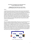
1
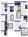
Troubleshooting Guide
Although the ProtoMat S62 and S100 are designed for years of trouble-free service, errors can always occur. The vast majority of problems
are easily solved within a minute or two of simple troubleshooting. Please review the following list of potential problems, and their easy
solutions:
The ProtoMat is completely DOA, no lights, no motion, nothing.
Verify that the unit is plugged completely into an operating socket
(sometimes adjusting the unit’s position can work the plug free).
Verify that all fuses or breakers in the mains power supply have not
been tripped. Verify that the fuse in the ProtoMat is good (a quick
check with an ohmmeter should reveal nearly 0 ohms resistance).
The ProtoMat appears to be on, and functioning, but completely
unresponsive to the host computer.
Verify that the RS-232 cable is firmly connected to both the ProtoMat
and the host computer. Verify that the COM port settings in
BoardMaster are in sync with the COM port settings in Windows (see
Connecting a ProtoMat to a computer). Reboot the computer and try
again.
BoardMaster reports “Error #E115” (figure 27)
Holes are not drilled centered on solder pads when board is flipped
to side 2.
If the ProtoMat has a fiducial recognition camera, the camera has
probably gone slightly out of alignment. Recalibrate the camera (see
Set/Calibrate camera offset).
If the ProtoMat does not have a camera, then the set pins have
become worn and new set pin holes must be drilled. See the User
Manual for this procedure.
There is some problem with the Fiducial Recognition Camera -- no
image, faulty image, etc.
Please refer to the installation manual for the Fiducial Recognition
Camera to troubleshoot camera errors.
The ProtoMat reports a “Filter full” error.
Verify that the data cable is securely connected
to both the ProtoMat and the dust extraction
unit.
If the problem persists, replace the filter bag.
30. Filter full error
The ProtoMat reports a “Cover is opened” error.
Close the cover.
27. Error #E115
Verify that the RS-232 cable is firmly connected to both the ProtoMat
and the host computer. Verify that the COM port settings in
BoardMaster are in sync with the COM port settings in Windows (see
Connecting a ProtoMat to a computer). Reboot the computer and try
again.
BoardMaster reports a “Voltage too low” error
Disconnect the ProtoMat from the mains power and verify that
the fuseblock is properly oriented for the existing mains voltage
supply. The proper voltage should be upright on the fuseblock (see
Unpacking and Installing the ProtoMat).
The ProtoMat reports a “Wrong ID” or “Can’t read from Calib_Result.
tbl” error
28. Wrong ID error
29. Can’t read cal table error
Copy the two files from the Configuration Files CD-ROM to
C:/Program Files//lpkf[xx]/bmaster/ ([xx] represents
a two-character code) and if there are already files of that name
present, overwrite those files. If this problem persists, contact LPKF
Technical support (see below).
The ProtoMat fails to pick up, or put away a tool, or there is a tool
collision
• Make sure all tools are properly seated in the sockets.
• Lubricate all tool tings using a silicon, graphite, Teflon, or other
suitable lubricant.
• Recalibrate the toolbar (see Adjusting the toolbar position
above).
31. Cover open error
Additional troubleshooting guides and tips can be found in the User
Manual, and online at
http://www.lpkfusa.com/ or http://www.protomat.
com/ and if none of these actions corrects the error, contact LPKF at
[email protected] or by calling (503) 454-4229.
ProtoMat® S62
ProtoMat® S100
Quick Start Guide
12. Checking the toolbar position
After the toolbar is loaded, check the toolbar position:
1. In BoardMaster, select the #1 tool
from the Selected Tool drop-down box
(figure 18).
2. As tool is selected, monitor the drill
head and make sure that the tool is
cleanly lifted from the tool bar without
scraping or catching, and that the tool
does not fall from the collet after lifting.
3. Repeat steps 1 and 2 for all ten tools.
Monitor each tool as it’s replaced,
18. Selecting tool #1
making sure that it is replaced firmly
into the toolbar, at the same level as the other tools, upright, and
smoothly, without catching or scraping against any part of the
ProtoMat.
Any tool position that exhibits scraping, catching, dropping, or other
signs of misalignment must be adjusted (see Adjusting the toolbar
position).
13. Adjusting the toolbar position
Adjust the toolbar position only if indicated by a misaligned tool or other
calibration error. Adjusting the tool position is sometimes necessary,
due to normal operating fluctuations such as
movement, temperature changes, and humidity
changes.
There are two different procedures, depending
on if a camera is installed. Refer to the Users
Manual for more detailed explanations.
19. The Measure Insert
in position #1
If there is a camera installed:
1. Set the Camera Offset (see Set/Calibrate camera offset).
2. Turn the ProtoMat on, send the machine head to the “Pause”
position, and remove all tools from the tool magazine.
3. Place the brass Measure Insert into tool position #1 (figure 19)
and close the hood.
20. Choosing tool #1
4. In BoardMaster, select Configuration >> Toolbox..., click
on tool position #1 in the Tool
Box list (figure 20), and click
the “Service” button. When
prompted for the Service
password, enter BMASTER.
5. Click the “Check:(1)” button,
use the Z keys in the main
interface to focus the image
and the XY keys to center
the crosshairs directly over
the tool position (figure 21).
Click “Accept” button when
21. The Measure Insert in the camera.
finished.
6. Repeat steps 3 through 5 for the remaining tool positions.
7. Close the Tool Box dialogue by clicking “OK” and send the
machine head to the “Pause” position.
8. Reinstall the tools in the tool magazine and restart BoardMaster.
If there is no camera installed:
1. Turn the ProtoMat on and make sure that there is a tool in every
slot of the tool magazine, and that there are no tools in the
ProtoMat’s collet.
2. In BoardMaster, select Configuration >> Heads..., choose
Camera under the Head drop-down box, and set both offset
values to 0, and click “OK”.
3. In BoardMaster, select Configuration >> Toolbox...,
click on tool position #1, and click the “Service” button. When
prompted for the Service password, enter BMASTER.
4. Under “Main/Aux. Clamp”, select “Open”, click on tool position
#1 in the Tool Box list, and click the “Check” button.
5. In the main BoardMaster interface, enter 35 in the step-size
window for the Z axis and click the Z axis down button. If a
dialogue box opens asking to set up a movement border, this
is normal. Click “Yes”. The machine head will lower and if
the head is properly aligned, the machine head will drop to the
bottom without sticking, or dislodging the tool. Click the Z axis
up button and the head should rise back to the original position
without sticking or dislodging the tool.
6. If the head is not properly adjusted, use 0.1 mm increments on
the manual X/Y controls to adjust the head until step 5 can be
completed smoothly without the tool or the head sticking.
7. Click the “Accept” button and repeat steps 3 through 6 for each
tool position on the tool magazine.
8. Close the tool box dialogue by clicking “OK” and restart
BoardMaster.
Thank You!
Thank you for purchasing an LPKF ProtoMat Circuit Board Plotter. ProtoMat circuit board plotters are key elements of any in-house
production, from precision one-off prototyping to short-run production.
Ensure years of solid performance by following the setup and installation instructions in this Quick-Start Guide carefully, and review the more
extensive documentation supplied with the ProtoMat when referred.
ProtoMat Anatomy
Hood
Milling motor
22. Measuring the actual hole diameter
A: click here first.
B: click here second.
C: read measured value.
Machining head
Vacuum hose
Fiducial recognition camera
Working depth limiter
Tool position #1
Vacuum table
Workpiece
14. Set/Calibrate camera offset
The camera offset must be adjusted and calibrated the first time the
ProtoMat is used, any time the camera is replaced, or any time the
offset is in question.
1. Set up a piece of scrap board material in the working area, switch
on the ProtoMat, and use BoardMaster to manually select a 1.5
mm drill and drill a single hole in the scrap material. Do not move
the machine head after drilling.
2. In BoardMaster, select Configuration >> Heads..., select
the Camera and click “Origin”, then “OK”.
3. In the BoardMaster menu, select Go to >> Camera >>
Head and use the manual XY controls to move the head such
that the crosshairs are as directly centered on the visible hole as
possible (For better precision, decrease the step width to 0.005
mm). Use the Z controls to bring the image into as clear a focus
as possible and press the “Set Focus” button.
4. When the crosshairs are as centered as possible, in BoardMaster,
select Configuration >> Heads..., click the “Head” button,
and then click “OK” to lock the new offset.
5. In the Camera Image window, click “Settings” to open the Setting
window. Adjust
the Brightness
and Contrast
to create a
strong contrast
between the
C
edges of the
hole and the
background of
the work piece
(figure 22).
A
B
Ideally, the hole
should be black
and the work
piece light gray.
Spring head and adjustment
Tool magazine
Case
Tool position #10
Power switch and
fuseblock located
behind side cover.
For clear access,
remove side cover
(8 screws).
Setting options:
Fuseblock settings
Machine table
(under vacuum table)
110/115 V
Shipping Checklist
Verify the following items are included with the S62 or S100:
•
•
•
•
•
•
•
•
•
•
Circuit board plotter and pre-assembled hood
Data cable (9-pin PC to RJ45 ProtoMat cable)
Power cable (standard power supply cable)
ProtoMat user manual (includes BoardMaster operations)
CircuitCAM user manual
CD-ROM with BoardMaster and CircuitCAM software
CD-ROM with Configuration Files
CD-ROM tutorial
Base material (connected to machine base plate)
Accessory set (tools, drills, fuses, and depth limiter foot)
Other References
Please review all documentation, including printed material and the CD-ROM tutorial, for more details.
Online support: http://www.lpkfusa.com/ and http://www.protomat.com/ and [email protected]
220/240 V
Startup Procedure
1. Unpacking and Installing the ProtoMat
1. Unpack the ProtoMat by removing
the cardboard cover, the accessory
bag, pulling out the foam inserts,
pulling the box sidewalls up and
away, and removing the protective
plastic wrap (figure 1).
1. Note the printed installation guide
2. Lift the ProtoMat as indicated in
the User Guide (do not use the exhaust tube as a handle!) and
place it onto a sturdy, flat, and level surface, strong enough to
support 55 kg (121 lbs).
3. Remove the shipping braces (three
pieces), and any stray adhesive or foam.
4. Verify that the ProtoMat’s fuseblock
(remove blue side cover for access) is
correctly set for the operating region’s
2. Removing the fuseblock
voltage. The fuseblock can be set for
110/120 volts or 220/240 volts. Whichever voltage reads upright
is the set voltage (figure 2 - currently set for 220/240 V). If the
value must be changed, pry the fuseblock out and reinsert it in
the correct orientation.
2. Connecting air supply (S100 only)
If the unit is an S100, connect the air supply (6 bar
@ 100 l/min or 87 psi @ 3.5 cfm) to the connector,
which is located inside the back access slot, near
the top of the opening (figure 3).
3. Air supply connection
3. Connecting dust extraction system
The dust extraction system keeps the
work area clean of dust and debris, and
is controlled by the ProtoMat.
1. Mount the dust extraction system
near the ProtoMat and connect
the exhaust tube to the side of the
black dust extraction manifold in
the back of the ProtoMat.
2. Connect the 9-pin side of the
4. The 9-pin connector
control cable (figure 4) to the dust
extraction unit and the 25-pin
side (figure 5) to an open 25-pin
connector in the back of the ProtoMat
(either connector will work).
3. Set the dust extraction unit control to
“auto” and connect the unit to main
power.
5. The 25-pin connector.
Either socket will work.
4. Installing depth limiter
The machine depth limiter must be
installed by hand. Press the foot
upward into the working area of the
machine head until it pops into place
(figure 6)
6. Installing the depth limiter.
7. Switching the ProtoMat on
5. Installing software
Install CircuitCAM and BoardMaster to the host computer, referring
to the User Guide where needed for troubleshooting. Note that the
installation CD has to be initially located, and note all installation
directories for future reference.
6. Connecting a ProtoMat to a computer
Connecting the ProtoMat
to a host computer varies
slightly, depending on if the
connection is via RS-232
interface or a USB port.
USB port installation:
1. Install the drivers for
the USB-to-serial
converter, according to
7. USB-to-Serial converter kit
the directions included
with the unit (figure 7).
2. Connect one end of the USB-to-serial converter to the USB port
of the host computer, and the other end to the serial cable of the
ProtoMat.
3. Switch the host computer on. After a minute or so, the computer
will register a new virtual COM port. Continue with the serial port
installation instructions below:
Serial port installation:
1. Connect the ProtoMat to
the host computer using the
included RS-232 serial cable
(if it’s not already). Make sure
that the proper COM port
is selected in Windows by
clicking Start >> Control
Panel >> System >>
Hardware >> Device
Manager, expand the Ports 8. Communication port settings (Windows)
setting, right-click the COM1 port, choose Properties and
clicking Port Settings, and that the port settings match those
shown in Figure 8.
2. Click Advanced... and make sure the FIFO settings are as
shown in Figure 9.
9. FIFO settings (Windows)
Assuring a trouble-free connection to the host computer is one of the
most important first steps. Refer to the troubleshooting section of this
Quick-Start Guide, and the troubleshooting section of the User Manual,
for more detail. Make absolutely certain all COM settings match and
that all cables are securely connected.
Caution! Do not operate ProtoMat unless the lid is closed securely and all objects, including tools, hands, etc. are clear of the working area. Overriding the safety mechanism or
leaving stray parts in the work area can result in damage to the machine or personal injury.
The basic switch-on procedure is:
1. Verify that there are no foreign
objects in the enclosed working
are of the ProtoMat, including
tools, unsecured working
material, etc.
2. Boot the host computer.
3. Switch on the ProtoMat.
4. Close the ProtoMat hood.
5. Start BoardMaster and complete 10. The Tool Status dialog box
the Tool Status
dialog box (figure
10 -- usually the
“Free tool position”
is 0)
6. If this is the first
time the ProtoMat
has been turned
on, or if the data
connection is in
doubt, make sure
BoardMaster refers
to the proper COM
port by clicking
in BoardMaster’s
menu
11. Communication port settings (BoardMaster)
Configuration
>> Connect... and verify that the settings match Window’s
COM settings (figure 11)
6. Verify that the ProtoMat machine head moves to the “Home”
position.
8. Checking basic functions
Checking basic functions normally only has to be done the first time the
machine is switched on, or if the machine has been moved.
1. If this is the first time the ProtoMat is switched on, make sure
there are no tools in the tool collet and no tools in the tool tray.
2. Switch on the ProtoMat, following the above procedure.
3. If the machine head was not already in the “Home” position, it
will automatically seek out the “Home” position by hunting for
limit switches. This may take a moment. Wait until the head
completely stops moving before continuing.
4. In the BoardMaster interface, click the “Pause” button
(figure 12) and verify that the machine head moves to
12. Pause
the “Pause” position.
5. Click the “Zero Position” button (figure
13) and verify the machine head moves
Zero/
into the Zero Position (or Tool Exchange) 13.
Tool Exchange
position.
14. Home
6. Click the “Home” button (figure 14) and verify that the
machine head moves into the “Home” position.
10. Installing camera (if included)
Installing the optional camera is also easy, and only requires an open
USB 2.0 port on the host computer. Refer to the included video
training and the User Manual for more details. The basic steps are:
1. Install the camera software on the host computer.
2. Remove the heatsink plate on the machine head and screw the
camera to the machine head.
3. Connect the camera power supply cable
to the socket on the machine head
(figure 15).
4. Run the camera USB cable up along
the exhaust hose using the supplied
brackets, and out through the back of
the ProtoMat. Be sure the connection
15. Camera power cable
to the camera and the connection to the
host computer’s USB port are solid.
5. Adjust the spring setting of the machining head by carefully
following the directions in the User Manual and training video.
6. Switch the ProtoMat on, using the above procedure. The
computer will discover new hardware twice (once for audio, once
for video) and install the camera. After this, in the BoardMaster
menu, choose Configuration >> Settings... >>
Unlock. Check the “Camera” checkbox, then click “OK”. Two
additional video windows will open in BoardMaster. If the Tool
status dialog box opens, verify and complete that information.
7. Restart BoardMaster.
11. Loading the tool magazine
Tool position #1
The ProtoMat ships with a
Tool position #10
basic tool Starter Package,
containing a variety of useful
tools for drilling, milling, and
routing PCBs in a variety
of material. It is critical
that the tool magazine be
loaded correctly, and that
16. The ten tool positions
BoardMaster be properly
configured.
1. Turn the ProtoMat on and in BoardMaster, click the
“Opens Toolbox dialogue” button. If asked about
placing the machine head in the “Pause” position,
choose “Yes”.
2. The tools should be inserted one at a time into the tool magazine,
according to figures 16 and 17. Each tool may be labeled in the
case, but may not individually labeled, so be especially careful to
not mix tools. As each tool is inserted into the magazine, choose
the same tool from the respective drop-down box in BoardMaster.
3. When all ten tools have been inserted, the Tool Positions dialogue
box should look like Figure 17:
4. Click the “OK” button and BoardMaster will change the
representative colors of the tools on the main interface to
accurately reflect the tool types loaded in the magazine. Restart
BoardMaster.
9. Installing vacuum table (if included)
If the vacuum table is not already installed, follow the included
installation instructions. Installing the optional vacuum table is quick
and easy. Refer to the included video training and the User Manual for
more details.
17. Tool positions dialog box, showing initial settings for all tools.
12. Checking the toolbar position
After the toolbar is loaded, check the toolbar position:
1. In BoardMaster, select the #1 tool
from the Selected Tool drop-down box
(figure 18).
2. As tool is selected, monitor the drill
head and make sure that the tool is
cleanly lifted from the tool bar without
scraping or catching, and that the tool
does not fall from the collet after lifting.
3. Repeat steps 1 and 2 for all ten tools.
Monitor each tool as it’s replaced,
18. Selecting tool #1
making sure that it is replaced firmly
into the toolbar, at the same level as the other tools, upright, and
smoothly, without catching or scraping against any part of the
ProtoMat.
Any tool position that exhibits scraping, catching, dropping, or other
signs of misalignment must be adjusted (see Adjusting the toolbar
position).
13. Adjusting the toolbar position
Adjust the toolbar position only if indicated by a misaligned tool or other
calibration error. Adjusting the tool position is sometimes necessary,
due to normal operating fluctuations such as
movement, temperature changes, and humidity
changes.
There are two different procedures, depending
on if a camera is installed. Refer to the Users
Manual for more detailed explanations.
19. The Measure Insert
in position #1
If there is a camera installed:
1. Set the Camera Offset (see Set/Calibrate camera offset).
2. Turn the ProtoMat on, send the machine head to the “Pause”
position, and remove all tools from the tool magazine.
3. Place the brass Measure Insert into tool position #1 (figure 19)
and close the hood.
20. Choosing tool #1
4. In BoardMaster, select Configuration >> Toolbox..., click
on tool position #1 in the Tool
Box list (figure 20), and click
the “Service” button. When
prompted for the Service
password, enter BMASTER.
5. Click the “Check:(1)” button,
use the Z keys in the main
interface to focus the image
and the XY keys to center
the crosshairs directly over
the tool position (figure 21).
Click “Accept” button when
21. The Measure Insert in the camera.
finished.
6. Repeat steps 3 through 5 for the remaining tool positions.
7. Close the Tool Box dialogue by clicking “OK” and send the
machine head to the “Pause” position.
8. Reinstall the tools in the tool magazine and restart BoardMaster.
If there is no camera installed:
1. Turn the ProtoMat on and make sure that there is a tool in every
slot of the tool magazine, and that there are no tools in the
ProtoMat’s collet.
2. In BoardMaster, select Configuration >> Heads..., choose
Camera under the Head drop-down box, and set both offset
values to 0, and click “OK”.
3. In BoardMaster, select Configuration >> Toolbox...,
click on tool position #1, and click the “Service” button. When
prompted for the Service password, enter BMASTER.
4. Under “Main/Aux. Clamp”, select “Open”, click on tool position
#1 in the Tool Box list, and click the “Check” button.
5. In the main BoardMaster interface, enter 35 in the step-size
window for the Z axis and click the Z axis down button. If a
dialogue box opens asking to set up a movement border, this
is normal. Click “Yes”. The machine head will lower and if
the head is properly aligned, the machine head will drop to the
bottom without sticking, or dislodging the tool. Click the Z axis
up button and the head should rise back to the original position
without sticking or dislodging the tool.
6. If the head is not properly adjusted, use 0.1 mm increments on
the manual X/Y controls to adjust the head until step 5 can be
completed smoothly without the tool or the head sticking.
7. Click the “Accept” button and repeat steps 3 through 6 for each
tool position on the tool magazine.
8. Close the tool box dialogue by clicking “OK” and restart
BoardMaster.
Thank You!
Thank you for purchasing an LPKF ProtoMat Circuit Board Plotter. ProtoMat circuit board plotters are key elements of any in-house
production, from precision one-off prototyping to short-run production.
Ensure years of solid performance by following the setup and installation instructions in this Quick-Start Guide carefully, and review the more
extensive documentation supplied with the ProtoMat when referred.
ProtoMat Anatomy
Hood
Milling motor
22. Measuring the actual hole diameter
A: click here first.
B: click here second.
C: read measured value.
Machining head
Vacuum hose
Fiducial recognition camera
Working depth limiter
Tool position #1
Vacuum table
Workpiece
14. Set/Calibrate camera offset
The camera offset must be adjusted and calibrated the first time the
ProtoMat is used, any time the camera is replaced, or any time the
offset is in question.
1. Set up a piece of scrap board material in the working area, switch
on the ProtoMat, and use BoardMaster to manually select a 1.5
mm drill and drill a single hole in the scrap material. Do not move
the machine head after drilling.
2. In BoardMaster, select Configuration >> Heads..., select
the Camera and click “Origin”, then “OK”.
3. In the BoardMaster menu, select Go to >> Camera >>
Head and use the manual XY controls to move the head such
that the crosshairs are as directly centered on the visible hole as
possible (For better precision, decrease the step width to 0.005
mm). Use the Z controls to bring the image into as clear a focus
as possible and press the “Set Focus” button.
4. When the crosshairs are as centered as possible, in BoardMaster,
select Configuration >> Heads..., click the “Head” button,
and then click “OK” to lock the new offset.
5. In the Camera Image window, click “Settings” to open the Setting
window. Adjust
the Brightness
and Contrast
to create a
strong contrast
between the
C
edges of the
hole and the
background of
the work piece
(figure 22).
A
B
Ideally, the hole
should be black
and the work
piece light gray.
Spring head and adjustment
Tool magazine
Case
Tool position #10
Power switch and
fuseblock located
behind side cover.
For clear access,
remove side cover
(8 screws).
Setting options:
Fuseblock settings
Machine table
(under vacuum table)
110/115 V
Shipping Checklist
Verify the following items are included with the S62 or S100:
•
•
•
•
•
•
•
•
•
•
Circuit board plotter and pre-assembled hood
Data cable (9-pin PC to RJ45 ProtoMat cable)
Power cable (standard power supply cable)
ProtoMat user manual (includes BoardMaster operations)
CircuitCAM user manual
CD-ROM with BoardMaster and CircuitCAM software
CD-ROM with Configuration Files
CD-ROM tutorial
Base material (connected to machine base plate)
Accessory set (tools, drills, fuses, and depth limiter foot)
Other References
Please review all documentation, including printed material and the CD-ROM tutorial, for more details.
Online support: http://www.lpkfusa.com/ and http://www.protomat.com/ and [email protected]
220/240 V
Specifications
6. Measure the diameter of the hole in the Camera Image window
(figure 22). Note that this measured value will probably be
incorrect.
7. Complete the Fiducial settings accordingly (figure 23):
Specification
ProtoMat S62
ProtoMat S100
Part #
115788
116664
Working area (X/Y/Z)
229 x 305 x 38 mm (9” x 2” x .5”)
229 x 305 x 38 mm (9” x 2” x .5”)
Resolution (X/Y)
0.25 µm (0.0 mil)
0.25 µm (0.0 mil)
Repeatability
±0.001 mm (±0.04 mil)
±0.001 mm (±0.04 mil)
Precision of
front-to-back alignment
±0.02 mm (±0.8 mil)
±0.02 mm (±0.8 mil)
Milling motor
Max. 62,000 rpm, software controlled
Max. 100,000 rpm, software controlled
Tool change
Automatic, 10 positions
Automatic, 10 positions
Tool collet
3.175 mm (1/8”)
3.175 mm (1/8”), pneumatic release collet
Drilling speed
150 strokes/minute
150 strokes/minute
Travel speed (max)
Max. 150 mm/second (6”/second)
Max. 150 mm/second (6”/second)
X/Y positioning system
3-phase stepper motors
3-phase stepper motors
Z drive
Stepper motor
Stepper motor
Dimensions (W/H/D)
670 x 540 x 760 mm
(26.4” x 21.3” x 29.9”)
670 x 540 x 760 mm
(26.4” x 21.3” x 29.9”)
accurate diameter, and
the crosshairs are properly
centered on the hole
(figure 26). If the camera
is still miscalibrated
(extremely rare) or the
offset still questionable,
repeat steps 2 through 12.
14. Restart BoardMaster.
26. Perfectly calibrated
Weight
55 kg (121 lb)
55 kg (121 lb)
Power supply
115/230 V, 50–60 Hz, 200 W
115/230 V, 50–60 Hz, 200 W
Compressed air supply
Not required
6 bar (87 psi), 100 l/min (3.528 cfm)
Specifications subject to change.
Size of tracks and gaps depends on materials and tools.
100 µm tracks and gaps possible with LPKF MicroCutter on FR4 18/18 µm Cu.
Extras
Enhance the operation of the ProtoMat S62 or S100 with these high-quality accessories, tools, and consumables:
Dust Extraction System
Measuring Microscope
System Status Light
Brush Head
Basic Starter Set
Multilayer Starter Set
Base Material
Professional Tooling
15. Finished!
The ProtoMat is now ready for use!
23. Entering the measured values (for example, 1.44 mm). Note that
Minimal quality is set to 70% only for calibration and is normally 90%.
• Fiducial diameter: use the measured value from step #6
• Number of fiducials: 1
• Minimal diameter: the measured value from step #6 minus
0.1 mm
• Minimal quality: 90%
8. In the Fiducial settings section of the Setting window, click the
“Accept” button.
9. If the calibration is unsuccessful,
try lowering the minimal quality
to 70% and clicking “Accept”
again. Adjusting the Brightness
and Contrast to create more
contrast may help as well.
Repeat until the calibration is
successful and the Calibration
window appears (figure 24).
10. Complete the Calibration window
(enter either radius or diameter
24. Calibration window
and the other value will populate
automatically), and click “OK”. The calibration should be
successful (if not, then repeat step 9), and the alert window
can be dismissed by clicking “OK”.
11. In the Fiducial settings section of the Setting window, enter the
proper values accordingly (figure 25):
• Fiducial diameter: 1.5
• Number of fiducials: 1
• Minimal diameter: 1.4
• Minimal quality: 90%
For more tutorials, tips, and how-to’s, see LPKF’s latest
Rapid PCB Prototyping catalog, featuring an extensive
technical guide designed to enhance and in-house
prototyping laboratory. The Technical Guide includes
tutorials and overviews on:
•
•
•
•
•
•
•
•
•
•
•
•
•
25. Entering the corrected values and setting Minimal quality to 90%
Check with your local LPKF distributor for these and other accessories to help create the perfect prototyping solution.
Also, check online at http://www.lpkfusa.com or call (503) 454-4233 or 1-(800) 345-5753.
Additional Tutorials and How-to’s
12. Click “Accept” to set the new values and close the Setting
window by clicking “OK”.
13. Using the same technique from step 6, remeasure the drill
hole and verify that the Camera Image window now reports the
Base Material Overview
Application Review
Compatibility Grid
CircuitCAM Overview
BoardMaster Overview
Basic 2-Layer Board Building Tutorial
Chemical-Free Through-Hole Plating Tutorial
Galvanic Plating Overview
Multilayer PCB Overview and Tutorial
Professional Solder Mask Tutorial
Surface Mount Technology Overview and Tutorial
Microwave and RF Application Notes
Plastics and Aluminum Engraving
For the latest copy, visit http://www.lpkfusa.com
or contact your local distributor.
Troubleshooting Guide
Although the ProtoMat S62 and S100 are designed for years of trouble-free service, errors can always occur. The vast majority of problems
are easily solved within a minute or two of simple troubleshooting. Please review the following list of potential problems, and their easy
solutions:
The ProtoMat is completely DOA, no lights, no motion, nothing.
Verify that the unit is plugged completely into an operating socket
(sometimes adjusting the unit’s position can work the plug free).
Verify that all fuses or breakers in the mains power supply have not
been tripped. Verify that the fuse in the ProtoMat is good (a quick
check with an ohmmeter should reveal nearly 0 ohms resistance).
The ProtoMat appears to be on, and functioning, but completely
unresponsive to the host computer.
Verify that the RS-232 cable is firmly connected to both the ProtoMat
and the host computer. Verify that the COM port settings in
BoardMaster are in sync with the COM port settings in Windows (see
Connecting a ProtoMat to a computer). Reboot the computer and try
again.
BoardMaster reports “Error #E115” (figure 27)
Holes are not drilled centered on solder pads when board is flipped
to side 2.
If the ProtoMat has a fiducial recognition camera, the camera has
probably gone slightly out of alignment. Recalibrate the camera (see
Set/Calibrate camera offset).
If the ProtoMat does not have a camera, then the set pins have
become worn and new set pin holes must be drilled. See the User
Manual for this procedure.
There is some problem with the Fiducial Recognition Camera -- no
image, faulty image, etc.
Please refer to the installation manual for the Fiducial Recognition
Camera to troubleshoot camera errors.
The ProtoMat reports a “Filter full” error.
Verify that the data cable is securely connected
to both the ProtoMat and the dust extraction
unit.
If the problem persists, replace the filter bag.
30. Filter full error
The ProtoMat reports a “Cover is opened” error.
Close the cover.
27. Error #E115
Verify that the RS-232 cable is firmly connected to both the ProtoMat
and the host computer. Verify that the COM port settings in
BoardMaster are in sync with the COM port settings in Windows (see
Connecting a ProtoMat to a computer). Reboot the computer and try
again.
BoardMaster reports a “Voltage too low” error
Disconnect the ProtoMat from the mains power and verify that
the fuseblock is properly oriented for the existing mains voltage
supply. The proper voltage should be upright on the fuseblock (see
Unpacking and Installing the ProtoMat).
The ProtoMat reports a “Wrong ID” or “Can’t read from Calib_Result.
tbl” error
28. Wrong ID error
29. Can’t read cal table error
Copy the two files from the Configuration Files CD-ROM to
C:/Program Files//lpkf[xx]/bmaster/ ([xx] represents
a two-character code) and if there are already files of that name
present, overwrite those files. If this problem persists, contact LPKF
Technical support (see below).
The ProtoMat fails to pick up, or put away a tool, or there is a tool
collision
• Make sure all tools are properly seated in the sockets.
• Lubricate all tool tings using a silicon, graphite, Teflon, or other
suitable lubricant.
• Recalibrate the toolbar (see Adjusting the toolbar position
above).
31. Cover open error
Additional troubleshooting guides and tips can be found in the User
Manual, and online at
http://www.lpkfusa.com/ or http://www.protomat.
com/ and if none of these actions corrects the error, contact LPKF at
[email protected] or by calling (503) 454-4229.
ProtoMat® S62
ProtoMat® S100
Quick Start Guide
Specifications
6. Measure the diameter of the hole in the Camera Image window
(figure 22). Note that this measured value will probably be
incorrect.
7. Complete the Fiducial settings accordingly (figure 23):
Specification
ProtoMat S62
ProtoMat S100
Part #
115788
116664
Working area (X/Y/Z)
229 x 305 x 38 mm (9” x 2” x .5”)
229 x 305 x 38 mm (9” x 2” x .5”)
Resolution (X/Y)
0.25 µm (0.0 mil)
0.25 µm (0.0 mil)
Repeatability
±0.001 mm (±0.04 mil)
±0.001 mm (±0.04 mil)
Precision of
front-to-back alignment
±0.02 mm (±0.8 mil)
±0.02 mm (±0.8 mil)
Milling motor
Max. 62,000 rpm, software controlled
Max. 100,000 rpm, software controlled
Tool change
Automatic, 10 positions
Automatic, 10 positions
Tool collet
3.175 mm (1/8”)
3.175 mm (1/8”), pneumatic release collet
Drilling speed
150 strokes/minute
150 strokes/minute
Travel speed (max)
Max. 150 mm/second (6”/second)
Max. 150 mm/second (6”/second)
X/Y positioning system
3-phase stepper motors
3-phase stepper motors
Z drive
Stepper motor
Stepper motor
Dimensions (W/H/D)
670 x 540 x 760 mm
(26.4” x 21.3” x 29.9”)
670 x 540 x 760 mm
(26.4” x 21.3” x 29.9”)
accurate diameter, and
the crosshairs are properly
centered on the hole
(figure 26). If the camera
is still miscalibrated
(extremely rare) or the
offset still questionable,
repeat steps 2 through 12.
14. Restart BoardMaster.
26. Perfectly calibrated
Weight
55 kg (121 lb)
55 kg (121 lb)
Power supply
115/230 V, 50–60 Hz, 200 W
115/230 V, 50–60 Hz, 200 W
Compressed air supply
Not required
6 bar (87 psi), 100 l/min (3.528 cfm)
Specifications subject to change.
Size of tracks and gaps depends on materials and tools.
100 µm tracks and gaps possible with LPKF MicroCutter on FR4 18/18 µm Cu.
Extras
Enhance the operation of the ProtoMat S62 or S100 with these high-quality accessories, tools, and consumables:
Dust Extraction System
Measuring Microscope
System Status Light
Brush Head
Basic Starter Set
Multilayer Starter Set
Base Material
Professional Tooling
15. Finished!
The ProtoMat is now ready for use!
23. Entering the measured values (for example, 1.44 mm). Note that
Minimal quality is set to 70% only for calibration and is normally 90%.
• Fiducial diameter: use the measured value from step #6
• Number of fiducials: 1
• Minimal diameter: the measured value from step #6 minus
0.1 mm
• Minimal quality: 90%
8. In the Fiducial settings section of the Setting window, click the
“Accept” button.
9. If the calibration is unsuccessful,
try lowering the minimal quality
to 70% and clicking “Accept”
again. Adjusting the Brightness
and Contrast to create more
contrast may help as well.
Repeat until the calibration is
successful and the Calibration
window appears (figure 24).
10. Complete the Calibration window
(enter either radius or diameter
24. Calibration window
and the other value will populate
automatically), and click “OK”. The calibration should be
successful (if not, then repeat step 9), and the alert window
can be dismissed by clicking “OK”.
11. In the Fiducial settings section of the Setting window, enter the
proper values accordingly (figure 25):
• Fiducial diameter: 1.5
• Number of fiducials: 1
• Minimal diameter: 1.4
• Minimal quality: 90%
For more tutorials, tips, and how-to’s, see LPKF’s latest
Rapid PCB Prototyping catalog, featuring an extensive
technical guide designed to enhance and in-house
prototyping laboratory. The Technical Guide includes
tutorials and overviews on:
•
•
•
•
•
•
•
•
•
•
•
•
•
25. Entering the corrected values and setting Minimal quality to 90%
Check with your local LPKF distributor for these and other accessories to help create the perfect prototyping solution.
Also, check online at http://www.lpkfusa.com or call (503) 454-4233 or 1-(800) 345-5753.
Additional Tutorials and How-to’s
12. Click “Accept” to set the new values and close the Setting
window by clicking “OK”.
13. Using the same technique from step 6, remeasure the drill
hole and verify that the Camera Image window now reports the
Base Material Overview
Application Review
Compatibility Grid
CircuitCAM Overview
BoardMaster Overview
Basic 2-Layer Board Building Tutorial
Chemical-Free Through-Hole Plating Tutorial
Galvanic Plating Overview
Multilayer PCB Overview and Tutorial
Professional Solder Mask Tutorial
Surface Mount Technology Overview and Tutorial
Microwave and RF Application Notes
Plastics and Aluminum Engraving
For the latest copy, visit http://www.lpkfusa.com
or contact your local distributor.