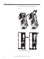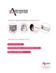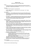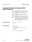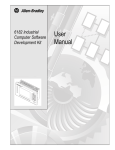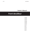
1
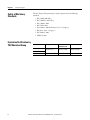
User Manual
PowerFlex® 750-Series Safe Torque Off
Catalog Number 20-750-S
Important User Information
Solid-state equipment has operational characteristics differing from those of electromechanical equipment. Safety
Guidelines for the Application, Installation and Maintenance of Solid State Controls (publication SGI-1.1 available from
your local Rockwell Automation sales office or online at http://www.rockwellautomation.com/literature/) describes some
important differences between solid-state equipment and hard-wired electromechanical devices. Because of this difference,
and also because of the wide variety of uses for solid-state equipment, all persons responsible for applying this equipment
must satisfy themselves that each intended application of this equipment is acceptable.
In no event will Rockwell Automation, Inc. be responsible or liable for indirect or consequential damages resulting from
the use or application of this equipment.
The examples and diagrams in this manual are included solely for illustrative purposes. Because of the many variables and
requirements associated with any particular installation, Rockwell Automation, Inc. cannot assume responsibility or
liability for actual use based on the examples and diagrams.
No patent liability is assumed by Rockwell Automation, Inc. with respect to use of information, circuits, equipment, or
software described in this manual.
Reproduction of the contents of this manual, in whole or in part, without written permission of Rockwell Automation,
Inc., is prohibited.
Throughout this manual, when necessary, we use notes to make you aware of safety considerations.
WARNING: Identifies information about practices or circumstances that can cause an explosion in a hazardous
environment, which may lead to personal injury or death, property damage, or economic loss.
ATTENTION: Identifies information about practices or circumstances that can lead to personal injury or death,
property damage, or economic loss. Attentions help you identify a hazard, avoid a hazard, and recognize the
consequence
SHOCK HAZARD: Labels may be on or inside the equipment, for example, a drive or motor, to alert people that
dangerous voltage may be present.
BURN HAZARD: Labels may be on or inside the equipment, for example, a drive or motor, to alert people that
surfaces may reach dangerous temperatures.
IMPORTANT
Identifies information that is critical for successful application and understanding of the product.
Allen-Bradley, Rockwell Software, Rockwell Automation, and TechConnect are trademarks of Rockwell Automation, Inc.
Trademarks not belonging to Rockwell Automation are property of their respective companies.
Summary of Changes
This manual contains new and updated information.
New and Updated
Information
This table contains the changes made to this revision.
Topic
Page
PowerFlex Frame 8 drive information added.
Throughout
PFD and PFH for 20-year Proof Test Interval table updated.
7
Details on hardware enable jumper added.
20
Port 6 installation requirement for Integrated Motion applications
added to Important statement.
22
Tip added explaning how module operation is verified.
24
Required jumper settings added to connection examples.
27…29
Rockwell Automation Publication 750-UM002C-EN-P - December 2010
3
Summary of Changes
4
Rockwell Automation Publication 750-UM002C-EN-P - December 2010
Table of Contents
Chapter 1
General Description
What Is the PowerFlex 750-Series Safe Torque Off Option? . . . . . . . . . . 7
Safety of Machinery Standards. . . . . . . . . . . . . . . . . . . . . . . . . . . . . . . . . . . . . . 8
Evaluation/Certification by TÜV Rheinland Group . . . . . . . . . . . . . . . . . 8
Chapter 2
Safety Concept
Introduction . . . . . . . . . . . . . . . . . . . . . . . . . . . . . . . . . . . . . . . . . . . . . . . . . . . . . . 9
Safety Certification . . . . . . . . . . . . . . . . . . . . . . . . . . . . . . . . . . . . . . . . . . . . . . . . 9
Functional Proof Tests. . . . . . . . . . . . . . . . . . . . . . . . . . . . . . . . . . . . . . . . . . . . 11
PFD and PFH Definitions . . . . . . . . . . . . . . . . . . . . . . . . . . . . . . . . . . . . . . . . 11
PFD and PFH Data . . . . . . . . . . . . . . . . . . . . . . . . . . . . . . . . . . . . . . . . . . . . . . 12
Safe State . . . . . . . . . . . . . . . . . . . . . . . . . . . . . . . . . . . . . . . . . . . . . . . . . . . . . . . . 12
Safety Reaction Time . . . . . . . . . . . . . . . . . . . . . . . . . . . . . . . . . . . . . . . . . . . . . 12
Considerations for Safety Ratings . . . . . . . . . . . . . . . . . . . . . . . . . . . . . . . . . . 13
Contact Information if Safety Option Failure Occurs . . . . . . . . . . . . . . . 13
Chapter 3
Installation and Wiring
Access Drive Control Pod. . . . . . . . . . . . . . . . . . . . . . . . . . . . . . . . . . . . . . . . .
Configure Safety Enable . . . . . . . . . . . . . . . . . . . . . . . . . . . . . . . . . . . . . . . . . .
Option Module Installation . . . . . . . . . . . . . . . . . . . . . . . . . . . . . . . . . . . . . . .
Wiring . . . . . . . . . . . . . . . . . . . . . . . . . . . . . . . . . . . . . . . . . . . . . . . . . . . . . . . . . .
Verify Operation . . . . . . . . . . . . . . . . . . . . . . . . . . . . . . . . . . . . . . . . . . . . . . . . .
16
19
22
23
24
Chapter 4
Description of Operation
PowerFlex 750-Series Safe Torque Off Operation . . . . . . . . . . . . . . . . . . . 25
Appendix A
Specifications
Introduction . . . . . . . . . . . . . . . . . . . . . . . . . . . . . . . . . . . . . . . . . . . . . . . . . . . . . 31
General Specifications . . . . . . . . . . . . . . . . . . . . . . . . . . . . . . . . . . . . . . . . . . . . 31
Certifications . . . . . . . . . . . . . . . . . . . . . . . . . . . . . . . . . . . . . . . . . . . . . . . . . . . . 31
Rockwell Automation Publication 750-UM002C-EN-P - December 2010
5
Table of Contents
6
Rockwell Automation Publication 750-UM002C-EN-P - December 2010
Chapter
1
General Description
The Safe Torque Off option is just one component in a safety control system.
Components in the system must be chosen and applied appropriately to achieve
the desired level of operational safety.
What Is the PowerFlex
750-Series Safe Torque Off
Option?
The PowerFlex 750-Series Safe Torque Off option:
• Is designed to help safely remove power from the gate firing circuits of the
drive’s output power devices (IGBT’s). This helps prevent the drive’s
output power devices from switching in the pattern necessary to generate
AC power to the motor.
• Can be used in combination with other safety devices to satisfy the
requirements of IEC 61508, IEC 61800-5-2 SIL 3, ISO 13849-1 PLe, and
Category 3 (EN 954-1) for Safe Torque Off (STO).
IMPORTANT
This option is suitable for performing mechanical work on the drive
system or affected area of a machine only. It does not provide electrical
safety.
This option should not be used as a control for starting and/or stopping
the drive.
ATTENTION: Electrical Shock Hazard. Verify that all sources of AC and
DC power are deenergized and locked out or tagged out in accordance
with the requirements of ANSI/NFPA 70E, Part II.
ATTENTION: To avoid an electric shock hazard, verify that the voltage on
the bus capacitors has discharged before performing any work on the
drive. Measure the DC bus voltage at the +DC and -DC terminals or test
points (refer to your drive’s User Manual for locations). The voltage must
be zero.
ATTENTION: In safe-off mode, hazardous voltages may still be present at
the motor. To avoid an electric shock hazard, disconnect power to the
motor and verify that the voltage is zero before performing any work on
the motor.
ATTENTION: In the event of the failure of two output IGBTs in the drive,
when the PowerFlex 750-Series Safe Torque Off option has controlled the
drive outputs to the off state, the drive may provide energy for up to 180°
of rotation in a 2-pole motor before torque production in the motor ceases.
Rockwell Automation Publication 750-UM002C-EN-P - December 2010
7
Chapter 1
General Description
Safety of Machinery
Standards
The Safe Torque Off option helps to satisfy requirements in the following
standards:
• IEC 61508: 2000 SIL 3
• IEC 61800-5-2: 2007 SIL 3
• IEC 61800-3: 2004
• IEC 62061: 2005
• ISO 13849-1: 2006 Performance Level e, Category 3
• EN 954-1: 1996 – Category 3
• IEC 60204-1: 2005
• NFPA 79: 2007
Evaluation/Certification by
TÜV Rheinland Group
Drive
PowerFlex 753
PowerFlex 755
PowerFlex 755
8
Rating
TÜV Report on
Safety Function
TÜV fs Certification
400/480V Frames 2…7
968/EZ 334.00/08
968/EZ 334.00/08
400/480V Frame 8
968/M 262.00/10
968/M 262.00/10
Rockwell Automation Publication 750-UM002C-EN-P - December 2010
Chapter
2
Safety Concept
Introduction
This section describes the safety performance level concept and how the
PowerFlex 750-Series drives can meet the requirements for SIL CL3, CAT 3, or
PL(e) applications.
Safety Certification
The PowerFlex 750-Series safety option is certified for use in safety applications
up to and including SIL 3 according to EN 61800-5-2, EN 61508, and EN
62061, Performance Level PL(e) and Category 3 according to ISO 13849-1.
Safety requirements are based on the standards current at the time of
certification.
The TÜV Rheinland group has approved the PowerFlex 750-Series safety option
for use in safety-related applications where the de-energized state is considered to
be the safe state. All of the examples in this manual are based on achieving
de-energization as the safe state for typical Machine Safety and Emergency
Shutdown (ESD) systems.
Important Safety Considerations
The system user is responsible for:
• the set-up, safety rating, and validation of any sensors or actuators
connected to the system.
• completing a system-level risk assessment and reassessing the system any
time a change is made.
• certification of the system to the desired safety performance level.
• project management and proof testing.
• programming the application software and the safety option
configurations in accordance with the information in this manual.
• access control to the system.
• analyzing all configuration settings and choosing the proper setting to
achieve the required safety rating.
IMPORTANT
When applying Functional Safety, restrict access to qualified, authorized
personnel who are trained and experienced.
ATTENTION: When designing your system, consider how personnel will
exit the machine if the door locks while they are in the machine.
Additional safeguarding devices may be required for your specific
application.
Rockwell Automation Publication 750-UM002C-EN-P - December 2010
9
Chapter 2
Safety Concept
Safety Category 3 Performance Definition
To achieve Safety Category 3 according to ISO 13849-1:2006, the safety-related
parts have to be designed such that:
• the safety-related parts of machine control systems and/or their protective
equipment, as well as their components, shall be designed, constructed,
selected, assembled, and combined in accordance with relevant standards
so that they can withstand expected conditions.
• basic safety principles shall be applied.
• a single fault in any of its parts does not lead to a loss of safety function.
• a single fault is detected at or before the next demand of the safety
function, or, if this detection is not possible, then an accumulation of faults
shall not lead to a loss of the safety function.
• the average diagnostic coverage of the safety-related parts of the control
system shall be high, including the accumulation of faults.
• the mean time to dangerous failure of each of the redundant channels shall
be high.
• measures against common cause failure shall be applied.
Stop Category Definitions
The selection of a stop category for each stop function must be determined by a
risk assessment.
• Stop Category 0 is achieved with immediate removal of power to the
actuator, resulting in an uncontrolled coast to stop. Safe Torque Off
accomplishes a Stop Category 0 stop.
• Stop Category 1 is achieved with power available to the machine actuators
to achieve the stop. Power is removed from the actuators when the stop is
achieved.
• Stop Category 2 is a controlled stop with power available to the machine
actuators. The stop is followed by a holding position under power.
IMPORTANT
10
When designing the machine application, timing and distance should be
considered for a coast to stop (Stop Category 0 or Safe Torque Off). For
more information regarding stop categories, refer to EN 60204-1.
Rockwell Automation Publication 750-UM002C-EN-P - December 2010
Safety Concept
Chapter 2
Performance Level and Safety Integrity Level (SIL) CL3
For safety-related control systems, Performance Level (PL), according to ISO
13849-1, and SIL levels, according to EN 61508 and EN 62061, include a rating
of the system’s ability to perform its safety functions. All of the safety-related
components of the control system must be included in both a risk assessment and
the determination of the achieved levels.
Refer to the ISO 13849-1, EN 61508, and EN 62061 standards for complete
information on requirements for PL and SIL determination.
Functional Proof Tests
The functional safety standards require that functional proof tests be performed
on the equipment used in the system. Proof tests are performed at user-defined
intervals and are dependent upon PFD and PFH values.
IMPORTANT
PFD and PFH Definitions
Your specific application determines the time frame for the proof test
interval.
Safety-related systems can be classified as operating in either a Low Demand
mode, or in a High Demand/Continuous mode.
• Low Demand mode: where the frequency of demands for operation made
on a safety-related system is no greater than one per year or no greater than
twice the proof-test frequency.
• High Demand/Continuous mode: where the frequency of demands for
operation made on a safety-related system is greater than once per year or
greater than twice the proof test interval.
The SIL value for a low demand safety-related system is directly related to
order-of-magnitude ranges of its average probability of failure to satisfactorily
perform its safety function on demand or, simply, average probability of failure on
demand (PFD). The SIL value for a High Demand/continuous mode
safety-related system is directly related to the probability of a dangerous failure
occurring per hour (PFH).
Rockwell Automation Publication 750-UM002C-EN-P - December 2010
11
Chapter 2
Safety Concept
PFD and PFH Data
PFD and PFH calculations are based on the equations from Part 6 of EN 61508.
This table provides data for a 20-year proof test interval and demonstrates the
worst-case effect of various configuration changes on the data.
PFD and PFH for 20-year Proof Test Interval
Attribute
Value
Drive Frames 2…7
Drive Frame 8
PFD
3.29E-5
3.81E-04
PFH
3.75E-10
4.46E-09
SFF
99.5%
98.4%
DC
99.5% (1)
90.0%
SIL CL
3
3
PL
e
e
CAT.
3
3
HFT
1 (1oo2)
1 (1oo2)
PTI (Proof Test Interval)
20 years
20 years
(1) Without connection to external equipment.
Safe State
The Safe State encompasses all operation that occurs outside of the other
monitoring and stopping behavior defined as part of the Safe Torque Off Option
module.
If a Safe State Fault is detected, the safety option goes to the Safe State. This
includes faults related to integrity of hardware or firmware.
Safety Reaction Time
The safety reaction time is the amount of time from a safety-related event as
input to the system until the system is in the Safe State.
The safety reaction time from an input signal condition that triggers a safe stop,
to the initiation of the configured Stop Type, is:
• 20 ms (maximum) for drive Frames 2…7
• 20.8 ms (maximum) for drive Frame 8
12
Rockwell Automation Publication 750-UM002C-EN-P - December 2010
Safety Concept
Considerations for Safety
Ratings
Chapter 2
The achievable safety rating of an application using the safety option installed in
PowerFlex 750-Series drives is dependent upon many factors, drive options, and
the type of motor.
For applications that rely on the immediate removal of power to the actuator,
resulting in an uncontrolled coast to stop, a safety rating up to and including SIL
CL3, PL(e), and Category 3 can be achieved.
Contact Information if
Safety Option Failure
Occurs
If you experience a failure with any safety-certified device, contact your local
Rockwell Automation distributor. With this contact, you can:
• return the device to Rockwell Automation so the failure is appropriately
logged for the catalog number affected and a record is made of the failure.
• request a failure analysis (if necessary) to determine the probable cause of
the failure.
Rockwell Automation Publication 750-UM002C-EN-P - December 2010
13
Chapter 2
Safety Concept
Notes:
14
Rockwell Automation Publication 750-UM002C-EN-P - December 2010
Chapter
3
Installation and Wiring
Installation must be in accordance with the following steps and must be carried
out by competent personnel. The Safe Torque Off option is intended to be part of
the safety related control system of a machine. Before installation, a risk
assessment should be performed that compares the Safe Torque Off option
specifications and all foreseeable operational and environmental characteristics of
the machine to which it is to be fitted.
A safety analysis of the machine section controlled by the drive is required to
determine how often the safety function should be tested for proper operation
during the life of the machine.
ATTENTION: The following information is merely a guide for proper
installation. Rockwell Automation, Inc. cannot assume responsibility for
the compliance or the noncompliance to any code, national, local or
otherwise for the proper installation of this equipment. A hazard of
personal injury and/or equipment damage exists if codes are ignored
during installation.
Rockwell Automation Publication 750-UM002C-EN-P - December 2010
15
Chapter 3
Installation and Wiring
Access Drive Control Pod
1. Remove drive cover.
Frames 2…5.
– Squeeze locking tabs and pull out bottom of cover.
– Pull cover down and away from the chassis
Frames 6…7
– Loosen door screws.
– Gently pry the door open to remove.
16
Rockwell Automation Publication 750-UM002C-EN-P - December 2010
Installation and Wiring
Chapter 3
Frame 8
– Remove top screws.
– Loosen bottom screws.
Rockwell Automation Publication 750-UM002C-EN-P - December 2010
17
Chapter 3
Installation and Wiring
2. Lift the Human Interface Module (HIM) cradle (All Frames).
Frames 2…7
Frame 8
– Loosen the retention screw.
– Lift the cradle until the latch engages.
18
Rockwell Automation Publication 750-UM002C-EN-P - December 2010
Installation and Wiring
Configure Safety Enable
Chapter 3
Safety Enable Jumper
When installing the Safe Torque Off option module, ensure the safety enable
jumper (SAFETY) on the Main Control Board is removed.
Figure 1 - PowerFlex 753 - SAFETY Jumper Location
Figure 2 - PowerFlex 755 - SAFETY Jumper Location (Frames 2…7 Only)
Note: Frame 8 drives do not have a safety enable jumper.
Rockwell Automation Publication 750-UM002C-EN-P - December 2010
19
Chapter 3
Installation and Wiring
Hardware Enable Jumper
When installing the Safe Torque Off option module, ensure the hardware enable
jumper (ENABLE) on the Main Control Board is installed.
PowerFlex 753 - ENABLE Jumper Location
PowerFlex 755 - ENABLE Jumper Location (Frames 2…7)
20
Rockwell Automation Publication 750-UM002C-EN-P - December 2010
Installation and Wiring
Chapter 3
PowerFlex 755 - ENABLE Jumper Location (Frame 8)
Rockwell Automation Publication 750-UM002C-EN-P - December 2010
21
Chapter 3
Installation and Wiring
Option Module Installation
ATTENTION: Hazard of equipment damage exists if an option module is
installed or removed while the drive is powered. To avoid damaging the
drive, verify that the voltage on the bus capacitors has discharged before
performing any work on the drive.
Frames 2…7: Measure the DC bus voltage at the Power Terminal Block by
measuring between the +DC and -DC terminals, between the +DC terminal
and the chassis, and between the -DC terminal and the chassis. The voltage
must be zero for all three measurements.
Frame 8: Measure the DC bus voltage at the DC+ and DC- TESTPOINT
sockets on the front of the power module.
To install the Safe Torque Off option module:
1. Firmly press the module edge connector into the desired port.
IMPORTANT
The Safe Torque Off option module can be installed in any drive
port. However, when used in an Integrated Motion application,
the module must be installed in port 6.
2. Tighten the top and bottom retaining screws.
– Recommended torque = 0.45 N•m (4.0 lb•in)
– Recommended screwdriver = T15 Hexalobular
IMPORTANT
22
Do not over-tighten retaining screws.
Rockwell Automation Publication 750-UM002C-EN-P - December 2010
Installation and Wiring
Wiring
Chapter 3
Important points to remember about wiring:
• Always use tinned copper wire.
• Wire with an insulation rating of 600V or greater is recommended.
• Control wires should be separated from power wires by at least 0.3 meters
(1 foot).
Table 1 - Safe Torque Off Option Terminal Block Specifications
Wire Size Range
Maximum
Minimum
0.8 mm2
0.3 mm2
(18 AWG)
(28 AWG)
Torque
Maximum
NA
Strip Length
Recommended
10 mm
(0.39 in.)
Table 2 - TB2 Terminal Designations
20-750-S
SP+
SE+
Sd
SPSESd
Safety Input
Power Supply
Terminal Name
Description
SP+
User-supplied 24 volt power.
45 mA typical
+24 Volt Safety Power
SP-
Safety Power Common
SE+
+24 Volt Safety Enable
SE-
Safety Enable Common
Sd
Shield
Sd
Shield
User-supplied 24 volt power.
25 mA typical
Terminating point for wiring shields when
an EMC plate or conduit box is not
installed.
Connection Example
Common
SP-
+24V
SP+
Sd
Rockwell Automation Publication 750-UM002C-EN-P - December 2010
SE-
Common
SE+
+24V
Sd
23
Chapter 3
Installation and Wiring
Verify Operation
Test the safety function for proper operation after initial installation of the Safe
Torque Off option module. Retest the safety function at the intervals determined
by the safety analysis described on page 15.
Verify that both safety channels are functioning according to Table 3.
Table 3 - Channel Operation and Verification
Safety Function
Status
Drive In
Not Enabled
State
Drive In
Not Enabled
State
Drive In
Not Eneabled
State
Drive Able
To Run (Ready)
Safety Channel Operation
24
Safe Torque Off
Option
Terminals SP+ & SP(Safety Power)
No Power
Applied
Power Applied
No Power
Applied
Power Applied
Safe Torque Off
Option
Terminals SE+ & SE(Safety Enable)
No Power
Applied
No Power
Applied
Power Applied
Power Applied
IMPORTANT
If an external fault is present on the wiring or circuitry controlling the
Safety Enable or Safety Power inputs for a period of time, the Safe
Torque Off option will not detect this condition. When the external fault
condition is removed the Safe Torque Off option will allow an enable
condition.
TIP
No tell back contact is provided on the Safe Torque Off option. This is a
solid state relay that uses a test pulse from the safety circuit to verify
operation.
Rockwell Automation Publication 750-UM002C-EN-P - December 2010
Chapter
4
Description of Operation
PowerFlex 750-Series Safe
Torque Off Operation
The PowerFlex 750-Series Safe Torque Off option module (see Figure 3) disables
the drive’s output IGBT’s by either disconnecting the power supply to the gate
control driver IC or disabling the output of the gate control driver IC. The
system satisfies the requirements of SIL3 for safe turn off of torque.
IMPORTANT
The Safe Torque Off option does not eliminate dangerous voltages at the
drive output. Input power to the drive must be turned off and safety
procedures followed before performing any electrical work on the drive
or motor.
ATTENTION: In the event of the failure of two output IGBTs in the drive,
when the PowerFlex 750-Series Safe Torque Off option has controlled the
drive outputs to the off state, the drive may provide energy for up to 180°
of rotation in a 2-pole motor before torque production in the motor ceases.
Under normal operation, 24V DC is applied to both the Safety Power and Safety
Enable inputs of the Safe Torque Off option module. If the Safety Enable or
Safety Power is de-energized, the outputs of the gate control driver IC are
disabled and IGBT firing is disabled. Parameter 933 [Start Inhibits] will indicate
that IGBTs are inhibited and the HIM will indicate that the drive is not enabled.
ATTENTION: By itself, the PowerFlex 750-Series Safe Torque Off option
initiates a coast-to-stop action. Additional protective measures will need
to be applied when an application requires a different stopping action.
Rockwell Automation Publication 750-UM002C-EN-P - December 2010
25
Chapter 4
Description of Operation
Figure 3 - Drive Safe Torque Off Circuitry
AC Line
Input Power
PowerFlex
750-Series
+24V DC
Stop
Start
Start/Stop Common
24V DC Common
Jumpers:
ENABLE Installed
SAFETY Removed
Gate Control
Power Supply
Gate Control
Circuit
Safety
Power
Safety
Enable
SP+
SE+
Sd
SP–
SE–
Sd
M
26
Rockwell Automation Publication 750-UM002C-EN-P - December 2010
Description of Operation
Chapter 4
Example 1 - PowerFlex 750-Series Drives, Frames 2…8 Safe
Torque Off Connection with Coast-to-Stop Action, Dual Channel
Figure 4 - Stop Category 0 – Coast
AC Line
Input Power
PowerFlex
750-Series
+24V DC
Gate
GuardMaster
Trojan
Stop
Stop
+24V DC
Start
A1 S21 S11 S52 41 13 23 33
Start
Start/Stop Common
24V DC Common
Minotaur
MSR127TP
E-Stop
Latching
Button
A2 S22 S12 S34 42 14 24 34
Jumpers:
ENABLE Installed
SAFETY Removed
Gate Control
Power Supply
24V DC
Common
Gate Control
Circuit
SP+
SE+
Sd
SP–
SE–
Sd
M
Circuit Status
Circuit shown with guard door closed and system ready for normal drive
operation.
Operating Principle
This is a dual channel system with monitoring of the Safe Torque Off circuit and
drive. Opening the guard door will switch the input circuits (S13-S14 &
S21-S22) to the Minotaur monitoring safety relay unit. The output circuits
(13-14 & 23-24) will cause the Safe Torque Off option and drive Enable circuit to
trip and the motor will coast to stop. To restart the drive, the Minotaur safety
relay must first be reset followed by a valid start command to the drive.
Fault Detection
A single fault detected on the Minotaur safety input circuits will result in the
lock-out of the system at the next operation and will not cause loss of the safety
function.
Rockwell Automation Publication 750-UM002C-EN-P - December 2010
27
Chapter 4
Description of Operation
Example 2 - PowerFlex 750-Series Drives, Frames 2…8 Safe
Torque Off Connection with Coast-to-Stop Action, Dual Channel
Figure 5 - Stop Category 0 – Coast
AC Line
Input Power
PowerFlex
750-Series
+24V DC
GuardMaster
Trojan
Gate
Stop
Stop
Start
+24V DC
A1
Start
Start/Stop Common
S21 S11 S52 S12 S22
37 47 57
13 23
S33 S34
Jumpers:
ENABLE Installed
SAFETY Removed
Minotaur
MSR138DP
A2 X1 X2 X3 X4 Y39 Y40 38 48 58
24V DC Common
14 24
Gate Control
Power Supply
Y2 Y1
24V DC
Common
Gate Control
Circuit
SP+
SE+
Sd
SP–
SE–
Sd
M
Circuit Status
Circuit shown with guard door closed and system ready for normal drive
operation.
Operating Principle
This is a dual channel system with monitoring of the Safe Torque Off circuit and
drive. Opening the guard door will switch the input circuits (S11-S12 &
S21-S22) to the Minotaur monitoring safety relay unit. The output circuits
(13-14 & 23-24) cause the drive Enable circuit to trip and the motor will coast to
stop. After the programmed delay, the timed output circuits (57-58) will cause
the Safe Torque Off option circuit to trip. To restart the drive, the Minotaur
safety relay must first be reset followed by a valid start command to the drive.
Application Considerations
When the hazard analysis for the overall machine determines the need for
external mechanical brakes or other stopping means, the external means shall be
activated after the removal of power for Stop Category 0.
If the Safe Torque Off option sticks ON, the motor will stop on command due to
the enable input. The system cannot be reset when this fault condition exists.
28
Rockwell Automation Publication 750-UM002C-EN-P - December 2010
Description of Operation
Chapter 4
Example 3 - All Drives Safe Torque Off Connection with Controlled
Stop Action, Dual Channel
Figure 6 - Stop Category 1 – Controlled
AC Line
Input Power
GuardMaster
Trojan
PowerFlex
750-Series
+24V DC
Gate
Stop
Stop
External
+24V DC
Start
+24V DC
A1
Start
Start/Stop Common
S21 S11 S52 S12 S22
37 47 57
13 23
S33 S34
24V DC Common
Minotaur
MSR138DP
A2 X1 X2 X3 X4 Y39 Y40 38 48 58
Jumpers:
ENABLE Installed
SAFETY Removed
14 24
Y2 Y1
Gate Control
Power Supply
24V DC
Common
Gate Control
Circuit
SP+
SE+
Sd
External
+24V DC
Common
SP–
SE–
Sd
M
Circuit Status
Circuit shown with guard door closed and system ready for normal operation.
Operating Principle
This is a dual channel system with monitoring of the Safe Torque Off circuit and
drive. Opening the guard door will switch the input circuits (S11-S12 &
S21-S22) to the Minotaur monitoring safety relay unit. The output circuits
(13-14) will issue a Stop command to the drive and cause a controlled
deceleration. After the programmed delay, the timed output circuits (47-48 &
57-58) will cause the Safe Torque Off option and the drive Enable circuit to trip.
If the motor is rotating when the trip occurs, it will coast to stop. To restart the
drive, the Minotaur safety relay must first be reset followed by a valid start
command to the drive.
Fault Detection
A single fault detected on the Minotaur safety input circuits will result in the
lock-out of the system at the next operation and will not cause loss of the safety
function.
If the Safe Torque Off option sticks ON, the motor will stop on command due to
the enable input. The system cannot be reset when this fault condition exists.
Rockwell Automation Publication 750-UM002C-EN-P - December 2010
29
Chapter 4
Description of Operation
Notes:
30
Rockwell Automation Publication 750-UM002C-EN-P - December 2010
Appendix
A
Specifications
Introduction
General Specifications
This appendix provides general specifications for the Safe Torque Off Option
module.
Attribute
Value
Standards
IEC/EN60204-1, ISO13489-1, IEC 61508, IEC 61800-5-2
Safety category
Cat. 3 and PL(e) per EN ISO 13849-1;
SIL CL3 per IEC 61508 and EN 62061
Power supply (user I/O)
24V DC ±10%, 0.8…1.1 x rated voltage (1) PELV or SELV
Power consumption
4.4 watts
Safety enable SE+, SE–
24V DC, 25 mA
Safety power SP+, SP–
24V DC, 45 mA
Input ON Voltage, min
24V DC ±10%, 21.6…26.4V DC
Input OFF Voltage, max
5V
Input OFF Current, max
2.5 mA @ 5V DC
Conductor size (2)
0.3…0.8 mm2 (28…18 AWG)
Strip length
10 mm (0.39 in.)
(1) Safety outputs need additional fuse for reverse voltage protection of the control circuit. Install a 6 A slow-blow
or 10 A fast-acting fuse.
(2) Refer to Industrial Automation Wiring and Grounding Guidelines, publication 1770-4.1.
Certifications
Certification(1)
Value
c-UL-us
UL Listed, certified for US and Canada.
CE
European Union 2004/108/EC EMC Directive, compliant with:
• EN 61800-3; categories C2 and C3
• EN 62061; EM Immunity
C-Tick
Australian Radiocommunications Act, compliant with:
EN 61800-3; categories C2 and C3
TÜV
TÜV Certified for Functional Safety: up to SIL CL3, according to EN 61800-5-2,
EN 61508, and EN 62061; up to Performance Level PL(e) and Category 3,
according to EN ISO 13849-1; when used as described in this PowerFlex
750-Series Safe Torque Off User Manual, publication 750-UM002.
(1) When product is marked.
See the Product Certification link at http://www.ab.com for Declarations of
Conformity, Certificates, and other certifications details.
Rockwell Automation Publication 750-UM002C-EN-P - December 2010
31
Appendix A
Specifications
Notes:
32
Rockwell Automation Publication 750-UM002C-EN-P - December 2010
Rockwell Automation Support
Rockwell Automation provides technical information on the Web to assist you in using its products. At
http://www.rockwellautomation.com/support/, you can find technical manuals, a knowledge base of FAQs, technical and application
notes, sample code and links to software service packs, and a MySupport feature that you can customize to make the best use of these
tools.
For an additional level of technical phone support for installation, configuration, and troubleshooting, we offer TechConnect support
programs. For more information, contact your local distributor or Rockwell Automation representative, or visit
http://www.rockwellautomation.com/support/.
Installation Assistance
If you experience a problem within the first 24 hours of installation, review the information that is contained in this manual.
You can contact Customer Support for initial help in getting your product up and running.
United States or Canada
1.440.646.3434
Outside United States or
Canada
Use the Worldwide Locator at http://www.rockwellautomation.com/support/americas/phone_en.html, or contact
your local Rockwell Automation representative.
New Product Satisfaction Return
Rockwell Automation tests all of its products to ensure that they are fully operational when shipped from the manufacturing facility.
However, if your product is not functioning and needs to be returned, follow these procedures.
United States
Contact your distributor. You must provide a Customer Support case number (call the phone number above to obtain
one) to your distributor to complete the return process.
Outside United States
Please contact your local Rockwell Automation representative for the return procedure.
Documentation Feedback
Your comments will help us serve your documentation needs better. If you have any suggestions on how to improve this document,
complete this form, publication RA-DU002, available at http://www.rockwellautomation.com/literature/.
Publication 750-UM002C-EN-P - December 2010
Supersedes Publication 750-UM002B-EN-P - March 2009
Copyright © 2010 Rockwell Automation, Inc. All rights reserved. Printed in the U.S.A.