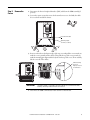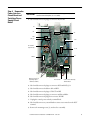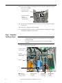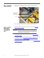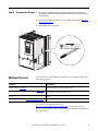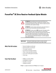
1
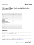
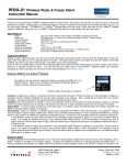
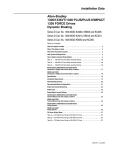
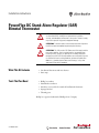
Installation Instructions
PowerFlex DC Stand-Alone Regulator (SAR)
Bimetal Thermostat
ATTENTION: Only qualified personnel familiar with DC drives and
associated machinery should plan or implement the installation,
start-up, and subsequent maintenance of the system. Failure to comply
may result in personal injury and/or equipment damage.
ATTENTION: To avoid an electric shock hazard, ensure that all power to
the SAR has been removed before performing the following.
ATTENTION: This SAR contains ESD (Electrostatic Discharge) sensitive
parts and assemblies. Static control precautions are required when
installing, testing, servicing, or repairing this assembly. Component
damage may result if ESD control procedures are not followed. If you are
not familiar with static control procedures, reference A-B publication
8000-4.5.2, “Guarding Against Electrostatic Damage,” or any other
applicable ESD protection handbook.
What This Kit Includes
• One bimetal thermostat with wire harness
• Static strap
Tools That You Need
•
•
•
•
•
Phillips® screwdriver
Hexalobular screwdriver
Nut driver or wrench for hex stand-offs and bimetal thermostat
Isopropyl alcohol
Thermal grease
Phillips® is a registered trademark of Phillips Screw Company.
23P-IN007A-EN-P
What You Need to Do
The list below is an overview of the steps needed to remove and replace the
bimetal thermostat. See each step for detailed procedures.
1. Remove Power
2. Remove the Covers
3. Remove the Control Circuit Board
4. Remove the Power Interface Circuit Board and Switching Power Supply
Circuit Board
5. Remove the Field Circuit Board
6. Remove the Bimetal Thermostat
7. Install the New Bimental Thermostat and Reassemble the SAR
8. Document the Change
IMPORTANT
The SAR has many different cables, wires, and plugs with different
connections and routing. For ease of reassembly:
• Make note of cable and wire routing between and within the different
circuit boards.
• Label connectors and plugs with the name of the connection and
circuit board from where it was disconnected.
Step 1: Remove Power
ATTENTION: Remove power before making or breaking cable
connections. When you remove or insert a cable connector with power
applied, an electrical arc may occur. An electrical arc can cause
personal injury or property damage by:
• sending an erroneous signal to your system’s field devices, causing
unintended machine motion
• causing an explosion in a hazardous environment
Electrical arcing causes excessive wear to contacts on both the module
and its mating connector. Worn contacts may create electrical resistance.
Remove and lock-out all incoming power to the SAR.
L1
L2
L3
I
O
2
Rockwell Automation Publication 23P-IN007A-EN-P - June 2011
Step 2: Remove the
Covers
1. Disconnect the Device Peripheral Interface (DPI) cable from the HIM assembly (if
present).
2. Loosen the captive screws that secure the bottom front cover to the SAR, then slide
the cover down and off the chassis.
=
Disconnect DPI cable
Tightening torque:
1.5 N•m (13.3.lb•in)
3. Press in on the sides at the bottom edge of the top cover and pull the cover toward you
until the cover is partially off the chassis. Then pull the top of the cover toward you
until the mounting pins align with the keyholes in the top of the cover. Then carefully
lift the cover off of the chassis.
When mounting
pins fits in
keyhole, lift cover
off SAR chassis.
IMPORTANT
The HIM assembly is connected to the control board via a communication cable.
Carefully set the top cover down next to the chassis.
4. Disconnect the HIM communication cable from the control board.
Rockwell Automation Publication 23P-IN007A-EN-P - June 2011
3
Step 3: Remove the
Control Circuit
Board
1. Label and disconnect the ribbon cables at connectors XA, XR, and XFCD.
2. Unplug the terminal block connectors (6) from the control board (if wired).
3. Remove the EMI shield mounting screws (5), and save for reassembly.
4. Remove the EMI shield ground screw (1), and save for reassembly.
Note: The control board remains mounted to the EMI shield.
EMI Shield Mounting
Screws (5)
Tightening torque:
1.0 N•m (8.9 lb•in)
XA
XR
XFCD
Terminal Block
Connectors (6)
EMI Ground Screw (1)
Tightening torque:
1.0 N•m (8.9 lb•in)
5. Carefully lift the EMI shield and control board (to provide clearance from cabling
below), and slide the EMI shield and control board out of the chassis, and carefully set
aside.
4
Rockwell Automation Publication 23P-IN007A-EN-P - June 2011
Step 4: Remove the
Power Interface
Circuit Board and
Switching Power
Supply Circuit
Board
IMPORTANT
The power interface circuit board and the switching power supply circuit
board are removed together, as an assembly.
1. Label and disconnect the plugs at connectors X3 and X4.
X3
X4
XR
XCD
XCD_IO
XPT1
XP1 and XP2
(respectively)
TH-CT
XF
XUVW
Mounting Screws (2)
Tightening torque:
1.0 N•m (8.9 lb•in)
XCT Terminal
Control Power and Relay
Terminal Block
2. Label and disconnect the plugs at connectors XCD and XCD_IO.
3. Label and disconnect the ribbon cable at XPT1.
4. Label and disconnect the plugs at TH-CT and XF.
5. Label and disconnect the plugs at connectors at XP1 and XP2.
6. Label and disconnect the plug from connector XUVW.
7. Unplug the control power and relay terminal block.
8. Label and disconnect any external burden resistor circuit wires from the XCT
terminal.
9. Remove the mounting screws (2), and save for reassembly.
Rockwell Automation Publication 23P-IN007A-EN-P - June 2011
5
10. Remove the cooling vent mounting screws (4) on top of the stand-alone regulator,
and save for reassembly.
Fan plug XV connector
(behind cooling vent)
Cooling Vent Mounting
Screws (4)
Tightening torque:
1.0 N•m (8.9 lb•in)
11. Disconnect the fan plug from the XV connector on the switching power supply
circuit board.
12. Remove the cooling vent and fan assembly.
13. Carefully slide the power interface circuit board and the switching power supply
circuit board assembly out of the chassis.
Step 5: Remove the
Field Circuit Board
IMPORTANT
The screws for the field circuit board are different lengths. Be sure to replace
the correct length screw back to the correct fastener location when reinstalling
the field circuit board.
Also, note the location of the mounting points for the transducer cable for
reassembly.
1. Label and disconnect the plug at X3.
Field Power Terminal
Screws (4, long)
Transducer
Cable Mounting
Screw (1, short)
Stand-off
X3
Note: Tightening
torque for all screws:
2.5 N•m (22.0 lb•in)
6
Dual Diode Module
Bus Screws
(3, medium)
Ribbon Cable
Removed from
Hoop Harness
Rockwell Automation Publication 23P-IN007A-EN-P - June 2011
Field SCR Module
Bus Screws
(3, medium)
2. Remove the ribbon cable from its plastic hoop harness (if needed to make more room
for removing the mounting screws).
3. Remove the mounting screws (4, long) to the field power terminals, and save for
reassembly.
4. Remove the mounting screws (3, medium) from the dual diode module, and save for
reassembly.
5. Remove the mounting screws (3, medium) from the field SCR module, and save for
reassembly.
6. Remove the mounting screw (1, short) for the transducer cable to the glastic
stand-off. Save the transducer cable and mounting screw for reassembly.
7. Remove the stand-off and washer from the heatsink, and save for reassembly.
8. Lift the front edge of the field circuit board up at an angle and carefully pass the
mounting screw wells over the glastic spacer stack, and remove the field circuit board.
IMPORTANT
Lift the Front of
the Field Circuit
Board at an
Angle Until you
can Pull the
Mounting
Screw Wells
Over the Glastic
Spacer Stack.
Rockwell Automation Publication 23P-IN007A-EN-P - June 2011
7
Step 6: Remove the
Bimetal Thermostat
1. Remove the stand-off and washer from the heatsink (if needed for additional
clearance).
Bimetal Thermostat
Tightening Torque:
1.0 N•m (8.9 lb•in)
Stand-off
2. Remove the bimetal thermostat from the heatsink and dispose of properly.
Step 7: Install the
New Bimental
Thermostat and
Reassemble the
SAR
1. Install the new bimetal thermostat in reverse order of removal. See Remove the
Bimetal Thermostat on page 8.
IMPORTANT
Thermal grease must be applied to the bottom of the bimetal thermostat
before securing it to the heatsink. Clean the surface of the heatsink and
the new bimetal thermostat with isopropyl alcohol, then apply a thin coat
of thermal grease to the bimetal thermostat.
2. Install the field circuit board in reverse order of removal. See Remove the Field
Circuit Board on page 6.
3. Install the power interface circuit board and switching power supply circuit board in
reverse order of removal. See Remove the Power Interface Circuit Board and
Switching Power Supply Circuit Board on page 5.
4. Install the control circuit board in reverse order of removal. See Remove the Control
Circuit Board on page 4.
8
Rockwell Automation Publication 23P-IN007A-EN-P - June 2011
Step 8: Document the Change 1. Record the installation of the new bimetal thermostat and date of
installation on the field installed option label on the side of the SAR (as
shown below).
2. Replace the SAR covers in the reverse order of removal. See Remove
the Covers on page 3.
3. Install DPI cable (if present).
Additional Resources
These documents contain additional information concerning related Rockwell
Automation products.
Resource
Description
PowerFlex DC Stand-Alone Regulator and Gate Amplifier User
Manual, publication 23P-UM001
Provides installation instructions and connection and configuration information
for the PowerFlex DC Stand-Alone Regulator (SAR).
PowerFlex Digital DC Drive User Manual, publication 20D-UM001
Provides additional installation, configuration, and programming information for
the PowerFlex DC Stand-Alone Regulator (SAR).
Industrial Automation Wiring and Grounding Guidelines, publication
1770-4.1
Provides general guidelines for installing a Rockwell Automation industrial
system.
Product Certifications website, http://ab.rockwellautomation.com
Provides declarations of conformity, certificates, and other certification details.
You can view or download publications at
http://www.rockwellautomation.com/literature. To order paper copies of
technical documentation, contact your local Rockwell Automation distributor or
sales representative.
Rockwell Automation Publication 23P-IN007A-EN-P - June 2011
9
1S7A79
U.S. Allen-Bradley Drives Technical Support - Tel: (1) 262.512.8176, Fax: (1) 262.512.2222, E-mail: [email protected], Online: www.ab.com/support/abdrives
www.rockwel lautomation.com
Power, Control and Information Solutions Headquarters
Americas: Rockwell Automation, 1201 South Second Street, Milwaukee, WI 53204-2496 USA, Tel: (1) 414.382.2000, Fax: (1) 414.382.4444
Europe/Middle East/Africa: Rockwell Automation NV, Pegasus Park, De Kleetlaan 12a, 1831 Diegem, Belgium, Tel: (32) 2 663 0600, Fax: (32) 2 663 0640
Asia Pacific: Rockwell Automation, Level 14, Core F, Cyberport 3, 100 Cyberport Road, Hong Kong, Tel: (852) 2887 4788, Fax: (852) 2508 1846
Publication 23P-IN007A-EN-P - June 2011
Copyright © 2011 Rockwell Automation, Inc. All rights reserved. Printed in the U.S.A.