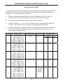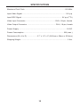
1
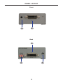
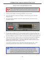
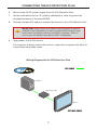
®
DVI Detective
Plus
EXT-DVI-EDIDP
User Manual
www.gefen.com
ASKING FOR ASSISTANCE
Technical Support:
Telephone
(818) 772-9100
(800) 545-6900
Fax(818) 772-9120
Technical Support Hours:
8:00 AM to 5:00 PM Monday through Friday, Pacific Time
Write To:
Gefen LLC
c/o Customer Service
20600 Nordhoff St
Chatsworth, CA 91311
www.gefen.com
[email protected]
Notice
Gefen LLC reserves the right to make changes in the hardware, packaging, and
any accompanying documentation without prior written notice.
DVI Detective Plus is a trademark of Gefen LLC
© 2013 Gefen, LLC. All rights reserved.
All trademarks are the property of their respective owners.
Rev A4
CONTENTS
1Introduction
2
Operation Notes
3Features
4
Panel Layout
5
Panel Descriptions
6
Connecting the DVI Detective Plus
7
8
Wiring Diagram
EDID Programming
8
Using a built-in EDID
9
Writing an EDID using a source device/signal generator
10 Specifications
11Warranty
INTRODUCTION
Congratulations on your purchase of the DVI Detective Plus. Your complete
satisfaction is very important to us.
Gefen
Gefen delivers innovative, progressive computer and electronics add-on solutions
that harness integration, extension, distribution and conversion technologies.
Gefen’s reliable, plug-and-play products supplement cross-platform computer
systems, professional audio/video environments and HDTV systems of all sizes
with hard-working solutions that are easy to implement and simple to operate.
The Gefen DVI Detective Plus
Displays use EDID - Extended Display Identification Data - to communicate to
computers and HDTV sources the array of video resolutions and timings that
they are capable of displaying. In certain situations this data can be lost resulting
in incorrect display settings, or even a complete loss of video. The DVI Detective
Plus solves this problem by ensuring that a correct EDID signal is constantly
available to the DVI source - even if the display is switched to a different
computer. After the simple EDID recording process is completed, the DVI
Detective Plus is placed at the DVI output of the computer’s video card where
it will provide the computer with a constant EDID signal. The Detective Plus is
equipped with DVI ports, but it is also compatible with VGA through the use of
optional adapters.
The DVI Detective Plus provides all the functionality of the DVI Detective N and
adds HDCP pass through and the ability to use one of five pre-programmed
EDID profiles.
How It Works
Connect the DVI Detective Plus connects to the display’s DVI input for initial
programming. Power is applied and the DVI Detective Plus reads and stores
the display’s EDID to the internal memory on the DVI Detective Plus. Connect
the DVI Detective Plus between the source and the display and it will never lose
EDID again.
The DVI Detective Plus includes five built-in selectable generic EDIDs that can
be used for meeting standard display setups. They can be selected by moving
the DIP switches between the different settings.
1
OPERATION NOTES
READ THESE NOTES BEFORE INSTALLING THE
DVI DETECTIVE PLUS
•
Before programming the EDID, make sure all DIP switches are in the OFF
(down) position and the write protect switch is in the E (write enabled)
position.
2
FEATURES
Features
•
Quick and easy recording of EDID information from DVI displays
•
Write custom EDID information using an external source
(e.g. signal generator, etc)
•
Selection of preset EDIDs
•
Supports resolutions up to 1920 x 1200, 2k, and 3840 x 2400 (Dual Link)
•
HDCP-compliant
•
No power required after initial programming
•
Compact unit hides well behind equipment
Package Includes
(1) DVI Detective Plus
(1) 1 ft. DVI cable (M-M)
(1) 5V DC power supply
(1) Quick Start Guide
3
PANEL LAYOUT
Front
1
2
Back
4
3
5
4
PANEL DESCRIPTIONS
1
Programming Button
Press and hold this button to program an EDID. See page 8 for more
information on recording an EDID.
2
DVI In
Connect the included DVI cable from this DVI port to the source device.
3
DIP Switches
Used to select pre-programmed EDIDS.
4
DVI Out
Connect an DVI cable from this DVI port to the display (or other sink device).
5
Write (Enable/Disable) Switch
When switch is set to E (write eneabled), the EDID can be recorded. When
switch is set to D (disabled), the recorded EDID is locked and can not be
earased.
5
CONNECTING THE DVI DETECTIVE PLUS
How to Connect the DVI Detective Plus
STOP: Before proceeding, make sure that the write protect switch is
in the E (write enabled) position and all DIP switches are in the OFF
(down) position. Also, make sure the source device is powered OFF.
1. Power-on the display containing the EDID to be recorded.
2. Use a DVI cable to connect the display to the DVI Out port on the DVI
Detective Plus.
3. Set all four DIP switches in the OFF (down) position, as shown in the
illustration below.
4. Connect the included 5V DC power supply to the DVI Detective Plus. The
power LED will glow bright green if the sink device contains a valid EDID. If
the sink’s EDID is corrupt or invalid, then the power LED will glow bright red.
5. Press and hold the Program button on the front panel of the DVI Detective
Plus until the power indicator begins to rapidly flash bright green, then
release the Program button. The power LED will continue to flash as the
EDID is written to the DVI Detective Plus.
A successful recording will be indicated with a solid green LED. If the
recording process was unsuccessful, the LED will glow bright red.
NOTE: If the DVI Detective Plus does not initiate the recording
sequence, indicated by a flashing green LED, unplug the display
and 5V DC power supply from the unit and repeat steps 2 and 3.
If a solid red LED is indicated after several unsuccessful recording
attempts, it is possible that the EDID from the display is bad. In this
case, see page 8 for instructions on using a built-in EDID.
6
CONNECTING THE DVI DETECTIVE PLUS
6. Remove the 5V DC power supply from the DVI Detective Plus.
7. Set the write switch to the “D” position (disabled) in order to prevent an
accidental erasure of the stored EDID.
8. Use the included DVI cable to connect the source to the DVI Detective Plus.
IMPORTANT: If the source uses HDCP, then DIP switch 4 must be
enabled (in the ON position) in order to enable HDCP pass-through.
In this case, the display must also be HDCP-compliant. Refer to
your source and display manuals for HDCP compatibility.
9. Apply power to the DVI source.
If a computer is being used as the source, restart the computer only after all
connections have been made.
Wiring Diagram for the DVI Detective Plus
DVI CABLE
Computer
DVI Detective Plus
Monitor
EXT-DVI-EDIDP
7
OPERATING THE DVI DETECTIVE PLUS
Using a built-in EDID
The DVI Detective Plus includes five built-in EDIDs for use with several standard
home theater setups with multi-channel audio and standard HD resolutions.
Asterisks (“*”) indicate native resolutions.
1. Make sure that the write switch on the DVI Detective Plus is in the “E”
position and that all DIP switches are in the OFF (down) position.
2. Select the desired EDID from the Resolutions column.
3. Set DIP switches 1 - 3 on the DVI Detective Plus using the DIP Switches
column. DIP switch 4 is not used when programming an EDID.
4. Press and hold the Program button on the front panel of the DVI Detective
Plus until the power indicator begins to rapidly flash bright green, then
release the Program button.
EDID
Resolutions
Refresh Rate
Audio
1
720 x 576p 4:3
720 x 576p 16:9
1280 x 720p 16:9
1920 x 1080p 16:9
*1920 x 1080i 16:9
50 Hz
8 CH PCM
DIP Switches
1
ON
2
3
OFF OFF
2
720 x 576p 4:3
1440 x 480i 16:9
1280 x 720p 16:9
1920 x 1080p 16:9
*1920 x 1080i 16:9
59.94 / 60 Hz 8 CH PCM OFF ON
3
720 x 576p 4:3
720 x 576p 16:9
1280 x 720p 16:9
1920 x 1080p 16:9
*1920 x 1080i 16:9
4
720 x 480 16:9
720 x 576p 16:9
1280 x 720p 16:9
1920 x 1080p 16:9
*1920 x 1080i 16:9
59.94 / 60 Hz 2 CH PCM OFF OFF ON
5
720 x 480p 4:3
1440 x 480p 4:3
720 x 480p 16:9
1440 x 480p 16:9
1280 x 720p 16:9
1920 x 1080i 16:9
*1920 x 1080p 16:9
59.94 / 60 Hz 2 CH PCM ON
8 CH PCM
DTS®
Dolby®
50 Hz
8
2 CH PCM ON
ON
OFF
OFF
OFF ON
OPERATING THE DVI DETECTIVE PLUS
Writing an EDID using a source device/signal generator
The DVI Detective Plus allows a signal generator (or other source device) to write
an EDID to the Detective. This provides additional flexibility when programming
custom timings and refresh rates.
1. Make sure that the write-protect switch on the DVI Detective Plus is in the
“D” (disable write-protect) position and make sure all DIP switches are in the
OFF (down) position.
2. Use an DVI cable to connect the source (generator) device to the DVI In port
on the DVI Detective Plus.
3. Connect the included 5V DC power supply to the DVI Detective Plus.
4. Use the source (generator) device to send the EDID data to the DVI
Detective Plus.
9
SPECIFICATIONS
Maximum Pixel Clock ...............................................................................165 MHz
Input Video Signal..................................................................................... 1.2V p-p
Input DDC Signal ............................................................................... 5V p-p (TTL)
Video Input Connector .......................................................... DVI-I, 29-pin, female
Video Output Connector ........................................................ DVI-I, 19-pin, female
Power Supply .............................................................................................. 5V DC
Power Consumption .............................................................................. 5W (max.)
Dimensions (W x H x D) ................... 2.7” x 1.5” x 2” (68.5mm x 38mm x 50.8mm)
Shipping Weight ............................................................................................ 2 lbs.
10
WARRANTY
Gefen warrants the equipment it manufactures to be free from defects in material
and workmanship.
If equipment fails because of such defects and Gefen is notified within two (2)
years from the date of shipment, Gefen will, at its option, repair or replace the
equipment, provided that the equipment has not been subjected to mechanical,
electrical, or other abuse or modifications. Equipment that fails under conditions
other than those covered will be repaired at the current price of parts and labor in
effect at the time of repair. Such repairs are warranted for ninety (90) days from
the day of reshipment to the Buyer.
This warranty is in lieu of all other warranties expressed or implied, including
without limitation, any implied warranty or merchantability or fitness for any
particular purpose, all of which are expressly disclaimed.
1. Proof of sale may be required in order to claim warranty.
2. Customers outside the US are responsible for shipping charges to and from
Gefen.
3. Copper cables are limited to a 30 day warranty and cables must be in their
original condition.
The information in this manual has been carefully checked and is believed to
be accurate. However, Gefen assumes no responsibility for any inaccuracies
that may be contained in this manual. In no event will Gefen be liable for
direct, indirect, special, incidental, or consequential damages resulting from
any defect or omission in this manual, even if advised of the possibility of such
damages. The technical information contained herein regarding the features and
specifications is subject to change without notice.
For the latest warranty coverage information, refer to the Warranty and Return
Policy under the Support section of the Gefen Web site at www.gefen.com.
PRODUCT REGISTRATION
Please register your product online by visiting the Register Product page
under the Support section of the Gefen Web site.
11
Rev A4
20600 Nordhoff St., Chatsworth CA 91311
1-800-545-6900
818-772-9100
www.gefen.com
Pb
This product uses UL listed or CE compliant power supplies.
fax: 818-772-9120
[email protected]