1
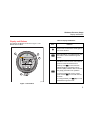
2700G Series Reference Pressure Gauge Users Manual September 2012 © 2012 Fluke Corporation. All rights reserved. Specifications are subject to change without notice. All product names are trademarks of their respective companies. LIMITED WARRANTY AND LIMITATION OF LIABILITY Each Fluke product is warranted to be free from defects in material and workmanship under normal use and service. The warranty period is one year and begins on the date of shipment. Parts, product repairs, and services are warranted for 90 days. This warranty extends only to the original buyer or end-user customer of a Fluke authorized reseller, and does not apply to fuses, disposable batteries, or to any product which, in Fluke's opinion, has been misused, altered, neglected, contaminated, or damaged by accident or abnormal conditions of operation or handling. Fluke warrants that software will operate substantially in accordance with its functional specifications for 90 days and that it has been properly recorded on non-defective media. Fluke does not warrant that software will be error free or operate without interruption. Fluke authorized resellers shall extend this warranty on new and unused products to end-user customers only but have no authority to extend a greater or different warranty on behalf of Fluke. Warranty support is available only if product is purchased through a Fluke authorized sales outlet or Buyer has paid the applicable international price. Fluke reserves the right to invoice Buyer for importation costs of repair/replacement parts when product purchased in one country is submitted for repair in another country. Fluke's warranty obligation is limited, at Fluke's option, to refund of the purchase price, free of charge repair, or replacement of a defective product which is returned to a Fluke authorized service center within the warranty period. To obtain warranty service, contact your nearest Fluke authorized service center to obtain return authorization information, then send the product to that service center, with a description of the difficulty, postage and insurance prepaid (FOB Destination). Fluke assumes no risk for damage in transit. Following warranty repair, the product will be returned to Buyer, transportation prepaid (FOB Destination). If Fluke determines that failure was caused by neglect, misuse, contamination, alteration, accident, or abnormal condition of operation or handling, including overvoltage failures caused by use outside the product’s specified rating, or normal wear and tear of mechanical components, Fluke will provide an estimate of repair costs and obtain authorization before commencing the work. Following repair, the product will be returned to the Buyer transportation prepaid and the Buyer will be billed for the repair and return transportation charges (FOB Shipping Point). THIS WARRANTY IS BUYER'S SOLE AND EXCLUSIVE REMEDY AND IS IN LIEU OF ALL OTHER WARRANTIES, EXPRESS OR IMPLIED, INCLUDING BUT NOT LIMITED TO ANY IMPLIED WARRANTY OF MERCHANTABILITY OR FITNESS FOR A PARTICULAR PURPOSE. FLUKE SHALL NOT BE LIABLE FOR ANY SPECIAL, INDIRECT, INCIDENTAL, OR CONSEQUENTIAL DAMAGES OR LOSSES, INCLUDING LOSS OF DATA, ARISING FROM ANY CAUSE OR THEORY. Since some countries or states do not allow limitation of the term of an implied warranty, or exclusion or limitation of incidental or consequential damages, the limitations and exclusions of this warranty may not apply to every buyer. If any provision of this Warranty is held invalid or unenforceable by a court or other decision-maker of competent jurisdiction, such holding will not affect the validity or enforceability of any other provision. Fluke Europe B.V. Fluke Corporation P.O. Box 1186 P.O. Box 9090 5602 BD Eindhoven Everett, WA 98206-9090 The Netherlands U.S.A. 11/99 Table of Contents Title Page Introduction .................................................................................................................... 1 How to Contact Fluke Calibration ................................................................................... 1 Standard Equipment....................................................................................................... 2 Safety Information .......................................................................................................... 2 Special Conditions for Safe Use ................................................................................ 3 Symbols ..................................................................................................................... 4 Display and Buttons ....................................................................................................... 5 Operation ....................................................................................................................... 6 How to Setup the Product .......................................................................................... 6 Engineering Units ................................................................................................. 6 Set Auto Off .......................................................................................................... 7 Show Battery Voltage ........................................................................................... 7 Display Actual Temperature ................................................................................. 7 Set Damping ......................................................................................................... 7 i 2700G Series Users Manual Set Sample Rate .................................................................................................. 7 Set Tare ............................................................................................................... 7 Function Lock ....................................................................................................... 8 Supervisory Mode ..................................................................................................... 8 Available Pressure Ranges ....................................................................................... 8 How to Set a Custom Engineering Unit or Scale....................................................... 9 Battery Life .................................................................................................................... 9 Maintenance .................................................................................................................. 9 How to Clean the Product ......................................................................................... 9 How to Change the Batteries .................................................................................... 10 Accessories ................................................................................................................... 11 USB Interface Cable ................................................................................................. 11 Power Module ........................................................................................................... 11 Serial Interface Instructions ........................................................................................... 13 Initiating Communication ........................................................................................... 13 List of Commands ..................................................................................................... 13 Parameter Units ............................................................................................................. 14 Error Codes ................................................................................................................... 15 Units Conversion ........................................................................................................... 16 Specifications ................................................................................................................ 18 Accuracy ................................................................................................................... 18 Media Compatibility................................................................................................... 18 Environmental ........................................................................................................... 18 Mechanical Specifications ......................................................................................... 19 Available Pressure Ranges ....................................................................................... 20 ii List of Tables Table 1. 2. 3. Title Page Symbols................................................................................................................................. 4 Display and Buttons .............................................................................................................. 5 Units Conversion ................................................................................................................... 16 iii 2700G Series Users Manual iv List of Figures Figure 1. 2. 3. Title Page The Product ........................................................................................................................... 5 Change the Batteries ............................................................................................................. 10 USB Power Module and Universal Connectors ..................................................................... 12 v 2700G Series Users Manual vi Introduction How to Contact Fluke Calibration The 2700G Series Reference Pressure Gauges (the Product) are high-accuracy digital pressure test gauges. Accurate to 0.02 % FS, the Product can be used as a calibration reference, or in applications where highaccuracy pressure measurement is required. To contact Fluke Calibration, call one of the following telephone numbers: The Product features user-configurable functions that include: • Sampling rate • Tare • Damping • Auto off • Min Max When the Product is configured, you can lock its settings and use password protection to prevent configuration changes. See the “Supervisory Mode” section. • • • • • • • • • Technical Support USA: 1-877-355-3225 Calibration/Repair USA: 1-877-355-3225 Canada: 1-800-36-FLUKE (1-800-363-5853) Europe: +31-40-2675-200 Japan: +81-3-6714-3114 Singapore: +65-6799-5566 China: +86-400-810-3435 Brazil: +55-11-3759-7600 Anywhere in the world: +1-425-446-6110 To see product information and download the latest manual supplements, visit Fluke Calibration’s website at www.flukecal.com. To register your product, visit http://flukecal.com/registerproduct. 1 2700G Series Users Manual Standard Equipment The Product ships with: • Protective Cover (installed) • Three AA Alkaline Batteries (installed) • Safety Information (printed) • Report of Calibration • Manuals CD-ROM with translated Users Manuals • USB Cable • USB Power Adapter • NPT to ¼ BSP Male Adapter • NPT to M20 x 1.5 Male Adapter XWWarning To prevent injury, only assemble and operate high-pressure systems if you know the correct safety procedures. High-pressure liquids and gases are hazardous and the energy from them can be released without warning. To prevent possible electrical shock, fire, or personal injury: • Read all safety Information before you use the Product. • Use the Product only as specified, or the protection supplied by the Product can be compromised. • Do not use the Product around explosive gas, vapor, or in damp or wet environments. • Do not use and disable the Product if it is damaged. • Remove the batteries if the Product is not used for an extended period of time, or if stored in temperatures above 50 °C. If the batteries are not removed, battery leakage can damage the Product. Safety Information A Warning identifies conditions and procedures that are dangerous to the user. A Caution identifies conditions and procedures that can cause damage to the Product or the equipment under test. 2 Reference Pressure Gauge Safety Information • • Replace the batteries when the low battery indicator shows to prevent incorrect measurements. The battery door must be closed and locked before you operate the Product. WCaution To prevent possible damage to Product or to equipment under test: • • The display reads “OL” when the pressure source is above the Product range limit. The pressure source must immediately be removed. Do not apply more than the maximum torque specified. Maximum torque specified is 20 Nm = 15 ft-lb. Special Conditions for Safe Use Misuse If the Product is exposed to overpressure or sudden physical shock (such as being dropped) examine it for damage that can cause a safety issue. If necessary, send the Product for examination to Fluke. Refer to the How to Contact Fluke Calibration section. WWarning To prevent possible fire, or personal injury: • Do not use the Product with flammable substances. • The Product is intended for installation only in locations with protection against the entry of solid unwanted objects or water that can compromise safety. 3 2700G Series Users Manual Symbols Symbols used on the Product and in this manual are in Table 1. Table 1. Symbols Symbol Symbol Meaning W Risk of danger. Important information. See manual. P Conforms to European Union directives. X Hazardous voltage. Risk of electrical shock. ) Conforms to relevant North American Safety Standards. ~ This product complies with the WEEE Directive (2002/96/EC) marking requirements. The affixed label indicates that you must not discard this electrical/electronic product in domestic household waste. Product Category: With reference to the equipment types in the WEEE Directive Annex I, this product is classed as category 9 "Monitoring and Control Instrumentation” product. Do not dispose of this product as unsorted municipal waste. Go to Fluke’s website for recycling information. 4 Meaning Conforms to relevant Australian standards. Reference Pressure Gauge Display and Buttons Display and Buttons Table 2. Display and Buttons The Display and Buttons are shown in Figure 1. The Buttons are in Table 2. 2 Item Push to turn on the Product. Push again to turn off the Product. Zeros the display. In Configure Mode, push the button to move forward through the menus. 3 4 Function MIN MAX records minimum and maximum pressure values and saves them to memory. Push to show maximum (MAX) indication. Push again to show minimum (MIN) indication. After 2 seconds, the gauge goes back to live operation. To clear the MIN MAX memory values, push and hold for 2 seconds until CLr is shown. 1 In Configure Mode, push () to move backward through the menus. gsn001.eps Figure 1. The Product 5 2700G Series Users Manual Operation Table 2. Display and Buttons (cont.) Item Push to go to setup and configuration menus. Push to make a selection. When the Product is not in Configuration mode, push to turn on the backlight. Push again to turn off the backlight. NPT Connector Pressure Display Engineering Units 6 Function Bargraph The subsequent sections tell you how to operate the Product. Push to turn on the Product. The analog bar graph at the bottom of the display shows the applied-pressure level relative to the full range of the gauge. Note If you record a Tare value, the pressure shown is not the actual pressure applied. How to Setup the Product Before you use the product, it is necessary to configure it for your application. Push to go to the Setup menu. Each time is pushed, the display goes to the subsequent function. Push or to change the parameter value. When a parameter is set, push to exit the configuration menu or to move to the next parameter. Engineering Units The Product’s default engineering unit shows psi. To change this, push and to move through the standard engineering units plus one custom unit/scale. When the necessary unit shows, push or . Pressure now shows in the chosen engineering units. See the Specifications section for a list of available Reference Pressure Gauge Operation engineering units. See the Supervisory Mode section for instructions to set up custom units. Set Auto Off Auto Off can be set in 1 minute increments from 1 to 30 minutes or you can turn off the function for continuous Product operation. The Product is configured for 30 minutes. Push and to set the necessary interval. The “off” position is at the low end of the selections, less than 1 minute. Show Battery Voltage Actual battery voltage and a percent-of-life bargraph show the battery charge. No adjustments are made in this parameter. Display Actual Temperature The Product is temperature compensated This parameter shows the temperature measured by the internal sensor. Push or to show degrees F or C. Set Damping Selections are “on” and “off” . Damping smooths readings from pulsating pressure sources. Set Sample Rate This function finds how many times pressure is sampled and the display is updated. Selections are 0.5, 1, 3, and 10 samples/second. Note that 10/second gives the fastest response time. Set Tare Use this function to set a constant offset value that is then subtracted from the measured pressure. For example, if a tare is set at 30 psi, and the measured pressure is 37 psi, 7 psi is shown. A pressure of 27 psi is shown as -3 psi. Push and to set the tare value. The value is in relation to the engineering units and resolution selected for display. Tare value can be set to the maximum range of the gauge. For safety, the bar graph always shows the actual pressure in relation to the full range of the gauge regardless of the tare position. This is done to make sure that with a “0” reading pressure is being applied to the gauge. 7 2700G Series Users Manual Function Lock When set, access to each of the settable parameters above can be turned “off” to prevent unauthorized configuration changes. This is done with password protection in Supervisory Mode. Push to access Supervisory Mode or to go back to normal operation. Supervisory Mode If necessary, each user-configurable parameter can be edited when you receive the Product. Some parameters are locked and must be unlocked to configure them. Use Supervisory mode to do this. When you are in the Configure menu, and FUnC LOCK is shown, it means that there are locked parameters. To disable function lock: 1. Push . 0 PWRD is then shown. 2. The password “101” is required to unlock Supervisory mode. Push to put in the password entry. Hold or down to move faster through the selections by a factor of 10. When you stop the counter, push and again to move forward or backward by a factor of 1. The password is factory set and cannot be changed. 3. Push . From this point each parameter can be locked or unlocked. Push and to select UnLOC or LOC for 8 each parameter. To move to the subsequent parameter, push . You can access, lock, or unlock these functions: • Zero function (enable/disable) • Set pressure units (enable/disable) • Auto shutdown adjustment (enable/disable) • Damping settings (enable/disable) • Sample rate setting (enable/disable) • Tare setting (enable/disable) • Custom engineering units (set scale factor) When a function is locked, it cannot be accessed or changed from its current condition until you go to Supervisory Mode and unlock it. Available Pressure Ranges Available pressure ranges are shown in the Specifications section. Reference Pressure Gauge Battery Life How to Set a Custom Engineering Unit or Scale The last menu selection in Supervisory Mode is SET FACTR. You can set a multiplier factor from 0.001 to 100 to make a custom scale. The set factor is multiplied by the psi measured and the result is shown. Example: 40 psi is the equivalent of 1000 lbs of product in a tank. It is necessary to show the product weight with a 100 psi gauge. If you set a factor of 25, 40 psi pressure shows as 1000 (40 x 25). The engineering unit shown is Cust (custom). Battery Life Battery life is approximately 75 hours of operation with the backlight off. When the battery voltage is low, the lowbattery icon () shows on the top left of the display. To replace the batteries, see the How to Change the Batteries section. Maintenance How to Clean the Product Clean the Product with a soft cloth dampened with water or water and weak soap. WCaution To prevent possible damage to the Product, do not use solvents or abrasive cleansers. WCaution For safe operation and maintenance of the product: • Repair the Product before use if the battery leaks. • Remove batteries to prevent battery leakage and damage to the Product if it is not used for an extended period. • Be sure that the battery polarity is correct to prevent battery leakage. • Have an approved technician repair the Product. 9 2700G Series Users Manual How to Change the Batteries XWWarning To prevent possible electrical shock, fire, or personal injury, have an approved technician repair the Product. To change the batteries, see Figure 2: 1. Pull off the Product cover. 2. Use a Phillips screwdriver to loosen the captive screw on the battery door. 3. Remove the battery door. 4. Replace the three AA batteries. 5. Install the battery door again. 6. Tighten the captive screw on the battery door. 7. Return the Product to its Holster. gsn002.eps Figure 2. Change the Batteries 10 Reference Pressure Gauge Accessories Accessories USB Interface Cable Power Module The Product includes a USB power module. See Figure 3. The Product includes an USB interface cable. The input jack is on the back of the Product. You can use serial communication to configure and calibrate the Product and move measurement data from the Product to a PC. For specifications on the interface, see the Specifications section. 11 2700G Series Users Manual gsn003.eps Figure 3. USB Power Module and Universal Connectors 12 Reference Pressure Gauge Serial Interface Instructions Serial Interface Instructions List of Commands The subsequent sections tell you how to set up the Product for serial communication. Use the subsequent list of commands to communicate with the Gauge: Initiating Communication *CLS Clears the error queue Terminal communication can be setup with terminal communication Software on a PC. The terminal must be set as follows: FAULT? Returns an error code from the error queue *IDN? Identification query. Returns the manufacturer, model number, and firmware revision level of the Calibrator. TARE Tares the offset pressure of the reading on the calibrator TARE? Returns the current tare value PRES_UNIT? Returns the pressure unit for the upper display PRES_UNIT Sets the pressure unit for the display ZERO_MEAS Zeros pressure of the calibrator ZERO_MEAS? Returns the current zero offset value MINMAX_RST Resets the minimum and maximum recorded values • Bits per second: 9600 • Data bits: 8 • Parity: None • Stop bits: 1 • Flow control: None • Local echo on 13 2700G Series Users Manual MIN? Returns the minimum recorded value Parameter Units MAX? Returns the maximum recorded value psi Pressure in pounds per square inch TEMP? Returns temperature in the chosen units bar Pressure in bars CAL_STORE Stores calibration data. mBar Pressure in millibars CUST_MULT? Sets the multiplier for the custom unit type kg/cm2 Pressure in kilograms per centimeter squared STREAM_OFF Turns off streaming data inH2O4C Pressure in inches of water at 4 °C STREAM_ON Turns on streaming data inH2O20C Pressure in inches of water at 20 °C VAL? Returns the measured pressure value in selected units inH2O60F Pressure in inches of water at 60 °F TEMP_UNIT Used to set temperature unit mH2O4C Pressure in meters of water at 4 °C TEMP_UNIT? Returns temperature unit mH2O20C Pressure in meters of water at 20 °C cmH2O4C Pressure in centimeters of water at 4 °C cmH2O0C Pressure in centimeters of water at 20 °C ftH2O4C Pressure in feet of water at 4 °C ftH2O20C Pressure in feet of water at 20 °C 14 The subsequent list of units is used with the Product: Reference Pressure Gauge Error Codes ftH2O60F Pressure in feet of water at 60 °F Error Codes iNHg0C Pressure in inches of mercury at 0 °C The gauge uses the subsequent error codes: mmHg0C Pressure in millimeters of mercury at 0 °C kpal Pressure in kilopascals Far Temperature in Fahrenheit Cel Temperature in Celsius mSW Pressure in meters of SeaWater ftSW Pressure in feet of SeaWater MPA Pressure in MegaPascal torr Pressure in Torr (mmHG0C) 101 A non-numeric entry was received where it should be a numeric entry 102 Too many significant digits entered 103 Invalid units or parameter value received 105 Entry is above the upper limit of the allowable range 106 Entry is below the lower limit of the allowable range 108 A required command parameter was missing 109 An invalid pressure unit was received 117 An unknown command was received 120 The serial input buffer overflowed 121 Too many entries in the command line 122 Pressure module not connected 15 2700G Series Users Manual Units Conversion See Table 3 for units and their conversion factors. Table 3. Units Conversion Unit Name Conversion Factor (from kPa) Conversion Factor (to kPa) psi 0.14503773773 6.894759 bar 0.01 100 MPa 0.001 1000 kgf/cm2 0.010197162130 98.06652 inH2O @ 4 °C 4.014742 0.249082 inH2O @ 20 °C 4.021845 0.248642 inH2O @ 60 °F 4.0185886 0.248844 ftH2O @ 4 °C 0.33456183 2.988984 ftH2O @ 20 °C 0.33515375 2.983705 ftH2O @ 60 °F 0.33488238 2.986123 16 Reference Pressure Gauge Units Conversion Table 3. Units Conversion (cont.) Unit Name Conversion Factor (from kPa) Conversion Factor (to kPa) cmH2O @ 4 °C 10.19744 0.09806383 cmH2O @ 20 °C 10.21549 0.09789056 mH2O @ 4 °C 0.1019744 9.806383 mH2O @ 20 °C 0.1021549 9.789056 kPa 1 1 mbar 10 0.1 inHg @ 0 °C 0.2952998 3.386387 mmHg @ 0 °C 7.500618 0.133322 Torr 7.500618 0.133322 ftSW @ 0 °C 0.325408 3.073062 mSW 0.09918444 10.08222 17 2700G Series Users Manual Specifications Accuracy Positive Pressure ............................................................................ ±0.02 % FS Vacuum .......................................................................................... ±0.05 % FS Temperature Compensation ........................................................... 18 °C to 28 °C (65 °F to 82 °F) to rated accuracy Note: For temperatures from 0 °C to 18 °C and 28 °C to 50 °C, add .003 % FS/°C Media Compatibility 15, 30 psi ........................................................................................ any clean dry non-corrosive gas 100, 300, 500, 1000 psi .................................................................. any liquids or gases compatible with 316 stainless steel Above 1000 psi ............................................................................... any non-flammable, non-toxic, non-explosive, non-oxidizing liquid or gas compatible with 316 stainless steel. Environmental Operating Temperature .................................................................. 0 °C to 50 °C (32 °F to 122 °F) Storage .......................................................................................... -20 °C to +70 °C (-4 °F to +158 °F) Humidity ......................................................................................... 10 % to 90 % RH Non-condensing Altitude............................................................................................ 2000 meters (6561.68 ft.) Pollution Degree ............................................................................ 2 Agency Approvals ........................................................................... P, , ) 18 Reference Pressure Gauge Specifications Mechanical Specifications Dimensions .................................................................................... (11.4 x 12.7) cm, depth = 3.7 cm (4.5 x 5) in, depth = 1.5 in (Without Protective Cover) Pressure Connection ............................................................................. ¼ in NPT Male Housing .................................................................................. Cast ZNAL Display ............................................................................................ 5-1/2 Digits, 16.53 mm (0.65 in) high 20-Segment bar graph, 0 to 100 % Power Battery ................................................................................... three size AA alkaline batteries Battery Life ............................................................................ 75 hours typical without backlight 19 2700G Series Users Manual Available Pressure Ranges Model Number 2030BG100K 2030BG200K 2030BG700K Pressure Range (psi) 15 30 100 300 500 1000 3000 5000 10000 Pressure Range (MPa) 0.1 0.2 0.7 2 3.5 7 20 35 70 Vacuum Range (psi) -15 -15 -12 -12 -12 -12 0 0 0 Vacuum Range (kPa) -100 -100 -80 -80 -80 -80 0 0 0 Burst Pressure (psi) 45 90 1000 2000 2000 10000 10000 10000 15000 Burst Pressure (MPa) 0.3 0.6 7 14 14 70 70 70 100 Proof Pressure (psi) 30 60 200 600 1000 2000 6000 8000 13000 Proof Pressure (MPa) 0.2 0.4 1.4 4 7 14 40 55 90 20 2030BG2M 2030BG3.5M 2030BG7M 2030G20M 2030G35M 2030G70M