1
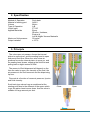
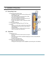
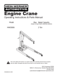
EQUIPMENT
User Manual
BV-303/Suck-back type dispensing valve
Contents
1.
Safety ··············································································································3
1.1 For your safety ····························································································3
1.2 Valve overuse harzard ················································································3
1.3 Others ·········································································································3
2.
Specification ····································································································4
3.
Principle ···········································································································4
4.
Installation & Operation ················································································· 5
4.1
4.2
5.
Connecting lines ······················································································· 5
Operation ···································································································5
Maintenance & Cleaning ·················································································6
5.1
5.2
5.3
5.4
5.5
Storing after use ·························································································6
Check items while operating ····································································· 6
Exploded view ··························································································· 6
Cleaning ···································································································· 7
List of spare parts ······················································································ 7
6.
Trouble shooting ···························································································· 7
7.
Outside view ····································································································8
2
1. Safety
Before installation and using our dispensing valve BV-303, please be carefully
aware of this user manual
1.1 For your safety
If the fluid splashes up to your eyes or skin, it can cause a serious injury.
Handle with extreme care not to be in contact with liquid in case of nozzle
exchange or cleaning.
Make sure that pressure must be released before the nozzle is removed
when you exchange a nozzle.
1.2 Valve Overuse Hazard
If a valve is damaged due to over-pressure, unauthorized alteration of parts,
and overuse, it may cause a danger by exploding or leaking (explosion or
leakage may occur).
Do not make any kind of unauthorized alterations. We are not responsible
for any repairs, after-sales service caused by them.
This valve operates delivery air pressure under 7kgf/cm2. Do not exceed this
operation pressure.
The fluid pressure must not exceed 30kgf/cm2. Or it can cause serious
damages and disorder.
1.3 Others
High pressure material can be leaked if a hose is damaged or worn.
Check a hose for any worn-downs, damages, or swollen before use.
Please change a hose immediately if any malfunction is found.
Prevent leakage from loosened joints by tightening before use.
3
2. Specification
Method of Operation
Material of wetting part
Volume
Type of Operation
Liquid Input
Applied Materials
Maximum fluid pressure
Output variation
Suck-back
A6061
8ℓ/min
A,B
PT 1/8”
Epoxy
Silicone, Urethane,
Engine oil
Low & Middle Viscous Materails
30 kg/cm2
± 2.0 %
3. Principle
The valve open air pressure forces the internal
piston to move down, and the sealing head to open
and permit fluid flow. When the valve close air
pressure forces the internal piston to move up, and
the sealing head closes, stopping the fluid flow and
pulling back a slight amount of fluid.
The amount of fluid dispensed will depend on the
time the valve is open, the viscosity of the fluid, the
air pressure in the fluid reservoir and the dispensing
tip size.
Flow rate is a function of reservoir pressure, tip size
and fluid viscosity.
Suck-back type valves have a sneakhead at the
starting point due to the different of the space which
is get the piston head moves down. And the valve is
suitable for large amount per shot.
Close
Open
4
4. Installation & Operation
4.1 Connecting Lines
1) Connecting Air-pressure lines
- Straightly insert the tube into the air fitting until it
gets installed inside
- Valve open line(A) is connected to the “open”
port on the TAD-200V(controller).
- Valve close line(B) is connected to the “air out”
port on the TAD-200V(controller).
- Pull the tube gently in order to make sure that it
is safe.
2) Connecting Fluid Line
- The inlet of Fluid line(C) fits in PT 1/8” line.
3) Caution
- When you cut the tube, make the severed side a
right angled out and the use of a tube-cutter is
recommended.
- Install the fluid line in oblique with the air line in
order to minimize the intervention.
A
B
C
D
4.2 Operation
1) Preparing to use
- Open the fluid line and valve open air line(A) of
the valve.
- Keep dispensing until the consistent drippings in order to eleminates the
air in the valve.
- And then stop dispensing.
2) Control of the dispensing volume
- Adjust the pressure of fluid inlet.
- Change the nozzle tip(D) to be compatible to preventing from air bubbles.
5
5. Maintenance & Cleaning
5.1 Storing after use
- To avoid the nozzle tip contact air, put an end-cap on the nozzle or keep
a nozzle in the grease.
- Perform the cleaning process(see Chapter 5.4).
5.2 Check items while operating
- Make sure that air supply is in good condition.
- Check other connecting appliances that are properly turned off.
- Be sure that end of nozzle is not clogged with hardened fluid.
5.3 Exploded view
- The user’s arbitrary disassembly is not recommended.
1
2
3
4
5
6
7
8
Fluid outlet tip adapter
Holder cap
Outlet seal
Stop pin
Body casing
O-ring housing
O-ring
Plate seal
BS
A6061
Teflon
SUS303
A6061
Teflon
P4
Teflon
9
10
11
12
13
14
15
Joint nut
Stop nut
O-ring
O-ring
Piston
O-ring
End cap
BS
BS
P8
P18
SUS303
P22
A6061
6
5.4 Cleaning
- Stop providing liquid and release pressure in the fluid chamber.
- Connect the cleaning line to fluid inlet port and add pressure.
- According to chapter 4.2, dispense cleaning liquid instead of fluid.
5.5 List of spare parts
No.
3
4
6
7
Name
Outlet seal
Stop pin
O-ring housing
O-ring P4
No.
8
11
12
14
Name
Plate seal
O-ring P8
O-ring P18
O-ring P22
6. Trouble shooting
Item
No dispensing
Cause
Treatment
Stop pin(4) does not work.
Supply the air into valve on/off line.
The fluid is cured.
Clean the valve.(see chapter 5.4)
The fluid does not supply.
Pressure the fluid reservoir.
Supply the fluid.
Fluid leakage
from nozzle(1)
The controller is turned off.
Turn on the controller.
The needle adaptor(1) is
unfasten.
The lifetime of outlet seal(3) is
end.
The joint nut(9) is unfasten.
Clean the valve.(see chapter 5.4)
And then replace outlet seal(3),
fasten the adapter(1).
Fluid leakage
from Joint nut(9) The lifetime of o-ring housing(6),
o-ring(7) and plate seal(8) is
end.
The stop pin(4) is worn out.
Clean the valve.(see chapter 5.4)
And then replace o-ring housing(6),
o-ring(7) and plate seal(8), fasten the
joint nut(9).
Replace the stop pin(4).
7
7. Outside view
8