1
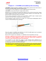
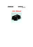
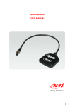
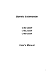
LCU–ONE Analog
User manual
LCU-ONE Analog
User Manual
Release 1.02
INDICE
Chapter 1 – LCU-ONE Description ...............................................................................2
Chapter 2 – LCU-ONE and Lambda probe mounting..................................................3
Chapter 3 – Configuration.............................................................................................4
3.1 – LCU-ONE Analog standard configuration ..................................................4
3.2 – LCU-ONE Analog custom configuration.....................................................7
3.2.1 – Preliminary operation ................................................................................................ 8
3.2.2 – Configuring Lambda controller ................................................................................ 8
3.2.3 – The keyboard............................................................................................................ 11
3.2.4 – Informative panels ................................................................................................... 11
3.2.5 – The analog output graph......................................................................................... 12
Chapter 4 – Online values from Lambda controller..................................................13
Appendix – Part Number and technical drawings ....................................................14
“A” – Part number of LCU-ONE Analog ............................................................14
“B” – Technical drawings ..................................................................................14
www.aim-sportline.com
1
LCU-ONE Analog
User Manual
Release 1.02
0
Chapter 1 – LCU-ONE Description
LCU-ONE is a lambda controller unit for wide band BOSCH LSU 4.9 lambda probe; it
fits petrol (2 and 4 strokes), diesel and methane engines as well as alcohol based fuel
engines. It is intended to check lambda probe proper working as well as to transmit the
Air/fuel ratio values providing MXL/EVO3 with lambda values through the CAN bus.
Lambda value is defined as: LAMBDA= (A/F)/(A Stoichiometric /F Stoichiometric).
where:
A = incoming parts of air;
F = parts of petrol the carburetor injects into the engine;
A Stoichiometric / F Stoichiometric = parts of air needed to burn Stoichiometric F;
Speaking about gasoline, for example, it needs 14,57 parts of air to completely burn a
part of gasoline, obtaining Lambda value = 1 read by the probe.
LCU-ONE controller can detect lambda values in a range of 0.65 to 1.6 (free air).
It is reminded that LAMBDA value lower than 1 means a rich mixture, while
LAMBDA value higher than 1 means a lean mixture.
Wide band Lambda probes need to be heated to work properly and not poisoned with
exhaust gas; LCU-ONE controller precisely manages the probe heater so to keep
temperature value in the optimum working range.
Lambda probe used with LCU-ONE controller becomes very hot (around 700-800
°C, 1292-1472 °F) during its working period, it is thereby necessary AVOIDING:
•
•
touching it.
placing it in contact with flammable stuff or fuel.
Please note:
disrespect of these warnings can cause shocks, burnings or explosions.
www.aim-sportline.com
2
LCU-ONE Analog
User Manual
Release 1.02
1
Chapter 2 – LCU-ONE and Lambda probe mounting
LCU-ONE controller should be installed in a flat location and far from heat sources; it
should be mounted steady using the suited bracket.
The wiring has to be arranged so to avoid it passing near to heat sources.
LCU-ONE is to be powered by the engine master switch.
BOSCH LSU 4.9 Lambda probe should be installed on the vehicle exhaust pipe using a
specific adaptor that comes with the kit and should be welded on the same pipe. The
probe should be sufficiently near to the engine.
Probe working temperature should not exceed 900°C (1652°F) and it should not be
exposed to the free flame coming from the exhaust system.
Probe installation angle should be of at least 10° to avoid liquid condensation stuff to
come in contact with the probe, polluting it.
Once the probe is installed, pay attention not to let the cable pass near to excessive
heat sources (the exhaust pipe for example).
Bosch LSU 4.9 probe auto-calibrates: no calibration is then required by the user.
Solvents or additives should not be used to clean the probe connector. To protect
the probe we would suggest to remove it from the vehicle when cleaning the
vehicle to avoid polluting the probe with detergents.
It is reminded to never switch the vehicle on with Lambda probe installed and not
connected to a correctly working LCU-ONE controller: a probe not heated and exposed
to exhaust gas would be irremediably damaged.
N.B. BOSCH LSU 4.9 Lambda probe has been designed to be used with unleaded
or diesel engine: it can be used with other kind of engines too but its duration
needs to be tested by the user.
www.aim-sportline.com
3
LCU-ONE Analog
User Manual
Release 1.02
2
Chapter 3 – Configuration
To work properly LCU-ONE Analog needs to be configured. The configuration can be
made both using Race Studio 2 and using Lambda Configurator the free software included in the kit - properly designed and developed by AIM to configure this device.
5
3.1 – LCU-ONE Analog standard configuration
Configuration through Race Studio 2 (standard) is possible only if calibration curve
default points – 1.95=0.65 and 4.8=1.6 – have not been modified.
To configure LCU-ONE Analog with Race Studio Configuration follow this procedure:
•
•
•
•
•
•
run the software;
press “AIM system manager” button on the left vertical keyboard;
select the logger LCU-ONE Analog is connected to
activate “Channels” layer
select the analogue channel to set the probe on
double click on “Sensor type” column corresponding to that channel and
select “AIM Lambda LCU-ONE 1.65 – 1.6 Lambda)” option as shown here
below; click out of the cell to confirm the choice.
www.aim-sportline.com
4
LCU-ONE Analog
User Manual
Release 1.02
•
Set the probe configuration panel that appears bottom left of channel layer,
highlighted in the image below.
•
Activate the drop down menu pressing the arrow button circled in the image
above and select the fuel used by the vehicle.
www.aim-sportline.com
5
LCU-ONE Analog
User Manual
Release 1.02
•
In case the fuel used by the vehicle is not included in the database (and only
in case its stoichiometric value is known) press the button “Add custom
value” and the window here below appears.
•
Insert the new value and the test to match. Press “Add new item to the list”
button and then “Save” button.
The fuel is now available in the drop down menu: select it.
•
www.aim-sportline.com
6
LCU-ONE Analog
User Manual
Release 1.02
8
3.2 – LCU-ONE Analog custom configuration
In case calibration curve default points have been modified it is necessary to configure
LCU-ONE Analog using Lambda Caonfigurator software.
Warning: to correctly configure LCU-ONE Analog, please ensure you have
installed a software version 1.00.07 or later.
To configure LCU-ONE Analog run the software. The following window appears.
This is software main window. It is made up of two layers:
•
Lambda controller configurator: it shows analog output graph (central) and
allows the user to configure LCU-ONE Analog, read its configuration and
transmit a new one, restore default Lambda settings, import and export the
configurations and update LCU-ONE Analog firmware.
•
Online values from Lambda controller: it shows LCU-ONE Analog-PC
connection status.
www.aim-sportline.com
7
LCU-ONE Analog
User Manual
Release 1.02
11
3.2.1 – Preliminary operation
Lambda Configurator software, unlike all other AIM software, contains LCU-ONE
Analog firmware. This is why we recommend you to always check our website
www.aim-sportline.com to ensure the software release installed is the latest available. If
not, please download latest release and follow carefully this procedure:
•
•
•
•
•
9
connect LCU-ONE Analog to the PC
read logger firmware version written in the case on the left of the central
graph
press “Upgrade Firmware” button
this message appears:
if the firmware version offered (in the figure the system offers firmware version
25.10) is more recent that the one installed on LCU-ONE Analog (supposing
the one installed is version 25.08), press “Yes” and upgrade the controller
firmware
3.2.2 – Configuring Lambda controller
www.aim-sportline.com
8
LCU-ONE Analog
User Manual
Release 1.02
At the centre of the window are configuration panels.
The first operation to perform is selecting the used fuel in a pop up menu.
In case used fuel is not included in the database and only in case its Stoichiometric
value is known press “Add custom value” button and the window shown below
appears.
Fill in the window with Multiplier value and related legend. Press “Add new item to list
value” and then “Save” button.
Likewise, selecting a multiplier from the left box labelled as “Custom multiplier value list”
and pressing “Remove selected multiplier from the list” button a multiplier will be
removed.
www.aim-sportline.com
9
LCU-ONE Analog
User Manual
Release 1.02
Afterwards it is possible to work on the other parameters.
“Use: Lambda/AFR” these buttons allow the user to decide whether showing Lambda
values or AFR (Stoichiometric) ones. The appearance of the panel below depends on
this choice; here down are the panels showing Lambda values (left) or AFR (right).
The coloured button placed on the left of the cases indicates the colour of this value on
the central graph. In the example the value is showed in light blue.
Once decided which values to show, just fill in the cases.
When all the values have been inserted the configuration has to be transmitted to LCUONE Analog pressing “Transmit lambda configuration” button, placed in the left
keyboard.
The system will show a confirmation message. In case LCU-ONE Analog-PC
connection is not ok the system shows an error message (right figure).
www.aim-sportline.com
10
LCU-ONE Analog
User Manual
Release 1.02
12
3.2.3 – The keyboard
On the left of the window are some buttons:
•
•
•
•
“Restore default lambda settings”: allows the user to restore default settings
on LCU-ONE Analog.
“Transmit lambda configuration”: allows the user to transmit the configuration
to the device
“Read Lambda configuration”: reads the configuration from the connected
device
“UpgradeFirmware”: allows the user to upgrade the firmware of its device.
Bottom central are these buttons:
•
•
“Save Lambda settings”: allows the user to export Lambda configuration
“Load lambda settings”: allows the user to import a Lambda configuration and
transmit it to the device
In the lower part of the window are thrre buttons:
•
•
•
10
“Select language”: allows the user to change the language
“OK”: allows the user to save the set parameters
“Exit”: allows the user to quit discarding changes.
3.2.4 – Informative panels
On top left of the software main window a series of panels shows the characteristics of
the LCU-ONE Analog connected to the PC. These panels are different depending if the
device is connected or not.
Here below you see (left) the panels with the controller connected to the Pc and (right)
the same panels with the controller not connected to the PC.
•
•
•
•
Connected to: PC serial port
Device type: LCU-ONE Analog
(controller has been recognised)
Device ID number: univocal serial
number of the device
Firmware Version: firmware version
installed on the device.
If LCU-ONE Analog is not
correctly connected to the Pc or if
it is not connected at all, the
system shows a “not connected”
message and all information
concerning the controller are set
on N.D. (Not available)
www.aim-sportline.com
11
LCU-ONE Analog
User Manual
Release 1.02
13
3.2.5 – The analog output graph
The “analog output graph” shows output tension values of the controller in
correspondence of the measured Lambda values. Graph colours are customizable.
Pressing “Colour options” button the window shown below appears:
Pressing each button a colour panel will appear showing all the available colours for
that characteristic of the graph. Selecting the desired colour and confirming the choice
graph colours will change.
www.aim-sportline.com
12
LCU-ONE Analog
User Manual
Release 1.02
3
Chapter 4 – Online values from Lambda controller.
This panel shows controller status. The user is only allowed to set Lambda/AFR and
temperature unit of measure for the values shown in this panel.
www.aim-sportline.com
13
LCU-ONE Analog
User Manual
Release 1.02
4
6
Appendix – Part Number and technical drawings
“A” – Part number of LCU-ONE Analog
Complete kit with cable for MyChron3 XGLog
X08LCU04XG
Complete kit with cable for MyChron3 Plus/Gold Auto/Moto
X08LCU04PG
Lambda Probe Bosch LSU 4.9
X05LSU490
7
“B” – Technical drawings
www.aim-sportline.com
14
LCU-ONE Analog
User Manual
Release 1.02
www.aim-sportline.com
15