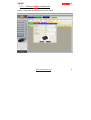
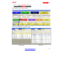
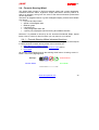
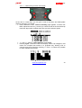
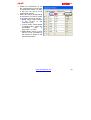
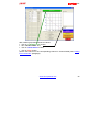
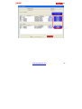
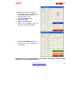
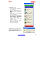
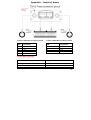
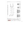
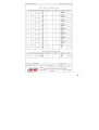
1
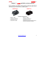
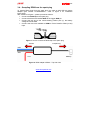
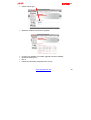
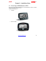
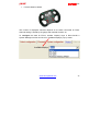
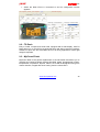
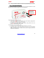
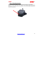
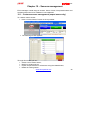
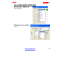
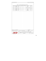
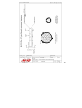
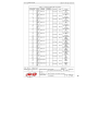
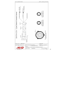
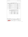
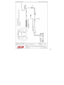
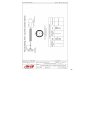
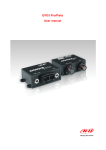
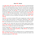
User Manual EVO3 1.00 Dear EVO3 Pista/Pro Owner, Your EVO3 belongs to the latest generation of AIM loggers for car / bike racing and provides you with a powerful, compact, reliable and expandable data acquisition system. Thanks to AIM ECT (Easy Connection Technology), the connection with its wide range of external expansion modules is made in a click. EVO3 allows you to monitor RPM, speed, gear number, lap (split) times and custom sensors. We offer EVO3 in two different versions: Pista and Pro, with 8 (Pista)/16 (Pro) Mb of non volatile Flash internal memory. This memory stores data even when the power is off. EVO3 is supplied with infrared lap transmitter and receiver. Moreover it comes equipped with a powerful bi-axial G-force sensor to create track maps. Expandable, as we said before, EVO3 can be connected to many optional components using the CAN bus: GPS module - to compare your data and your on-track position with the trustworthy precision of the GPS technology. LCU-ONE Lambda Controller – the best solution to keep engine Air/Fuel Ratio under control. USB DataKey – a smart and fast way to save your data . All sampled data can also be visualized connecting EVO3 to one of our hi-tech visors (TG Dash - MyChron3 Dash - Formula Steering wheel), keeping everything under control at a glance. Last but not least EVO3 includes the powerful AIM Race Studio 2 software, that allows you to control and configure your data logger as well as to download and analyze your racing data through the USB port. Thank you for choosing an AIM product! www.aim-sportline.com 1 EVO3 1.00 Chapter 1 – EVO3 available versions and kits EVO3 is available in two different versions and kits. Thanks to its wide range of optional it can fit various situations. The tables below show EVO3 Pista and Pro main characteristics, standard kit and available optional. EVO3 Pista EVO3 Pro Technical characteristics − − − − Memory: 8 Mb Analogue channels: 8 Digital Speed Input: 1 Connectors: 2 AMP − Memory: 16 Mb − Analogue Channels: 12 − Digital Speed Inputs: 4 − Connectors: two (22 pins and 37 pins) Deutsch Professional Autosport www.aim-sportline.com 2 EVO3 1.00 EVO3 Pista EVO3 Pro Standard equipment − EVO3 Pista − Oil temperature sensor − Water temperature sensor − Speed sensor − RPM sensor − IR Lap Tx and Rx1 − USB cable − Race Studio 2 software − CAN/RS232 Cables − Harness − EVO3 Pro − Oil temperature sensor − Water temperature sensor − Speed sensor − RPM Sensor − IR Lap Tx and Rx1 − USB cable − Race Studio 2 software Optional − Split transmitter − Other sensors − Visors: TG Dash, MyChron3 Dash, Formula steering wheel − GPS Module − LCU-ONE Lambda Controller 1 − Split transmitter − Other sensors − Visors: TG Dash, MyChron3 Dash, Formula steering wheel − GPS Module − LCU-ONE Lambda Controller − 37 pins connector harness − 22 pins connector harness IR Lap Tx and Rx means Infrared lap Transmitter and Receiver www.aim-sportline.com 3 EVO3 1.00 Chapter 2 – EVO3 installation and power To install EVO3 Pista/Pro on your vehicle: • Choose a safe location where EVO3 won’t be in contact with oil or fuel sprinklings; • Make sure that the logger is not installed too close to heat sources; • To acquire correct data, please place logger and harnesses far from electromagnetic interference sources like spark plugs and coils; Your EVO3 is equipped with 1 bi-axial internal accelerometer. The recommended installation for this accelerometer, to correctly record in-line (parallel to the vehicle speed) and lateral (perpendicular to the vehicle speed) acceleration, is shown in example 1. You may also install it differently but in this last case Acc_1 and Acc_2 settings need to be changed during configuration, as detailed in examples 2 and 3. www.aim-sportline.com 4 EVO3 1.00 In case of bike installations you can install an optional external gyroscope that would allow you to create track maps. This sensor can only be installed on: • CH_4 to CH_8 on EVO3 Pista • CH_8 to CH_11 on EVO3 Pro. This because these channels only provide the 12 Volt power supply the sensor needs. To power EVO3 Pista/Pro: • Check the power supply voltage: EVO3 needs an external 9/18 VDC power source (the vehicle battery for example). Please don't exceed these limits. • Connect the black GND cable to the negative pole and the red 9/18 VDC cable to the positive one; • To save your battery charge, please connect your EVO3 to the vehicle’s master switch; Please note: EVO3 has a little green led on the front panel. On EVO3 Pista the led is on the top left corner while on EVO3 Pro is bottom central (see Appendix – Technical - draws for further information). This led has a double function: it lights up when EVO3 is powered and shows you the logger status. This means that led status corresponds to logger status: • Led blinking 1 Hz (once a second) Logger waiting to record • Led on (not blinking) Logger recording • Led blinking 3 Hz (three times a second) Logger status not ok www.aim-sportline.com 5 EVO3 1.00 Chapter 3 – How to sample the RPM RPM signal may be sampled in many different ways: • • • • from the ECU: via CAN bus or RS232 line from the ECU: on a square wave signal (from 8 to 50V) from the coil: low voltage RPM input (from 150 to 400V) from the spark plug: converting the RPM waveform sampled from the spark plug into a square waveform 3.1 – Sampling RPM via CAN bus/RS232 line To sample RPM via CAN bus or RS232 line, please refer to Ch. 4. 3.2 – Sampling RPM from the ECU on a square wave signal (EVO3 Pro only) To sample RPM signal from the ECU on a square wave signal (from 8 to 50V), please connect pin 12 of 37 pins Deutsch connector (blue cable) to the ECU RPM output (if present). 3.3 – Sampling RPM from the coil: low voltage RPM input To sample RPM signal from the coil on a low voltage RPM input (150 to 400V), please connect pin 13 (white cable) of 37 pins Deutsch connector to the ECU coil output. www.aim-sportline.com 6 EVO3 1.00 3.4 – Sampling RPM from the spark plug To sample RPM signal from the spark plug you need an AIM ARP-05 custom adapter (part number X10ADRPM000 - refer to figure 2 for installation instructions). With reference to figure 1, please proceed as follows: • Connect the RPM clip to the spark plug. • Connect the black wire labelled GND to the logger GND pin. • Connect the red wire to the vehicle battery positive pole (+): the battery voltage should be 12V. • Connect the blue wire labelled as RPM to EVO3 Pista/Pro RPM (8-15V) input. Figure 1: How to connect the RPM clip to the spark plug To Spark Plug To EVO3 RPM GND RPM clip + 12 V Figure 2: RPM Adapter ARP05 – Top side view www.aim-sportline.com 7 EVO3 1.00 Chapter 4 – How to connect EVO3 to the ECU EVO3 Pista/Pro can sample data out coming from the ECU of your vehicle using a CAN/RS232 cable. To know if your vehicle ECU is supported by EVO3 and for further information about updated ECU-AIM logger connection, please refer to the proper installation manual you can freely download from our website: www.aim-sportline.com. In case you need conversion of non-standard lines (like Subaru K-line) into readable CAN or RS232, please contact us. Please refer always to your ECU user’s manual to check for pins and cable connections. As a general reference, EVO3 systems - ECU connection scheme is reported in the following paragraphs. 4.1 – EVO3 Pista-ECU connection Connection is to be made through the 12 pins AMP connector. Using CAN bus pins connection is: • CAN 1+ pin 4 white cable • CAN 1- pin 3 blue cable Using RS232 line pins connection is • RS232RX pin 6 white cable • RS232TX pin 5 bleu cable www.aim-sportline.com 8 EVO3 1.00 4.2 – EVO3 Pro-ECU connection Connection is to be made through the 22 pins Deutsch connector. Using CAN bus pins connection is: • CAN 1+ pin 20 white cable • CAN 1- pin 21 blue cable Using RX232 line pins connection is: • RS232RX pin 17 white cable • RS232TX pin 18 blue cable www.aim-sportline.com 9 EVO3 1.00 Chapter 5 – Installing Race Studio 2 and configuring EVO3 EVO3 Pista / Pro easily connects to a PC through an USB cable and can be configured only using Race Studio 2 the powerful software properly developed by AIM to configure its instruments and analyze stored data. EVO3 Pista / Pro standard kits include the USB cable and Race Studio 2 CD. Please note: logger configuration is only possible after software and drivers installation. Moreover a periodical check of www.aim-sportline.com website is suggested to know if a new Race Studio 2 software and/or EVO3 Pista/Pro firmware version has been released before proceeding. 5.1 – Installing Race Studio 2 and the USB drivers. Race Studio 2 software has been engineered and developed to guarantee maximum working reliability. Its compatibility has been tested with Microsoft Windows XP™ operating system. Microsoft Vista™ compatibility is actually in progress www.aim-sportline.com 10 EVO3 1.00 5.1.1 – Installing Race Studio 2 under Windows XP Before starting software installation: • ensure that your EVO3 is NOT connected to the Pc USB port. if it is, please unplug it; • check WindowTM “Driver signing option” default setting; click on: Start ¨ Settings ¨ Control Panel ¨ System and select “Hardware” layer; click on “Driver Signing” option and select “Warn – Prompt me each time to choose an action” option; confirm pressing OK button. Close all windows. Once this done, please follow carefully the following instructions. • Close all running applications; • Insert Race Studio 2 CD in your CD/DVD drive and, if “auto play” function is enabled installation will start automatically, otherwise double click on “SETUP” icon. www.aim-sportline.com 11 EVO3 1.00 • Enable “New Release of Race Studio 2” checkbox and press “Next>” button. • This window appears. If you are installing Race Studio 2 for the first time, the system starts USB drivers installation and this window appears. Please disconnect any USB cable from your Pc and click on “Start” button: USB drivers installation starts www.aim-sportline.com 12 EVO3 1.00 Please close all running applications and click on “Start” button. • Press twice “Continue Anyway” button. • Press “Finish” button www.aim-sportline.com 13 EVO3 1.00 • Press “Finish” button Connect EVO3 Pista / Pro to your PC using the USB cable and switch the logger on • Click on “Next” button www.aim-sportline.com 14 EVO3 1.00 • Click on “Continue anyway” button • Click on “Finish” button and run Race Studio 2 software Please note: If you connect your EVO3 to another USB port of the same Pc, the system may ask you again for driver installation. Repeat this USB driver installation procedure. This may occur on each USB port you might want to connect your EVO3 to for the first time. www.aim-sportline.com 15 EVO3 1.00 5.2 – Configuring EVO3 with Race Studio 2 Software To configure EVO3 Pista/ Pro run Race Studio 2 software and click on EVO3 Pro/Pista button on the left vertical toolbar (red circled in the figure below) and then on “New” button on the bottom horizontal toolbar (green button, indicated by a bleu arrow in the figure below). www.aim-sportline.com 16 EVO3 1.00 5.2.1 – Creating EVO3 configurations A New Configuration window appear as shown below: www.aim-sportline.com 17 EVO3 1.00 You have to fill in the grey window as explained below. • • • • • • • Data logger type - select EVO3 Pista or EVO3 Pro ECU manufacturer - select your ECU manufacturer if supported. ECU Model - select your model New configuration name name your configuration Vehicle name - enter your vehicle name Choose Speed, Temperature and Pressure measure units Press “OK” button System Manager window (red circled in the figure below) appears. This window is internal to Race Studio 2 main window and allows you to manage all commands related to EVO3 configuration. www.aim-sportline.com 18 EVO3 1.00 On the top of this window, is a four buttons toolbar. • Transmit – Transmits a configuration to EVO3; • Receive – Detects an unknown configuration and stores it in the configurations database; • CAN Net info – Provides information about devices connected to EVO3 through the CAN bus (ex. GPS Module, Lambda Controller, David); • Set acquisition system time – Sets the logger time according to the connected PC one. Under this toolbar is a 6 layers row that shows: • • • • • • Select configuration Channels System configuration Display Video configuration CAN-Lambda Configurator. We are now going to explain all layers www.aim-sportline.com 19 EVO3 1.00 5.2.2 – Selecting EVO3 configuration Activate “Select configuration” layer. This layer has a 6 buttons top toolbar red circled in the figure below. • • • • • • New - creates a new configuration Delete - deletes an existing configuration Clone - Clones/Copies an existing configuration Import - imports a configuration in your database Export - exports a configuration from this database to use it elsewhere Use Video System - in case a DaVid Slave Expansion system (see related user manual for further information) is connected to EVO3 this buttons enables it and its related layer. Please note: in this case EVO3 configuration is not complete until Video configuration layer is completed. Select a configuration clicking the related row (it becomes highlighted in yellow) www.aim-sportline.com 20 EVO3 1.00 5.2.3 – Setting EVO3 channels With reference to the figure below: Activate “Channels” layer. It allows you setting the channels acquired by EVO3 and its layout depends on EVO3 version. EVO3 Pista EVO3 Pro www.aim-sportline.com 21 EVO3 1.00 Channels layer shows on top from 1 up to 4 speed boxes according to EVO3 version. The box(es) can be enabled/disabled through the Channels table placed below the box(es). To enable a speed channel check the correspondent row in the channel table. The figure below shows EVO3 Pista speed channel checked (red circled and highlighted by a red arrow). The related box is enabled. The figure below shows EVO3 Pro speed channels. Two of them are checked and the related boxes enabled, while the other two aren’t. Once speed channel box, shown below, is enabled, you need to set it: • Enter the wheel circumference of your vehicle • Enter the number of pulses per wheel revolution (that corresponds to the number of magnets installed on the wheel) www.aim-sportline.com 22 EVO3 1.00 Channels table: www.aim-sportline.com 23 EVO3 1.00 With reference to the previous figure, channels Table is divided in 8 columns. Here follows description of each column. • Channel identifier: identifies each channel: RPM, Speed, configurable channels labelled as CH_X, ECU channels if the vehicle ECU is supported. These labels cannot be modified. • Enabled/Disabled: shows which channels are enabled/disabled and allows the user to switch them on/off double clicking on the cell. Please note: RPM, speed and gear channels need to be set through system configuration layer. • Channel name: shows the name of each channel and allows the user to change it double clicking on the cell and inserting the desired name. • Sampling frequency: shows each channel sampling frequency and allows the user to change it double clicking on the cell. Please note: increasing sampling frequency maximum storage time decreases as the memory fills up faster; to check time availability always refer to “available time” box red circled in the previous figure. • Sensor Type: shows which type of sensor is installed on each channel and allows the user to set a sensor on a configurable channel choosing it from a list of pre-defined sensors. It is also possible to set a custom sensor assuming you have previously created it (see custom sensor management paragraph). • Measure Unit: shows the unit of measure set for each channel and allows the user to change it with a double click. • Low scale: show sensor lower bounds and allows the user to change it double clicking on the cell. • High Scale: shows sensor upper bounds and allows the user to change it double clicking on the cell. www.aim-sportline.com 24 EVO3 1.00 As far as analogue channels (labelled as CH_X) are concerned here follows their configuration characteristics. EVO3 Pista CH_1 CH_2 CH_3 CH_4 CH_5 CH_6 CH_7 CH_8 EVO3 Pro User defined User defined User defined User defined User defined User defined User defined Gear potentiometer2 CH_1 CH_2 CH_3 CH_4 CH_5 CH_6 CH_7 CH_8 CH_9 CH_10 CH_11 CH_12 User defined User defined User defined User defined User defined User defined User defined User defined User defined User defined User defined Gear Potentiometer2 With reference to channel 8 of EVO3 Pista and channel 12 of EVO3 Pro, their configuration depends on how gear sensor box is set in System configuration layer. 2 If present. When no gear potentiometer is installed these channels can be used and configured like the previous channels. www.aim-sportline.com 25 EVO3 1.00 Setting “Potentiometer Channel 8/12” or “Calculated with Neutral Signal: Channel 8/12” channel labelled as CH_8/12 switches to Calculated Gear and it is only possible to set Channel name and Sampling frequency. As told before setting “Calculated” “ECU” or “None”, CH_8/12 become a user defined channel and works exactly like channels from CH_1 to CH_7/11. EVO3 has a standard bi-axial accelerometer to sample lateral and longitudinal acceleration labelled as ACC_1 – Lateral accelerometer ACC_2 – Longitudinal accelerometer www.aim-sportline.com 26 EVO3 1.00 5.2.4 – How to set the system configuration Activate “System Configuration” layer: It is possible to set: • RPM ; • Gear sensor; • Lap ; • Reference Speed ; • Output signal (only for EVO3 Pro); www.aim-sportline.com 27 EVO3 1.00 RPM Box: If RPM is sampled from the vehicle ECU, please enable “ECU Signal” and set RPM max value. Multiply factor is in fact disabled. If an RPM sensor is installed and connected to EVO3, please enable “AIM Sensor” and fill in Multiply factor and RPM Max Value. RPM row in channel table is now enabled. RPM Sampled from the vehicle ECU RPM sampled from a custom sensor www.aim-sportline.com 28 EVO3 1.00 Gear sensor Box: EVO3 can detect the engaged gear using an on-board gear sensor, sampling it from the ECU or calculating it using an algorithm based on engine RPM and Speed. Available option are: • None: you do not wish to acquire or see engaged Gear value. Please note: dash connection is required anyway. • Potentiometer Channel 8 (EVO3 Pista) /Channel 12 (EVO3 Pro): your vehicle is equipped with a gear potentiometer installed on channel 8/12. • ECU: you wish to acquire this value form the vehicle ECU (assuming it can transmit it). • Calculated (only with Formula steering wheel and MyChron3 dash connected): you wish to calculate the engaged gear through an algorithm based on RPM and speed. To do that fill in “Highest gear number” box. • Calculated+neutral signal: Channel 8/12: you have a neutral sensor you use to calculate gear and acquire neutral signal. Connect it to pin 20 (analogue input channel 12) of the 37 pins Deutsch connector for EVO3 Pro or to pin 9 (analogue input channel 8) of the 16 pins AMP connector for EVO3 Pista. www.aim-sportline.com 29 EVO3 1.00 Lap Box What is obscuring time? “Obscuring time is a time period during which the optic receiver, after detecting a beacon, is “blind” and ignores beacons signals. This value needs to be correctly set if more than one beacon transmitter is installed on the track. Accepted values are from 3 to 255 seconds. What are lap segments? “Lap segments” is the number of segments you wish to divide your track into, and should coincide with the number of white transmitters installed on the track. Accepted values are from 1 to 6. If you do not wish to capture split times on a track where more than one beacon transmitter is installed, please set obscuring time to a value lower than your track best lap time and higher than the time elapsed between last split and start/finish line. If you wish to capture splits you need to set this parameter value lower than best split time. In case your track is equipped with red transmitters no lap segments filling in is needed: EVO3 Pista/Pro automatically recognizes the transmitters. Lap box – no split is set Lap box – split detection set Reference Speed box: Choose the speed you want to refer to for gear calculation and to display (if dash is connected) www.aim-sportline.com 30 EVO3 1.00 Output signal box (EVO3 Pro only): This feature allows EVO3 Pro to send an output signal to an external system, typically a dashboard or anECU. This output is connected on pin 14 of the 22 pins Deutsch Connector of EVO3 Pro and has the following technical characteristics: • Voltage – Depending on External pull-up voltage • Output duration – about 0,8 seconds (for Lap (-) and Lap (+) only) • Type – it can be “Lap” or “Alarm” type. Available options are: • None: output signal disabled. • Lap(-): when EVO3 Pro receives a lap signal, output signal decreases from External pull-up voltage (idle status) to 0V (lap) for about 0,8 seconds. • Lap(+): when EVO3 Pro receives a lap signal, output signal increases from 0V (idle status) to External pull-up voltage (lap) for about 0,8 seconds. • Shift light: when RPM are over the selected threshold, the output signal increases from 0V (OFF status) to External pull-up voltage (ON status) for the time in which threshold value is exceeded. This feature may be useful if you want to light an alarm led on your dashboard. In Formula Renault applications, for example, “Lap” option enables EVO3 to send a Lap-Beacon signal to vehicles default dashboard. www.aim-sportline.com 31 EVO3 1.00 5.3 – How to transmit the configuration to the logger Once the configuration is set in the software3 it needs to be transmitted via USB to the logger in order to be effective. To do so: • Leave your PC switched on with Race Studio 2 running; • Connect the USB cable to the Pc USB port and plug EVO3 in; use cable labelled as “USB” of your EVO3 harness (Pista and Pro); • Power EVO3; • Go to Race Studio 2 System manager window; • Press “Transmit” button on the top toolbar. 3 And the USB drivers are installed www.aim-sportline.com 32 EVO3 1.00 • This window appears Once the configuration transmitted, the systems informs you about transmission result. www.aim-sportline.com 33 EVO3 1.00 Chapter 6 – How to download and save tests Once a test session is finished, stored data can be downloaded on a Pc using our database management system. EVO3 automatically groups data for a track session as a RUN. A run is made of the laps recorded between 2 pit stops and 2 power on/off. To download data: • Switch on the PC and run Race Studio 2 software; • Connect EVO3 Pista / Pro to the PC USB port through the USB cable: • Switch the logger on; • Click on “Download” button in Race Studio 2 top toolbar; www.aim-sportline.com 34 EVO3 1.00 The following window appears. • • • • • • • • • • Chose folder: allows the user to choose download destination folder. DRK File name: allows the user to name downloaded data. Select all: selects all runs. Deselect all: deselect all runs. Shows runs marked as Hidden: shows/hides runs according with “Hidden” checkbox (highlighted by a red arrows in the figure below) status. Option; see next figure. Clear data logger memory: erases all data without downloading. Download selected runs, then clear memory: downloads data related to a selected track session and erases the memory of EVO3 after download. Download selected: downloads only selected runs. Cancel: exit download without erasing or downloading data. www.aim-sportline.com 35 EVO3 1.00 Pressing “Option” button this window appears: It allows you to group runs in different ways (one file for each run, one file for each date, one file for all runs) as well as choosing how to show your runs after download. www.aim-sportline.com 36 EVO3 1.00 Chapter 7 – EVO3 Memory All EVO3 models are equipped with a non-volatile FLASH internal memory whose dimensions depend on the logger version. This memory is saved even when power is off or disconnected. Memory size: • EVO3 Pista: 8 MB • EVO3 Pro: 16 MB When memory is completely full, EVO3 automatically overwrites oldest data. www.aim-sportline.com 37 EVO3 1.00 Chapter 8 – EVO3 Maintenance EVO3 does not need any special maintenance. Provided that adequate care is taken of logger and components we only suggest to periodically check for software / firmware upgrades. Upgrades are released by AIM and published on www.aim-sportline.com To upgrade software / firmware user should: • connect to www.aim-sportline.com • go to “Download / Technical support” section www.aim-sportline.com 38 EVO3 1.00 • Select vehicle type; • Select the software / firmware to upgrade; • • • • Check if any software or firmware upgrade has been released; Download clicking on it; Run it; Follow the instruction prompted on the screen www.aim-sportline.com 39 EVO3 1.00 Chapter 9 – Installation Notes 9.1 – Connecting an AIM dashboard to EVO3 EVO3 can be connected to various types of AIM dashboards in order to visualize channels and alarms during the race. Available dashboards are • TG Dash • MyChron3 Dash www.aim-sportline.com 40 EVO3 1.00 • Formula Steering Wheel The number of displayed channels depends on the dash connected to EVO3. Channel setting is stored by the gauge and restored at switch on. To configure the dash for EVO3, activate “Display” layer in Race Studio 2 System Manager window and click on “Available Displays” pop up menu. www.aim-sportline.com 41 EVO3 1.00 • Select the Dash EVO3 is connected to and its configuration window appears. 9.2 – TG Dash Easy to install, compact and small sized, equipped with a wide display, AIM TG Dash allows you to view EVO3 acquired lap times and data in real time. Perfectly suitable on sport cars and motorbikes and on all racing applications where light weight is important. 9.3 – MyChron3 Dash MyChron3 Dash is the perfect replacement of the stock dash and allows you to visualize and customize EVO3 channels like RPM, speed, engaged gear number, temperatures, oil pressure, lap time, alarms, etc as well as all signals coming from custom sensors, merged with those coming from the vehicle ECU. www.aim-sportline.com 42 EVO3 1.00 9.4 – Formula Steering Wheel This EVO3 Dash merges an high tech-steering wheel with a smart dashboard. Anodized aluminium frame, ergonomic shape, hand-woven shammy leather as well as an amazing “racing look” are some of the technical features professional drivers appreciate. Thanks to its integrated amber or green backlighted display, all data are available at a glance: • Lap time and lap number • Speed or RPM digital value • RPM bar graph • 5 shift light led • 4 fully configurable alarm led • 4 (two by two) displayed channels among all available channels. Moreover, it is possible to remote up to four functions like Neutral, Radio, Speed limiter, Launch control or other functions you may need on your vehicle. 9.4.1 – Formula Steering Wheel advanced functions Formula Steering Wheel has some advanced functions designed and developed to satisfy all driver’s needs; among all the most innovative are: • Main data driving session review • Predictive lap time (a sub-menu of Control Panel option). • Hour Meter All function are managed through the steering wheel menu. Pressing “menu/<<” button, main menu page appears: Backlight Control Panel Hour Meter Session Mode www.aim-sportline.com 43 EVO3 1.00 9.4.1.1 – Main driving session data review At the end of a track day, you can give a look to lap times and RPM peaks (Session summary). To do that: • Press “Mem/OK” button: session summary page appears. It shows max RPM, Speed and max CH_1 and CH_2 values as well as the three best lap times with lap number, highest and lower rpm and maximum speed. • “>>” and “<<” buttons, switch between stored Tests. • Pressing again “mem/OK” button the display shows Lap Histogram, that means the complete test session in a graphical way, allowing user to compare every lap to best lap. Pressing “>>” and “<<” buttons it is possible to switch between stored laps. www.aim-sportline.com 44 EVO3 1.00 • Pressing “mem/OK” button again Lap Details page is shown. It displays Maximum and Minimum speed and RPM values, custom channel from 1 to 4 values and split times (if sampled). www.aim-sportline.com 45 EVO3 1.00 9.4.1.2 – Session mode Once entered Session mode menu, you can choose between Lap Counter, Timed and Race. • Lap counter: the display shows lap number increasing it each time a lap is finished until your logger is turned off. • Timed: shows the remaining time until the end of the session. To set it insert the number of minutes you are going to race and press OK button. • Race: shows the remaining laps until the end of the session. To set it insert the total number of laps you are going to run and press OK button. www.aim-sportline.com 46 EVO3 1.00 9.4.1.3 – Control panel Once entered Control panel you can choose to set: Hold peak RPM, Split Mode, Predictive, Restart Gear Calib, System Information. • Hold peak RPM: through “mem/ok” button you can set how long the RPM peak marker is shown on display (accepted values are from 5 to 10 seconds) or disable it selecting OFF function. • Split mode: you can choose: o +/- Best: shows the gap between current lap and the best one o Actual: shows actual split time o Accumulative: shows elapsed time from lap counter to last split line. o None: split mode is not active • Predictive (lap time): this function needs to be enabled. Available options are: Disabled: predictive lap time is not active Diff Mode: predicts gap between next lap time and best one Absolute: predicts next lap time • Restart gear calib: This function allows you to restart Gear Calibration procedure directly from your Steering Wheel. For further information, please refer to the related (10.2.1) paragraph www.aim-sportline.com 47 EVO3 1.00 • System information: this function shows your steering wheel firmware version and serial number. In case you need Technical support from AIM, please remember to always communicate your System Information. 9.4.1.4 – Hour Meter This valuable function allows you to view engine running time. Formula steering wheel can record running time of up to four engines. To start running engine time counter: • • • • • press “Menu” button, move to Hour Meter Menu, press “OK” button, select the engine you want to time-count pressing “>>” and “<<” buttons, press “OK” button to confirm To reset engine time counter, once selected the engine: • press twice “OK” button and engine time counter is reset. Please note: engine total running time cannot be reset. www.aim-sportline.com 48 EVO3 1.00 9.5 – How to install and power infrared transmitter and receiver 9.5.1 – The infrared transmitter AIM infrared transmitters are: the lap transmitter and the split transmitter. The split transmitter emits a different signal and EVO3 recognizes it. NOTE: Infrared led light cannot be noticed by human eye even when turned on; The lap transmitter can be powered by • 8 AA batteries (placed in the transmitter case): when battery charge status is low, power led starts blinking each second. • an external 12V power cable: in case battery charge status is low, the power led starts blinking each second. The transmitter has two operating mode: • Low power mode: for track whose width is less than 10 m (30 ft) • High power mode: for track whose width is more than 10 m (30 ft).Please note: 12V external power is needed and both power led lights up when the transmitter is switched on. www.aim-sportline.com 49 EVO3 1.00 To activate High/Low power function • Unscrew the transmitter case on its back • Place the jumper clip, yellow circled in the picture below, − over one of the two connectors for “Low power” mode − over both connectors for “High power” mode; please note: 12V external power is needed. Warning: please be sure of the number of transmitters already placed on the track while placing your one. There may be elsewhere than at start-finish line. The simplest way to take correct lap values is to use the same transmitter(s) for all racers. Through “Obscuring time” setting (see “How to set the system configuration” paragraph) you can ensure that EVO3 reads only your selected transmitter(s). Incorrect “Obscuring time” settings or unknown multiple transmitters can cause EVO3 to record inaccurate or confusing lap times. www.aim-sportline.com 50 EVO3 1.00 9.5.2 – The infrared receiver The infrared receiver needs to “see” the transmitter placed on the trackside. Install it on the vehicle with the receiver’s eye pointed toward the beacon transmitter on the correct side of the vehicle. The red arrow below indicates the receiver’s eye position. www.aim-sportline.com 51 EVO3 1.00 Chapter 10 – Sensors management EVO3 manages a wide range of sensors. Some of them, like potentiometers and accelerometers need to be calibrated / auto-calibrated 10.1 – Custom sensors management (expert users only) To create a custom sensor: • Press “Custom Sensor” button on the top toolbar. • The following window appears. Through this window you can: • Create a new custom sensor; • Modify an existing sensor; • Import / Export a sensor or all sensors using the related button; • Delete an existing sensor. www.aim-sportline.com 52 EVO3 1.00 10.1.1 – How to create a Custom sensor • Click on Type of measure box and select the category the sensor belongs to. • Select the unit of measure corresponding to the sensor to create. www.aim-sportline.com 53 EVO3 1.00 • Enable the checkboxes on the left, corresponding to the number of experimental values you want to use (you can use up to 20 experimental values). • Insert the values corresponding to the sensor you want to create in the three columns on the left. x[mV]: logger output voltage in mV (X-axis of the calibration curve) y: temp./ press. values related to voltage output - values are interpolated using a polynomial – (Y axis); Curve Error: useful to verify that the curve calculated by the software is faithful to the experimental values www.aim-sportline.com 54 EVO3 1.00 After inserting experimental sensor values: • click on “compute curve” button; • fill in “Sensor name” box; • click on “Save Sensor” button • click on “Exit” button. Set the new sensor on the corresponding channel in channel table (see “Setting EVO3 channels” paragraph). www.aim-sportline.com 55 EVO3 1.00 10.2 – How to calibrate / auto-calibrate a sensor Once the configuration has been transmitted to EVO3, sensors installed on the vehicle may need to be calibrated/auto-calibrated and the calibration has to be transmitted to the logger. Sensors to be auto-calibrated are: • Internal biaxial accelerometer; • Gyroscope(if present) ; • Potentiometer distance (if present); Sensors to be calibrated are: • Mid zero potentiometer (if present); • Zero based potentiometer (if present); • Gear sensor (see “How to calibrate a gear sensor” paragraph) To calibrate/autocalibrate sensors: • Press “Calibrate” button on the top menu: • Keep the vehicle as horizontal as possible (if your vehicle is a bike, leave it on the prop stand) and set the sensor to calibrate/auto-calibrate in its 0 position. • Press “Click here to auto-calibrate all sensors in the list” if you’re going to auto-calibrate accelerometer, gyroscope or potentiometer distance. • Press “Calibrate” button corresponding to the sensor you’re going to calibrate if the sensor is a Mid zero potentiometer, Zero based potentiometer or Gear sensor. www.aim-sportline.com 56 EVO3 1.00 www.aim-sportline.com 57 EVO3 1.00 • Follow the instruction prompted by your Pc: calibration status will turn from “Default value/To calibrate” to “Calibrated” • Transmit the configuration to the logger www.aim-sportline.com 58 EVO3 1.00 Here below are shown two calibration window: a zero based potentiometer on the left and a mid zero potentiometer on the right. The Pc prompts itself the proper instruction according to the sensor is being calibrated/auto-calibrated. Please note – the sensor calibration procedure is necessary to acquire correct data. www.aim-sportline.com 59 EVO3 1.00 10.2.1 – How to calibrate a gear sensor (potentiometer) To calibrate the gear sensor: • set “Potentiometer channel 8/12” in “System configuration” layer; • click on “Calibrate” button on Race Studio 2 top toolbar; • click on “Calibrate” button corresponding to Gear sensor. www.aim-sportline.com 60 EVO3 1.00 The window on the right appears: • check the boxes corresponding to available gears (up to 9) • engage neutral gear • press “continue” button • engage first gear • press “continue” button • repeat this procedure until the last gear has been engaged. • Press “end calibration” button • Transmit the final calibration to your EVO3. Please note: to correctly execute this procedure the logger has to be turned ON and correctly connected to PC. www.aim-sportline.com 61 EVO3 1.00 Chapter 11 – “Online” function ”Online” function is used to check that everything works properly. After sensor calibration / auto calibration, we suggest you to enter “Online”. To do so, please: • ensure that EVO3 is connected to the PC and switched on • press “Online” button in Race Studio 2 top toolbar. On line windows opens: www.aim-sportline.com 62 EVO3 1.00 On top it shows: • Logger type: EVO3 Pista/Pro • Firmware version of the logger • Total sampling frequency: it’s the sum of the sampling frequencies of all logger channels. In the centre it shows channels table. www.aim-sportline.com 63 EVO3 1.00 On the right it shows: • “Show ADC counts” button mainly used by AIM staff • “Show mV” button mainly used by AIM staff • Battery: shows the actual battery voltage • Memory: shows memory status (used and available) • Lap marker: checks transmitter / receiver channels. Please place the transmitter in front of the receiver to test this function. • Logger-Pc link: shows USB connection status • Logger configuration: shows logger configuration status. • Exit: exit on line window. Please note: if this warning message appears, check that USB cable is correctly plugged in Pc USB ports and in logger one and try again. www.aim-sportline.com 64 Appendix – technical draws 5 Pins 712 Binder Connector pinout 4 Pins 712 Binder Connector pinout PIN Connection PIN Connection 1 2 3 4 5 CAN 0+ GND + VB CAN 09-15V Ext. battery 1 2 3 4 Magnetical Lap GND +VB Optical Lap Logger State signalling Led Status Logger Status Blinking 1 Hz On (not blinking) Blinking 3 Hz Waiting to record Recording Logger status non ok 65 PIN 1 2 3 4 5 6 7 8 9 10 11 12 “A” 12 pins AMP connector pinout Connection GND 9-15V Ext. Battery CAN 1- (ECU Interface) CAN 1+ (ECU Interface) RS232TX (ECU Interface) RS232RX (ECU Interface) USB DRpm 150-400 coil & sq.wave RPM (>8V) +VB GND +VB Speed PIN 1 2 3 4 5 6 7 8 9 10 11 12 13 14 15 16 “B” 16 pins “AMP” connector pinout Connection + Analog Input 4 V reference Analog GND + Analog Input 3 + Analog Input 2 V reference Analog GND + Analog Input 1 + Analog Input 8 USB D+ Analog GND + Analog Input 7 + Analog Input 6 V reference Analog GND + Analog Input 5 66 67 68 69 70 71 Logger State signalling Led Status Logger Status Blinking 1 Hz On (not blinking) Blinking 3 Hz Waiting to record Recording Logger status not ok 72 37 Pins Deutsch Connector Pinout PIN CONNECTION 1 VB Ext. 2 +Analog Input 1 3 +Analog Input 2 4 Analog GND 5 Analog GND 6 V reference 3 7 V reference 2 8 +Analog Input 3 9 +Analog Input 4 10 +Analog Input 6 11 Analog GND 12 RPM 4-8V 13 RPM in 14 +VB 15 GND 16 +VB 17 +VB 18 GND 19 +Analog Input 11 20 +Analog Input 12 21 V reference 5 22 V reference 1 23 +Analog Input 10 24 V reference 6 25 +Analog Input 9 26 +Analog Input 8 27 Analog GND 28 GND 29 +VB 30 Speed1 31 Analog GND 32 +Analog Input 5 33 +Analog Input 7 34 V reference 4 35 Analog GND 36 Speed 37 Lap in 22 pins Deutsch connector Pinout PIN CONNECTION 1 +VB 2 GND 3 CAN 04 CAN0+ 5 Speed 2 6 Speed 3 7 D+ 8 D9 GND 10 +VB 11 GND 12 GND 13 +VB CAN 14 Ext. Gear Flash 15 Ext. input 1 16 Ext. input 2 17 232 RX 18 232 TX 19 GND 20 CAN 1+ 21 CAN 122 VB ext. 73 74 75 76 77 78 79 80 81 82 83 EVO3 1.00 INDEX Chapter 1 – EVO3 available versions and kits .......................................................2 Chapter 2 – EVO3 installation and power ..............................................................4 Chapter 3 – How to sample the RPM .....................................................................6 3.1 – Sampling RPM via CAN bus/RS232 line.....................................................6 3.2 – Sampling RPM from the ECU on a square wave signal (EVO3 Pro only) ..6 3.3 – Sampling RPM from the coil: low voltage RPM input..................................6 3.4 – Sampling RPM from the spark plug ............................................................7 Chapter 4 – How to connect EVO3 to the ECU......................................................8 4.1 – EVO3 Pista-ECU connection ......................................................................8 4.2 – EVO3 Pro-ECU connection ........................................................................9 Chapter 5 – Installing Race Studio 2 and configuring EVO3 ...............................10 5.1 – Installing Race Studio 2 and the USB drivers. ..........................................10 5.1.1 – Installing Race Studio 2 under Windows XP.................................... 11 5.2 – Configuring EVO3 with Race Studio 2 Software ......................................16 5.2.1 – Creating EVO3 configurations ......................................................... 17 5.2.2 – Selecting EVO3 configuration.......................................................... 20 5.2.3 – Setting EVO3 channels.................................................................... 21 5.2.4 – How to set the system configuration ................................................ 27 5.3 – How to transmit the configuration to the logger ........................................32 Chapter 6 – How to download and save tests ......................................................34 Chapter 7 – EVO3 Memory ..................................................................................37 Chapter 8 – EVO3 Maintenance ..........................................................................38 Chapter 9 – Installation Notes ..............................................................................40 9.1 – Connecting an AIM dashboard to EVO3 ...................................................40 9.2 – TG Dash ....................................................................................................42 9.3 – MyChron3 Dash ........................................................................................42 9.4 – Formula Steering Wheel............................................................................43 9.4.1 – Formula Steering Wheel advanced functions .................................. 43 9.4.1.1 – Main driving session data review............................................. 44 9.4.1.2 – Session mode ........................................................................... 46 9.4.1.3 – Control panel............................................................................. 47 9.4.1.4 – Hour Meter ................................................................................ 48 9.5 – How to install and power infrared transmitter and receiver.......................49 9.5.1 – The infrared transmitter.................................................................... 49 9.5.2 – The infrared receiver ........................................................................ 51 www.aim-sportline.com 84 EVO3 1.00 Chapter 10 – Sensors management.....................................................................52 10.1 – Custom sensors management (expert users only) .................................52 10.1.1 – How to create a Custom sensor..................................................... 53 10.2 – How to calibrate / auto-calibrate a sensor...............................................56 10.2.1 – How to calibrate a gear sensor (potentiometer)............................. 60 Chapter 11 – “Online” function..............................................................................62 Appendix – technical draws ..................................................................................65 INDEX ...................................................................................................................84 www.aim-sportline.com 85