1
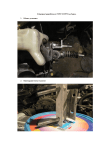
Ford Mustang via OBDII Connection
Ford Mustang – OBDII Connection
ECU Technical Documentation
Release 1.00
INTRODUCTION
AIM has developed special applications for many of the most common ECUs: by special
applications we mean user-friendly systems which allow to easily connect your ECU to our
hi-tech data loggers: user need only to install harness between the logger and the ECU.
Once connected, the logger displays (and/or records, depending on the logger) values like
RPM, engine load, throttle position (TPS), air and water temperatures, battery voltage,
speed, gear, lambda value (air/fuel ratio), analog channels etc…
All AIM loggers include – free of charge – Race Studio 2 software, a powerful tool to
configure the system and analyze recorded data on your PC.
Warning: once the ECU is connected to the logger, it is necessary to set it in the
logger configuration in Race Studio 2 software.
Select Manufacturer “Ford” and Model (depending on own car model – refer to
“Communication protocols” Chapter).
Moreover refer to Race Studio configuration user manual for further information
concerning the loggers configuration.
1
www.aim-sportline.com
Ford Mustang – OBDII Connection
ECU Technical Documentation
Release 1.00
INDEX
Chapter 1 – Car Models ..................................................................................................... 3 Chapter 2 – OBDII CAN Communication Setup ............................................................... 3 Chapter 3 – OBDII position ............................................................................................... 4 Connections to AIM loggers ............................................................................................. 5 Chapter 4 – Ford communication protocols.................................................................... 6 4.3 – Ford Mustang FR500C communication protocol ............................................................................ 6 4.3 – Ford Mustang FR500C MS communication protocol ..................................................................... 7 4.5 – Ford Mustang 2005-2009 communication protocol ........................................................................ 8 4.5 – Ford Mustang 2010 communication protocol ................................................................................. 9 2
www.aim-sportline.com
Ford Mustang – OBDII Connection
ECU Technical Documentation
Release 1.00
0
Chapter 1 – Car Models
Ford ECU is installed on the following car models:
•
•
•
•
Ford Mustang FR500C
Ford Mustang FR500C MS
Ford Mustang 2005/2009 - all models
Ford Mustang 2010 - all models
4
Chapter 2 – OBDII CAN Communication Setup
In all Ford models listed in the previous chapter (ECU communicates On Board
Diagnostic values to AIM loggers through the CAN bus (ISO 15765/4) communication
protocol. It works with EVO4, MXL, EVO3, XGLog, ECU Bridge, using OBDII standard
connector
OBDII standard connector and its pinout are (see below):
Pin
Function
2
Bus positive Line of SAE-J1850
4
Chassis Ground
5
Signal Ground
6
CAN + (ISO 15765-4 and SAE J2234)
7
K Line of ISO 9141-2 and ISO 14230-4
10
Bus negative Line of SAE-J1850
14
CAN – (ISO 15765-4 and SAE-J2234)
15
L line of ISO 9141-2 and ISO 14230-4
16
Battery voltage
3
www.aim-sportline.com
Ford Mustang – OBDII Connection
ECU Technical Documentation
Release 1.00
1
Chapter 3 – OBDII position
OBDII connector position depends on the car model.
The scheme below shows some of the most common OBDII connector position.
Location
Description
Driver’s side, underneath dashboard, in the area under the steering column, +and150 mm (i.e.,+/-6 inches on either side of the steering column).
Driver side, underneath dashboard, between the driver- side door and steering
column area.
Driver side, underneath dashboard, between the steering column area and the center
console (also includes connectors on the driver side but connected to the center
console).
Driver’s side, dashboard instrument/gauge area, between the steering column and
the center console.
Driver’s side, dashboard instrument/gauge area, between the steering column and
the center console
Center console , vertical surface (i.e. near radio and climate controls), left of the
vehicle centreline.
Center console, vertical surface right of the vehicle centreline or on passenger side of
center console.
Center console, horizontal surface (i.e. armrest , and brake area) in front passenger
area
Any location other than locations #1-8 (i.e. rear passenger area, passenger side
glove box, top of dashboard near windshield)
Note: some manufacturers use covers to protect the integrity of the connector. For
further information it is suggested to ask to the dealer where OBDII connector is
situated on the vehicle.
4
www.aim-sportline.com
Ford Mustang – OBDII Connection
ECU Technical Documentation
Release 1.00
2
Connections to AIM loggers
To connect Ford vehicles to AIM loggers:
•
•
connect the cable labelled CAN+ of the logger to pin 6 of the OBDII port
connect the cable labelled CAN- of the logger to pin 14 of the OBDII port
Warning :OBDII is not powered by the vehicle master switch, so if AIM logger is
connected to OBDII for a long time the battery runs down. The communication
works only if the dashboard is switched on.
5
www.aim-sportline.com
Ford Mustang – OBDII Connection
ECU Technical Documentation
Release 1.00
3
Chapter 4 – Ford communication protocols
Depending on the car model there is a different selection to configure the logger (refer to
the appropriate paragraph for more detail about the correct configuration).
5
4.3 – Ford Mustang FR500C communication protocol
To configure Ford Mustang FR500C select the following ECU model “FR500C”
Channels received by AIM loggers connected to Ford Mustang FR500C ECU are:
ID
CHANNEL NAME
FUNCTION
ECU_1
FR500C_RPM
RPM
ECU_2
FR500C_WHEELSPEED
Wheel speed
ECU_3
FR500C_LOAD
Engine load
ECU_4
FR500C_DESIRED_LAMBDA
Desired lambda value
ECU_5
FR500C_WATERTEMP
Engine coolant temperature
ECU_6
FR500C_FUELPRESS
Fuel pressure
ECU_7
FR500C_BATTVOLT
Battery supply
ECU_8
FR500C_TPS
Throttle position sensor
ECU_9
FR500C_LH_LAMBDA
Left bank lambda value
ECU_10
FR500C_AIRTEMP
Intake air temperature
ECU_11
FR500C_EXHAUST_TEMP
Exhaust temperature
ECU_12
FR500C_RH_LAMBDA
Right bank lambda value
ECU_13
FR500C_TRANS_TEMP
Transmission box temperature
ECU_14
FR500C_GEAR
Engaged gear
ECU_15
FR500C_SYNC_LEVEL
Sync. Level
6
www.aim-sportline.com
Ford Mustang – OBDII Connection
ECU Technical Documentation
Release 1.00
6
4.3 – Ford Mustang FR500C MS communication protocol
To configure Ford Mustang FR500C MS select the following ECU model “FR500C_MS”
Channels received by AIM loggers connected to Ford Mustang FR500C MS ECU are:
ID
CHANNEL NAME
FUNCTION
ECU_1
MS_ENG_SPD
RPM
ECU_2
MS_VEH_SPD
Speed
ECU_3
MS_ACC_PDL_POS
Pedal Position Sensor
ECU_4
MS_WHL_SPD_FL
Wheel speed front left
ECU_5
MS_WHL_SPD_FR
Wheel speed front rear
ECU_6
MS_WHL_SPD_RL
Wheel speed rear left
ECU_7
MS_WHL_SPD_RR
Wheel speed rear right
ECU_8
MS_GEAR_PS_ACT
Engaged Gear
ECU_9
MS_ABS_TELTAL
Abs alert
ECU_10
MS_TYRE_SZ
Tyre size
ECU_11
MS_ENG_COOL_T
Engine Coolant Temperature
ECU_12
MS_LOAD
Engine load
ECU_13
MS_DESI_LAMBDA
Lambda
ECU_14
MS_RH_LAMBDA
Lambda
ECU_15
MS_LH_LAMBDA
Lambda
ECU_16
MS_AIR_CH_TEMP
Air Charge Temperature
ECU_17
MS_CPS_SYNC
Chamshaft / Cranckshaft position sensor
ECU_18
MS_FUEL_PRESS
Fuel pressure
ECU_19
MS_BATT_VOLT
Battery Voltage
ECU_20
MS_ZE_FR_TYRE
Tyre
ECU_21
MS_ZE_RR_TYRE
Tyre
ECU_22
MS_MAF_VOLT
Manifold Air Flow Voltage
ECU_23
MS_AIR_FW
Mass Air flow
ECU_24
MS_INJ_PW_Ms
Injection Power
ECU_25
MS_IAC_DC
Idle Air Control (digital value)
7
www.aim-sportline.com
Ford Mustang – OBDII Connection
ECU Technical Documentation
Release 1.00
7
4.5 – Ford Mustang 2005-2009 communication protocol
To configure Ford Mustang 2005-2009 select the following ECU Model ”Mustang 2005/09”
Channels received by AIM loggers connected to Ford Mustang 2005-2009 ECU are:
ID
CHANNEL NAME
FUNCTION
ECU_1
M_RPM
RPM
ECU_2
M_SPEED
Speed
ECU_3
M_PEDAL_POS
Pedal position sensor
ECU_4
M_WH_SPD_FL
Front left wheel speed
ECU_5
M_WH_SPD_FR
Front right wheel speed
ECU_6
M_WH_SPD_RL
Rear left wheel speed
ECU_7
M_WH_SPD_RR
Rear right wheel speed
ECU_8
M_TENGINE
Engine temperature
ECU_9
M_ETC_TELTAL
Engine Traction control tell tale
ECU_10
M_TBO_BST
Turbo boost
ECU_11
M_FUEL_LEV
Filtered fuel level
ECU_12
M_FUEL_I_1
Instant fuel level sensor 1
ECU_13
M_FUEL_I_2
Instant fuel level sensor 2
ECU_14
M_FUEL_AVE
Fuel average level
ECU_15
M_FFLUX
Fuel flux
ECU_16
M_CLCH_SW
Clutch switch
ECU_17
M_TCS_BRK
Traction control brake switch
ECU_18
M_TCS_ENG
Traction control engine switch
ECU_19
M_BRK_SW
Brake switch
ECU_20
M_ABS_TELTAL
ABS tell tale
ECU_21
M_AXLE_RATIO_R
Rear axle ratio
ECU_22
M_MIL_TELTAL
Malfunction indicator lamp
ECU_23
M_FAILSAFE_COOL
Failsafe coolant tell tale
ECU_24
M_GEAR
Engaged gear
ECU_25
M_TYRE
Tyre revs per km
ECU_26
M_SMART_AL
Smart alarm
8
www.aim-sportline.com
Ford Mustang – OBDII Connection
ECU Technical Documentation
Release 1.00
8
4.5 – Ford Mustang 2010 communication protocol
To configure Ford Mustang 2010 select the following ECU Model “Mustang 2010”
Channels received by AIM loggers connected to Ford Mustang 2010 ECU are:
ID
CHANNEL NAME
FUNCTION
ECU_1
F_RPM
RPM
ECU_2
F_SPEED
Speed
ECU_3
F_PEDAL_POS
Pedal position sensor
ECU_4
M_WH_SPD_FL
Front left wheel speed
ECU_5
M_WH_SPD_FR
Front right wheel speed
ECU_6
M_WH_SPD_RL
Rear Left wheel speed
ECU_7
M_WH_SPD_RR
Rear right wheel speed
ECU_8
M_ECT
Traction control
ECU_9
M_ETC_TELTAL
Traction control alarm
ECU_10
M_TURBO_BOOST
Turbo boost
ECU_11
M_FUEL_LVLMEAN
Fuel level
ECU_12
M_FUEL_INST_1
Instantaneous fuel consumption (1)
ECU_13
M_FUEL_INST_2
Instantaneous fuel consumption (2)
ECU_14
M_FUEL_AVERAGE
Average fuel level
ECU_15
M_FUEL_FLOW
Fuel flow
ECU_16
M_CLUTCH_SW
Clutch switch
ECU_17
M_TCS_BRK_EVE
Traction Control Brake Event in progress
ECU_18
M_TCS_ENG_EVE
Engine Control Engine Event in progress
ECU_19
M_BRK_LAMP_SW
Brake switch
ECU_20
M_ABS_TELTAL
ABS Alarm
ECU_21
M_AXLE_RATIO
Axle ration
ECU_22
M_MIL_TELTAL
Malfunction Indicator Light
ECU_23
M_FAILSAFECOOL
Fail safe cooling mode
ECU_24
M_GEAR
Gear
ECU_25
M_TYRE_SIZE
Tyre size
ECU_26
M_SMART_ALARM1
Not available
ECU_27
M_SB_CTRL_TEL
Stability Control Telltale NO/YES
ECU_28
M_SB_CTRL_MTXT
Stability Control Telltale Text Message (code)
ECU_29
M_ABS_EVENT
Not Available
ECU_30
M_ESP_EVENT
Electronic Stability Control event in progress
9
www.aim-sportline.com
Ford Mustang – OBDII Connection
ECU Technical Documentation
Release 1.00
ECU_31
M_TRQ_ACT (Nm)
Torque
ECU_32
M_BRK_WARN_TEL
Brake Warning Telltale ON/OFF
ECU_33
M_VEH_YAW_RATE
Vehicle Yaw Rate
ECU_34
M_VEH_LAT_ACC
Vehicle lateral acceleration
ECU_35
M_STEER_WH_ANG
Steering wheel angle
ECU_36
M_TYRE_RV_MILE
Tyre revolutions for mile
10
www.aim-sportline.com