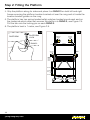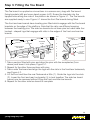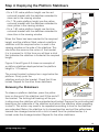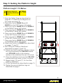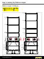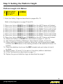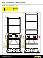
1
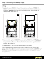
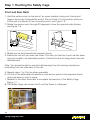
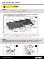
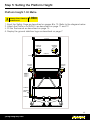
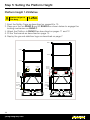
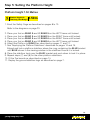
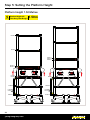
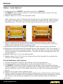
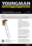
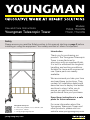
Models:
TTA02, TTA02TB
TTG02, TTG02TB
Use and Care Instructions:
Youngman Telescopic Tower
Safety
Please ensure you read the Safety section in this manual starting on page 3 before
installing or using the equipment. Your safety and that of others is important.
Introduction
Thank you for purchasing our
product. The Youngman Telescopic
Tower is manufactured in
aluminium with an anodised finish.
It is built to withstand the toughest
handling and working conditions.
Suitable for home and commercial
use. Spare parts are readily
available.
We recommend you take your time
and read these instructions. They
contain full installation details and
describe how to deploy the ladder
and how to store it after use to
ensure you get the very best
performance from your purchase.
Keep these instructions in a safe
place for future reference.
Youngman Group Ltd
The Causeway, Maldon, Essex, CM9 4LJ, UK
t: +44 (0)1621 745900
e: [email protected]
youngmangroup.com
For more information about the
Youngman Telescopic Tower and
other products, please visit our
website www.youngmangroup.com
Contents
Introduction1
Safety1
Important Safety Information3
Safety Considerations3
Servicing and Spare Parts3
Main Features4
In the Box5
Equipment and accessories supplied5
Getting Started6
Lock Indicator Buttons6
Castors/Stabilisers6
Deploying the ground stabiliser legs7
Step 1. Erecting the Safety Cage
8
Step 2. Fitting the Platform11
Step 3. Fitting the Toeboards13
Step 4. Deploying the Platform Stabalisers
14
Step 5. Setting the Platform Height
16
Platform height 1.00 metre16
Platform height 1.25 metre18
Platform height 1.50 metre19
Platform height 1.75 metre21
Platform height 2.00 metre24
Collapsing the Tower26
Podium29
Specifications32
Warranty33
Components Identified34
2
youngmangroup.com
Important Safety Information
Warning
For your safety, please read all the safety instructions in this Manual before using
the Youngman Telescopic Tower.
Safety and quality is of paramount importance when manufacturing Youngman
products. All products meet the requirements of the Work at Height Regulations
of 2005.
Important
Read these instructions before installing the Youngman Telescopic Tower.
Important
Install the Youngman Telescopic Tower according the instructions given in this
Manual and on the labels affixed to the equipment.
Safety Considerations
General
• Do not install or use the Youngman Telescopic Tower if damaged in any way.
• Never exceed the maximum load of 150 kg.
• It is recommended that the platform is removed when adjusting the Tower.
• It is recommended that the platform is removed when collapsing the Tower.
• Never release two red buttons at the same time.
• Never place hands or fingers between rungs when collapsing the Tower.
• Always wear a hard hat when erecting or collapsing the Tower.
Cleaning
• Do not use any abrasive or chemical solvents.
• Periodically clean with a soft damp cloth. We recommend occasionally spraying
with a silicon spray.
• The castors should be cleaned using a wet sponge and dried afterwards.
How to Dispose of this Product
When the unit has reached the end of its life, contact your local council regarding
available recycling or disposal options.
Servicing and Spare Parts
A full set of spares are available. Please visit our website for further details for
Servicing and Spare Parts.
3
youngmangroup.com
Main Features
The main features of the Youngman Telescopic Tower are listed below:
• Manufactured in anodised Aluminum (models TTA02 and TTA02TB)
• Manufactured in Fibreglass (models TTG02 and TTG02TB)
• Can be used as a Tower or a Podium
• Has seven working height from 0.33m to 2m
• Five-position stabiliser legs with locking castors
• Can be erected in less than three minutes by a single person thereby
saving down time and man hours
• Folds down for ease of transportation and storage
• Easily transportable in a small van or estate car thereby reducing fuel costs
• Comprises only three parts (main assembly, platform and Toe boards)
4
youngmangroup.com
In the Box
Carefully remove your Tower from the box it arrived in. It is recommended that you
retain this packaging should the item need to be returned under warranty.
Equipments and Accessories Supplied
There are four models of the Tower: TTA02, TTA02TB, TTG02 and TTG02TB. The
illustrations below apply to model TTA02TB where ‘TB’ indicates toe boards are
supplied.
(1) The main assembly in collapsed form (with folded platform)
(2) Toe boards in carrying case (optional with TTA02 and TTG02)
(3) The Instruction and Reference Manual (This publication)
(4) Four lockable castors with adjustable stabilisers
x4
x2
1
2
(x4)
3
4
5
youngmangroup.com
Getting Started
Lock Indicator Buttons
The red and yellow buttons are used to show that the lock
mechanisms are engaged or not when erecting the Tower.
At all height settings, the yellow buttons should always be
in the locked position i.e. guard rails should be in place, see
page 8. At the 2 metre height setting, all
yellow and red buttons should be in their locked position.
INDICATES RUNG 2
ABOVE IS LOCKED
RUNG 3
RUNG 4
INDICATES
RUNG 3 IS NOT LOCKED
THIS POSITION INDICATES
THAT RUNG 4 ABOVE
IS LOCKED
RUNG 5
The locking mechanism of a rung is situated at each end of
the rung immediately below it.
RUNG 6
THIS POSITION
INDICATES RUNG
5 IS UNLOCKED
As a rung is lifted, it automatically locks to the frame when
it is in the correct position. When this happens an audible
‘click’ will be heard. At the same time the red or yellow buttons on the rung
immediately below the one being lifted will move to the locked position, see the
example shown right.
Red buttons
The red buttons on the rungs are used to release the locking mechanism during the
time the Tower is being collapsed. There is a red release-button located near
each end of the rungs labelled RUNG 4, RUNG 5, RUNG 6 and RUNG 7. When a
button is activated by sliding it away from the end of the rung, the locking pin at this
position is retracted which allows the rung immediately above (and any rungs and
or structures above this) to move downwards.
Yellow buttons
The yellow buttons act in the same way as the red buttons and are used during the
time the Tower is being collapsed. The yellow release-buttons are located at
each end of RUNG 2 and RUNG 3. These buttons allow the erected safety cage to
be collapsed.
Castors/Stabalisers
A stabiliser leg is an integral part of each castor. In addition to providing a larger
more stabilized foot print, the stabilisers are used to allow the Tower to be used on
an uneven surfaces.
The stabiliser can be rotated through 270 degrees.
It can be locked in one of five positions set at 45
degree intervals.
The castors and adjustable stabiliser legs are
supplied as a single item.
6
youngmangroup.com
CASTOR SHAFT
ADJUSTER
CASTOR
LOCKING LEVER
CASTOR
STABILISER LEG
STABILISER
FOOT
RELEASE
LEVER
FOOT
Getting Started
Fitting the castors
To fit the castors carry out the following:
1. Carefully lay the fully collapsed main assembly (without platform) in a horizontal
position on the floor or on a bench.
2. Take a castor/stabiliser leg and slide the castor shaft into position on the main
assembly.
3. Push the red button on RUNG 9 away from the castor and push the castor shaft
fully in and rotate until the castor is adjacent to rung 9.
4. Release the button and if necessary rotate it a little further until you hear the
lock-pin click into place, which locks the stabiliser in this position.
PART OF
FRAME
CASTOR
RELEASE
BUTTON ADJUSTER
CASTOR
SHAFT
CASTOR
LOCKING
LEVER
CASTOR
STABILISER FOOT
RELEASE LEVER
FOOT
5. Push down on the stabiliser release lever and lift the stabiliser foot until it is fully
retracted, and then release the lever. This will allow the stabiliser leg to be clear
of the ground when the main assembly is returned to its upright position.
6. Repeat for the other castors and return the Tower to its upright position.
Deploying the Ground Stabiliser Legs
The ground stabiliser legs should be deployed when the Tower has been fully
erected at the required platform height.
1. To move it into place, unlock the castors and push it to the working position.
2. Lock the castors by pushing down on the locking lever with your foot.
3. Slide the red button closest to the ground stabiliser towards the centre of
RUNG 9 and rotate the stabiliser until it is near the required position. Release the
button and rotate a little further either way until you hear the locking mechanism
click in.
4. Deploy a ground stabiliser foot by pressing down on the Adjuster until the foot is
in contact with the surface. Turn the adjuster to tighten it to be in good contact
with the ground. Repeat for the other ground stabilisers as required or allowed.
5. Check that the castors and ground stabiliser legs are secure and locked before
using the Tower.
7
youngmangroup.com
Step 1: Erecting the Safety Cage
This procedure starts from when the Tower is in its fully collapsed arrangement,
with castors fitted as in Figure 1.1.
1.1
Not Locked
RUNG 1
RUNG 2
RUNG 3
RUNG 4
RUNG 5
RUNG 6
RUNG 7
ADJUSTABLE HAND-RAIL
ADJUSTABLE KNEE-RAIL
RUNG 8
LOCKING
GATE
RUNG 9
1. Ensure the castors are unlocked and the wheels are free to rotate.
2. Release the two fabric straps fastened around the legs of the assembly that
hold the two frames together.
3. While keeping the frames together at the back,
1.2
push the front legs slightly apart as shown in
Figure 1.2.
4. Lift and withdraw the folded platform and put it
to one side.
5. Unfold the Tower and straighten the yellow gate
keeping the side frames parallel until the gate
locks. You will hear it click-lock. Check that the
gate is locked.
6. Swing the two side frames so they are each at
90 degrees to the gate and then lock the four
castors by using your foot to push the locking
lever down on all four castors.
8
youngmangroup.com
Step 1: Erecting the Safety Cage
Lifting
1. Hold both ends of RUNG 1 (Figure 1.3) and place one foot on RUNG 9. Lift
RUNG 1 until it locks in place. A click will be heard when it locks and the yellow
buttons on RUNG 2 should then be in the locked position. This has lifted the
hand guardrail, see Figure 1.3.
1.3
RUNG 1
Click
RUNG 2
RUNG 2
RUNG 3
RUNG 4
RUNG 5
RUNG 6
RUNG 7
RUNG 3
RUNG 4
RUNG 5
RUNG 6
RUNG 7
RUNG 8
Locked
RUNG 8
RUNG 9
Locked
Click
Click
LOCKING LOCKING
GATE
GATE
RUNG 9
RUNG 2
Locked
ClickClick
1.4
RUNG 1
RUNG 1
Locked
Locked
RUNG 1
Locked
Click
Click
RUNG 3
RUNG 4
RUNG 5
RUNG 6
RUNG 7
RUNG 2
Locked
Click Click
Locked
Click
RUNG 3
RUNG 4
RUNG 5
RUNG 6
RUNG 7
RUNG 8
RUNG 8
LOCKING LOCKING
GATE
GATE
RUNG 9
RUNG 9
2. Now hold both ends of RUNG 2. Place one foot on RUNG 9 and lift RUNG 2 until
it locks in place, Figure 1.4. This is indicated by the yellow but tons on RUNG 3
being in the locked position. This has lifted the hand and knee guard rails into
position, see Figure 1.4.
3. Repeat steps (1) and (2) on the opposite frame of the Tower.
Note. There is a pair of hand rails and a pair of knee-rails on the left and right
frames of the Tower. The lower part of each pair comprises a side rail, RUNG 1 and
RUNG 2 (fixed), and the upper parts, adjustable hand-rail and adjustable knee-rail
(movable). The latter is the front rail or the rear rail (rear on the left frame, front on
the right frame).
9
youngmangroup.com
Step 1: Erecting the Safety Cage
Front and Rear Rails
1. Hold the yellow cover on the end of an upper handrail using your thumb and
fingers, and push it towards the end of the rail. Hold it in this position while you
lift the end to unfasten it from its anchor point, see Figure 1.5.
2. Rotate the anchor point through 90 degrees to face the opposite side frames,
see Figure 1.6.
1.5
1.6
ROTATE
3. Rotate the rail end towards the opposite frame.
4. Extend the rail until you hear two clicks. This tells you that the 3-part rail has been
securely locked in its extended position. Carefully let the rail hang down from the
attached end.
Note. You should be able to see the ball-bearings from the locking mechanism
protruding from the side walls of the rail.
5. Repeat steps 1 to 4 for the other guardrails.
6. Lift one of the extended rails above its new anchor point on the opposite frame
and push down to lock in place.
7. Repeat for the other three rails to complete the erection of the Safety Cage,
Figure 1.7.
8. The Safety Cage can remain ‘built’ until the Tower is collapsed.
1.6
10
youngmangroup.com
Step 2: Fitting the Platform
3
Rung
Always Place Platform
at this Level
1.00m
2. FITTING THE PLATFORM
3 at this level
Warning
The platform must ALWAYS be mounted on RUNG 3 except
WARNING. The platform must ALWAYS be mounted on RUNG 3 except
when thewhen
Tower
is being used in “PODIUM” mode.
the TELETOWER® is being used in "PODIUM" mode.
Always place Platform
1.00m
RUNG
1.
Fully unfold the platform until it is straight. It will lock straight automatically. Ensure
1. Fullyit has
unfold
theinplatform
untilsee
it is
straight.
locked
this position,
Figure
2.1. It will lock straight automatically.
Ensure it has locked in this position, see Figure 2.1.
2.1
LOCATION
BRACKET
(HIDDEN)
TOE BOARD
FIXING BRACKETS
HOLD SIDE FRAME HERE
WHEN LIFTING PLATFORM
2.1
TRAP DOOR
LOCATION
BRACKET
LOCATION
BRACKETS
TOE BOARD
FIXING BRACKET
HOLD SIDE FRAME HERE
WHEN LIFTING PLATFORM
TOE BOARD
FIXING BRACKET
LOCKING HINGE
RELEASE LEVER
2. The
platform
brackets
fitted
one each
nearcorner
eachon
corner
2. The
platformhas
hasfour
four location
location brackets
fitted
one near
the on the
undersidetotocorrectly
correctly locate
secure
the platform
on the rung
as shown
in shown in
underside
locateand
and
secure
the platform
on the
rung as
Figure
andFigure
Figure 2.2.
3 has
two two
locator
guidesguides
on the inner
faceinner
of theface of
Figure
2.12.1and
2.2.RUNG
RUNG
3 has
locator
on the
the platform correctly, see Figure 2.3.
the rung
rungforforpositioning
positioning
the platform correctly, see Figure 2.3.
WARNING. When lifting the platform, hold the side frames only. Take care
WarningNOT to hold it via the underside panel as there is a trapdoor in the panel.
This the
will platform,
open if youhold
try tothe
support
the weight
of the
platform
at this
When lifting
side frames
only.
Take
care NOT
topoint.
hold it via the
underside panel as there is a trapdoor
try to
2.2 in the panel. This will open if you
2.3
support the weight of the platform at this point.
PLATFORM
PLATFORM
2.2
2.3
PLATFORM
LOCATION
BRACKET
PLATFORM
LOCATION
BRACKET
LOCATION
LOCATION
BRACKET
BRACKET
RUNG
RUNG
3 3
12
youngmangroup.com
RUNG
3
RUNG 3
LOCATION
BRACKET
LOCATION
GUIDE
BRACKET
GUIDE
(1 OF 4)
(1 OF 4)
11
Step 2: Fitting the Platform
3. Grip the platform along its sides and place it on RUNG 3 on both left and right
frames ensuring the platform location brackets sit over the rung and sit inside the
location bracket guides on the rung.
4. The platform has two spring-loaded safety catches located one at each end on
the underside which when set secures the platform to RUNG 3, see Figure 2.4.
Pull the tab onto the locking pin on each RUNG 3.
5. The platform level is 1 metre, see Figure 2.5.
2.4
PLATFORM
PLATFORM
LOCK
HANDRAIL
LOCKED
RUNG 3
RUNG 2
HANDRAIL
LOCKED
KNEERAIL
KNEERAIL
LOCKED
KNEERAIL
LOCKED
TOE BOARD
PLATFORM
RUNG 4
3
RUNG 5
RUNG 6
RUNG 7
RUNG 8
LOCKING
GATE
RUNG 9
12
youngmangroup.com
2.5
HANDRAIL
3. FITTING THE TOE BOARD
The Toe board is supplied as six sections in a canvas carry bag with Toe board fixing
brackets (x8) and cross-head screws (x32). Screw the brackets into the tapped holes
along the side of the platform as shown in Figure 3.1. The Toe boards are supplied
ready to use. Figure 3.1 shows the front Toe boards being fitted.
Step 3: Fitting the Toe Board
The front and rear boards have locating pins fitted which engage with the Toe board
brackets on the edge of the platform. Note that the rails use different spacing between
The Toe board is supplied as six sections
in The
a canvas
carry
with
Toe
board
the locating pins.
side toe boards
do not bag
have pins
but each
have
four hooked shaped lugs that engage with slots in the edges of the front and rear toe boards.
fixing brackets (x8) and cross-head
screws (x32). Screw the brackets into the
3.1
tapped holes along the side of the platform as
shown in Figure 3.1. The Toe boards
TOE BOARD
FIXING BRACKET
are supplied
ready
to use. Figure 3.1 shows the front Toe boards being
fitted.
3. FITTING
THE TOE
BOARD
TOE BOARD
PLATFORM
FITTED
The Toe board is supplied as six sections in a canvas carry bag with Toe board fixing
FRONT OR
REAR
The(x8)
front
and rearscrews
boards
havethelocating
pins
fitted
which
engage with the Toe board
brackets
and cross-head
(x32). Screw
brackets into
the tapped
holes
TOE BOARD
along the side of the platform as shown in Figure 3.1. The Toe boards are supplied
brackets
on
the
edge
of
the
platform.
Note
that
the
rails
use
different spacing
ready to use. Figure 3.1 shows the front Toe boards being fitted.
SLOPING
between the locating pins. The side toe boards do not have pins but eachSURFACE
have four
(TOP)
of CLOSE
the UPfront
and rear toe
OF
The front and rear boards have locating pins fitted which engage with the Toe board
hooked
- shaped
lugs Note
thatthat
engage
with
slots
in the
edges
brackets
on the edge
of the platform.
the rails use
different
spacing
between
TOE BOARD
the locating pins. The side toe boards do not have pins but each have four hooked
FIXING-BRACKET
boards.
shaped lugs that engage with slots in the edges of the front and rear toe boards.
1.
TOE BOARD
FIXING BRACKET
PLATFORM
2.
FRONT OR REAR
TOE BOARD
3.
3.1
3.2
Take a side Toe board and align the
lugs with the slots in the front/rear
toe boards, see Figure 3.2.
SLOPING
5. Repeat
the other side toe board
Take
a section
fitted with pins
and with
REAR for the
1. Take
a section
fitted
pins with the
3.2pins and
toalign
complete.
TOE
BOARD
align the pins with the receptacles
(fromabove)
above) and
lowerlower
it into place,
and
it into place, Figure
3.1.
14
Figure 3.1.
2.
Repeat
for the
other three
3. Take
a side
Toesections
board
with pins.
4.
SIDE
TOE BOARD
2
1 3
FRONT
TOE BOARD
receptacles (from
2. Repeat for the other three sections with pins.
and align the lugs with the slots in the front/rear toeboards,
see Figure 3.2.
Take a side Toe board and align the
4. Lift
front
and
then the rear Toeboards a little (1). Guide the lugs into the slots
lugs
with the
the slots
in the
front/rear
toe boards,
see Figure
3.2.front and rear toe boards (3) to lock together. The side toe board
(2). Lower
the
SIDE
TOE BOARD
Lift the
front and
then the
Toe
cannot
now
berear
removed
without lifting the frontFRONT
and rear toe boards.
LOCATING
boards a little (1). Guide the lugs
TOE BOARD
5.
Repeat
for
the
other
side
toe
board
to
complete.
PINS
into the slots (2). Lower the front and
1 3
rear toe boards (3) to lock together.
The side toe board cannot now be
removed without lifting the front and
rear toe boards.
5.
3.2
with pins.
1.
3.
REAR
TOE BOARD
TOE BOARD
Repeat
FITTED for the other three sections
Lift the frontSURFACE
and then the rear Toe
boards a little
(1). Guide the lugs
(TOP)
into the slots (2). Lower the front and
CLOSE UP OF rear toe boards (3) to lock together.
TOE BOARD The side toe board cannot now be
BRACKET removed without lifting the front and
rear toe boards.
4.
TOE BOARD
FIXING BRACKET
Take a section fitted with pins
3.1and
align the pins with the receptacles
(from above) and lower it into place,
Figure 3.1.
TOE BOARD
BRACKET
2
Repeat for the other side toe board
to complete.
14
13
youngmangroup.com
LOC
PI
Step 4: Deploying the Platform Stabilisers
The platform is equipped with four platform stabilisers (braces) which are stowed
on the underside of the platform, see Figure 4.1.
Warning
The platform stabilisers MUST be deployed when the platform working height is at
or greater than 1.50 metres.
4.1
PUSH DOWN TO
RELEASE THE
LOCK
EXTENSION POSITIONS
PULL LEVER TO
RELEASE STABILISER
LOCKING BALL
MECHANISM
PLATFORM
STABILISER
STOWED
PLATFORM STABILISER
STOWAGE BRACKET
PLATFORM
Press the release button at the far end of the stabiliser and pull back on the yellow
lever to release it from the stowage bracket. The stabilisers are hinged centrally on
the platform and when deployed anchor to brackets on the inner face of RUNGS 5,
6 & 7.
The stabilisers are telescopic in construction and adjustable to three different
lengths to suit the three platform heights that require platform stabilisers to be used.
The free end has a spring self-locking slot, see Figure 4.2.
4.2
There is a spring-loaded ball locking mechanism which holds the stabiliser at any
of the three preset extensions. The stabiliser has a viewing window in its side that
lets you easily adjust it to the correct length using a colour coded system. The
brackets are also coloured, see Figure 4.3.
14
youngmangroup.com
Step 4: Deploying the Platform Stabilisers
• For a 2.00 metre platform height use the red
coloured bracket with the stabiliser extended to
show red in the viewing window.
• For 1.75 metre platform height use the yellow
coloured bracket with the stabiliser extended to
show yellow in the viewing window.
• For a 1.50 metre platform height use the blue
coloured bracket with the stabiliser extended to
show blue in the viewing window.
When the Tower has been erected to the required
height, and the platform fitted, extend a platform
stabiliser until the required colour is seen in the
viewing window on the side of the stabiliser. This
should be the same as the colour of the bracket
it is to connect to. At this time you will hear a click
that indicates the stabiliser is locked at the required
length.
4.3
2 METRE
PLATFORM
HEIGHT
1.75 METRE
PLATFORM
HEIGHT
1.50 METRE
PLATFORM
HEIGHT
STABILIZER
BRACKETS
4.4
Figure 4.4 and Figure 4.5 shows an example of
a platform stabiliser deployed when the platform
height is 1.75 metres.
The correct bracket is always two rungs below the
platform. Firmly push the
stabiliser end onto the bracket. Check that it has
locked. Repeat for the other three stabilisers.
Releasing the Stabalisers
4.5
HOOK ONTO THE BRACKET
ON THE RUNG WHEN AT
THE REQUIRED LENGTH
HINGED
VIEWING WINDOW
DEPRESS AND EXTEND
To release a platform stabiliser, press the yellow
UNTIL THE REQUIRED
COLOUR IS DISPLAYED
lever on the end of the stabiliser and lift the end off
IN THE WINDOW
the bracket. The locking ball bearing will be protruding since the stabiliser will be extended and locked. Depress the protruding ball
bearing on the underside of the stabiliser and retract the stabiliser when preparing
to stow it. This action may need to be repeated according to how far the stabiliser
was extended. Return the stabiliser to its stowed position and pull the yellow lever
towards the stowage bracket until a click is heard from the pivoted end as it is
locked under the stowage bracket. Repeat for the other stabilisers.
15
youngmangroup.com
Step 5: Setting the Platform Height
Decide upon the platform height you require. This is important since the next stage
varies according to the required platform height.
Warning
Although it is possible to erect the Tower with the platform in situ, it is strongly
recommended that the platform is ALWAYS fitted when the Tower is at the required
height.
Warning
The platform must ALWAYS be removed prior to lowering the Tower.
Warning
When you wish to change from one platform height to another, you are
recommended to remove the platform, lower the Tower until the platform height is
at 1.00 metre and then follow the procedure to erect it to the height required.
3
Rung
Always Place Platform
at this Level
1.00m
• For a platform height of
• For a platform height of
• For a platform height of
• For a platform height of
• For a platform height of
16
youngmangroup.com
1.00 metre, follow the procedure on page 17.
1.25 metre, follow the procedure on page 18.
1.50 metre, follow the procedure on page 19.
1.75 metre, follow the procedure on page 21.
2.00 metre, follow the procedure on page 23.
Step 5: Setting the Platform Height
Platform Height 1.00 Metre
3
Rung
1.00m
Always Place Platform
at this Level
1. Erect the Safety Cage as described on pages 8 to 10. Refer to the diagram below.
2. Attach the Platform to RUNG 3 as described on page 11 and 12.
3. Fit the Toe boards as described on page 13.
4. Deploy the ground stabiliser legs as described on page 7.
HANDRAIL
HANDRAIL
LOCKED
RUNG 2
HANDRAIL
LOCKED
KNEERAIL
KNEERAIL
LOCKED
KNEERAIL
LOCKED
TOE BOARD
PLATFORM
RUNG 4
3
RUNG 5
RUNG 6
RUNG 7
RUNG 8
LOCKING
GATE
RUNG 9
17
youngmangroup.com
Step 5: Setting the Platform Height
Platform Height 1.25 Metres
6
Rung
Platform Height Lift
This Rung
1.25m
1. Erect the Safety Cage as described on pages 8 to 10.
2. Place your foot on RUNG 9 and lift RUNG 6 as shown below to engage the
locking mechanism on RUNG 7.
3. Attach the Platform to RUNG 3 as described on pages 11 and 12.
4. Fit the Toe boards as described on page 13.
5. Deploy the ground-stabiliser legs as described on page 7.
RUNG 1
RUNG 1
RUNG 2
RUNG 2
LOCKED
LOCKED
RUNG 3
RUNG 4
RUNG 5
RUNG 6
RUNG 3
RUNG 4
RUNG 5
RUNG 6
RUNG 7
RUNG 8
‘Click’
RUNG 8
LOCKING
GATE
LOCKING
GATE
RUNG 9
RUNG 9
18
youngmangroup.com
LOCKED
RUNG 7
LOCKED
‘Click’
Step 5: Setting the Platform Height
Platform Height 1.50 Metres
5
Rung
Platform Height Lift
This Rung Then Rung 6
1.50m
1. Erect the Safety Cage as described on pages 8 to 10.
Refer to the diagrams on page 20.
2. Place your foot on RUNG 9 and lift RUNG 5 on the LEFT frame until locked.
3. Place your foot on RUNG 9 and lift RUNG 5 on the RIGHT frame until locked.
4. Place your foot on RUNG 9 and lift RUNG 6 on the RIGHT frame until locked.
5. Place your foot on RUNG 9 and lift RUNG 6 on the LEFT frame until locked.
6. Attach the Platform to RUNG 3 as described on pages 11 and 12.
7. See ‘Deploying the Platform Stabilisers’ described on pages 14 and 15.
Extend and lock a platform stabiliser above the rung containing the BLUE bracket
until BLUE shows in the viewing window in the stabiliser. Ensure it is locked.
8. Place the stabiliser hook over the BLUE bracket and push down to lock it in place.
9. Repeat steps (7) and (8) for the other platform stabilisers.
10. Fit the Toe boards as described on page 13.
11. Deploy the ground-stabiliser legs as described on page 7.
19
youngmangroup.com
Step 5: Setting the Platform Height
Platform Height 1.50 Metres
5
Rung
Platform Height Lift
This Rung Then Rung 6
1.50m
RUNG 1
RUNG 2
RUNG 3
RUNG 4
RUNG 5
RUNG 3
RUNG 4
LIFT RUNG 5
LOCKED
RUNG 6
RUNG 7
LIFT RUNG 6
LOCKED
LOCKED
RUNG 7
‘Click’
‘Click’
‘Click’
RUNG 8
RUNG 8
LOCKING
GATE
LOCKING
GATE
RUNG 9
RUNG 9
20
youngmangroup.com
LOCKED
‘Click’
Step 5: Setting the Platform Height
Platform Height 1.75 Metres
4
Rung
Platform Height Lift
This Rung Then Rungs
5&6
1.75m
1. Erect the Safety Cage as described on
page 8 to 10. Refer to the diagrams on
this page and page 22.
2. Place your foot on RUNG 9 and lift
RUNG 4 on the LEFT frame until locked.
3. Place your foot on RUNG 9 and lift RUNG 4
on the RIGHT frame until locked.
4. Place your foot on RUNG 9 and lift RUNG 5
on the RIGHT frame until locked.
5. Place your foot on RUNG 9 and lift RUNG 5
on the LEFT frame until locked.
6. Place your foot on RUNG 9 and lift RUNG 6
on the LEFT frame until locked.
7. Place your foot on RUNG 9 and lift RUNG 6
on the RIGHT frame until locked.
8. Attach the Platform to RUNG 3 as described
on pages 11 and 12.
9. See ‘Fitting the Platform Stabilisers’
described on pages 14 and 15.
10. Extend and lock a platform stabiliser above
the rung containing the YELLOW bracket
until YELLOW shows in the viewing
window in the stabiliser. Ensure it is locked.
11. Place the stabiliser hook over the YELLOW
bracket and push down to lock it in place.
12. Repeat steps (10) and (11) for the other
platform stabilisers.
13. Fit the Toe boards as described on page 13.
14. Deploy the ground stabiliser legs as
described on page 7.
R
RUNG 1
R
RUNG 2
R
R
RUNG 3
LIFT RUNG 4
LOCKED
RUNG 5
RUNG 6
RUNG 7
LOCKED
R
R
‘Click’
‘Click’
RUNG 8
RUNG
LOCKING
GATE
LOCKIN
GATE
RUNG 9
RUNG 9
21
youngmangroup.com
Step 5: Setting the Platform Height
Platform Height 1.75 Metres
4
Rung
Platform Height Lift
This Rung Then Rungs
5&6
1.75m
RUNG 1
RUNG 1
RUNG 2
RUNG 2
RUNG 3
RUNG 4
RUNG 3
RUNG 4
RUNG 5
LIFT RUNG 5
LOCKED
RUNG 6
RUNG 7
‘Click’
LIFT RUNG 6
LOCKED
‘Click’
RUNG 8
RUNG 8
LOCKING
GATE
LOCKING
GATE
RUNG 9
RUNG 9
22
youngmangroup.com
LOCKED
RUNG 7
‘Click’
LOCKED
‘Click’
Step 5: Setting the Platform Height
Platform Height 2.00 Metres
7
Rung
Platform Height
Extend Rungs
3, 4, 5 & 6
2.00m
1. Erect the Safety Cage as described on pages 8 to 10.
Refer to the diagrams on page 24 and 25.
2. Place your foot on RUNG 9 and lift RUNG 3 on the LEFT frame until locked.
3. Place your foot on RUNG 9 and lift RUNG 3 on the RIGHT frame until locked.
4. Place your foot on RUNG 9 and lift RUNG 4 on the RIGHT frame until locked.
5. Place your foot on RUNG 9 and lift RUNG 4 on the LEFT frame until locked.
6. Place your foot on RUNG 9 and lift RUNG 5 on the LEFT frame until locked.
7. Place your foot on RUNG 9 and lift RUNG 5 on the RIGHT frame until locked.
8. Place your foot on RUNG 9 and lift RUNG 6 on the RIGHT frame until locked.
9. Place your foot on RUNG 9 and lift RUNG 6 on the LEFT frame until locked.
10. Attach the Platform to RUNG 3 as described on pages 11 and 12.
11. See ‘Fitting the Platform Stabilisers’ described on pages 14 and 15.
12. Extend and lock a platform stabiliser above the rung containing the RED
bracket until RED shows in the viewing window in the stabiliser. Ensure it is
locked.
13. Place the stabiliser hook over the RED bracket and push down to lock it
in place.
14. Repeat steps (12) and (13) for each of the other platform stabilisers.
15. Fit the Toe boards as described on page 13.
16. Deploy the ground stabiliser legs as described on page 7.
23
youngmangroup.com
Step 5: Setting
the Platform
Height
PLATFORM
HEIGHT
2.00 METRES
7
RUNG
Platform Height
2.00m
Extend rungs 3, 4, 5 and 6
Platform Height 2.00 Metres
7
Rung
2.00m
Platform Height
Extend Rungs
3, 4, 5 & 6
R
RUNG 1
RUNG 1
R
RUNG 2
RUNG 2
RU
RUNG 3
R
LIFT RUNG 3
LOCKED
RUNG 4
RUNG 5
RUNG 6
RUNG 7
‘Click’
LIFT RUNG 4
LOCKED
LOCKED
RUNG 5
RUNG 6
RUNG 7
‘Click’
‘Click’
LOCKED
R
R
‘Click’
RUNG 8
RUNG 8
RUNG
LOCKING
GATE
LOCKING
GATE
LOCKIN
GATE
RUNG 9
RUNG 9
RUNG
24
youngmangroup.com
25
Step 5: Setting the Platform Height
Platform Height 2.00 Metres
7
Rung
Platform Height
Extend Rungs
3, 4, 5 & 6
2.00m
RUNG 1
RUNG 1
RUNG 2
RUNG 2
RUNG 3
RUNG 3
RUNG 4
RUNG 4
RUNG 5
LIFT RUNG 5
LOCKED
RUNG 6
RUNG 7
‘Click’
RUNG 8
LOCKING
GATE
RUNG 9
LIFT RUNG 6
LOCKED
LOCKED
RUNG 7
‘Click’
‘Click’
LOCKED
‘Click’
RUNG 8
LOCKING
GATE
RUNG 9
25
youngmangroup.com
Collapsing the Tower
Warning
The platform must ALWAYS be removed prior to collapsing the Tower.
1. Remove any tools or other items that are on the platform.
2. Remove the Toe board from the platform.
3. Unfasten the four Platform Stabilisers and stow under the platform as described
on page 15.
4. Unfasten the two spring-catches that hold the platform to RUNG 3.
5. Carefully lift the Platform off each RUNG 3 and take the Platform to a safe place
away from the Tower.
Warning
Always begin collapsing Tower assembly by starting from RUNG 7.
Remember
The red and yellow buttons operate as follows:
• The buttons on RUNG 7 release the locking mechanism for RUNG 6 which allows
RUNG 6 and all above to move down .
• The buttons on RUNG 6 release the locking mechanism for RUNG 5 which allows
RUNG 5 and all above to move down.
• The buttons on RUNG 5 release the locking mechanism for RUNG 4 which allows
RUNG 4 and all above to move down.
• The buttons on RUNG 4 release the locking mechanism for RUNG 3 which allows
RUNG 3 and all above to move down.
• The buttons on RUNG 3 release the locking mechanism for RUNG 2 which allows
RUNG 2 and all above to move down.
• The buttons on RUNG 2 release the locking mechanism for RUNG 1 which allows
RUNG 1 to move down.
26
youngmangroup.com
Collapsing the Tower
ARNING. NEVER release the two buttons on a rung at the same time.
Warning
ARNING.
NEVER
hand
fingers
rungs
NEVER
releaseplace
the twoyour
buttons
on aor
rung
at the on
same
time. that are being
wered onto another rung, or on the rung you are lowering to.
Warning
NEVERRUNG
place
hand or
fingers
on rungs
thatis
are
being
onto
another
wing procedure
is2 your
for when
the
platform
height
set
at 2lowered
metres.
Not
all of
rung,
or
on
the
rung
you
are
lowering
to.
ing steps will apply to other platform heights.
n theThe
leftfollowing
frame) procedure is for when the platform height is set at 2 metres. Not all of
the following steps will apply to other platform heights.
one hand hold the stile above RUNG 6 on the left frame prepare to take the
Stepand
1 (On
left frame)
ht of this
allthe
above,
see Figure 6.1.
(a) With one hand hold the stile above RUNG 6 on the left frame prepare to take the
UNG 7, push
button
theFigure
centre
of RUNG 7 and then release the
weightone
of this
and alltowards
above, see
6.1.
n. (b) On RUNG
RUNG3 7, push one button towards the centre of RUNG 7 and then release
the button.
still holding
the stile above RUNG 6, push the button on the other end of
(c) While still holding the stile above RUNG 6, push the button on the other end of
G 7 towards the centre and then release the button and carefully lower
7 towards the centre and then release the button and carefully lower
G 6 ontoRUNG
RUNG
7.
RUNG 6 onto RUNG 7.
(d)
1 (a)
to right
(c) onframe.
the right frame.
at Step Repeat
1 (a)
toStep
(c)
the
RUNG
4 on
6.1
6.1
RUNG 5
STILE
LEFT HAND
GRIP AND SUPPORT
ALL ABOVE
LOWER RUNG 6
(WITH ALL ABOVE )
RUNG 6
RUNG 7
1
2
RUNG 8
RIGHT THUMB
PUSH BUTTONS
TOWARDS CENTRE
LOCKING
epeat as
above for rung 5), but release the buttons on RUNG 6.
GATE
youngmangroup.com
27
Collapsing the Tower
Step 2 (Repeat as above for rung 5), but release the buttons on RUNG 6.
Step 3 (Repeat as above for rung 4), but release the buttons on RUNG 5.
Step 4 (Repeat as above rung 3), but release the buttons on RUNG 4.
Step 5 To collapse the Safety Cage, reverse the procedure given on pages 8 to 10
that describes erecting the Safety Cage.
With the Safety Cage collapsed:
Step 6 (Repeat as above for rung 2), but release buttons on RUNG 3.
Step 7 (On the right frame)
(a) With one hand hold RUNG 1 on the left frame prepare to take the weight of this.
(b) On RUNG 2, push one button towards the centre of RUNG 2 and then release
the button.
(c) While still holding RUNG 1, push the button on the other end of RUNG 2
towards the centre and then release the button and carefully lower RUNG 1
onto RUNG 2.
(d) Repeat Step 7 (a) to (c) on the left frame.
28
youngmangroup.com
Podium
The Podium platform can be set at two heights, 61 cm and 33 cm as shown in the
Figure 7.1 and Figure 7.2 on page 30.
Setting up the Podium
This procedure starts from when the Tower is in its fully collapsed
arrangement, with castors fitted.
1. Ensure the castors are unlocked and the wheels are free to turn.
2. Unfasten the two fabric straps fastened around the legs of the frame assembly
that hold the equipment together and separate the side frames a little at the front.
3. Lift and withdraw the folded platform and put it to one side.
4. Unfold the frame assembly and straighten the yellow gate until the gate locks. You
will hear it click-lock. Check that the gate is locked.
5. Swing the two side frames so they are each at 90 degrees to the yellow gate and
then lock the two castors on the left frame only using your foot to operate the
locking levers on the two castors.
6. Now move the front of the right hand frame slightly outwards. This helps in placing
the platform location brackets on either RUNG 8 or RUNG 9 according to the
podium height required.
7. Fully unfold the platform until it is straight. It will lock straight automatically. Ensure
it has locked in this position. The platform has four location brackets fitted one
near each corner on the underside that fit over the rung to hold the platform in
position. The platform can be fitted on either RUNG 9 (for 33cm platform height),
or RUNG 8 (for 61 cm platform height) depending on the height required.
Warning
When lifting the platform, take care NOT to hold it via the underside panel as there is
a trapdoor in the panel. This will open if you try to support the weight of the platform
at this point.
8. Support the platform and place the left-hand end on to the required rung on the
left hand frame. Now hold the opposite end of the platform pull the right hand
frame towards the platform and lower the platform onto RUNG 8 or RUNG 9
according to the platform height you have chosen. Ensure the location brackets
are sitting correctly on the chosen rung.
See OPTION 1 Figure 7.1 or OPTION 2 Figure 7.2 on the next page which shows
the appearance when erected.
29
youngmangroup.com
Podium
Option 1 and Option 2
1. Hold both ends of RUNG 1 and place one foot on RUNG 9.
2. Lift RUNG 1 until it locks in place. A click will be heard when it locks. This has
lifted the hand guardrail.
3. Repeat steps (1) to (2) on the opposite frame.
Note. There are a pair of hand rails and knee rails on the left and right frames of
the Tower. The lower part of each pair comprises a fixed side rail, and an upper
adjustable part. The front rail is on the right side and the rear rail on the left.
7.1
7.2
4. Hold the yellow cover on the end of the left knee rail using your thumb and
fingers, and push it towards its end of the rail. Hold it in this position while you
lift the end to unfasten it from its anchor point.
5. Rotate the anchor point through 90 degrees to face the opposite side frame.
6. Rotate the rail end towards the opposite frame. See Figures 1.5 & 1.6 on page 10.
7. Extend the rail until you hear two clicks. This tells you that the 3-part rail has been
securely locked in its extended position. Carefully let the rail hang down and rest
on the platform.
8. Repeat steps (4) to (7) for the left handrail.
9. Repeat steps (4) to (7) for the front knee rail and front handrail to complete the
erection of the safety cage.
Ground Stabilisers (both options)
1. Unlock the castors and push the Podium to its working position.
2. Lock the castors by pushing down on the locking lever with your foot.
3. On RUNG 9, slide the red button towards the centre of the rung and rotate the
stabiliser leg until it is near the required position. Release the button and rotate the
ground stabiliser a little further either way until you hear the locking mechanism
click in.
4. Repeat for the other three stabiliser legs.
5. Deploy a stabiliser leg by depressing its release lever until the base of the leg is in
contact with the surface. Turn the adjuster to tighten and where necessary to raise
the Podium to be horizontal. Repeat for the other stabiliser legs as required or
allowed.
30
youngmangroup.com
Podium
Warning
Check that the castors and stabiliser legs are secure and locked before using the
Podium.
In use
To step onto the Podium,
1. Release the front hand-rail and the front knee-rail.
2. Take care and step up onto the platform.
3. Reconnect the front hand rail and knee rail.
31
youngmangroup.com
Specifications
Specifications
Maximum Load
150 kg
Weights
Main Assembly
41 kg
Platform
14 kg
Total
55 kg
Platform Height
Options
33cm, 61cm, 1.00m, 1.25m, 1.50m, 1.75m, 2.00m
Dimensions
Fully Collapsed
1.1 x 0.8 x 0.45m with castors fitted (Approx)
Erected Platform height
Overall (h x w x d) m
Erected Platform height 2.00m
2.94 x 1.5 x 0.92 m
Erected Platform height 1.75m
2.69 x 1.5 x 0.92 m
Erected Platform height 1.50m
2.44 x 1.5 x 0.92 m
Erected Platform height 1.25m
2.19 x 1.5 x 0.92 m
Erected Platform height 1.00m
1.94 x 1.5 x 0.92 m
Erected Platform height 0.61m
1.46 x 1.5 x 0.92 m
Erected Platform height 0.33m
1.46 x 1.5 x 0.92 m
Construction
Aluminum (models TTA02, TTA02TB)
Fibreglass (models TTG02, TTG02TB)
32
youngmangroup.com
Warranty
Your Youngman Telescopic Tower is covered by a 12 month warranty.
The Company undertakes to replace or repair, free of charge, any defect which the
Company considers to be due to faulty workmanship or material within 12 months
of the sale date, except for:
• Damage caused by abuse, misuse, dropping or other similar damage caused
by or as a result of failure to follow transportation, storage, loading or operation,
instructions.
• Alterations, additions or repairs carried out by persons other than the
Manufacturer or their recognized distributors.
• Transportation or shipment costs to and from the Manufacturer or their
recognized agents, for repair or assessment against a warranty claim, on any or
component.
• Materials and/or labour costs to renew, repair or replace components due to fair
wear and tear.
• Faults arising from the use of non-standard or additional parts, or any
consequential damage or wear caused by the fitting or use of such parts.
Important
The Manufacturer and/or their recognized agents, directors, employees or insurers
will not be held liable for consequential or other damages, losses or expenses in
connection with, or by reason of, or the inability to use the Tower for any purpose.
Modifications
If additional equipment or any third party work, modifications or alterations are to
be carried out on the Tower which will involve any welding, drilling or any form of
cutting or distortion of materials, full written approval must be obtained from the
Manufacturer prior to the work being carried out.
33
youngmangroup.com
Components Identified
1
28
29
27
26
2
6
3
5
4
4
5
25
7
6
7
24
8
19
23
22
9
21
1. Front/rear hand rails
2. Guard rail latch
3. Spring loaded lock/release button (yellow)
4. Front and rear toe boards (short)
5 Side toe board
6 Front and rear toe boards (long)
7 Platform locking catch
8. Spring loaded lock/release button (red)
9. Gate lock release button
10. Ground stabiliser positioning red release button
11. Ground stabiliser
12. Ground stabiliser adjuster
13. Ground stabiliser bar
14. Ground stabiliser bar release lever
15. Foot
16. Castor lock lever
17. Castor
18. Stowage/transport securing straps
19. Platform stabiliser bars
20. Folding gate
21. Platform stabiliser bracket (blue)
22. Stile
23. Platform stabiliser bracket (yellow)
24. Platform stabiliser bracket (red)
25. Platform
26. Hand rail / knee rail swivel anchors
27. Side hand-rail
28. Side knee-rail
29. Front/rear knee-rails
10
11
12
13
14
20
15
18
16
17
Youngman Telescopic Tower User Manual
All rights reserved. No part of this publication may be reproduced, transmitted, transcribed, translated or stored in a retrieval
system in any form by any means without the written permission of Youngman® Limited. Technical details contained in this
publication are correct for the equipment model numbers supplied. The Instruction and Reference Manual will be revised
as necessary for subsequent revisions to the equipment. This information will also be published on our website.
Copyright Youngman® 2012.
34
youngmangroup.com
Notes
35
youngmangroup.com
Youngman Group Ltd
The Causeway, Maldon, Essex
CM9 4LJ, United Kingdom
t: +44 (0)1621 745900
e: [email protected]
youngmangroup.com