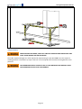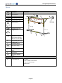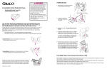
1
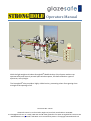
Operators Manual With the light weight and robust Stronghold® Mobile Anchor Point System workers can operate safely and securely around open window spaces, lift shafts and other types of apertures, at any height. The Stronghold® also provides a highly visible barrier, preventing others from getting close enough to the opening to fall. Document No: 3 2013 Glazesafe Limited. 1 Turnford Villas, Highroad, Turnford, Hertfordshire. EN10 6BE E: [email protected] T: +44 (0) 1992 302 133 w: www.glazesafe.com www.stronghold-fall-restraint.com STRONGHOLD is a registered Trade Mark and is Protected by Patent. © Copyright 2013 Glazesafe Ltd Stronghold Operators Manual Contents Safety and Important Information ...................................................................................................... 2 Notes, Cautions and Warnings Used in this Manual ............................................................................ 2 Warranty, Guarantee and Liability ...................................................................................................... 3 Introduction ....................................................................................................................................... 3 Installation Scenarios .......................................................................................................................... 5 Standard Installation ....................................................................................................................... 5 Installation for Two Operatives ....................................................................................................... 5 Installation Over an Object.............................................................................................................. 5 Extended Height Aperture Installation ............................................................................................ 5 Installation with Load Straps ........................................................................................................... 6 Lift Shaft Barrier .............................................................................................................................. 6 Identification Name Plate........................................................................................................................6 In the box / Unpacking ........................................................................................................................ 7 Assembling Stronghold® .................................................................................................................... 9 Selecting an Assembly Area............................................................................................................. 9 Measure the Window Aperture and Select Required Components .................................................. 9 Assembly and Installation Procedure ............................................................................................ 10 Adjustments ................................................................................................................................. 16 Using the Stronghold® ..................................................................................................................... 15 Before Use .................................................................................................................................... 15 Attaching a Worker Lifeline ........................................................................................................... 18 Disassembling and Storing Stronghold® ........................................................................................... 19 Maintenance .................................................................................................................................... 19 Spares............................................................................................................................................... 18 Specification ..................................................................................................................................... 21 Stronghold® Diagrams ..................................................................................................................... 22 Stronghold® Training ....................................................................................................................... 22 Certification ...................................................................................................................................... 23 Contact ............................................................................................................................................. 23 Examination Report Card .................................................................................................................. 24 Equipment Record ............................................................................................................................ 25 Page 1 Stronghold Operators Manual Safety and Important Information SAFETY FIRST: STRONGHOLD® IS A SAFETY DEVICE AND ALL SAFETY NOTICES AND PROCEDURES MUST BE READ AND FOLLOWED CAREFULLY BEFORE USE. The User must read, understand and follow this User Manual before using this equipment. This User Manual must be kept in a safe place for future reference with inspection records and should be used as part of a user training program. It is essential for the safety of the user that if the Glazesafe Stronghold® is resold outside the original country of destination the reseller shall provide full instructions in the language of the country in which this equipment will be used. The Stronghold® shall only be used by a person trained and competent in its safe use, who understands fully the potential hazards related to the Stronghold®. Only people who are physically and mentally fit and healthy, not under the influence of drugs or alcohol are permitted to use this equipment. Seek advice from your Doctor before use if you are uncertain about your ability. Also seek advice from a Doctor if you are pregnant and plan to use this equipment. Minors must NOT use this equipment. Check each individual item before use and remove from operation if there are any signs of damage or wear. Do not use Stronghold® against open windows or apertures that are outside of the specified maximum width dimensions. Do not modify the equipment in any way without prior written consent from Glazesafe Ltd. Do not use Stronghold® to support more than two workers. Use the Stronghold® with the specified methods in this user manual only. If the Stronghold® is extended to its maximum height, a safety barrier strap must be attached to the two side assemblies to prevent people from walking beneath the top bar. The Stronghold® provides an anchor point for fall restraint, fall arrest and industrial rope access. Ensure that the correct sub components are used to suit the working method and ensure there is a rescue plan in place. The Stronghold® requires users to wear full body harnesses only. No other forms of body holding device are acceptable. Keep all harnesses, work positioning equipment and Horizontal Safety Lines safe from damage during storage and transportation. Keep all components in the bags/boxes supplied with the equipment. Do not use Stronghold® in poor weather conditions, such as heavy rain or high winds. Any use of the equipment outwith its intended purpose renders the guarantee and liability null and void. Notes, Cautions and Warnings Used in this Manual The Notes, Cautions and Warnings used within this manual follow an established convention: Notes emphasize important information by visually distinguishing it from the rest of the text. Cautions draw special attention to anything that could damage equipment. WARNINGS INDICATE AN IMMINENTLY HAZARDOUS SITUATION WHICH, IF NOT AVOIDED, COULD RESULT IN DEATH OR SERIOUS INJURY. Page 2 Stronghold Operators Manual Warranty, Guarantee and Liability The content of this manual does not form part of any agreement or undertaking with or by Glazesafe Limited. Glazesafe Limited reserves the right to make changes to this manual without prior notification. Glazesafe Limited does not assume any liability for errors that may exist in this manual or arising from the misinterpretation of its content by the user. The Stronghold® is provided with a 12 month guarantee from Glazesafe Ltd commencing on the date of purchase. This Guarantee will be made void if the care and maintenance procedures specified in this user manual are not followed and the visual inspection records are not retained. Guarantee covers all parts except any harnesses, horizontal life lines, work positioning lines and connectors. These parts are covered by their individual manufacturer’s warranty, information of which is supplied with the parts. Introduction The Glazesafe Stronghold® is a mobile anchor point system that allows workers to be anchored, via a lifeline and a harness, to a secure anchoring point so that they can work safely through open windows and other building apertures, such as a lift shaft, at any height. The Stronghold® additionally provides a safety barrier around open windows and apertures, reducing the ‘fall from height’ risk to other workers or members of the public in the work area. The Stronghold® can be installed against the wall either side of window spaces and apertures with the following maximum dimensions: Width: up to a maximum of 3.7m Height: up to a maximum of 2m from the work area floor level Page 3 Stronghold Operators Manual Page 4 Stronghold Operators Manual Installation Scenarios The Glazesafe Stronghold® FOLD AWAY can be adjusted so that it can be installed in a number of operational scenarios. Standard Installation A standard installation is where Stronghold® is installed against a flat wall, with a standard height aperture (up to 2m above the work area floor level) and no objects or furniture restricting access to the aperture. A standard installation is for up to two operatives with a single horizontal lifeline up to 3.7m wide. Installation for Two Operatives This is similar to the Standard installation however, the addition of a second horizontal lifeline allows a second operative to be attached to the Stronghold® independently allowing both operatives to move freely on a separate life line without meeting in the middle. Installation Over an Object If the window space, or building aperture, to be worked at is above an object, such as a bath or kitchen worktop, Stronghold® can still be installed. The horizontal arms and vertical legs are telescopically adjusted to suit the site. Extended Height Aperture Installation If steps are required to reach a high situated window, a building aperture, or work is required over an obstacle the Stronghold® can be adjusted to 2m in height. The additional safety barrier strap is then fitted. Page 5 Stronghold Operators Manual Installation with Load Straps Optional Load Straps can be connected to separate dedicated anchor hangers on the Stronghold side units. These Load Straps can be connected to a window frame, tools or different industry objects. Stronghold LIFT Stronghold LIFT® can be used as a highly visible barrier and work force anchor point for when work is required to be carried out on a lift not working or installation/ modernisation situation. A safety net accessory is available which encloses all three vertical sides, maximising safety. Identification Name Plate The ID Name Plate found on the Side Unit of the Stronghold provides the following information. The characters shown below in red and also in bold italic on the sample name plate below will be stamped on the actual Stronghold. Item ID Code : - (A) 00 00 00 (B) STRV ‘A000000 A’ (C) ‘1R’ (A) 00 00 00 Date of Manufacturer. DD MM YY (B) ‘A000000 A’ First letter = Manufacturers Code . Six Numbers = Individual Product Serial Number. Last letter = Distributor code. (C) ‘1R’ Version of the Stronghold. Mark ‘1’ ‘R’=‘RIGID’ or ‘F’=’Folding’ Page 6 Stronghold Operators Manual Included / Unpacking The following components are provided Stronghold FOLD AWAY: Item Qty. Description 1 and 2 1A and 2A 1B and 2B 3A and 3B 3A-1, 3A-2 and 3B-1, 3B-2 4A and 4B 4A-1, 4A-2 and 4B-1, 4B-2 5 and 5A Shown assembled 2 2 2 2 4 2 4 16 1 7 1 Shown assembled 2 Not shown Not shown 1 1 Foot Plate Unit Side Unit Wall Pad Arm Unit Short Connector Bar - (1300mm - 2000mm window width) Short Arm Unit - (825mm) Long Connector Unit - (2000mm - 3700mm window width) Long Arm Unit - (1200mm) Adjustment Locating Pin with retention cable and ‘R’ Pin Pair of fitted Petzl Anchor Hangers used to support one person. (Second set optional and required for second person use.) Horizontal Lifeline with bag, suitable to support two people. (Second lifeline optional and required for independent, second person use.) 10mm Maillon Pear Shape Galvanised Steel. (Second pair optional and required for second person use.) Safety Barrier Strap User Manual and demonstration films on CD 2B 2A 3B-2 3B 4B 1B 3B-1 7 2 1A 5, 5A 3A-2 3A 4A 3A-1 Page 7 6 1 Stronghold Operators Manual The following components are OPTIONAL: Item Qty. Description Not shown 1 Not shown 1 Not shown 2 Horizontal Lifeline with bag, suitable to support two people. (Second lifeline optional and required for independent, second person use.) Full body harness with bag. (Second harness optional and required for second person use.) ‘Frame Anchor Set’ including Karabiners and Load Straps . Not shown 1 Safety Net and 4x Karabiners (Stronghold LIFT) Not shown 2 Post plates – Attached to the flat wall plates these allow the Stronghold to be positioned against vertical posts. Please keep the box and store all items back in the box when not in use. Page 8 Stronghold Operators Manual Assembling Stronghold® Selecting an Assembly Area ENSURE YOU SELECT A WORK AREA THAT PROVIDES READY ACCESS TO WHERE STRONGHOLD® WILL BE INSTALLED BUT A SAFE DISTANCE AWAY. IF THE BUILDING APERTURE, LIFT SHAFT OR WINDOW SPACE IS ALREADY OPEN AND EXPOSED, A FALL FROM HEIGHT COULD RESULT IN DEATH OR SERIOUS INJURY. Select a suitable working area for the assembly of the Stronghold®. The Stronghold® is assembled and then moved up to the building aperture. Ensure when assembling that you are far enough away from the window/aperture for safe working practice. Do not forget to leave enough space between the wall and the Stronghold® frame to be able to safely slide wall pad arm units 1B and 2B into position. Measure the Window Aperture and Select Required Components BE CAREFUL WHEN MEASURING THE BUILDING APERTURE OR WINDOWS SPACE IF IT IS ALREADY OPEN AND EXPOSED. A FALL FROM HEIGHT COULD RESULT IN DEATH OR SERIOUS INJURY. Measure the width and height of the aperture, to allow the most suitable Stronghold® components to be selected during assembly. Select the appropriate combination of short or long components to assemble the telescopic arm assemblies (top and bottom) that are most suitable for the width of aperture. Typically: For windows/apertures up to 2000mm (2.0m) wide (inside measurements), use short connectors units (3A and 3B) and short arm units (3A-1, 3A-2, 3B-1, 3B-2). For windows/apertures between 2000mm (2.0m) and 3500mm (3.5m) wide, use long connectors units (4A and 4B) and long arm units (4A-1, 4A-2 and 4B-1, 4B-2). Apertu re Wid th For use of the Stronghold® against a solid wall, position the Wall Plates along the wall as far away from the edge of the window aperture. This will allow a larger work area to work in. For use of the Stronghold® against a plasterboard wall position the wall plates 25mm away from the window aperture. If there is a large wall area either side of the window aperture position the centre of each wall plate approximately every 400mm away from the edge of the window aperture (position of the stud work behind the plasterboard). For higher apertures, where Stronghold® will be installed at full height, ensure you have the safety barrier strap in position. For two workers, ensure you have two safety horizontal lifelines. Page 9 Stronghold Operators Manual Assembly and Installation Procedure Refer to the following Step by Step image guide for setup. BEFORE ASSEMBLY, CHECK THAT ALL EQUIPMENT ITEMS ARE IN GOOD ORDER. PAY PARTICULAR ATTENTION TO CONNECTING ANCHOR PLATES, LIFELINES AND HARNESSES. IF ANY PARTS ARE FOUND TO BE DAMAGED OR WORN REMOVE THE COMPLETE SET FROM OPERATION IMMEDIATELY AND INFORM THE DUTY HOLDER. DO NOT USE THE EQUIPMENT AGAIN UNTIL THE EQUIPMENT IS CONFIRMED TO BE IN GOOD ORDER IN WRITTING BY A COMPETENT PERSON. A FALL FROM HEIGHT DUE TO DAMAGED ITEMS COULD RESULT IN DEATH OR SERIOUS INJURY. 1 Position the foot plate units: 2 Assemble the top and bottom telescopic arm assemblies using the appropriate length connectors and arm units: Site both foot plate units 1 and 2 into the assumed working position at a greater distance apart than the window/aperture, with the feet facing towards the aperture wall. Slide short telescopic arm 3A-1 into short connector 3A (or long telescopic arm 4A-1 into long connector 4A) and leave two holes showing. Slide short telescopic arm 3A-2 into the other end of short connector 3A (or long telescopic arm 4A-2 into long connector 4A) and leave two holes showing. Page 10 Stronghold Operators Manual 3B-2 3B 3B-1 3A-2 3A 3A-1 3 Extend the bottom telescopic arm assembly in to the footplate units and secure: Slide the short arm unit 3A-1 (or the long arm 4A-1) into the clamp arrangement of foot plate unit 1, ensuring that the holes are running parallel to the floor and that there is a hole visible either side of the foot plate clamp. Lightly tighten the clamp screw 6 and insert a locating pin 5 into both holes either side of foot plate clamp arrangement on unit 1. Fit the retention cables and R pins 5A. Extend the second short arm unit 3A-2 (or the long arm 4A-2) in to the clamp arrangement of foot plate unit 2 until the holes line up in the two units. Insert an adjustment locating pin 5 and fit the retention cable and R pin 5A. If necessary, reposition foot plate unit 2 so that the holes in the second short unit 3A-2 (or long arm 4A-2) are shown either side of the screw clamp 6. Page 11 Stronghold Operators Manual 4 5 Insert locating pin 5 into the hole and secure with an R-clip 5A. Lightly tighten the clamp screws 6. Fit the side units to the foot plate units: Slide side unit 1A onto foot plate unit 1 and leave one hole showing. Position, by sliding 1A up and down, until the holes in 1A and 1 are aligned. Once the holes are aligned, insert adjustment locating pin 5 into the hole and secure with R-clip 5A. Repeat this for units 2A and 2, securing with 5 and 5A. Extend the top telescopic arm assembly in to the side units and secure: For this assembly, all holes should be running vertically. Insert adjustment locating pin 5 into the second hole in of short arm 3B-1 (or the long arm 4B-1) and secure with R-clip 5A. Slide the telescopic arm into the top screw clamp arrangement on side unit 1A until the adjustment locating pin 5 stops against the clamp arrangement. Page 12 Stronghold Operators Manual Extend the top short connector 3B (or the top long connector 4B) until the holes line up. Insert adjustment locating pin 5 and secure with R-clip 5A. Extend the short arm 3B-2 (or long arm 4B-2) into the top clamp arrangement on side unit 2A. Insert adjustment locating pin 5 through 3B and 3B-2 (or 4B and 4B-2) and secure with R-clip 5A. Tighten clamp screw 6. Fit the remaining adjustment locating pins 5 and secure with R-clips 5A. See illustration on next page. 6 Fit wall pad arm units: Extend the wall pad arm unit 1B until the chosen length is achieved. Allow yourself as much work space as possible. Align the holes in 1B and 1A and insert adjustment locating pin 5 into the hole and secure with R-clip 5A. Repeat the above using units 2B and 2A, securing with 5 and 5A. Cover the wall pad arm units 1B and 2B with shoe covers 9 (not shown). Page 13 Stronghold Operators Manual 7 Attach safety strap and harness lines: Please read through the Petzl Horizontal Line User Manual. Attach the Petzl Horizontal Life Line 7 to the Petzl anchor plates 8 using the Pear Shaped Maillon 10. Extend the length of the rope using the rope grab and connect the rope grab to the Petzl anchor plates 8 on the opposite side. Ensure that the Pear Shaped Maillon 10 are screwed totally shut. Pull the rope until the rope has minimal slack and tie an over hand knot in the rope preventing the rope from running through the rope grab. Optional second person use: Attach the second Petzl Horizontal Life Line 7 in the same way if a second worker is required to harness to the Stronghold®. When the Stronghold® is extended to its maximum height it may be possible for personnel to walk under the top frame unaware of the circumstances. To prevent this happening a safety barrier strap is provided and should be attached to side units 1A and 2A as shown. Page 14 Stronghold Operators Manual 7 Position the assembled Stronghold® against the wall: Be careful when moving Stronghold® over finished flooring as grit embedded in the feet could scratch or mark the floor. Move by pushing and lifting the assembly up to the wall, check that the frame width is greater than the aperture in the wall and position equally spaced each side of the aperture. The space between the wall pad on 1B and 2B and the edge of the window/aperture on a solid wall must be as much as possible. For plaster board walls fit the wall plates over the stud beams where possible otherwise position the wall plates 25mm in from the edge of the window opening. To obtain your required working distances move and secure all of the adjustable sections in equal distances as much as possible. You may require Units 1B and 2B can be extended to different lengths to meet obstacles around the opening such as architrave. There are additional holes at the end of units 1A and 2A to allow units 1B and 2B to be positioned slightly differently. This will allow for any differences in the depth of wall on either side. The Stronghold® framework must be assembled and positioned as square as is practical against the wall. Page 15 Stronghold Operators Manual Adjustments FROM OUTSIDE THE FRAME, CHECK ALL PINS AND SCREWCLAMPS ARE SECURE AND TIGHT AFTER MAKING ANY ADJUSTMENTS. The width, depth and height can all be adjusted by repositioning the pins 5 and 5A to suit the required working positions. The width may require the four screw clamps 6 to be loosened and retightened in four positions. THE FRAMEWORK MUST NEVER BE USED IF THE DIMENSIONS ARE GREATER THAN THE MAXIMUM GIVEN IN THIS USER MANUAL. Page 16 Stronghold Operators Manual Using the Stronghold® Before any work using the Stronghold® always cordon off an area below the work area preventing injury from potential falling objects keeping in mind that falling objects move horizontally as well as vertically in a fall. Use all relevant safety signs and barriers. Once attached, with the Maillon Karabiner screwgates shut completely, the worker can step under the Stronghold® frame and adjust their work positioning equipment. The work positioning line must be set so that the user begins closest to the Stronghold® and then adjusts the line to allow movement closer to the opening until the correct distance is achieved. The user can be anchored by the front or rear connectors on their harness depending on the requirements of the job. The user must only change this anchor position when they are safely on the outside of the Stronghold ® work area, where they are unable to fall. Please refer to the user manual for your chosen harness and work positioning equipment. The worker should take into account play in the Horizontal Life Line and adjust the work positioning equipment accordingly so that they can reach all of the work area comfortably but with only minimal tolerance. Keep all tools and debris off of the floor/work surface in the work area. Tools and debris should be placed outside of the work area until required. Optional Load Strap Set: The 1T Load Strap Set 11 is used to anchor a window frame (or other equipment depending on industry use) to the Stronghold® whilst it is being lifted into the opening. The user must take all reasonable measures to ensure that the position that the load straps are connected to the frame or equipment is suitable to anchor the load straps to. Glazesafe Ltd can not accept liability for any injury or damage caused by failure of a point on a window frame or other object that is chosen by the user to anchor to. Attach the Load Strap Set 11 and the Karabiner to the Optional third set of Petzl anchor plates 8 and ensure the screw gate is shut completely. With the Karabiner in the loop of the free end of the Load Strap wrap the Load Strap 11 around the window frame (be sure to allow enough play to allow free movement of the window frame into the aperture) preferably the mullion or transom bar and clip the Karabiner to the Load Strap, anchoring the window frame to the Stronghold®. Wrap the load strap around the frame until the required length is achieved. Repeat these steps for the second Load Strap on the second side. Before Use BEFORE USING STRONGHOLD® THE EQUIPMENT MUST BE CHECKED FOR CORRECT INSTALLATION AND TO ENSURE THERE IS NO WEAR OR MISSING PARTS. INCORRECT INSTALLATION OR WORN COMPONENTS MAY CAUSE THE STRONGHOLD® TO FAIL. A FALL FROM HEIGHT COULD RESULT IN DEATH OR SERIOUS INJURY. 1 FROM OUTSIDE THE STRONGHOLD® FRAME, CHECK THAT THERE ARE NO INDICATIONS OF WEAR OR DAMAGE TO ANY COMPONENTS. PAY PARTICULAR ATTENTION TO CONNECTING ANCHOR PLATES AND THEIR FIING NUTS AND BOLTS, LIFELINES AND HARNESSES. Page 17 Stronghold Operators Manual 2 CHECK THAT THE WIDTH OF THE FRAMEWORK IS GREATER THAN THAT OF THE WINDOW/APERTURE AND THAT THE COMPLETE WALL PLATE SURFACE IS AGAINST THE WALL. 3 CHECK THAT THE ENDS OF 3A1, 3A2, 3B1 AND 3B2 ARE OUTSIDE OF THE OUTER EDGES OF 1, 1A AND 2, 2A WITH ONE HOLE SHOWING AND SECURED WITH ITEMS 5 AND 5A POSITIONED IN THESE HOLES. 4 CHECK THAT ALL ITEMS 5 AND 5A ARE FIXED AND SECURED IN POSITION INTO THE FOUR HOLES. 5 CHECK THAT ALL ITEMS 6 ARE TIGHTENED IN ALL FOUR POSITIONS. 6 IF STRONGHOLD® IS AT FULL HEIGHT, ENSURE THE SAFETY BARRIER STRAP IS INSTALLED. Attaching a Worker Lifeline MAXIMUM OF TWO WORKERS PER HORIZONTAL LIFE LINE AND PER STRONGHOLD®. EXCEEDING THIS MAXIMUM COULD CAUSE THE STRONGHOLD® TO FAIL. Before stepping in to the Stronghold® work area, each worker (maximum two), attaches their harness line connector to the Horizontal Lifeline on the Stronghold®, using a screw gate Karabiners (supplied). The Karabiners should be able to slide freely along the Horizontal Lifeline. Once the user/s are attached and has adjusted their personal work positioning lines so that they are restricted close to the Stronghold® the worker can step under the Stronghold® frame, adjust the work positioning line accordingly, test the restraint system by pulling against it and then start to work. Page 18 Stronghold Operators Manual Disassembling and Storing Stronghold ® Be careful when moving Stronghold® away from the Window/Aperture over finished flooring as grit embedded in the feet could scratch or mark the floor. Disassemble Stronghold® in the reverse order of the assembly instruction and replace back into the supplied packaging. Scheduled Inspections A full visual inspection should be carried out on initial receipt, before use and annually by a competent person that has received certificated training to do so. A pass/fail record should be completed (template supplied) after each visual inspection and this document should be retained for the life of the product whilst in use. Maintenance Taking care of the Stronghold® fall protection equipment will ensure a long and dependable usage of the items. After use the equipment should always be cleaned of any dirt, corrosives or contaminants. Particular attention should be given to the lifeline and body harness as an uncleaned build up of silicon, filler, paint etc. can be detrimental to the condition of these items over a period of time. Lifeline and Safety Harness – Wipe off all surface dirt with a damp sponge using plain water. Then use a mild solution of water and commercial soap or detergent to obtain a thick lather by vigorously going back and forth. Then remove the soapy lather using the sponge and clean water. When all the lather is removed allow to dry. When cleaning inspect the Lifeline and Safety Harness for any defects or wear. If damage is found refer to the manufacturers’ instructions and take the necessary actions. If unsure replace the damaged items. Stronghold® Framework – After use, dismantle and clean the framework using a damp cloth and a mild detergent. Allow to dry. Remove any grit from the wall plate neoprene pads and from the rubber matting on the feet. Clean with a damp cloth and allow to dry. When cleaning inspect the framework for any damage. Pay particular attention to the Lifeline mounting points. Any damage to these means that the equipment cannot be used until they have been replaced. When dry replace all the items into their respective containers. Use a silicone spray on all white uPVC to allow telescopic sections to move smoothly. Regular inspection should be carried out before each use and at least every six months. If used daily then a more frequent inspection should be carried out. All inspections should be by a competent person. (Test training available on request) Page 19 Stronghold Operators Manual Spares Item No Description 1, 2 Foot Plate Unit 1A, 2A Side Support Unit 1B, 2B Wall Pad Arm Unit 3A, 3B Short Connector Unit 3A-1, 3A-2 3B-1, 3B2 4A, 4B 4A-1, 4A-2 4B-1, 4B2 Illustration Short Arm Unit Long Connector Unit Long Arm Unit 5, 5A Adjustment Locating Pins (5) with retention cables and ‘R’ Pins (5A) 6 Clamp Screw (part of 1, 1A and 2, 2A 7 Horizontal Lifeline Not shown Safe Barrier Strap 8 Set of Petzl Anchor Plates 9 Shoe Covers 10 10mm Pear Shaped Maillon Optional Extras 11 1T Load Strap Set Including: 1 pair of Petzl Anchor Plates 1 Pair of 1T load Straps 4 Karabiners Page 20 Stronghold Operators Manual Specification Maximum Aperture Height 2m (from floor) Maximum Aperture Width 3.7m Maximum Number of Workers 2 Maximum Depth back from walls 1.9m Maximum Window Width with Standard Bars Maximum Window Width with Extended Bars Page 21 Stronghold Operators Manual Stronghold® Diagram Adjusted to minimum height and depth Page 22 Stronghold Operators Manual Stronghold® Diagram Adjusted to maximum height and depth Page 23 Stronghold Operators Manual Stronghold® Training Please read and understand this User Manual before use. The Stronghold® should only be used by people deemed to be competent by the duty holder. Training is recommended on this product and maybe a legal requirement where you operate. Glazesafe works in a Strategic partnership with our manufacturers and a chosen training provider to offer a specialised Stronghold® course for users, managers and internal training staff. The course includes: 1: Product Introduction and Overview 2: Product Demonstration 3: PPE Requirements 4: Candidate Practical Participation 5: Assessment Paper 6: Instructor Feedback Every employee receives 1 2 1 Training, an Electronic Portfolio, Attendance Certificate, Certificate of Competence and a Competence Card [assuming delegates meet the minimum criteria] Courses are also available for other areas of the business and we can provide training to 1. Training for your trainers. 2. Training for Surveyors, Operations Managers and Health and Safety Managers. Page 24 Stronghold Operators Manual Certification and Conformity Stronghold® Conforms to: UK and Europe. BS EN795 B :2012, TS 16415 :2013, Australia and New Zealand. AS/NZS 5532: 2013, USA ANSI. Z359.1 :2007, Meets OSHA requirements. Horizontal Life Line. EN358. EN795 C. EN1795 B Hanger Plates Coeur 10mm. EN795. EN959 Petzl Maillon 10mm Pear Shape Galvanised Steel Connectors (or an alternative connector). EN362. EN12275 Contact For all enquiries including sales, technical, training, warranty and spares contact: Glazesafe Limited 1 Turnford Villas Highroad Turnford Hertfordshire EN10 6BE E: [email protected] T: +44 (0) 1992 302 133 W: www.glazesafe.com W: www.stronghold-fall-restaint.com ‘Stronghold’ is a Registered Trade Mark and is protected by a Patent Pending. Page 25 Stronghold Operators Manual Examination Report Card Item ID Code 00 00 00 A000000 A Date Inspector Name dd/mm/yyyy Surname Date of Initial Receipt dd/mm/yyyy Company Name & Branch Comments/Actions Page 26 Pass/Fail Signature Stronghold Operators Manual Equipment Record Stronghold Item ID Code Inspected by and on behalf and Glazesafe Ltd Date of purchase Date of first use User name Manufactured and supplied by: Youngman Group 28 The Causeway, Heybridge, Maldon, Essex. CM9 4LJ, United Kingdom T: +44 1621 745900 W: www.youngmangroup.com For: Glazesafe Ltd. 1 Turnford Villas, Highroad, Turnford, Broxbourne, Hertfordshire. EN10 6BE, United Kingdom T: + 44 (0) 1992 302 133 W: www.glazesafe.com W: www.stronghold-fall-restraint.com Attestation of conformity: Production control phase Page 27