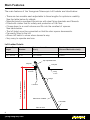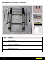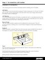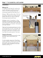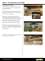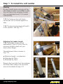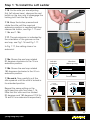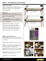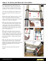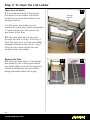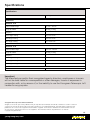
1
Use and Care Instructions:
Youngman Telescopic Loft Ladder
Models:
2.6m and 2.9m
Safety
Please ensure you read the Safety section in this manual starting on page 4 before
installing or using the equipment. Your safety and that of others is important.
Introduction
The Youngman Telescopic Loft
Ladder is manufactured in
aluminium with an anodised finish.
It is built to withstand the toughest
handling and working conditions.
Suitable for home and commercial
use. Spare parts are readily
available.
We recommend you take time
and read these instructions. They
contain full installation details and
describe how to deploy the ladder
and how to store it after use to
ensure you get the very best
performance from your purchase.
Keep these instructions in a safe
place for future reference.
Youngman Group Ltd
The Causeway, Maldon, Essex, CM9 4LJ, UK
t: +44 (0)1621 745900
e: [email protected]
youngmangroup.com
For more information about the
Youngman Telescopic Loft Ladder
and other products, please visit our
website www.youngmangroup.com
Contents
Introduction1
Safety1
In the Box2
Important Safety Information3
Safety Considerations3
Servicing and Spare Parts3
Main Features4
Loft Ladder Components Identified5
Step 1: To Install the Loft Ladder
6
Step 2: To Close and Stow the Loft Ladder
13
Step 3: To Open the Loft Ladder
14
Specifications15
Warranty16
In the Box
Carefully remove your Youngman Telescopic Loft Ladder and fitments and accessories
from the box it arrived in. It is recommended that you retain this packaging should the
item need to be returned under warranty. The following items are supplied:
• Ladder (x1)
• Mounting brackets (x2)
• Swivel arms (2)
• Hinge swivel pins (x2)
• Ladder sub-frame carrier bar (x1)
• Ladder sub-frame carrier tubes (x2) - supplied attached to mounting brackets
• Springs (x2)
• The User Manual (this publication)
• Telescopic pole with hook
• Mounting bracket fixing screws (x8)
These items are shown in the illustration opposite.
2
youngmangroup.com
Important Safety Information
Warning
For your safety, please read all the safety instructions in this Manual
before using the Youngman Telescopic Loft Ladder.
Safety and quality is of paramount importance when manufacturing Youngman
products.
Important
Read these instructions before installing the Youngman Telescopic Loft Ladder.
Important
Install the Youngman Telescopic Loft Ladder according the instructions given in this
Manual and on the labels affixed to the equipment.
Safety Considerations
General
• Do not install or use the Youngman Telescopic Loft Ladder if damaged in any way.
• Never exceed the maximum load of 150 kg.
• Never operate any of the red buttons while on the ladder or allow anyone else to
operate the buttons while it is in use.
Cleaning
• Do not use any abrasive or chemical solvents.
• Periodically clean with a soft damp cloth. We recommend occasionally spraying
with a silicon spray.
How to Dispose of this Product
When the unit has reached the end of its life, contact your local council regarding
available recycling or disposal options.
Servicing and Spare Parts
When the unit has reached the end of its life, contact your local council regarding
available recycling or disposal options.
3
youngmangroup.com
Main Features
The main features of the Youngman Telescopic Loft Ladder are listed below:
• There are two models each adjustable to three lengths for optimium usability.
See the table below for details.
• Manufactured in anodised Aluminium with steel fixing brackets and fitments.
• Fitted with rubber feet for safety and protection of the floor.
• Closes down to a small volume and fits into the smallest of spaces.
See table below.
• The loft hatch must be converted so that the door opens downwards.
• Permantly fitted in the loft.
• Allows loft hatch to close when stowed a way.
• Very easy to operate and use.
Loft Ladder Details
Floor to Floor
Height
Model
Number
Minimum Hatch Size
(W x L)
Overhang
(Distance Behind the Joist)
217 - 261cm
TL24
510 x 600cm
235mm
243 - 288 cm
TL30
510 x 600cm
235mm
Top adjustable tube
Loft joist
Loft joist
Ceiling
In room
Ceiling
In room
Floor to ceiling measurement
Floor to floor measurement
Rungs
Loft door
Stile tubes of ladder
Loft ladder
Floor in room
4
youngmangroup.com
Loft Ladder Components Identified
2
2
4
3
4
1
9
7
7
10
6
6
5
8
Parts
Components
1
Ladder
2
Mounting brackets (x2)
3
Swivel arms (x2)
4
Hinge swivel pins (x2)
5
Ladder sub-frame carrier bar (x1)
6
Ladder sub-frame carrier tubes (x2)
7
Springs (x2)
8
Telescopic pole with hook (x1)
9
Bracket fixing screws (x8)
10
Instructions
5
youngmangroup.com
Step 1: To Install the Loft Ladder
Installation Consideration
The following points should be considered before installing the Loft Ladder.
Loft Hatch
The loft hatch must be downward opening. It may be necessary to refit your loft hatch
door so that it opens downwards so that the hatch when open hangs down behind
the ladder when it is deployed.
Loft Opening
It is recommended that the loft ladder is installed so that it is orientated parallel to the
longer side of the opening. This will give the user more comfortable access to the loft
and will be easier for the user to take items into the loft.
Secure Fixing
The two fixing brackets supplied must be attached to a secure part of the loft
structure such as a ceiling joist or sound timber bridging and securely fastened to
the joists.
Footprint
When the ladder is opened there should be enough space available at the base of
the ladder for a person to easily and safely get onto and climb the ladder.
Right
mounting
bracket
Left
mounting
bracket
Ceiling
joist
CL
Loft door
opening down
Loft aperture
600 x 510 mm
minimum
Tools
You will need the following tools and materials: Pencil, set-square and measuring
tape (mm) for marking out.
A drill and a 4mm drill bit for drilling the bracket fixing holes and a Posidrive
screwdriver for tightening the eight bracket fixing screws.
Strong string to extend the springs during installation.
6
youngmangroup.com
Step 1: To Install the Loft Ladder
Installation
Take the first bracket and place it on the
mounting board so that it is placed over
the bracket centre line and slide it until
the lower screw hole is centred on this
line. Mark the centre point of this hole.
Fixing the Brackets
1.3 Remove the bracket and drill a 4mm
diameter hole at the position just
marked.
Fix the bracket using one of the fixing
screws supplied. Similarly drill the other
three holes (one on top) and screw in
the other screws. Repeat for the other
bracket, see Fig 1.3.
............
1.2 Refer to Fig 1.2 and Fig 1.3. The
brackets are supplied with their ladder
sub-frame carrier tubes fitted. Note that
these brackets are ‘handed’, left bracket
and right bracket.
............
Measure 188 mm either side of this line
and draw a vertical line at these points
greater than 90 mm long to mark the
mounting bracket centre lines.
Centre Line
1.1
188mm
188mm
............
Marking Out
1.1 Measure and draw the ‘centre line’
on the ceiling joist midway across the
width of the loft opening where the
mounting brackets will be fitted, Fig 1.1.
Ceiling Joist
1.2
Mounting Bracket
Fixing Positions
Ceiling Joist
Left Mounting
Bracket
Left Mounting
Bracket
Left Mounting
Bracket
1.3
Ceiling Joist
Sub-Frame
Carrier Tubes
7
youngmangroup.com
Step 1: To Install the Loft Ladder
Swivel Arm
1.4. Place the Right Swivel arm in
position on the Right Mounting bracket
and align their holes, Fig 1.4.
1.4
1.5
1.5. From the outer edge, guide the
Hinged swivel pin through the arm and
bracket holes and push in completely,
Fig 1.5.
Repeat this procedure with the Left
Swivel arm and the Left mounting
bracket using the other Hinged
swivel pin.
1.6
1.6. The installation will now be at the
stage shown in Fig 1.6.
Attaching the Springs
1.7. Slide the Ladder sub-frame carrier
bar into the hole in one of the
sub-frame carrier tubes, see Fig 1.7.
Now slide the two spring eyelets onto
the bar.
1.8. Slide the other end of the carrier
bar into the corresponding hole on the
other sub-carrier tube, Fig 1.8.
There is groove near each end of the
bar for the purpose of holding the
spring in place when installed, see
Fig 1.8 (inset). Locate each spring in
these grooves.
8
youngmangroup.com
Sub-Frame Carrier Tube
1.7
Sub-Frame Carrier Bar
1.8
Step 1: To Install the Loft Ladder
Extending the Springs
The next step is to anchor the free end
of the spring to its anchor point on the
hinged swivel pin.
1.9
Lay the swivel arms back so they are
horizontal. Hook a loop of strong string
to the end of the spring.
1.9. Lift the sub-frame carrier tube
above the horizontal and pull the string
to extend the spring so that it reaches
and clips on to the hinged swivel pin,
see Fig 1.9 and inset for close-up of
spring on the pin. Remove the string.
1.10
1.10. Now slide the spring eyelet along
the pin so that it locates in the groove
on the pin, see Fig 1.10. Repeat for the
other spring.
1.11. The installation will now be at the
stage shown in Figure 1.11.
1.11
9
youngmangroup.com
Step 1: To Install the Loft Ladder
Warning
Be very careful when carrying out the
next stage as there is no ladder to stop
the sub-frame from swinging forward
with considerable force if it is moved
inadvertently.
1.12
1.12. Pull down on the sub-frame
carrier bar until it touches against its
stop.
1.13
1.13. The tensioned springs will hold it
in this position, see Fig 1.13.
Adjusting the Ladder Length
1.14. The ladder length can be
extended by 15cm or 30cm from its
minimum length to best suit your
floor-to-floor height.
1.14
The adjustment tube is shown in
Fig 1.14:
a. Minimum length - no extension
b. Extended by 15cm
c. Extended by 30cm
a
Endcap
Remove the two bolts from the endcaps
and have them ready to fix the swivel
arms to the ladder at step 1.21.
b
10
youngmangroup.com
c
Step 1: To Install the Loft Ladder
1.15. On the side you are adjusting
first (left shown here), depress the red
button on the top rung to disengage the
locking bolt from the top stile.
1.15
1.16. Keep the button pressed and
rotate the stile until the required
extension position is reached and then
release the button, see Figs 1.17 and
1.18a and 1.18b.
Hold in the Button
1.16
1.17. The set extension is indicated by
the orientation of the grooves on the
end cap, see Fig 1.16 and Fig 1.17.
Left stile
clockwise
In Fig 1.17, the setting shows ‘no
extension’.
View from
above top rung
30
15
Top rung
0
Front of ladder
Left stile
clockwise
Left stile
View from
Viewabove
from top rung
30
15
Top Top
rung
rung
0
1.18c and d. Now carefully pull the
stile upwards until the stile is locked in
its extended position.
15
0
Right s
anti-cloc
above top rungLeft stile
90∞ clockwise
clockwise
30
1.18b. Shows the end cap rotated
180 degrees clockwise to the 30 cm
extension position.
1.17
0
3
15
30
1.18a. Shows the end cap rotated
90 degrees clockwise to the 15 cm
extension position.
15
Front of ladder
Front of ladder
Left stile
90∞ clockwise
Left stile
180∞ clockwise
1.18
Righ
anti-cl
3
0
15
15
30
Left stile
90∞ clockwise
15
a
30
b
0
30
0
Repeat the same setting on the
right-hand top stile from step 1.15.
Note that this stile must be rotated
90 degrees and 180 degrees CCW for
15 and 30 cm extensions respectively.
15
Right s
anti-cloc
Left stile
180∞ clockwise
3
0
15
30
youngmangroup.com
Left stile
180∞ clockwise
c
d
11
15
Step 1: To Install the Loft Ladder
Extend the Ladder
1.19. Fully extend the ladder until all
rungs are locked. This is indicated in the
illustration below by the red buttons
being extended.
Important
Ensure that all the red buttons on the
underside of the rungs are in the locked
position, see above right.
1.19
Rung Locked
1.19
It is dangerous to climb or attempt to
climb the ladder when the rungs are not
locked, see right.
1.20. Stand the ladder on the floor
below the loft and rest the ladder
against the sub-frame with the top of
the ladder close to the swivel arms.
Climb the ladder and enter the loft to
gain access the top of the ladder.
Rung Not Locked
1.20
Screw to the Swivel Arms
1.21a. Align the holes in the swivel arm
with the threaded hole in the top end of
the ladder.
1.21b. Finger tighten the bolt supplied.
1.21c. Use an Allen key to tighten this
bolt to securely fix the swivel arm to the
ladder ensuring the location pin
engages with the groove in the endcap.
Repeat for the other side of the ladder.
Location
Pin
1.21
a
b
c
d
1.21d. Shows both sides of the ladder
fastened to the swivel arms.
Installation is now complete.
12
youngmangroup.com
Step 2: To Close and Stow the Loft Ladder
2.1. Depress the two red buttons on
the underside of rung 2 to unlock the
rung, see Fig 2.1 then push the rung
upwards in the direction of the arrows.
2.1
Rung 3
You can now release your fingers from
the buttons and continue to raise the
rung.
When the rung 2 touches rung 3, it will
push in the red buttons and unlock
rung 3. Continue to raise rung 2 to now
move both rungs up together.
Rung 2
Depress
Buttons
and Lift
2.2. Grip the lower stiles and push up
to unlock and close more rungs in the
same way. If you can now place the
stowage bracket (see Fig 2.4) onto the
sub-frame carrier bar, then do so and
ignore paragraph 2.3.
2.3. Insert the plain end of pole into
the holes in rung 1 and rung 2 and lift
up the ladder to close all the rungs and
sit the stowage bracket located on the
rear of the rung 1, onto the sub-frame
carrier bar.
2.4. Use the hook end of the pole and
hook onto the carrier bar to raise the
ladder. During this operation the springs
will pull the ladder into a horizontal
position.
2.3
2.2
Rung 1
Pole
Stowage
Bracket
2.4
Remove the pole and close the loft
hatch.
Pole Hooked
onto Carrier
Bar
13
youngmangroup.com
Step 3: To Open the Loft Ladder
Open the Loft Hatch
3.1. Use the hook end of the pole to
pull down on the Ladder sub-frame
carrier bar to swivel the ladder to the
vertical position.
3.1
Stowage
Bracket
If at this point, the ladder can be
reached by hand then ignore paragraph
3.2 and unhook from the carrier bar
and lower to the floor.
3.2. Pass the plain end of the pole
through the hole in rung 1 and rung 2.
Push the pole up to un-hook the ladder
stowage bracket on the rear of rung 1
from the sub-frame carrier bar and
carefully lower the ladder.
Remove the Pole
3.3. Grip the lower stiles of the ladder
and carefully pull it down and extend
the ladder. Make sure all the rungs are
locked (indicated by the red buttons
being extended below the rungs).
14
youngmangroup.com
Pole Hooked
onto Carrier
Bar
3.2
3.3
Specifications
Specifications
Maximum Load
150 kg
Dimensions
Model No TL24
Floor-to Floor-height
217cm - 261cm
Angle of ladder
65 deg 75 deg
Footprint
/
Max height setting
123 cm 74 cm
Mid height setting
116 cm 70 cm
Min height setting
111 cm 67 cm
Model No TL30
Floor-to-Floor height
243 cm - 288 cm
Angle of ladder
65 deg 75 deg
Footprint
/
Max height setting
135 cm 81 cm
Mid height setting
129 cm 78 cm
Min height setting
123cm 74cm
Construction
Aluminium
Important
The Manufacturer and/or their recognized agents, directors, employees or insurers
will not be held liable for consequential or other damages, losses or expenses in
connection with, or by reason of, or the inability to use the Youngman Telescopic Loft
Ladder for any purpose.
Youngman Telescopic Loft Ladder User Manual
All rights reserved. No part of this publication may be reproduced, transmitted, transcribed, translated or stored in a retrieval
system in any form by any means without the written permission of Youngman® Limited. Technical details contained in this
publication are correct for the equipment model numbers supplied. The Instruction and Reference Manual will be revised
as necessary for subsequent revisions to the equipment. This information will also be published on our website.
Copyright Youngman® 2012.
15
youngmangroup.com
Warranty
Your Youngman Telescopic Loft Ladder is covered by a 12 month warranty.
The Company undertakes to replace or repair, free of charge, any defect which the
Company considers to be due to faulty workmanship or material within 12 months
of the sale date, except for:
• Defects arising from neglect, misuse or unauthorised modifications.
• Damage caused by abuse, misuse, dropping or other similar damage caused
by or as a result of failure to follow transportation, storage, loading or operation,
instructions.
• Alterations, additions or repairs carried out by persons other than the
Manufacturer or their recognized distributors.
• Transportation or shipment costs to and from the Manufacturer or their
recognized agents, for repair or assessment against a warranty claim, on any or
component.
• Materials and/or labour costs to renew, repair or replace components due to fair
wear and tear.
• Faults arising from the use of non-standard or additional parts, or any
consequential damage or wear caused by the fitting or use of such parts.
Youngman Group Ltd
The Causeway, Maldon, Essex
CM9 4LJ, United Kingdom
t: +44 (0)1621 745900
e: [email protected]
youngmangroup.com