1
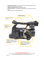
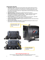
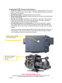
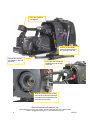
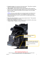
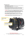
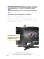
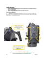
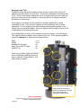
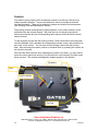
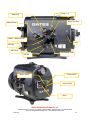
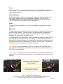
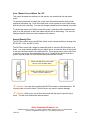
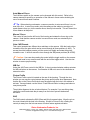
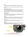
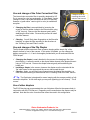
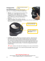
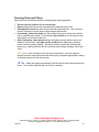
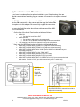
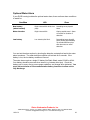
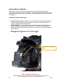
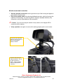
EX1R Underwater Housing Setup, Use, and Care Guide Gates Underwater Products, Inc 13685 Stowe Drive • Poway, CA • 92064 • 858.391.0052 • 800.875.1052 • Fax 858.391.0053 [email protected] • www.GatesHousings.com 12/21/12 1 Gates Housing Setup and Use Congratulations on owning a new Gates housing! You’ve selected a product that will provide years of value and reliable service. This housing was custom designed for the Sony PMW-EX1R camera as a rugged and transportable package. Please read through this entire guide to familiarize yourself with the Gates EX1R housing. The following setup guidelines will explain how to prepare and use your camera and housing so you’ll get the best results from your imaging endeavors. First Time Use Every Gates housing is pressure tested before leaving the factory to ensure a watertight seal. As a precaution, however, it’s a good idea to first use the housing without your Sony EX1R inside. Rough or abusive handling during shipment could have caused unnoticed damage after leaving the factory. In addition, you can get a good feel for the use of an underwater housing without worrying about getting a good shot. You can simply concentrate on the technique of holding the housing in position while fine tuning your personal buoyancy. After removing the housing from its shipping container, carefully inspect for any damage that may have occurred during shipment. If you discover any then contact Gates or your dealer immediately for assistance. Camera / Housing setup Preparing the EX1R Camera Your Sony EX1R will need some preparation before installing into the housing. Remove the lens hood, cap and any external lenses/filters you may have added to the front of the camera. Remove the boom microphone and holder from the camera. The holder will require a small precision phillips screwdriver. Remove the eyepiece from the rear viewfinder. The release button is underneath the eyepiece. Tighten the hand strap to its shortest position and tuck the ‘tail’ back into the hand strap. CAUTION: Failure to perform this step may result in the hand strap becoming caught in the housing seal and allow water intrusion. Rotate the hand grip one ‘stop’ in the clockwise direction from horizontal as shown in the photo below. There is a release button for the handgrip next to the rec/stdby button. Display information. The EX1R camera must be set to display information through the external monitor. This is done by entering the menu of the camera and selecting as follows: MENUVIDEO SETYPbPr/SDI OUT DISPLAYON Gates Underwater Products, Inc 13685 Stowe Drive • Poway, CA • 92064 • 858.391.0052 • 800.875.1052 • 858.391.0053 [email protected] • www.GatesHousings.com 2 12/21/12 Microphone information. If you have the optional microphone installed, set the camera as described in detail on page 21. Slide the manual focus ring to the forward position. Set Zoom to ‘Servo’. This switch is located at the base of the camera under the lens. Install a memory card and charged battery. Remove the boom microphone and holder. Set the zoom switch to ‘Servo’. Remove the eyepiece from the viewfinder. Rotate the hand grip 1 stop clockwise. Tighten the handstrap fully and tuck the ‘tail’ into the leather guide. Remove any caps, lenses or filters from the camera lens. Slide the focus ring into the forward position. Gates Underwater Products, Inc 13685 Stowe Drive • Poway, CA • 92064 • 858.391.0052 • 800.875.1052 • Fax 858.391.0053 [email protected] • www.GatesHousings.com 12/21/12 3 Preparing the Housing Release the latches. Release the three stainless steel safety latches that secure the housing halves. Release the side latches first, followed by the top latch. They have a positive locking feature, so to open them you must first depress the center bar release while lifting the rear lever. Depress the bar and lift the rear lever on both latches at the same time. Open the housing. Separate the rear half of housing from the front. Remove the camera tray from the housing. The tray is released by rotating the locking latches 90 degrees in opposite directions. Refer to the photo. Once released the tray will easily slide out of the housing. Pull out controls on the left side of the front shell as far as they will go. Note that controls will be addressed in greater detail in a subsequent section. Rotate the Rec/Stdby control 90 degrees clockwise so the arm is horizontal toward the rear of the housing. Pull out video and audio connectors (if applicable) and wrap to the side or top of the housing out of the way for camera insertion. Release the latches. Start with the side latches, then the top. To remove the camera tray rotate the latches 90 degrees. Gates Underwater Products, Inc 13685 Stowe Drive • Poway, CA • 92064 • 858.391.0052 • 800.875.1052 • 858.391.0053 [email protected] • www.GatesHousings.com 4 12/21/12 Installing the EX1R Camera into the Housing Secure the camera to the tray with the thumbscrew. Tighten snugly, but do not over tighten. If necessary use a coin to tighten. The camera should be secure to the tray with no play or movement. Position the camera to enter the housing, but do not insert. Rotate the Rec/Stdby control 90 degrees clockwise so the arm is horizontal toward the rear of the housing. Plug the mic connector (optional) into XLR channel 1 at this time. The connection is found at the right side in front of the of the grip handle. Note that an adapter is used between the 3.5mm mic plug and XLR connector. Carefully slide camera on its mount plate into the front housing half. It should insert without obstruction and mate with the alignment collar found just behind the port opening. Be sure the mount tray latches are held to the sides of the tray during insertion. If there is obstruction, slide the camera back and look carefully for the obstruction. It is most likely a control not fully retracted. Also check that the handgrip is rotated 1 ‘click’ clockwise as described in the previous section. Secure camera to the tray with the thumbscrew. Pull out the controls on the left side of the housing. Gates Underwater Products, Inc 13685 Stowe Drive • Poway, CA • 92064 • 858.391.0052 • 800.875.1052 • Fax 858.391.0053 [email protected] • www.GatesHousings.com 12/21/12 5 Tilt up the viewfinder ~10 degrees. Position the Rec/Stdby control as shown with the arm pointing to the rear. Position the camera tray latches to the side as shown. If you have the microphone installed, plug into the CH-1 connector. Slide the camera into the housing. It should do so without obstruction and mate with the alignment collar behind the port opening. Gates Underwater Products, Inc 13685 Stowe Drive • Poway, CA • 92064 • 858.391.0052 • 800.875.1052 • 858.391.0053 [email protected] • www.GatesHousings.com 6 12/21/12 Secure the camera in the housing by locking the latches. They will have a positive ‘snap’ into position when rotated to the rear of the tray. Check controls. With the camera turned on and installed into the housing front, press in each control and confirm proper operation (refer to the next section for more detail on controls). Rotate the Rec/Stdby control into position over the rec/stdby button on the camera. Tip: With the camera installed you can now get a good view inside the front half of the housing and most controls. Use a flashlight if necessary to become familiar with the operation and ‘feel’ of each control in their proper position prior to closing the housing. Plug in the video connector if you are using an external monitor. The connection is below and to the right of the viewfinder. Tilt the camera viewfinder for proper alignment with the viewfinder on the housing. Tilt approximately 10 degrees, as shown in the photo. Video connector plugs in here at the rear of the camera. Secure the camera tray by rotating the locking latches 90 degrees to the rear. Push in all controls and verify operation. Gates Underwater Products, Inc 13685 Stowe Drive • Poway, CA • 92064 • 858.391.0052 • 800.875.1052 • Fax 858.391.0053 [email protected] • www.GatesHousings.com 12/21/12 7 Closing the housing Carefully inspect o-ring on back half and sealing surface on front half. Make sure they are clean and in good condition. Pull out the Menu control on the left rear of the back shell. Mate the two halves of the housing. Use the ‘drip lip’ to guide the alignment and the housing halves should mate easily with no obstructions. If there are any obstructions, separate the halves and identify the problem before trying again. Locate and close the two bottom latches at the same time, followed by the top latch. Caution: The safety latches must be closed and locked prior to use to avoid opening underwater. It is your responsibility to make sure the latches are secure, locked, and in good condition. DO NOT enter the water with a faulty latch. Gates will replace a damaged or faulty latch free of charge. Check the Magnified Viewfinder alignment. With camera turned on verify the camera viewfinder is aligned with the magnified viewfinder on the back shell. Caution: Keep the Magnified Viewfinder capped when not in use. Sunlight entering the Magnified Viewfinder can damage the camera viewfinder. Inspect the o-ring and sealing surface before closing. The housing shells should mate without obstruction. Close and lock the latches a the same time. Gates Underwater Products, Inc 13685 Stowe Drive • Poway, CA • 92064 • 858.391.0052 • 800.875.1052 • 858.391.0053 [email protected] • www.GatesHousings.com 8 12/21/12 Carefully inspect the parting line between front and rear housing. If this line is not even all the way around, remove the back and determine the reason. (O-ring out of place, hand strap interference, etc.) Failure To Do This May Result In A Wet Camera! Tip: A simple test of the main seal is to try and slip a piece of paper past the oring. A properly sealed housing will have no gaps through which the paper can pass. Tip: The optional Seal Check accessory is an excellent tool to determine housing integrity. Contact your Gates dealer for more information. Check the Power, Menu and Roller/Select controls to ensure proper operation. Perform a final check of all controls for the proper operation. Check the Port. It should be seated flush on the front bulkhead with no uneven gaps. If the port is not seated properly, remove the port and re-install per directions in a subsequent section of this document. Also check that the dot or indent on the port is aligned with the dot on the housing. Lock the side latches at the same time, then the top latch. Inspect the parting line is even and closed all the way around the housing. Gates Underwater Products, Inc 13685 Stowe Drive • Poway, CA • 92064 • 858.391.0052 • 800.875.1052 • Fax 858.391.0053 [email protected] • www.GatesHousings.com 12/21/12 9 Handle Adjustment Loosen the thumbscrew at the top of each handle and move forward or back for optimal control access. Tighten the thumbscrews to secure the handle in position. Foot Plate Installation Remove the knurled brass retainer from the screw on the dovetail and slide the dovetail onto the housing from front to back until fully seated. Replace the knurled brass retainer to secure the foot plate. Loosen the thumbscrew to adjust the handle forward and back for best position. Slide the foot onto the dovetail and secure with the knurled brass nut. Foot slides from back to front. Gates Underwater Products, Inc 13685 Stowe Drive • Poway, CA • 92064 • 858.391.0052 • 800.875.1052 • 858.391.0053 [email protected] • www.GatesHousings.com 10 12/21/12 Buoyancy and Trim The EX1R housing utilizes trim weights on the inside and bottom of the housing for adjusting buoyancy and trim to your liking. In the basic configuration the housing uses 5.2 lb / 2.3 kg of trim weight, divided into one 11 oz weight (secured to the inside rear shell, just to the right of the viewfinder), six 8 oz and seven 4 oz weights (secured to the bottom of the housing). The weights on the bottom can be removed for buoyancy adjustment or moved forward/aft for trim. They can also be placed on the top accessory rails for further adjustment. To do so simply loosen the thumbscrew and change the position of the weight to the most suitable location. Be sure to tighten the trim weight snugly so it will remain secure to the housing during use. When adding lights, monitor or other accessory items the buoyancy / trim will change. This requires removal of weight, and re-positioning for trim. This is a general guide for amount to remove when using various accessory items: EM43 EM256 NiteRider Pro 40 Lights Green Force HID 250 Lights SWP44C Port 12 oz 24 oz All All All When using monitors, lights and SWP44C port in combination additional buoyancy may be required. Contact Gates or your Gates dealer for details. 4 oz and 8 oz trim weights shown. Add/remove as necessary to achieve the buoyancy you seek. Move forward/back and top/bottom to achieve trim. Gates Underwater Products, Inc 13685 Stowe Drive • Poway, CA • 92064 • 858.391.0052 • 800.875.1052 • Fax 858.391.0053 [email protected] • www.GatesHousings.com 12/21/12 11 Controls Your Gates housing utilizes 100% mechanical controls to provide you with the most reliable operation possible. They are all rotational in nature to provide smooth and consistent operation. There are no batteries to change and require little maintenance (see ‘Housing Care and Maintenance’ section). The housing controls are designed by Gates engineers, to the extent possible, to feel and behave like the camera controls. With time and use, the housing controls will become quite familiar and you’ll find operating them requires similar skill as the actual camera controls. To help acquaint yourself with the housing controls, Gates recommends reviewing each control individually, how it actuates the corresponding camera control, and operating it to get a ‘feel’ for the control. You can view all front housing controls with the housing open. After reviewing all controls, perform a ‘simulated’ dive by operating the controls as you would in the water. One final note about controls: when operating any control out of water, you may need to press the control against the housing, into the position it would naturally find while under water pressure. The controls are designed to operate properly in this position. Flip Macro Zoom Record / Standby Flip Filter Gates Underwater Products, Inc 13685 Stowe Drive • Poway, CA • 92064 • 858.391.0052 • 800.875.1052 • 858.391.0053 [email protected] • www.GatesHousings.com 12 12/21/12 Assign 1 / 3 Manual Iris Zebra / Full Auto Manual Focus A/M Iris / Macro On / Off S&Q ND Filter A/M Focus WB Presets / Gain WB Set Roller / Select Power On/Off Picture Profile Menu Gates Underwater Products, Inc 13685 Stowe Drive • Poway, CA • 92064 • 858.391.0052 • 800.875.1052 • Fax 858.391.0053 [email protected] • www.GatesHousings.com 12/21/12 13 Power This control is green and located on the rear shell. It is rotated slightly counterclockwise to set ‘camera’ mode. The camera switch can be seen through the rear window to confirm control operation. Record/Standby The Record Standby control is red and operates by a counterclockwise motion on the lever trigger. Press once to record, press again for Standby. You will ‘feel’ the record/standby button on the camera actuate through the control as it is depressed. This control will return to its neutral position automatically. Zoom The Zoom control, identified by a blue color, is operated by a slight rotation in either direction. Manual Iris The Manual Iris control rotates the iris ring on the camera. Note the red lockout collar on the control (refer to photo). With the pointer in the vertical position, the Manual Iris control is ‘locked out’ from touching the iris ring of the camera. This is to prevent damage to the camera when engaging auto iris. To use the Manual Iris control be sure to set the camera into manual iris mode with the Auto / Manual Iris control (see above). Then slightly retract the Lockout Collar and Manual Iris knob, rotate 90 degrees in either direction, then push the control back in so the guide pin on the Lockout Collar mates with the slot on the housing. The Manual Iris control will now actuate the manual iris ring on the camera. Caution: Ensure the camera is in NOT in ‘Full Auto’ mode, and manual iris is engaged before releasing the Lockout Collar on the Manual Iris control. Failure to do so may result in camera damage. Caution: The Manual Iris control must be locked out during power up/down of the camera as the iris ring rotates during this action. Failure to do so may result in camera damage. Position the Lockout Collar here to prevent contact with the manual iris ring of the camera. Position the Lockout Collar here to use the Manual Iris control. Gates Underwater Products, Inc 13685 Stowe Drive • Poway, CA • 92064 • 858.391.0052 • 800.875.1052 • 858.391.0053 [email protected] • www.GatesHousings.com 14 12/21/12 Auto / Manual Iris and Macro On / Off This control accesses two switches on the camera: the auto/manual iris and macro on/off. To actuate auto/manual iris switch the control must be retracted and the knob pointer positioned toward the top. Push the control back in so the guide pin on the knob mates with the slot on the housing. You can now change between auto and manual iris modes. To access the macro on/off switch retract the control, rotate the pointer downward and push in so the guide pin on the knob mates with the slot on the housing. You can now change between macro and normal modes on the camera. Neutral Density Filter The ND Filter control moves the ND filter switch on the camera vertically to change from ND off, ND 1 (1/8), and ND 2 (1/64). The ND Filter control has a single pin head with which to move the ND filter slider up or down. You must carefully position the pin slightly above or below the boss of the control to move the slider as shown in the photos below. Do not press hard or exert undo force to move the control as camera damage may result. Note that the control knob has a pointer to guide proper use, and stop at both top and bottom of travel. Position the ND Filter control head here to move the slider down. Position the ND Filter control head here to move the slider up. Caution: Use care when actuating the ND Filter control as described above. Do not push hard or force the slider. Failure to do so may result in camera damage. Caution: When not in use position the control with the pointer up at the top of travel. This will avoid inadvertent camera contact. Gates Underwater Products, Inc 13685 Stowe Drive • Poway, CA • 92064 • 858.391.0052 • 800.875.1052 • Fax 858.391.0053 [email protected] • www.GatesHousings.com 12/21/12 15 Auto/Manual Focus The A/M focus switch on the camera can be changed with this control. Refer to the camera manual for specifics on operation of the camera in these modes including the use of ‘manual focus assist’ features. Tip: When shooting underwater, a common practice to set manual focus is to use auto focus first. In auto focus mode, point the camera at the subject or an object of equal distance from you, let the camera focus, then flip into manual. This will ‘freeze’ the focus distance at that point. Manual Focus This control is found on the left front of the housing and rotates the focus ring on the camera. Note that the camera must be in manual focus mode, as actuated by the previous control. Gain / WB Presets This control operates two different lever switches on the camera. With the knob pointer toward the front, the gain switch can be moved through all three positions (L-M-H). To access the white balance presets, pull the control out slightly and rotate the pointer toward the rear. It will then move the lever through the WB preset positions (B-A-PRE). Caution: Use care when mating the control with the toggle switch on the camera. The control head is very small to mate with the end of the toggle switch. Use the view window to ensure proper mating. WB Set Under the A/M Focus control is the WB Set. A short counterclockwise rotation actuates the WB set button on the camera. Confirmation of WB set is seen in the viewfinder or external monitor. Picture Profile The Picture Profile control is located on the rear of the housing. Through the view window you can see the control actuate the picture profile button when depressed. Note that the pin on the Picture Profile knob must be aligned with the hole in the window to activate. Once activated, use the Select / Push Execute Roller to change and select a new picture profile. The pin/hole alignment is also a lockout feature. For example, if you are diving deep, retract the control and rotate the pin away from the hole to prevent inadvertent activation. S&Q The S&Q control activates the S&Q (Slow and Quick) camera button. Align the pin on the control head with the hole in the housing. Similar to Picture Profile, rotating the control pin away from the hole serves as a lockout feature against activation. Gates Underwater Products, Inc 13685 Stowe Drive • Poway, CA • 92064 • 858.391.0052 • 800.875.1052 • 858.391.0053 [email protected] • www.GatesHousings.com 16 12/21/12 Menu This control on the left rear of the housing allows access to the menu on the camera. Simply align the pin on the Menu knob with the hole on the housing and depress. Once activated, use the Select / Push Execute Roller to navigate the menu and make selections. Select / Push Execute Roller Penetrating the rear window of the housing is the multi-function control that will both roll the Sel / Push dial and depress it to set or select a function. The operation is simple: turn the control to roll the dial to different settings or menu functions; then push the control to select. Release the control and it will return to the position that allows turning the roller once again. Zebra / Full Auto This control is just above the view window on the left side, and the control head is visible through the window. To actuate either button on the camera simply rotate the control until it stops over the camera button and depress. Assign Assign buttons 1 and 3 on the camera can be accessed with this control. Simply rotate the control either direction until it stops, then depress. This will activate the assign buttons on the camera. Confirmation is seen in the viewfinder or external monitor. Color Filter The Color Correction Filter control is found on the front of the housing. Rotation of the trigger arm will move the filter in or out of position in front of the camera. Flip Macro If you have this control installed, operation is similar to the filter. Simple rotation will place it in and out of the camera view. See the section ‘Using the SP44 Dome Port’ for additional information using diopters with the SP44 Dome Port. Flip Filter Flip Diopter Gates Underwater Products, Inc 13685 Stowe Drive • Poway, CA • 92064 • 858.391.0052 • 800.875.1052 • Fax 858.391.0053 [email protected] • www.GatesHousings.com 12/21/12 17 Use and change of the Color Correction Filter The internal color correction filter is specially designed by UR Pro to correct for color loss underwater. A “blue water” version (orange in color) is provided standard with the EX1R housing, however a “green water” version (pink in color) is available as an option. Change the filter by loosening this screw with the 7/64 hex tool. Changing the filter is accomplished by loosening the screw on the filter holder closest to the filter element using a 7/64” hex tool. Remove the filter element gently while stabilizing the filter holder. Reverse this process to install new filter element. Cleaning. You will likely have fingerprints on the filter after installing, so clean the filter according to the directions in the “Cleaning Ports and Filters” section. Use and change of the Flip Diopter The flip diopter allows convenient close up/macro imaging with a simple ‘flip’ of the diopter element in front of the camera. If this option is installed you can change the diopter amongst the +1, +2 and +4 strengths provided with your kit and used with the FP44 flat port. Changing the diopter is nearly identical to the process for changing a filter (see photo above). Loosen the screw on the diopter holder closest to the diopter element using a 7/64” hex tool. Remove the diopter element gently while stabilizing the holder arm. Installing a diopter is the reverse, however the diopter must be oriented with the ‘flat’ side closest to the camera and the convex side toward the port. Cleaning. Again, you will likely have fingerprints on the diopter after installing, so clean the filter according to the directions in the “Cleaning Ports and Filters” section. Tip: The flip diopter is designed for macro imaging with the camera partially or fully zoomed to telephoto. At full wide angle you may see vignetting (cut off corners). This is normal. Use of other diopters The EX1R housing can accommodate the use of diopters affixed to the camera body in conjunction with the FP44 flat port. Depending on the manufacturer the diopters may be stacked. Note that the color correction filter cannot be used in this configuration. Gates Underwater Products, Inc 13685 Stowe Drive • Poway, CA • 92064 • 858.391.0052 • 800.875.1052 • 858.391.0053 [email protected] • www.GatesHousings.com 18 12/21/12 Using the SP44 Dome Port Optically speaking, the SP44 Dome Port is positioned in the best possible location for the EX1R camera. That is, the spherical center of the dome is coincident with the entrance pupil of the lens at full wide. This practice is used for all Gates housings and historically results in no observable loss of image quality. Despite this, the EX1R and SP44 Dome Port optical combination can result in soft images if certain precautions are not taken. Any of the following options are available when using the SP44 Dome Port to achieve sharp images. • Camera Settings: Users should employ camera settings that maximize sharpness/resolution/focus. Small iris (f8 or higher), Macro Mode ON (always recommended regardless of port) are best. Sharpness is nearly 100% with these settings. • +1 Diopter: To gain 100% image sharpness when using the SP44 dome port, the addition of a + 1 diopter is recommended. The flip diopter is standard on every EX1R housing and can be employed at any time. Using the SWP44C Super Wide Port The SWP44C Super Wide Port is optically matched to the PMW-EX1R camera and provides more than 100° Field of View (FOV) at wide with full zoom through support for macro imaging. • Camera Settings: Macro Mode: Steady Shot: ON OFF Gates Underwater Products, Inc 13685 Stowe Drive • Poway, CA • 92064 • 858.391.0052 • 800.875.1052 • Fax 858.391.0053 [email protected] • www.GatesHousings.com 12/21/12 19 Changing Ports Align dot or indent on port and housing. Gates offers several ports for your EX1R housing, which attach with a bayonetstyle mount. Port changes are easy and straightforward: Removal. You will see alignment dots on the housing and on the port. When aligned, the port is fully engaged and ready for underwater use. Turning the port 90 degrees or ¼ turn counterclockwise will release the port, then gently pull the port directly away to remove it. Inspect the o-ring. Before installing a new port, perform an inspection and lubrication of the sealing o-ring. See the O-ring Care and Maintenance Guide for specific details. The seal o-ring should be inspected and lubricated. The buffer o-ring does not require lubrication but it is OK to do so. Installation. Mounting a different port is directly the opposite: Insert the port into the front bulkhead of the housing with the alignment dot on the port facing right or left. You may need to firmly push the port into the bulkhead to fully seat the port. Then turn the port clockwise until the silver dot on the port aligns with the dot on the housing. The port has a built in stop to prevent further rotation. Be sure the port is fully seated and flush with the housing. You should see no gaps between the port and the housing. Caution: Perform a final check after installing a port to ensure it is flush with the front bulkhead of the housing. If not, remove the port and reinstall. Failure to do so may result in a wet camera. Gates Underwater Products, Inc 13685 Stowe Drive • Poway, CA • 92064 • 858.391.0052 • 800.875.1052 • 858.391.0053 [email protected] • www.GatesHousings.com 20 12/21/12 Cleaning Ports and Filters Gates ports can be cleaned readily by following these simple guidelines. Do not clean the surfaces if it is unnecessary. Dust or Lint can be blown with compressed air, preferably from a can. Salt deposits or sand may also be removed with compressed air. Use a soft lens brush if necessary to brush away foreign material that remains. If necessary, rinse fresh water over the outside of the port to loosen any residual salt or sand that may remain. Do this with the port sealed on your housing to keep water away from the rear of the port. Only if necessary, clean the port using a mild glass cleaning solution and a nonabrasive, lint free cloth. Use light circular strokes when wiping away cleaning solution and any foreign material. Excessive pressure used when cleaning dirty lenses (e.g., rubbing sand into the lens surfaces) may damage coatings. Use a light touch. Caution: Not all cloths are lint free and non-abrasive! Use of an abrasive material (such as cotton balls and cotton fabric) may scratch the glass and/or coating of Gates ports and will void the warranty. Tip: Gates offers approved cleaning solutions and lint free cloths as accessory items. Use of these materials will not void your warranty. Gates Underwater Products, Inc 13685 Stowe Drive • Poway, CA • 92064 • 858.391.0052 • 800.875.1052 • Fax 858.391.0053 [email protected] • www.GatesHousings.com 12/21/12 21 Optional Submersible Microphone If you have the submersible microphone installed on your Gates housing, there are special considerations for setting up your camera and connections to capture external audio. The EX1R cameras require the use of the XLR audio adapter. Plug this into the CH-1 connector on the camera and then plug the submersible microphone into this adapter. Be sure to fully engage the connectors. For more detailed information about these settings consult the PMWEX1R user manual. On the face of the Audio Panel set the switches as follows: AUDIO IN: Set both Ch1 and Ch2 to EXT AUDIO SELECT Set to MAN to adjust audio volume manually. Set to AUTO to allow the camera to adjust volume automatically. +48V must be set to ON for the channel in use by the microphone. Next, enter the MENU and make the following settings/adjustments. AUDIO SETAUDIO INPUTTRIM CH-1(Adjust to desired sensitivity) AUDIO SETAUDIO INPUTTRIM CH-2(Adjust to desired sensitivity) AUDIO SETAUDIO INPUTAGC LINK(Set to LINKED or UNLINKED as your circumstance requires.) AUDIO SETAUDIO INPUT1 KHz TONE OFF AUDIO SETAUDIO INPUTWIND FILTER CH-1OFF AUDIO SETAUDIO INPUTWIND FILTER CH-2OFF AUDIO SETAUDIO INPUTEXT CH SELECTCH1/CH2 (to record sound to both audio tracks. Set this to CH1 if you wish to record only to CH 1 audio track) Set MIC to ‘MIC+48V’ Plug XLR adapter into CH-1 input. Set AUDIO IN to EXT Set AUDIO SELECT to manual if you wish to adjust volume manually Gates Underwater Products, Inc 13685 Stowe Drive • Poway, CA • 92064 • 858.391.0052 • 800.875.1052 • 858.391.0053 [email protected] • www.GatesHousings.com 22 12/21/12 Optional Water Alarm If your EX1R housing includes the optional water alarm, there are three alarm conditions to watch for: Condition LED Siren New battery (when inserted) Bright intense blink while siren plays. Ascending tones played 4 times. Water intrusion Bright intense blink. Grating warble sound. Alarm will sound for duration of detection Low battery Low intensity fast blink. Descending tones played 8 times pausing approximately 20 seconds between plays after alarm test or water detection. You can test the alarm anytime by shorting the detection contacts that lead to the water alarm transducer. The water detection condition will activate for 6 seconds. If the battery is low, the low battery condition will sound. The water alarm requires a single 6V battery like Radio Shack model 23-469 or A544. Your battery should be removed when stored (e.g. between dive trips). Check the battery prior to every dive to ensure proper operation, and change when indicated. You must wait a minimum of 30 seconds between battery insertions to allow unit to fully discharge. Gates Underwater Products, Inc 13685 Stowe Drive • Poway, CA • 92064 • 858.391.0052 • 800.875.1052 • Fax 858.391.0053 [email protected] • www.GatesHousings.com 12/21/12 23 Optional External Monitor This section covers mounting of the optional monitor to the EX1R housing and connection to the camera. Refer to the Setup, Use and Care guide for the monitor to be used with the EX1R housing for other details. The Gates EM43 monitor is shown here for reference. Camera connection and setup Connect to the camera by plugging in the video cable located inside the housing. The video cable will plug into the component connector on the right side of the camera, just below the rec/stdby button. Verify operation. You can check proper operation at this time by plugging in the monitor (see below) and turning on the camera. The camera must be setup to display recording data and other information on the monitor by setting the following menu selection: MENUVIDEO SETYPbPr/SDI OUT DISPLAYON The monitor cable plugs in here. Gates Underwater Products, Inc 13685 Stowe Drive • Poway, CA • 92064 • 858.391.0052 • 800.875.1052 • 858.391.0053 [email protected] • www.GatesHousings.com 24 12/21/12 Monitor mount and connection Slide the dovetail and monitor into the grooves on top of the housing and tighten in place with the thumbscrews. Plug in the monitor cable to the housing bulkhead connector, which is found on the right side of the housing. You will have either a single pin standard definition (SD) connection or a 6 pin high definition (HD) connection. Caution: If you are not using the monitor for any reason, do not plug the RCA connector into the camera. Verify operation once again to ensure all is working properly prior to use in water. Loosen the thumbscrews, slide the monitor onto the top rail, then tighten gently to secure. Connect and secure the video connection. The 6 pin HD connector is shown. Other monitors may use single pin SD connector. Gates Underwater Products, Inc 13685 Stowe Drive • Poway, CA • 92064 • 858.391.0052 • 800.875.1052 • Fax 858.391.0053 [email protected] • www.GatesHousings.com 12/21/12 25 Lighting Systems Your housing comes ready to accept different lighting systems depending on your requirements. If you purchased lighting systems from Gates you will find a separate document to guide you through installation to your Gates EX1R housing. You can also find it on Gates web site at www.GatesHousings.com. Housing Care and Maintenance Proper care of your Gates housing is important to provide you reliable operation and long life. You’ll find all the guidelines in the “Housing Care and Maintenance” document included with your Gates housing. You can also find it on Gates web site at www.GatesHousings.com. O-Ring Care and Maintenance Your Gates housing has 2 serviceable o-rings. One is located between the mating halves of the housing (the large orange one) and the other is located on each Port. Servicing the o-rings is easy and covered in the “Housing Care and Maintenance” document in this package. It can also be found on the Gates website at www.gateshousings.com. Caution: Do not lubricate the large orange o-ring! It is a special silicone oring and can be damaged by petroleum-based lubricants. Caution: Never use metal tools or objects for removing o-rings! Customer Support If you have any questions or require further assistance with your Gates housing, contact your dealer or Gates directly and we’ll be happy to assist. Email: Phone: Fax: [email protected] 858-391-0052 858-391-0053 Gates Underwater Products, Inc 13685 Stowe Drive • Poway, CA • 92064 • 858.391.0052 • 800.875.1052 • 858.391.0053 [email protected] • www.GatesHousings.com 26 12/21/12