1
Cat. No. I570-E1-02
USER’S MANUAL
SYSDRIVE MX2
SERIES
Multi-function Compact Inverter
Introduction
Introduction
Thank you for choosing the multi-function Inverter 3G3MX2. This User's Manual (hereinafter
called "this manual") describes the parameter setting methods required for installation/wiring
and operation of the 3G3MX2 model, as well as troubleshooting and inspection methods.
z This manual should be delivered to the actual end user of the product.
z After reading this manual, keep it handy for future reference.
z This manual describes the specifications and functions of the product as well as the relations
between them. You should assume that anything not described in this manual is not possible
with the product.
z Intended readers
This manual is intended for those with knowledge of the workings of electricity (qualified
electric engineers or the equivalent), and also in charge of:
Introducing the control equipment
Designing the control system
Installing and/or connecting the control equipment
Field management
SYSDRIVE MX2 Series USER'S MANUAL (3G3MX2-A@@@@)
1
10148
To: All Customers
August 2010
OMRON Corporation
Automation Systems HQ
SYSDRIVE MX2 Series User's Manual
Notification of Additional Information
Cat. No. I570-E1-02
Thank you for supporting OMRON and OMRON products.
It was discovered that the following information is missing from the SYSDRIVE MX2 Series User's Manual. We sincerely
apologize for this oversight.
Please mark your manuals so that the corrections are noted on the pages concerned, and then securely add any required
pages from this Notification to the rear of the manual.
■ Applicable Manual
• This Notification applies to the SYSDRIVE MX2 Series Multi-function Compact Inverter User's Manual
that was issued in March 2010 (Cat. No. I570-E1-02).
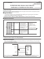
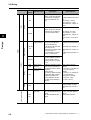
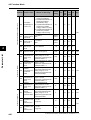
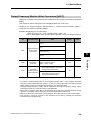
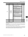
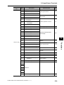
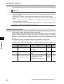
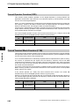
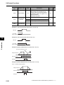
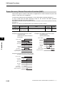
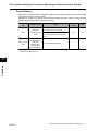
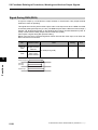
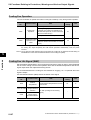
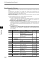
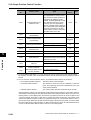
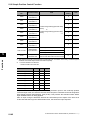
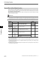
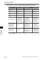
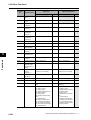
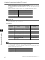
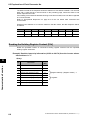
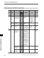
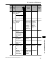
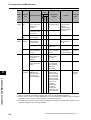
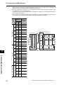
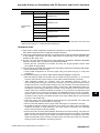
1. Relevant location: Page 2-8, Digital Specifications in Control Circuit Terminals
Contact
Input
Digital
■ Additional Information
S7/EB
S6
S5/TH
S4/GS2
S3/GS1
S2
S1
Multi-function
input terminal
Select 7 functions from
among 59, and allocate
them to terminals S1
through S7/EB. Both sink
and source logics are
supported. For details, refer
to "Connection to
Programmable Controller
(PLC)" on page 2-22.
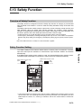
Safety input
Enabled when the safety
function selector switch is
turned ON. For details, refer
to "Safety Function" on
page 5-170.
S4/GS2
S3/GS1
Voltage between each
input and PSC
ON voltage: 18 V min.
OFF voltage: 3 V max.
Allowable max. voltage: 27
VDC
Load current: 5 mA (at 24
V)
Internal resistance: 4.7 kΩ
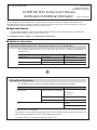
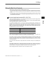
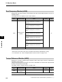
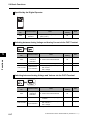
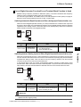
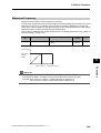
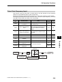
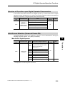
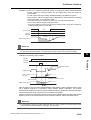
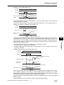
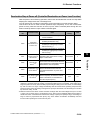
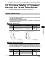
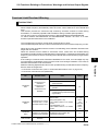
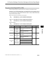
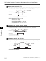
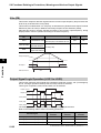
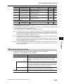
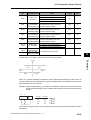
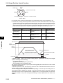
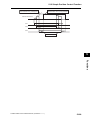
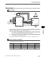
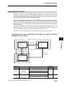
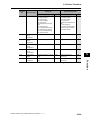
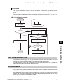
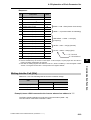
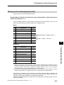
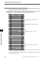
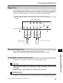
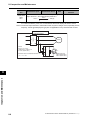
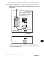
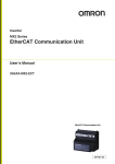
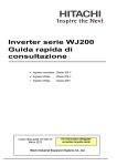
2. Relevant location: Page 5-172, Wiring Example
■ Additional Information
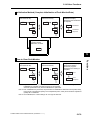
When using the EDM function, we recommend that you use the following wiring example to
connect to the Safety Controller.
G9SP-series Safety Controller
MX2-series Inverter
GS2
Safety Output
GS1
Safety Output
V1
24V DC ± 15%
0V
PSC
G0
PC
Test Output
EDM
Safety Input
When connecting to more that one Safety Controller or when connecting to other safety devices, use the
above diagram for reference and make sure that the devices are used within their operating ratings.
To: All Customers
August 2010
OMRON Corporation
Automation Systems HQ
SYSDRIVE MX2 Series User's Manual
Notification of Additional Information
Cat. No. I570-E1-02
Thank you for supporting OMRON and OMRON products.
The SYSDRIVE MX2 Series Multi-function Compact Inverters have been certified for additional international safety
standards. Please mark your manuals so that the corrections are noted on the pages concerned, and then securely add
any required pages from this Notification to the rear of the manual.
■ Applicable Manual
• This Notification applies to the SYSDRIVE MX2 Series Multi-function Compact Inverter User's Manual
that was issued in March 2010 (Cat. No. I570-E1-02).
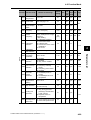
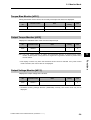
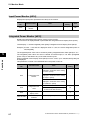
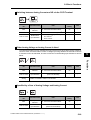
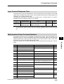
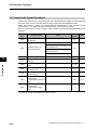
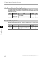
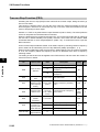
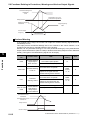
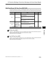
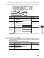
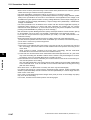
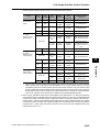
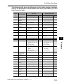
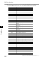
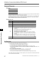
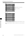
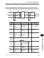
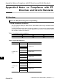
1. Relevant location: Page 1-2, International Standards
■ Additional Information
International Standards (EC Directives and UL/cUL Standards)
The 3G3MX2 Inverter meets the EC Directives and UL/cUL standard requirements for
worldwide use.
Classification
EC Directives
Applicable standard
EMC directive
EN61800-3: 2004
Low-voltage directive
EN61800-5-1: 2003
UL/cUL Standards
UL508C
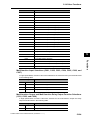
International Standards
The 3G3MX2-series Inverters meet the following international standards
Classification
EC Directives
Applicable standard
Machinery Directive 2006/94/EC EN ISO13849-1:2008 PLd
EN 61800-5-2
EN 60204-1
Low-voltage directive
EN 61800-5-1
EMC directive
EN 61800-3
UL
UL508C
CSA-C22.2 No. 14
Safety functions are supported.
The 3G3MX2-series Inverters meet requirements for IEC 60204-1 Stop Category 0 operation and
ISO 13849-1 Performance Level PLd of the Machinery Directive.
For details, refer to 5-13 Safety Function on page 5-170.
Read and Understand this Manual
Read and Understand this Manual
Please read and understand this manual before using the product. Please consult your
OMRON representative if you have any questions or comments.
Warranty and Limitations of Liability
WARRANTY
OMRON's exclusive warranty is that the products are free from defects in materials and workmanship
for a period of one year (or other period if specified) from date of sale by OMRON.
OMRON MAKES NO WARRANTY OR REPRESENTATION, EXPRESS OR IMPLIED, REGARDING
NON-INFRINGEMENT, MERCHANTABILITY, OR FITNESS FOR PARTICULAR PURPOSE OF THE
PRODUCTS. ANY BUYER OR USER ACKNOWLEDGES THAT THE BUYER OR USER ALONE HAS
DETERMINED THAT THE PRODUCTS WILL SUITABLY MEET THE REQUIREMENTS OF THEIR
INTENDED USE. OMRON DISCLAIMS ALL OTHER WARRANTIES, EXPRESS OR IMPLIED.
LIMITATIONS OF LIABILITY
OMRON SHALL NOT BE RESPONSIBLE FOR SPECIAL, INDIRECT, OR CONSEQUENTIAL
DAMAGES, LOSS OF PROFITS OR COMMERCIAL LOSS IN ANY WAY CONNECTED WITH THE
PRODUCTS, WHETHER SUCH CLAIM IS BASED ON CONTRACT, WARRANTY, NEGLIGENCE, OR
STRICT LIABILITY.
In no event shall the responsibility of OMRON for any act exceed the individual price of the product on
which liability is asserted.
IN NO EVENT SHALL OMRON BE RESPONSIBLE FOR WARRANTY, REPAIR, OR OTHER CLAIMS
REGARDING THE PRODUCTS UNLESS OMRON'S ANALYSIS CONFIRMS THAT THE PRODUCTS
WERE PROPERLY HANDLED, STORED, INSTALLED, AND MAINTAINED AND NOT SUBJECT TO
CONTAMINATION, ABUSE, MISUSE, OR INAPPROPRIATE MODIFICATION OR REPAIR.
2
SYSDRIVE MX2 Series USER'S MANUAL (3G3MX2-A@@@@)
Read and Understand this Manual
Application Considerations
SUITABILITY FOR USE
OMRON shall not be responsible for conformity with any standards, codes, or regulations that apply to
the combination of products in the customer's application or use of the products.
At the customer's request, OMRON will provide applicable third party certification documents identifying
ratings and limitations of use that apply to the products. This information by itself is not sufficient for a
complete determination of the suitability of the products in combination with the end product, machine,
system, or other application or use.
The following are some examples of applications for which particular attention must be given. This is not
intended to be an exhaustive list of all possible uses of the products, nor is it intended to imply that the
uses listed may be suitable for the products:
• Outdoor use, uses involving potential chemical contamination or electrical interference, or conditions
or uses not described in this manual.
• Nuclear energy control systems, combustion systems, railroad systems, aviation systems, medical
equipment, amusement machines, vehicles, safety equipment, and installations subject to separate
industry or government regulations.
• Systems, machines, and equipment that could present a risk to life or property.
Please know and observe all prohibitions of use applicable to the products.
NEVER USE THE PRODUCTS FOR AN APPLICATION INVOLVING SERIOUS RISK TO LIFE OR
PROPERTY WITHOUT ENSURING THAT THE SYSTEM AS A WHOLE HAS BEEN DESIGNED TO
ADDRESS THE RISKS, AND THAT THE OMRON PRODUCTS ARE PROPERLY RATED AND
INSTALLED FOR THE INTENDED USE WITHIN THE OVERALL EQUIPMENT OR SYSTEM.
PROGRAMMABLE PRODUCTS
OMRON shall not be responsible for the user's programming of a programmable product, or any
consequence thereof.
SYSDRIVE MX2 Series USER'S MANUAL (3G3MX2-A@@@@)
3
Read and Understand this Manual
Disclaimers
CHANGE IN SPECIFICATIONS
Product specifications and accessories may be changed at any time based on improvements and other
reasons.
It is our practice to change model numbers when published ratings or features are changed, or when
significant construction changes are made. However, some specifications of the products may be
changed without any notice. When in doubt, special model numbers may be assigned to fix or establish
key specifications for your application on your request. Please consult with your OMRON representative
at any time to confirm actual specifications of purchased products.
DIMENSIONS AND WEIGHTS
Dimensions and weights are nominal and are not to be used for manufacturing purposes, even when
tolerances are shown.
PERFORMANCE DATA
Performance data given in this manual is provided as a guide for the user in determining suitability and
does not constitute a warranty. It may represent the result of OMRON's test conditions, and the users
must correlate it to actual application requirements. Actual performance is subject to the OMRON
Warranty and Limitations of Liability.
ERRORS AND OMISSIONS
The information in this manual has been carefully checked and is believed to be accurate; however, no
responsibility is assumed for clerical, typographical, or proofreading errors, or omissions.
4
SYSDRIVE MX2 Series USER'S MANUAL (3G3MX2-A@@@@)
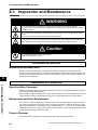
Safety Precautions
Safety Precautions
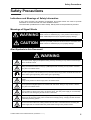
Indications and Meanings of Safety Information
In this user's manual, the following precautions and signal words are used to provide
information to ensure the safe use of the 3G3MX2 Inverter.
The information provided here is vital to safety. Strictly observe the precautions provided.
Meanings of Signal Words
WARNING
Indicates a potentially hazardous situation which, if not avoided, will
result in minor or moderate injury, or may result in serious injury or
death. Additionally there may be significant property damage.
CAUTION
Indicates a potentially hazardous situation which, if not avoided, may
result in minor or moderate injury or in property damage.
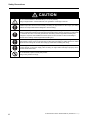
Alert Symbols in this Document
WARNING
Turn off the power supply and implement wiring correctly. Not doing so may result in a serious injury
due to an electric shock.
Wiring work must be carried out only by qualified personnel. Not doing so may result in a serious
injury due to an electric shock.
Be sure to ground the unit. Not doing so may result in a serious injury due to an electric shock or fire.
(200 V class: type-D grounding, 400 V class: type-C grounding)
Do not remove the terminal block cover during the power supply and 10 minutes after the power
shutoff.
Doing so may result in a serious injury due to an electric shock.
Do not operate the Digital Operator or switches with wet hands. Doing so may result in a serious
injury due to an electric shock.
Inspection of the Inverter must be conducted after the power supply has been turned off. Not doing
so may result in a serious injury due to an electric shock. The main power supply is not necessarily
shut off even if the emergency shutoff function is activated.
Do not change wiring, slide switches, or optional devices while power is being supplied.
Always turn off the power supply to the Inverter before changing wiring, changing the slide switches,
or attaching/removing options.
Do not touch the Inverter fins, braking resistors and the motor, which become too hot during the
power supply and for some time after the power shutoff. Doing so may result in a burn.
SYSDRIVE MX2 Series USER'S MANUAL (3G3MX2-A@@@@)
5
Safety Precautions
CAUTION
Do not connect resistors to the terminals (+1, P/+2, N/−) directly.
Doing so might result in a small-scale fire, heat generation or damage to the unit.
Install a stop motion device to ensure safety. Not doing so might result in a minor injury. (A holding
brake is not a stop motion device designed to ensure safety.)
Be sure to use a specified type of braking resistor/regenerative braking unit. In case of a braking
resistor, install a thermal relay that monitors the temperature of the resistor. Not doing so might result
in a moderate burn due to the heat generated in the braking resistor/regenerative braking unit.
Configure a sequence that enables the Inverter power to turn off when unusual overheating is
detected in the braking resistor/regenerative braking unit.
The Inverter has high voltage parts inside which, if short-circuited, might cause damage to itself or
other property. Place covers on the openings or take other precautions to make sure that no metal
objects such as cutting bits or lead wire scraps go inside when installing and wiring.
Take safety precautions such as setting up a molded-case circuit breaker (MCCB) that matches the
Inverter capacity on the power supply side. Not doing so might result in damage to property due to
the short circuit of the load.
Do not dismantle, repair or modify this product.
Doing so may result in an injury.
6
SYSDRIVE MX2 Series USER'S MANUAL (3G3MX2-A@@@@)
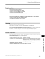
Precautions for Safe Use
Precautions for Safe Use
Installation and Storage
Do not store or use the product in the following places.
Locations subject to direct sunlight.
Locations subject to ambient temperature exceeding the specifications.
Locations subject to relative humidity exceeding the specifications.
Locations subject to condensation due to severe temperature fluctuations.
Locations subject to corrosive or flammable gases.
Locations subject to exposure to combustibles.
Locations subject to dust (especially iron dust) or salts.
Locations subject to exposure to water, oil, or chemicals.
Locations subject to shock or vibration.
Transporting, Installation, and Wiring
Do not drop or apply strong impact on the product. Doing so may result in damaged parts or
malfunction.
Do not hold by the terminal block cover, but hold by the fins during transportation.
Do not connect an AC power supply voltage to the control input/output terminals. Doing so may
result in damage to the product.
Be sure to tighten the screws on the terminal block securely.
Wiring work must be done after installing the unit body.
Do not connect any load other than a three-phase inductive motor to the U, V, and W output
terminals.
Take sufficient shielding measures when using the product in the following locations. Not doing
so may result in damage to the product.
Locations subject to static electricity or other forms of noise.
Locations subject to strong magnetic fields.
Locations close to power lines.
Main Circuit Power Supply
Confirm that the rated input voltage of the Inverter is the same as AC power supply voltage.
Operation and Adjustment
Be sure to confirm the permissible range of motors and machines before operation because the
Inverter speed can be changed easily from low to high.
Provide a separate holding brake if necessary.
Maintenance and Inspection
Be sure to confirm safety before conducting maintenance, inspection or parts replacement.
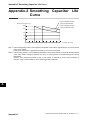
The life of the capacitor depends on ambient temperatures. Refer to the diagram of product life
specified in the manual. When the capacitor stops operating at the end of the product's life, the
Inverter must be replaced.
SYSDRIVE MX2 Series USER'S MANUAL (3G3MX2-A@@@@)
7
Precautions for Correct Use
Precautions for Correct Use
Installation
Mount the product vertically on a wall with the product's longer sides upright.
The material of the wall has to be nonflammable such as a metal plate.
Restart after Trip
Do not come close to the machine when using the Restart During Momentary Power Interruption
function because the machine may abruptly start when stopped by an alarm.
Be sure to confirm the RUN signal is turned off before resetting the alarm because the machine
may abruptly start.
Operation Stop Command
Provide a separate emergency stop switch because the STOP key on the Digital Operator is valid
only when function settings are performed.
When checking a signal during the power supply and the voltage is erroneously applied to the
control input terminals, the motor may start abruptly. Be sure to confirm safety before checking a
signal.
Maintenance and Parts Replacement
The Inverter consists of many parts, and these parts must operate properly in order to make full
use of the designed functions of the Inverter. Among the electronic components, there are some
that require maintenance depending on their usage conditions. In order to keep the Inverter
operating normally over a long period of time, it is necessary to perform periodic inspections and
replace parts according to their service life.
Product Disposal
Comply with the local ordinance and regulations when disposing of the product.
8
SYSDRIVE MX2 Series USER'S MANUAL (3G3MX2-A@@@@)
Precautions for Correct Use
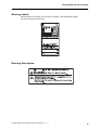
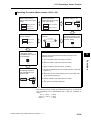
Warning Labels
Warning labels are located on the Inverter as shown in the following illustration.
Be sure to follow the instructions.
Warning Description
SYSDRIVE MX2 Series USER'S MANUAL (3G3MX2-A@@@@)
9
Checking Before Unpacking
Checking Before Unpacking
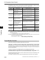
Checking the Product
On delivery, be sure to check that the delivered product is the Inverter 3G3MX2 model that you
ordered.
Should you find any problems with the product, immediately contact your nearest local sales
representative or OMRON sales office.
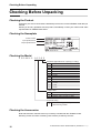
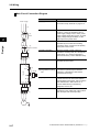
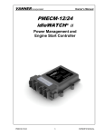
Checking the Nameplate
Inverter model
Input specifications
Output specifications
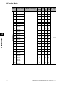
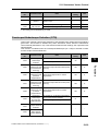
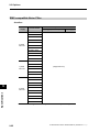
Checking the Model
3 G 3 M X 2 - A 2 0 5 5
Maximum applicable motor capacity (CT rating)
001
002
004
007
015
022
030
037
040
055
075
110
150
0.1 kW
0.2 kW
0.4 kW
0.75 kW
1.5 kW
2.2 kW
3.0 kW
3.7 kW
4.0 kW
5.5 kW
7.5 kW
11 kW
15 kW
Voltage class
B
2
4
1-phase 200 V AC (200 V class)
3-phase 200 V AC (200 V class)
3-phase 400 V AC (400 V class)
Enclosure rating
A
Panel-mounting (IP10 min.) or closed
wall-mounting models
Checking the Accessories
Note that Instruction manual is the only accessory included with the 3G3MX2 model.
Mounting screws and other necessary parts must be provided by the user.
10
SYSDRIVE MX2 Series USER'S MANUAL (3G3MX2-A@@@@)
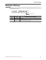
Revision History
Revision History
A manual revision code appears as a suffix to the catalog number located at the lower left of
the front and back covers.
Cat.No.
I570-E1-02
Revision code
Revision
code
01
02
Revision
date
Changes and revision pages
September 2009 First printing
March 2010
Revised information on the simple position control function and
revised/corrected manual contents.
SYSDRIVE MX2 Series USER'S MANUAL (3G3MX2-A@@@@)
11
About This Manual
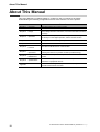
About This Manual
This User's Manual is compiled chapter by chapter for user's convenience as follows.
Understanding the following configuration ensures more effective use of the product.
Overview
Chapter 1
Overview
Describes features and names of parts.
Chapter 2
Design
Provides external dimensions, installation dimensions, peripheral
device design/selection instructions, and other information necessary
for design.
Chapter 3
Operation
Describes names of parts, the Inverter's operations, including how to
use the keys on the Digital Operator, and the monitor function.
Chapter 4
Parameter List
List of parameters set via Digital Operator.
Chapter 5
Functions
Describes the functions of the Inverter.
Chapter 6
Communication
Function
Describes the Modbus-RTU communication.
Chapter 7
Maintenance
Operations
Describes the causes and their countermeasures if the Inverter fails,
including the solutions to possible troubles (troubleshooting).
Chapter 8
Inspection and
Maintenance
Describes items for periodical inspection and/or maintenance for the
Inverter.
Chapter 9
Specifications
Provides Inverter specifications, as well as the specifications and
dimensions of peripheral devices.
Appendix
12
Describes the derating chart, capacitor life curve, compliance with
international standards and index.
SYSDRIVE MX2 Series USER'S MANUAL (3G3MX2-A@@@@)
Contents
Introduction ......................................................................................
1
Read and Understand this Manual ..................................................
2
Safety Precautions...........................................................................
5
Precautions for Safe Use.................................................................
7
Precautions for Correct Use ............................................................
8
Checking Before Unpacking ............................................................
10
Revision History...............................................................................
11
About This Manual...........................................................................
12
Chapter1 Overview
1-1
1-2
Functions......................................................................................................1-1
Appearance and Names of Parts .................................................................1-4
Chapter2 Design
2-1
2-2
Installation ....................................................................................................2-1
Wiring ...........................................................................................................2-6
Chapter3 Operation
3-1
3-2
3-3
3-4
Name of Parts of the Digital Operator ..........................................................3-1
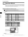
Operation Method.........................................................................................3-7
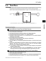
Test Run.....................................................................................................3-10
Tripping ......................................................................................................3-12
Chapter4 Parameter List
4-1
4-2
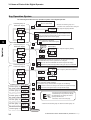
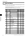
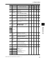
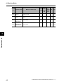
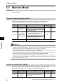
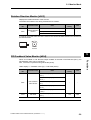
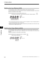
Monitor Mode ...............................................................................................4-1
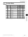
Function Mode..............................................................................................4-4
Chapter5 Functions
5-1
5-2
5-3
5-4
5-5
5-6
5-7
5-8
5-9
5-10
5-11
5-12
5-13
5-14
14
Monitor Mode ...............................................................................................5-1
Basic Functions ..........................................................................................5-13
Input/Output Terminals...............................................................................5-29
Analog Signal .............................................................................................5-37
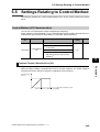
Settings Relating to Control Method...........................................................5-46
Operation Functions ...................................................................................5-56
Digital Operator/Operation Functions.........................................................5-84
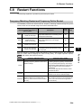
Restart Functions .......................................................................................5-94
Functions Relating to Protections, Warnings
and Various Output Signals......................................................................5-110
Brake Settings ..........................................................................................5-135
Sensorless Vector Control........................................................................5-144
Simple Position Control Function .............................................................5-158
Safety Function ........................................................................................5-170
Other Functions........................................................................................5-174
SYSDRIVE MX2 Series USER'S MANUAL (3G3MX2-A@@@@)
Contents
Chapter6 Communication Function
6-1
6-2
6-3
6-4
6-5
6-6
6-7
6-8
Communication Specifications..................................................................... 6-1
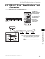
RS-485 Port Specifications and Connection................................................ 6-2
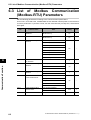
List of Modbus Communication (Modbus-RTU) Parameters ....................... 6-3
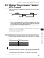
Modbus Communication (Modbus-RTU) Protocol ....................................... 6-4
Explanation of Each Parameter No.............................................................. 6-8
To Save the Change to the Holding Register (Enter Command)............... 6-19
Co-Inverter Communication ....................................................................... 6-22
List of Modbus Communication (Modbus-RTU) Data ................................ 6-27
Chapter7 Maintenance Operations
7-1
7-2
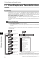
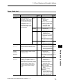
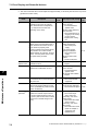
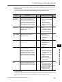
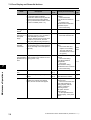
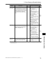
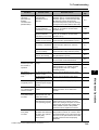
Error Display and Remedial Actions ............................................................ 7-1
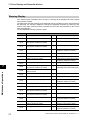
Troubleshooting ......................................................................................... 7-10
Chapter8 Inspection and Maintenance
8-1
Inspection and Maintenance ........................................................................ 8-1
Chapter9 Specifications
9-1
9-2
9-3
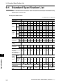
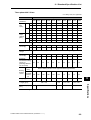
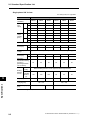
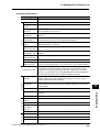
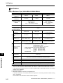
Standard Specification List .......................................................................... 9-1
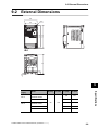
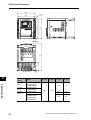
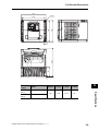
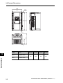
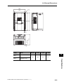
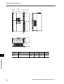
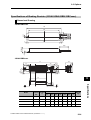
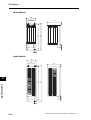
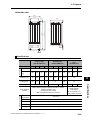
External Dimensions .................................................................................... 9-6
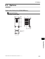
Options....................................................................................................... 9-12
Appendices
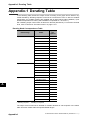
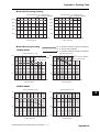
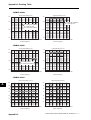
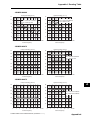
Appendix-1
Appendix-2
Appendix-3
Appendix-4
Derating Table .................................................................................App-1
Smoothing Capacitor Life Curve ......................................................App-7
Life Alarm Output .............................................................................App-8
Notes on Compliance with EC Directives and UL/cUL Standards ...App-9
INDEX
SYSDRIVE MX2 Series USER'S MANUAL (3G3MX2-A@@@@)
15
Overview
1
Describes the features, operating procedures, performance specifications and
other aspects of this Unit.
1-1
Functions............................................................................... 1-1
3G3MX2 Inverter Models ................................................................ 1-1
International Standards (EC Directives and UL/cUL Standards) .... 1-2
High-performance, Multi-function Compact Inverter Supporting
Wide-ranging Applications .............................................................. 1-2
1-2
Appearance and Names of Parts......................................... 1-4
SYSDRIVE MX2 Series USER'S MANUAL (3G3MX2-A@@@@)
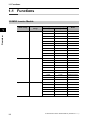
1-1 Functions
1-1 Functions
3G3MX2 Inverter Models
Rated voltage
1
IP20
Overview
3-phase 200 VAC
Enclosure
ratings
3-phase 400 VAC
1-phase 200 V AC
1-1
IP20
IP20
Max. applicable motor capacity
Model
CT: Heavy load
VT: Light load
0.1kW
0.2 kW
3G3MX2-A2001
0.2 kW
0.4 kW
3G3MX2-A2002
0.4 kW
0.75 kW
3G3MX2-A2004
0.75 kW
1.1 kW
3G3MX2-A2007
1.5 kW
2.2 kW
3G3MX2-A2015
2.2 kW
3.0 kW
3G3MX2-A2022
3.7 kW
5.5 kW
3G3MX2-A2037
5.5 kW
7.5 kW
3G3MX2-A2055
7.5 kW
11 kW
3G3MX2-A2075
11 kW
15 kW
3G3MX2-A2110
15 kW
18.5 kW
3G3MX2-A2150
0.4 kW
0.75 kW
3G3MX2-A4004
0.75 kW
1.5 kW
3G3MX2-A4007
1.5 kW
2.2 kW
3G3MX2-A4015
2.2 kW
3.0 kW
3G3MX2-A4022
3.0 kW
4.0 kW
3G3MX2-A4030
4.0 kW
5.5 kW
3G3MX2-A4040
5.5 kW
7.5 kW
3G3MX2-A4055
7.5 kW
11 kW
3G3MX2-A4075
11 kW
15 kW
3G3MX2-A4110
15 kW
18.5 kW
3G3MX2-A4150
0.1 kW
0.2 kW
3G3MX2-AB001
0.2 kW
0.4 kW
3G3MX2-AB002
0.4 kW
0.55 kW
3G3MX2-AB004
0.75 kW
1.1 kW
3G3MX2-AB007
1.5 kW
2.2 kW
3G3MX2-AB015
2.2 kW
3.0 kW
3G3MX2-AB022
SYSDRIVE MX2 Series USER'S MANUAL (3G3MX2-A@@@@)
1-1 Functions
International Standards (EC Directives and UL/cUL Standards)
The 3G3MX2 Inverter meets the EC Directives and UL/cUL standard requirements for
worldwide use.
Classification
EC Directives
Applicable standard
EMC directive
EN61800-3: 2004
Low-voltage directive
EN61800-5-1: 2003
UL/cUL Standards
1
UL508C
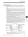
Powerful Torque Ideal for a Variety of Applications
High starting torque
With the sensorless vector control and auto-tuning functions, this Unit ensures high starting
torque of 200% at 0.5 Hz.
Note. The frame may have to be raised depending on the condition.
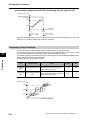
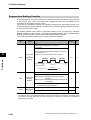
Overload limit/Overcurrent Suppression function
(1) The Inverter monitors the motor current during acceleration or constant speed operation in
order to lower output frequency automatically.
(2) This function suppresses significant change in current caused by rapid acceleration, etc.
Acceleration will be suppressed temporarily if the output current reaches approx. 180% of
the rated current during acceleration.
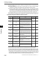
Various Applications
Safety Function
Conforming to stop category 0 under IEC60204-1 and the ISO13849-1: 2006 (PLd) standard
(certification pending)
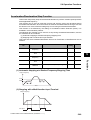
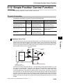
Simple Position Control Function
(1) Comes standard with the pulse input functions.
(2) Supporting simple positioning to a maximum of 8 points by setting the position command,
speed reference and acceleration/deceleration time to parameters.
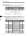
Comes Standard with RS-485 (Modbus-RTU)
(1) Comes standard with the Modbus-RTU communication function to communicate with, and
also read/write various parameters from/to, the host equipment.
Broadcasting from the host equipment is also supported.
(2) Transfer Speed: Supporting speeds up to 115.2 kbps
(3) Co-inverter communication is also supported.
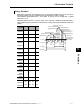
Side-by-Side (Zero Clearance) Installation
Since the Inverter can be installed with its right or left face contacting a wall or other structure,
the installation space can be reduced.
SYSDRIVE MX2 Series USER'S MANUAL (3G3MX2-A@@@@)
1-2
Overview
High-performance, Multi-function Compact Inverter Supporting Wide-ranging Applications
1-1 Functions
Note. The carrier frequency, etc. must be derated depending on the model.
Password Function
Comes with the password function to prevent reading or changing of parameters without
proper access privileges.
Overview
1
1-3
SYSDRIVE MX2 Series USER'S MANUAL (3G3MX2-A@@@@)
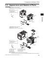
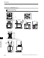
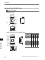
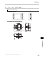
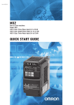
1-2 Appearance and Names of Parts
1-2 Appearance and Names of Parts
1-phase 200 V 0.1, 0.2, 0.4 kW
3-phase 200 V 0.1, 0.2, 0.4, 0.75 kW
Even if the W × H
dimension is the same, the
D dimension for the
cooling fin varies
depending on the capacity.
1
H
(3)
D
Overview
W
(5)
(6)
(4)
(7)
1-phase 200 V 0.75, 1.5, 2.2 kW
3-phase 200 V 1.5, 2.2 kW
3-phase 400 V 0.4, 0.75, 1.5, 2.2, 3.0 kW
(1)
(2)
(3)
Even if the W × H
dimension is the same, the
D dimension for the
cooling fin varies
depending on the capacity.
(5)
(4)
H
(6)
D
(7)
W
(1) Cooling fan cover
(2) Cooling fan
(3) Cooling fin
(4) Main housing
(5) Terminal block cover
(6) Optional board cover
(7) Backing plate
Note: • 3-phase 200 V/0.75 kW models come with a cooling fan.
• 1-phase 200 V/0.75 kW models and 3-phase 400 V/0.4 kW/0.75 kW models do not come with a cooling fan.
SYSDRIVE MX2 Series USER'S MANUAL (3G3MX2-A@@@@)
1-4
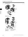
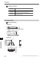
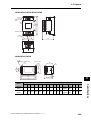
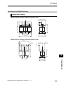
1-2 Appearance and Names of Parts
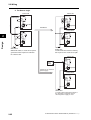
3-phase 200 V 3.7 kW
3-phase 400V 4.0 kW
(1)
(2)
(3)
1
Overview
(5)
(6)
(4)
(7)
3-phase 200 V 5.5, 7.5 kW
3-phase 400 V 5.5, 7.5 kW
(1)
(2)
(3)
(5)
(6)
(4)
(7)
(1) Cooling fan cover
(2) Cooling fan
(3) Cooling fin
(4) Main housing
1-5
(5) Terminal block cover
(6) Optional board cover
(7) Backing plate
SYSDRIVE MX2 Series USER'S MANUAL (3G3MX2-A@@@@)
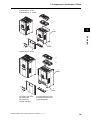
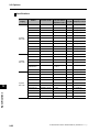
1-2 Appearance and Names of Parts
3-phase 200 V 11 kW
3-phase 400 V 11, 15 kW
(1)
(2)
1
(3)
Overview
(5)
(6)
(4)
(7)
3-phase 200 V 15 kW
(1)
(2)
(3)
(5)
(6)
(4)
(7)
(1) Cooling fan cover
(2) Cooling fan
(3) Cooling fin
(4) Main housing
(5) Terminal block cover
(6) Optional board cover
(7) Backing plate
SYSDRIVE MX2 Series USER'S MANUAL (3G3MX2-A@@@@)
1-6
Design
Describes the name and function of each part, installation method, wiring method,
etc.
2-1
Installation ............................................................................. 2-1
Precautions for Safe Use ................................................................ 2-1
Precautions for Correct Use............................................................ 2-2
Installation Environment.................................................................. 2-2
Backing Plate .................................................................................. 2-3
Installation/Removal Method of the Terminal Block Cover ............. 2-4
Names of Parts Inside the Terminal Block Cover ........................... 2-5
2-2
Wiring..................................................................................... 2-6
Connection Diagram ....................................................................... 2-6
Wiring the Main Circuit Terminals ................................................. 2-10
Wiring Control Circuit Terminals ................................................... 2-18
Connection to Programmable Controller (PLC) ............................ 2-22
SYSDRIVE MX2 Series USER'S MANUAL (3G3MX2-A@@@@)
2
2-1 Installation
2-1 Installation
Precautions for Safe Use
Installation and Storage
Do not store or use the product in the following places.
Locations subject to direct sunlight.
Locations subject to ambient temperature exceeding the specifications.
Locations subject to relative humidity exceeding the specifications.
Locations subject to condensation due to severe temperature fluctuations.
Locations subject to corrosive or flammable gases.
Locations subject to exposure to combustibles.
Locations subject to dust (especially iron dust) or salts.
Locations subject to exposure to water, oil, or chemicals.
Locations subject to shock or vibration.
Design
2
Transportation, Installation, and Wiring
Do not drop or apply any strong impact to the Inverter to avoid damage to the parts and/or
the Inverter.
When transporting the Inverter, hold the fin, not the front cover or terminal block cover.
Do not connect an AC power supply to the control I/O terminals. Doing so may cause damage
to the Inverter.
Be sure to tighten the screws on the terminal block securely. Perform the wiring after
installing the Inverter.
Do not connect any load other than the 3-phase induction motor to the output terminals (U/
T1, V/T2, W/T3) of the Inverter.
Take appropriate and sufficient countermeasures when using the Inverter in the following
locations. Not doing so may result in damage to the Inverter.
Locations subject to static electricity or other forms of noise.
Locations subject to strong electromagnetic fields.
Locations close to power supplies.
Main Circuit Power Supply
Confirm that the rated input voltage of the Inverter matches the AC power supply voltage.
2-1
SYSDRIVE MX2 Series USER'S MANUAL (3G3MX2-A@@@@)
2-1 Installation
Precautions for Correct Use
Installation
Install the Inverter vertically on a wall.
Install the Inverter on a nonflammable wall surface material, like metal.
2
Design
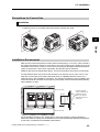
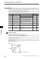
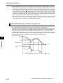
Installation Environment
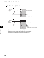
Make sure the ambient temperature remains within the rated range (−10 to 50°C). Take note that if
the ambient temperature reaches or exceeds 40°C, the carrier frequency and output current must
be derated. If the Inverter is used in an environment exceeding the allowable operating temperature
range, the product life of the Inverter (specifically, the capacitor) will be shortened.
Measure and check the temperature approx. 5 cm from the bottom center of the Inverter body.
Provide sufficient space around the Inverter because it can become very hot (up to 150°C or so).
Keep the Inverter away from heating elements (such as a Braking Resistor, reactor, etc.).
Although side-by-side installation is possible. The ambient temperature of the installation site
must not exceed 40°C and the carrier frequency and output current must be derated if side-byside installation is used.
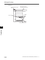
100 mm or more
Provide sufficient
space so that the top
and bottom wiring
ducts, etc. will not
obstruct the flows of
cooling air.
Inverter
Air flow
Wall
50 mm or more
100 mm or more
Do not install the Inverter in hot, humid sites or other sites subject to frequent bedewing.
Make sure that the humidity in the installation site is within the allowable operating range (20%
to 90% RH), as defined in the standard specifications.
SYSDRIVE MX2 Series USER'S MANUAL (3G3MX2-A@@@@)
2-2
2-1 Installation
In particular, make sure that the installation site is free from condensation. If condensed water
adheres to the Inverter's internal parts, the electronic components may short-circuit, causing
failure of the Inverter. In addition to avoiding condensation, avoid installing the Inverter under
direct sunlight.
Avoid an environment where the Inverter may be exposed to dust, gases (corrosive, explosive,
and/or flammable), grinding fluid mist, or salt. If a foreign object (e.g. dust) enters the Inverter,
it could result in failure of the Inverter. If using the Inverter in a dusty place, take appropriate
measures. (For example, place the Inverter in a closed panel.)
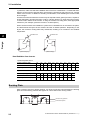
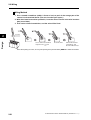
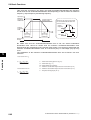
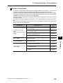
When several Inverters are installed in a panel and a ventilation fan is mounted in the panel,
be careful about the layout of the Inverters and the air intake apertures. Depending on the
layout, the Inverter's cooling effect may deteriorate, resulting in an increase in the ambient
temperature.
Ventilation fan
Design
2
Ventilation fan
Inverter
Inverter
(Good example)
(Bad example)
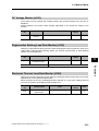
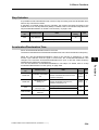
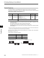
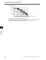
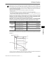
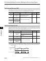
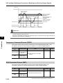
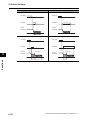
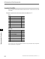
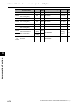
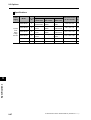
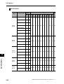
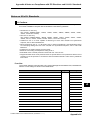
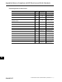
Heat Radiation from Inverter
1-phase/3-phase 200 V
Inverter capacity (kW)
0.1
0.2
0.4
0.75
1.5
2.2
3.7
5.5
7.5
11
15
Load with 100% loss (W)
12
22
30
48
79
104
154
229
313
458
625
89.5
90
93
94
95
95.5
96
96
96
96
96
Inverter capacity (kW)
0.4
0.75
1.5
2.2
3.0
4.0
5.5
7.5
11
15
Load with 100% loss (W)
35
56
96
116
125
167
229
296
411
528
Efficiency at rated output (%)
92
93
94
95
96
96
96
96.2 96.4 96.6
Efficiency at rated output (%)
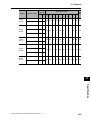
3-phase 400 V
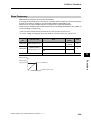
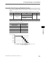
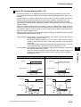
Backing Plate
With a model of 5.5 kW or higher capacity, cut off the connection points between the backing
plate and unnecessary portions with nippers or a wire cutter when running cables.
Unnecessary portions
Connection points
2-3
SYSDRIVE MX2 Series USER'S MANUAL (3G3MX2-A@@@@)
2-1 Installation
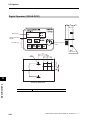
Installation/Removal Method of the Terminal Block Cover
1. Removal method
Loosen the screw(s) (1 or 2
locations) securing the
terminal block cover.
While pressing the bottom of the
terminal block cover in the direction
of the arrow, pull the terminal block
cover downward to remove.
2
Design
While pressing here in the direction
of the arrow, pull the terminal block
cover downward to remove.
The terminal block cover is secured with one screw at the bottom right for 3.0 kW and smaller
models, or with two screws on both sides for 3.7 kW and larger models.
The optional board cover is affixed with screws onto the terminal block cover, but it is not
affixed onto the main unit. Accordingly, the terminal block cover can be removed without
removing the optional board cover.
Optional board cover
8.8.8.8.
8.8.8.8.
Terminal block cover
Terminal block cover screw
(1 location for 3.0 kW and smaller models)
Terminal block cover screw
(2 locations for 3.7 kW and larger models)
2. Installation method
Follow the removal procedure in reverse. Set the top side of the terminal block cover onto the
main unit and push in the cover until you hear a "click" sound.
SYSDRIVE MX2 Series USER'S MANUAL (3G3MX2-A@@@@)
2-4
2-1 Installation
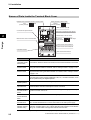
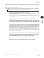
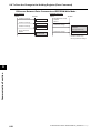
Names of Parts Inside the Terminal Block Cover
Modbus-RTU Termination resistor selector switch
OFF
(Factory default)
ON
Safety function selector switch
Disable
(Factory default)
Enable
USB connector (mini-B)
Connector for optional board
2
Connector for Digital Operator (RJ45)
EDM function selector switch
Design
Multi-function contact terminal block
P1 terminal
(Factory default)
EDM output
Control circuit terminal block A
Control circuit terminal block B
CHARGE indicator
Main circuit terminal block
Name
Description
Modbus-RTU
Termination resistor
selector switch
Use this Terminal Resistor selector switch for RS-485 terminals on the control circuit
terminal block. When this switch is turned ON, the internal 200 Ω Resistor is connected.
Safety function
selector switch
Turn this switch ON when using the safety function. Turn OFF the power before
turning this switch ON/OFF.For details, refer to "Safety Function" on page 5-170.
EDM function
selector switch
Turn this switch ON when using the EDM output of the safety function. Turn OFF
the power before turning this switch ON/OFF. For details, refer to "Safety Function"
on page 5-170.
USB connector
Use this mini-B USB connector to connect a PC.
Even when the Inverter is being operated by a PC, etc., via USB connection, it can
still be operated using the Digital Operator.
Connector for
Digital Operator
Use this connector to connect the Digital Operator.
Connector for
optional board
Use this connector to mount the optional board.
Communications Units and other options can be connected.
Control circuit
terminal blocks A
and B
These terminal blocks are used to connect various digital/analog input and output
signals for inverter control, etc.
Multi-function
contact terminal
block
Use this SPDT contact terminal block for relay outputs.
Main circuit
terminal block
Use this terminal block to connect an output to the motor and Braking Resistor, etc.
Also, use this terminal block to connect the inverter to the main power supply.
CHARGE
indicator (Charge
indicator LED)
This LED indicator is lit if the DC voltage of the main circuit (between terminals P/
+2 and N/−) remains approx. 45 V or above after the power has been cut off. Before
wiring, etc. confirm that the Charge LED indicator is turned OFF.
Note. Refer to Chapter 3 "Operation" for the display and operating controls.
2-5
SYSDRIVE MX2 Series USER'S MANUAL (3G3MX2-A@@@@)
2-2 Wiring
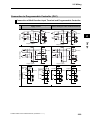
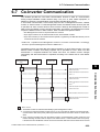
2-2 Wiring
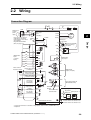
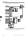
Connection Diagram
AX
MC
Single-phase
3-phase
power
supply
MC
OFF
ON
AX
ELB
MC
Shorting
bar
U/T1
M
V/T2
2
3~
W/T3
24 VDC
P24
Motor
Shorting bar
PSC
DC reactor
+1
SC
Design
If any source-logic external
output devices or external
power supply is used, refer to
"Connection to
Programmable Controller
(PLC)" on page 2-22.
R/L1 (L1)*1
S/L2
T/L3 (N)*1
Remove the short bar
when connecting a
DC reactor.
P/+2
SC
RB
Thermistor
S7/EB
N/−
*2
S6
Multi-function
inputs
(7 contact
inputs)
Braking Resistor
MC
S5/TH
MA
S4/GS2
Multi-function
relay output
MB
S3/GS1
S2
P2
S1
Power: 1/4 W min.
Resistance: 2 kΩ min.
10 VDC power supply
(7 mA Max.)
FS
Analog voltage input
0 to 10 V (10 bits)
FV
Analog current input
4 to 20 mA (10 bits)
FI
Pulse input
5 to 24 VDC
(32 kHz Max.)
Analog voltage
output 0 to 10 V
(10 bits)
Pulse output
0 to 10 VDC
(32 kHz Max.)
10 VDC
P1/EDM
PC
Approx.
10 kΩ
Approx.
100 Ω
RS+
SC
Serial communication port
(RS-485/Modbus-RTU)
RP
SC
AM
MP
SC
RS−
Terminal
Resistor
Terminal Resistor
selector switch
When using a Regenerative Braking Unit
Regenerative Braking Resistor *2
Braking Unit *2
RB
SC
SC
Multi-function
outputs (2 outputs)
SC
N/−
Optional board connector
Communications Option
Unit*2
P
P
N RB
Ground to 100 Ω or less for 200-V class
Ground to 100 Ω or less for 400-V class
*1 Connect to terminals L1 and N on a single-phase, 200-V Inverter (3G3MX2-AB@@@).
*2 Optional.
SYSDRIVE MX2 Series USER'S MANUAL (3G3MX2-A@@@@)
2-6
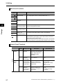
2-2 Wiring
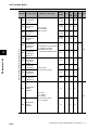
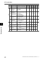
Main Circuit Terminals
Terminal
symbol
R/L1
L1
Terminal name
Description
Main power supply
input terminal
Connect the input AC power supply. Connect to terminals L1 and N
on a single-phase, 200-V Inverter (3G3MX2-AB@@@).
Inverter output
terminal
Connect a 3-phase motor.
DC reactor
connection terminal
Remove the shorting bar between terminals +1 and P/+2, and
connect the optional DC reactor.
Braking Resistor
connection terminal
Connect optional braking resistors. (If a braking torque is required)
N/−
Regenerative
braking unit
connection terminal
Connect optional regenerative braking units. (When braking torque
is required or the built-in braking circuit is not sufficient)
G
Ground terminal
This is a ground terminal. Connect this terminal to the ground.
Provide Class D grounding for 200 V class models, and class C
grounding for 400 V class models.
On 200 V class models of 3.7 kW or below and 400 V class models
of 4.0 kW or below, the ground terminal is located on the cooling fin.
S/L2
T/L3
N
U/T1
V/T2
W/T3
2
+1
P/+2
Design
P/+2
RB
P/+2
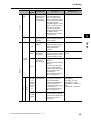
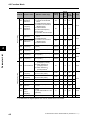
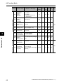
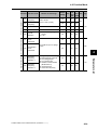
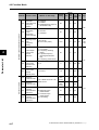
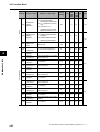
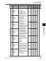
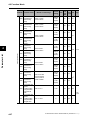
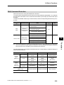
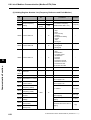
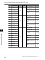
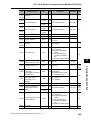
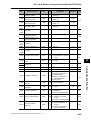
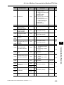
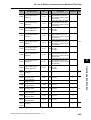
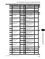
Control Circuit Terminals
Terminal
symbol
Analog
Power
supply
2-7
Frequency
setting
input
Terminal name
Description
Specifications
SC
Input signal
common
This is a common terminal
used by the internal power
supply, digital input and
analog input/output
terminals.
FS
Frequency
reference
power supply
10 VDC power supply for
the FV terminal.
Allowable max. current:
7 mA
FV
Frequency
reference input
terminal (analog
voltage input)
Use this terminal if the
frequency reference is
provided by 0 to 10 VDC
voltage input.
Input impedance
Approx. 10 kΩ
Allowable input voltage
range
−0.3 to +12 VDC
FI
Frequency
reference
terminal (analog
current input)
Use this terminal if the
frequency reference is
provided by 4 to 20 mA
current input.
Input impedance
100 Ω
Allowable input range
0 to 24 mA
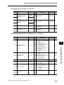
SYSDRIVE MX2 Series USER'S MANUAL (3G3MX2-A@@@@)
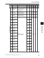
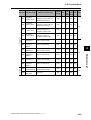
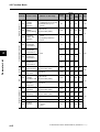
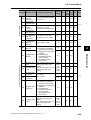
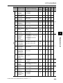
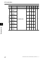
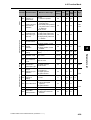
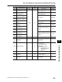
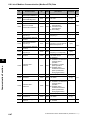
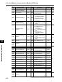
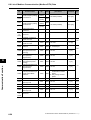
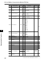
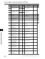
2-2 Wiring
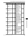
Terminal
symbol
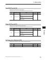
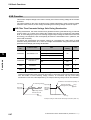
S5/TH
Output
AM
External
thermistor input
(also used as
multi-function
input terminal)
Connect an external
thermistor between the
SCs, to trip the Inverter
when a temperature error
occurs. (The inverter will trip
when the input from
thermistor is approx. 3 kΩ or
higher.) Since this input is
also used as the multifunction input terminal,
setting of C005 is required.
For details, refer to
"Thermistor Trip Function"
on page 5-120.
PTC type
Multi-function
analog output
(voltage)
Specified signals can be
output using voltage signals
of 0 to 10 VDC.
AM
Input signal
common
This is a common terminal
used by the internal power
supply, digital input and
analog input/output
terminals.
Power supply
terminal for
input signal
24 VDC power supply for
contact input signal. This is
used as a common terminal
if the source logic is input.
Power supply
terminal for
input terminal
Sink logic input: Shorted
with P24
Source logic input: Shorted
with SC
To drive the contact input
using an external power
supply, remove the shorting
bar. For details, refer to
"Connection to
Programmable Controller
(PLC)" on page 2-22.
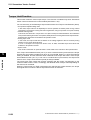
Multi-function
input terminal
Select 7 functions from
among 59, and allocate
them to terminals S1
through S7/EB. Both sink
and source logics are
supported. For details, refer
to "Connection to
Programmable Controller
(PLC)" on page 2-22.
Safety input
Enabled when the safety
function selector switch is
turned ON. For details, refer
to "Safety Function" on
page 5-170.
SC
P24
Power
supply
Contact
Input
Digital
PSC
S7/EB
S6
S5/TH
S4/GS2
S3/GS1
S2
S1
S4/GS2
S3/GS1
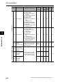
SYSDRIVE MX2 Series USER'S MANUAL (3G3MX2-A@@@@)
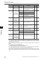
Specifications
2
Design
Description
Analog
Sensor
input
Terminal name
Allowable max. current:
100 mA
Voltage between each
input and PSC
ON voltage: 18 V min.
OFF voltage: 3 V max.
Allowable max. voltage: 27
VDC
Load current: 5 mA (at 24
V)
2-8
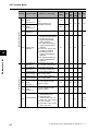
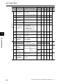
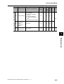
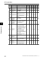
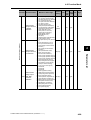
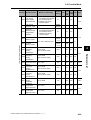
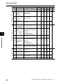
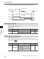
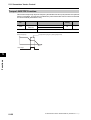
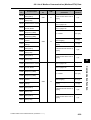
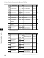
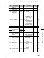
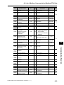
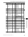
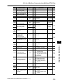
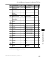
2-2 Wiring
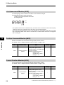
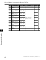
Terminal
symbol
Terminal name
Pulse input-A
Input pulse 32 kHz max.
A pulse input for frequency
setting. (Take note that the
internal circuit is different
from input terminal RP.)
Input pulse 1.8 kHz max.
Multi-function
output terminal
Select 2 functions from
among 43, and allocate
them to terminals P1
through P2. Both sink and
source logics are
supported. For details, refer
to "Connection to
Programmable Controller
(PLC)" on page 2-22.
Open collector output
Between each terminal and
PC
Allowable max. voltage: 27
V
Allowable max. current: 50
mA
Voltage drop when ON: 4 V
max.
Safety monitor
Enabled when the EDM
function selector switch is
ON. For details, refer to
"Safety Function" on page
5-170.
Relay output
terminal
Select the desired functions
from among 43 functions,
and allocate them to these
terminals.
SPDT contact.
The factory default of Relay
Output (MA, MB) Contact
Selection (C036) is NC
contact between MA-MC,
and NO contact between
MB-MC.
Max. contact capacity
MA-MC:
250 VAC, 2 A (resistance)
0.2 A (induction)
MB-MC:
250 VAC, 1 A (resistance)
0.2 A (induction)
Contact min. capacity
100 VAC, 10mA
5 VDC, 100mA
Pulse output
Pulses are output.
Output pulse: 32 kHz max.
Output voltage: 10 VDC
Allowable max. current: 2
mA
Modbus port
(RS-485)
RS-485 port
RS+ RS-485 differential (+)
signal
RS- RS-485 differential (−)
signal
Max. speed: 115.2 kbps
Built-in Terminal Resistor:
200 Ω
Slide switch selection
Pulse
Pulse input-B
S7/EB
Digital
Open collector
Design
2
P1/EDM
P2
Output
P1/EDM
MA
MB
Serial communication
Pulse
Relay
Relay output
common
2-9
MC
MP
RS+
RS−
Specifications
A pulse input for frequency
setting. (Take note that the
internal circuit is different
from input terminals S7/
EB.)
RP
Input
Description
Voltage between input and
SC
ON voltage: 4 V min.
OFF voltage: 1 V max.
Allowable max. voltage: 27
VDC
ON voltage: 18 V min.
OFF voltage: 3 V max.
Allowable max. voltage: 27
VDC
Load current: 5 mA (at 24
V)
SYSDRIVE MX2 Series USER'S MANUAL (3G3MX2-A@@@@)
2-2 Wiring
Wiring the Main Circuit Terminals
Before wiring, make sure that the CHARGE indicator is OFF.
Once the power supply is turned on, the capacitor in the Inverter is charged with high voltage for
a while even after the power supply is turned off and regardless of whether the Inverter is running
or not.
If you are going to change cable connections after the power supply is turned off, wait for at least
10 minutes. Before wiring, check for a residual voltage between terminals "P/+2" and "N/−" with
a circuit tester to ensure safety.
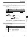
Main power supply input terminals (R/L1, S/L2, T/L3)
2
As a guide for leakage current, if a CV wire is used and routed through a metal pipe, the
leakage current is 30 mA/km. Due to the higher specific inductive capacity of the H-IV wire, the
leakage current increases about eight times. Use a wire with a sensitivity current one-level
higher. The leakage current mentioned here is the effective value of the fundamental wave,
and high-frequency currents are excluded.
Inverter-motor distance
Sensitivity current of earth leakage breaker
100 m max.
30 mA
300 m max.
100 mA
800 m max.
200 mA
When the Inverter protective function is activated, your system may fail or an accident may
occur. Connect a magnetic contactor to turn off the Inverter power supply.
Do not start or stop the Inverter by switching ON/OFF the magnetic contactor provided in the
Inverter power supply input (primary) circuit and output (secondary) circuit. To start or stop the
Inverter via an external signal, use the operation command terminals (FW, RV) on the control
circuit terminal block.
Do not use this Inverter with an input phase loss connection. Doing so may damage the
Inverter.
The Inverter operates with 1-phase input during input phase loss, causing a trip (due to
undervoltage, overcurrent, etc.) or damage to the Inverter. Even if an input phase is open, the
internal capacitor is charged with voltage, and electric shock or injury may occur.
When changing the cable connections, refer to "Precautions for Use."
SYSDRIVE MX2 Series USER'S MANUAL (3G3MX2-A@@@@)
2-10
Design
Use an earth leakage breaker for circuit (wiring) protection between the power supply and the
main power supply terminals (R/L1, S/L2, T/L3).
An earth leakage breaker may malfunction at high frequency. Use an earth leakage breaker
with a large high-frequency sensitive current rating.
2-2 Wiring
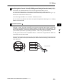
In the following cases, the internal converter module may be damaged:
Imbalance ratio of power supply voltage is 3% or more.
Power supply capacity is ten times or more than the Inverter capacity, and 500 kVA or more.
Rapid change in power supply voltage
Example) When several inverters are connected with a short bus.
When the phase advance capacitor is turned on/off.
Do not turn on the power and then turn it off again more than once every 3 minutes. Doing so
may damage the Inverter.
Inverter output terminal (U/T1, V/T2, W/T3)
For connection of the output terminal, use the compatible cable or a cable with a larger
diameter. Otherwise, the output voltage between the Inverter and the motor may drop.
Particularly during low-frequency output, a voltage drop occurs with the cable, resulting in
motor torque reduction.
2
Design
Do not mount a phase advance capacitor or surge absorber, because these devices may
cause the Inverter to trip or cause damage to the capacitor or surge absorber.
If the cable length exceeds 20 m (particularly, with 400 V class), a surge voltage may be
generated at the motor terminal depending on stray capacitance or inductance of the cable,
causing the motor to burn out.
To suppress surge voltage, we offer a special filter (3G3AX-NFxxx). For details, contact our
authorized dealer.
To connect several motors, provide a thermal relay for each.
The RC value of each thermal relay should be 1.1 times larger than the motor rated current.
The relay may trip earlier depending on the cable length. In this case, connect an AC reactor
to the Inverter output.
DC Reactor Connection Terminal (+1, P/+2)
This terminal is used to connect the optional DC reactor.
By factory default, a shorting bar has been connected between terminals +1 and P/+2. Before
connecting the DC reactor, remove this shorting bar.
The length of the DC reactor connection cable should be 5 m or shorter.
If the DC reactor is not being used, do not remove the shorting bar.
If you remove the shorting bar without connecting the DC reactor, no power is supplied to the
Inverter main circuit, disabling operation.
2-11
SYSDRIVE MX2 Series USER'S MANUAL (3G3MX2-A@@@@)
2-2 Wiring
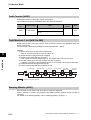
External Braking Resistor Connection Terminal (P/+2, RB)/Regenerative Braking Unit Connection Terminal (P/+2, N/−)
All models in the 3G3MX2 Series have a built-in regenerative braking circuit.
To improve braking capacity, mount the optional braking resistor to this terminal.
Do not mount a resistor whose resistance is lower than the specified value. Doing so may
damage the regenerative braking circuit.
The cable length should be 5 m or shorter. Twist the two wires.
Do not connect any device other than the optional Regenerative Braking Unit or Braking
Resistor to this terminal.
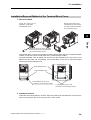
Ground Terminal
For the ground cable, use the compatible cable or a cable with a larger diameter. Make the
cable length as short as possible.
When several Inverters are connected, the ground cable must not be connected across several
Inverters, and must not be looped. Otherwise, the Inverter and surrounding control machines
may malfunction.
Inverter
Inverter
Inverter
Inverter
Inverter
Inverter
SYSDRIVE MX2 Series USER'S MANUAL (3G3MX2-A@@@@)
Your ground bolt
2-12
2
Design
To prevent electric shock, be sure to ground the Inverter and the motor.
The 200 V class should be connected to the ground terminal under Class D grounding
conditions (conventional Class 3 grounding conditions: 100 Ω or less ground resistance), The
400 V class should be connected to the ground terminal under Class C grounding conditions
(conventional special Class 3 grounding conditions: 10 Ω or less ground resistance).
2-2 Wiring
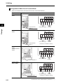
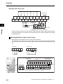
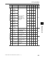
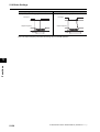
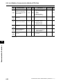
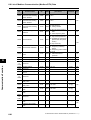
Arrangement of Main Circuit Terminal Block
Open the terminal block cover and wire the main circuit terminal blocks.
Applicable model
Terminal arrangement
3G3MX2-A2001 to
A2007
RB +1 P/+2 N/R/L1 S/L2 T/L3 U/T1 V/T2 W/T3
2
Design
Ground terminal
(M4) × 2
From power supply
3G3MX2-AB001 to
AB004
To motors
RB +1 P/+2 N/L1
N U/T1 V/T2 W/T3
From power supply
Ground terminal
(M4) × 2
To motors
(Connect to L1 and N for 1-phase)
3G3MX2-A2015,
A2022
3G3MX2-A4004 to
A4030
RB +1 P/+2 N/R/L1 S/L2 T/L3 U/T1 V/T2 W/T3
From power supply
To motors
Ground terminal (M4) × 2
3G3MX2-AB007,
AB015, AB022
RB +1 P/+2 N/L1
N U/T1 V/T2 W/T3
From power supply
Ground terminal (M4) × 2
2-13
To motors
(Connect to L1 and N for 1-phase)
SYSDRIVE MX2 Series USER'S MANUAL (3G3MX2-A@@@@)
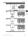
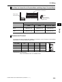
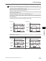
2-2 Wiring
Applicable model
Terminal arrangement
3G3MX2-A2037
3G3MX2-A4040
RB +1 P/+2 N/−
R/L1 S/L2 T/L3 U/T1 V/T2 W/T3
Ground terminal (M4) × 2
3G3MX2-A2055,
A2075
3G3MX2-A4055,
A4075
From power supply
2
R/L1 S/L2 T/L3 U/T1 V/T2 W/T3
From power supply
G
Design
+1 P/+2 N/− RB
3G3MX2-A2110
3G3MX2- A4110 to
A4150
To motors
G
To motors
R/L1 S/L2 T/L3 U/T1 V/T2 W/T3
+1 P/+2 N/− RB
From power supply
G
G
To motors
3G3MX2-A2150
R/L1 S/L2 T/L3 U/T1 V/T2 W/T3
+1 P/+2 N/− RB
From power supply
SYSDRIVE MX2 Series USER'S MANUAL (3G3MX2-A@@@@)
G
G
To motors
2-14
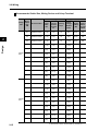
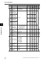
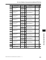
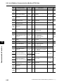
2-2 Wiring
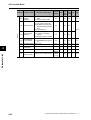
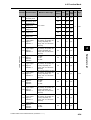
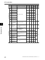
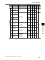
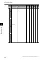
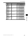
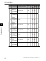
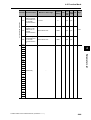
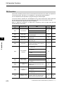
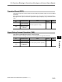
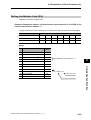
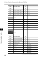
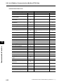
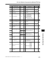
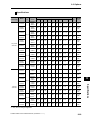
Recommended Cable Size, Wiring Device and Crimp Terminal
Wiring
Voltage
class
Design
2
3-phase
200 V
3-phase
400 V
2-15
Motor
output
(CT)
kW
Inverter model
0.1
Applicable device
Power
cable
mm
Terminalblock screw
size (terminal
block width)
mm
Tightening
torque
Earth
Leakage
Breaker
(ELB)
Fuse size
Magnetic (class J)
contactor
Rated
(MC)
600 V AIC
200kA
3G3MX2-A2001
AWG16
(1.25)
M3.5
(7.6)
1.0
EX30
(5A)
H10C
10A
0.2
3G3MX2-A2002
AWG16
(1.25)
M3.5
(7.6)
1.0
EX30
(5A)
H10C
10A
0.4
3G3MX2-A2004
AWG16
(1.25)
M3.5
(7.6)
1.0
EX30
(10A)
H10C
10A
0.75
3G3MX2-A2007
AWG16
(1.25)
M3.5
(7.6)
1.0
EX30
(10A)
H10C
15A
1.5
3G3MX2-A2015
AWG14
(2.0)
M4
(10)
1.4
EX30
(20A)
H20
15A
2.2
3G3MX2-A2022
AWG12
(3.5)
M4
(10)
1.4
EX30
(20A)
H20
20A
3.7
3G3MX2-A2037
AWG10
(5.5)
M4
(10)
1.4
EX50
(50A)
H25
30A
5.5
3G3MX2-A2055
AWG6
(14)
M5
(13)
3.0
EX60
(60A)
H35
30A
7.5
3G3MX2-A2075
AWG6
(14)
M5
(13)
3.0
EX100
(75A)
H50
40A
11
3G3MX2-A2110
AWG4
(22)
M6
(17.5)
3.9 to 5.1
EX100
(100A)
H65C
60A
15
3G3MX2-A2150
AWG2
(38)
M8
(23)
5.9 to 8.8
EX100
(100A)
H65C
80A
0.4
3G3MX2-A4004
AWG16
(1.25)
M4
(10)
1.4
EX50
(5A)
H10C
10A
0.75
3G3MX2-A4007
AWG16
(1.25)
M4
(10)
1.4
EX50
(10A)
H10C
10A
1.5
3G3MX2-A4015
AWG16
(1.25)
M4
(10)
1.4
EX50
(10A)
H10C
10A
2.2
3G3MX2-A4022
AWG14
(2.0)
M4
(10)
1.4
EX50
(15A)
H20
10A
3.0
3G3MX2-A4030
AWG14
(2.0)
M4
(10)
1.4
EX50
(15A)
H20
15A
4.0
3G3MX2-A4040
AWG12
(3.5)
M4
(10)
1.4
EX50
(20A)
H20
15A
5.5
3G3MX2-A4055
AWG10
(5.5)
M5
(13)
3.0
EX50
(30A)
H25
15A
7.5
3G3MX2-A4075
AWG10
(5.5)
M5
(13)
3.0
EX50
(50A)
H35
20A
11
3G3MX2-A4110
AWG6
(14)
M6
(17.5)
3.9 to 5.1
EX60B
(60A)
H35
30A
15
3G3MX2-A4150
AWG6
(14)
M6
(17.5)
3.9 to 5.1
EX100B
(75A)
H65C
40A
SYSDRIVE MX2 Series USER'S MANUAL (3G3MX2-A@@@@)
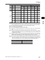
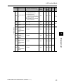
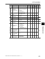
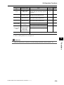
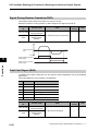
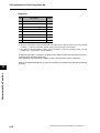
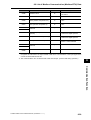
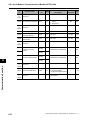
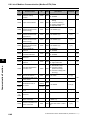
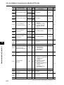
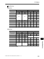
2-2 Wiring
Wiring
Voltage
class
1-phase
200 V
Motor
output
(CT)
kW
Inverter model
0.1
Applicable device
Terminalblock screw
size (terminal
block width)
mm
Tightening
torque
Earth
Leakage
Breaker
(ELB)
Fuse size
Magnetic (class J)
contactor
Rated
(MC)
600 V AIC
200kA
3G3MX2-AB001
AWG16
(1.25)
M3.5
(7.6)
1.0
EX30
(5A)
H10C
10A
0.2
3G3MX2-AB002
AWG16
(1.25)
M3.5
(7.6)
1.0
EX30
(5A)
H10C
10A
0.4
3G3MX2-AB004
AWG16
(1.25)
M3.5
(7.6)
1.0
EX30
(10A)
H10C
10A
0.75
3G3MX2-AB007
AWG12
(3.5)
M4
(10)
1.4
EX30
(15A)
H10C
15A
1.5
3G3MX2-AB015
AWG10
(5.5)
M4
(10)
1.4
EX30
(20A)
H20
20A
2.2
3G3MX2-AB022
AWG10
(5.5)
M4
(10)
1.4
EX30
(20A)
H20
30A
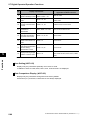
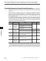
Note 1: Applicable devices assume use of a standard 3-phase, 4-pole motor.
Note 2: Select an applicable circuit breaker by also considering the cutoff capacity. (Use an inverter type.)
Use one circuit breaker for one inverter according to the applications shown in the above table.
Note 3: If the wiring distance exceeds 20 m, the power cable size must be increased.
Note 4: A H-IV wire (75°C) is recommended.
Note 5: Use an earth leakage breaker (ELB) to ensure safety.
Note 6: To meet the UL standards, always insert a UL-standard fuse of class J type on the power supply
side.
Note 7: Use a ground wire with a larger diameter than that of the power cable shown above.
Note 8: Tighten the terminal-block screws with the specified torque. If the screws are not tightened
securely, short-circuiting or fire may occur. Excessive tightening may cause damage to the
terminal block or the Inverter.
Note 9: Choose the sensitivity current of the earth leakage breaker (ELB) depending on the total distance
between the Inverter and the power supply, and the Inverter and the motor. Also, use an earth
leakage breaker of time-delay type. Use of a high-speed type may result in malfunction.
Note 10: If a CV wire is used and routed through a metal pipe, the leakage current becomes 30 mA/km.
Note 11: Due to the higher specific inductive capacity of the IV wire, the leakage current increases about
eight times. Accordingly, use a wire with a sensitivity current of eight times the applicable level
shown in the table below. Also, use a CV wire if the total wiring length exceeds 100 m.
Total wiring length
Sensitivity current (mA)
100 m max.
50
300 m max.
100
SYSDRIVE MX2 Series USER'S MANUAL (3G3MX2-A@@@@)
2-16
2
Design
Power
cable
mm
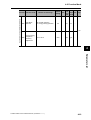
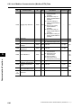
2-2 Wiring
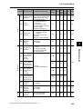
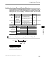
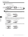
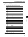
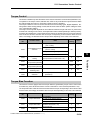
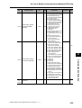
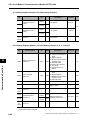
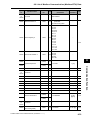
Main Circuit Connection Diagram
Name
Power supply
Function
(1) (2) (3)
Refer to "Recommended Cable Size, Wiring
Device and Crimp Terminal" on page 2-15.
(4) AC reactor
Apply this reactor as a harmonic suppression
measure, or when the imbalance ratio of
power supply voltage is 3% or more, power
supply capacity is 500 kVA or more, or power
supply voltage changes suddenly. It also
helps improve the power factor.
(5) Input noise filter
This noise filter reduces the conducted noise
generated by the Inverter and traveling
through the wires. Connect it to the primary
(input) side of the Inverter.
(6) Radio noise filter
When the Inverter is used, noise may
generate in a nearby radio, etc. through the
power wiring, etc. Use this noise filter to
reduce such noise (= reduce radiated noise).
(7) DC reactor
This reactor suppresses the harmonics
generated by the Inverter.
(8) Braking Resistor
(9) Regenerative braking
unit
Use this Unit to increase the braking torque of
the Inverter to permit frequent ON/OFF
switchings, or decelerate a load whose
inertial moment is large.
(10) Output noise filter
This noise filter is installed between the
Inverter and motor to reduce the radiated
noise emitted from the wires. Use it to reduce
radio interference in radios and TVs, or
prevent malfunctioning of measuring
equipment, sensors, etc.
(11) Radio noise filter
Apply this noise filter to reduce the noise
generating on the output side of the Inverter
(both the input side and output side).
(1)
(2)
ELB
2
Design
(3)
Magnetic contactor
(4)
(5)
(6)
R S T
+1
(7)
Inverter
P/+2
(9) (8)
RB
(8)
N/−
U V W
(10)
(11)
M
2-17
SYSDRIVE MX2 Series USER'S MANUAL (3G3MX2-A@@@@)
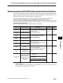
2-2 Wiring
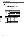
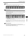
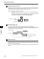
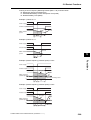
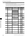
Wiring Control Circuit Terminals
Wiring and Arranging a Control Circuit Terminal Block
Terminals SC and PC are common terminals for input/output signals. They are isolated each
other. Do not short-circuit or ground these common terminals.
Do not ground these common terminals via external equipment and check the external
equipment ground conditions.
Connect diodes when wiring input/output signals for multiple inverters, because sneak circuit
paths are created.
For wiring of each control circuit terminal, use a twisted-pair shielded cable and connect the
shielded cable to each common terminal.
For connection of the thermistor input terminal, connect the twisted wires to terminal SC
individually, and separate them from other SC common cables. Since a weak current flows
through the thermistor, the thermistor connection cable must be separated from the main
circuit cable (power cable).The thermistor connection cable should be 20 m or shorter.
When providing contacts for control circuit terminals (multi-function input terminals, etc.), use
a relay that will not cause contact failure even when the current or voltage is weak, such as a
relay with cross-bar twin contacts.
To use a relay for a multi-function output terminal, connect a surge-absorbing diode in parallel
with the coil.
Do not short-circuit the analog power supply terminals (FS-SC) and/or the interface power
supply terminals (P24 and SC). Doing so could result in failure of the Inverter.
The control circuit terminal block has two rows of terminals at top and bottom. Since wiring the
top terminals first makes it difficult to wire the bottom terminals, wire the bottom terminals first.
After the wiring, gently pull the wires to confirm that they are securely connected.
SYSDRIVE MX2 Series USER'S MANUAL (3G3MX2-A@@@@)
2-18
Design
The control circuit terminal connection cable should be 20 m or shorter. Separate the control
circuit terminal connection cables from the main circuit cable (power cable) and the relay
control circuit cable. If the two cables must be crossed with each other, make sure they bisect
at right angles. Otherwise, the Inverters may malfunction.
2
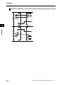
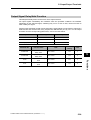
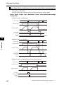
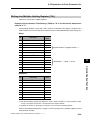
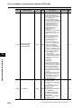
2-2 Wiring
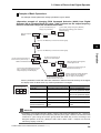
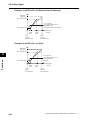
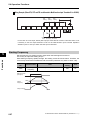
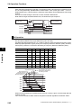
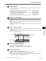
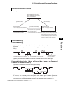
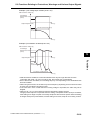
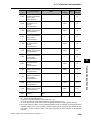
Wiring Example (Sink Logic)
Shorting bar
(sink logic)
RS−
RS+
S7/EB
MP
2
S6
S5/TH S4/GS2 S3/GS1
RP
FS
FV
FI
Design
Variable Resistor
Frequency reference
(1 to 2 kΩ)
S2
SC
S1
AM
SC
PC
PSC
P24
P2
P1/EDM
RY
RY
Signal during Frequency arrival
signal
RUN
Frequency reading
(27 VDC 50 mA max.)
When connecting a relay to the multi-function output terminal, install a surge-absorbing diode
in parallel with the relay. The output circuit can break down due to surge voltage when the relay
is switched on/off.
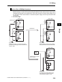
Switching Method for Input Control Logics
Multi-function input terminals are set to sink logic at the factory.
To switch the input control logic to source logic, remove the shorting bar between terminals
P24 and PSC on the control circuit terminal block, and connect it between terminals PSC and
SC.
(2) Source logic
(1) Sink logic
S2
S1
SC PSC P24
S2
S1
Shorting bar
SC PSC P24
Shorting bar
Communication
RS-485
Logic common and
power supply
Logic input
RS− S7
/EB
S6
S5 S4
S3 S2
/TH /GS2 /GS1
S1
SC PSC P24
Relay output
RS+ MP
RP
FS
FV
FI
SC
AM
PC
P1
P2
/EDM
Shorting
bar
MB MA MC
Communication Pulse Pulse Analog input and
output input
power supply
RS-485
2-19
Analog
output
Logic output
SYSDRIVE MX2 Series USER'S MANUAL (3G3MX2-A@@@@)
2-2 Wiring
Wire Sizes for Control Circuit Terminal Block and Relay Output Terminal Block
Control circuit terminal block
Relay output
terminal block
8 mm
Stripping length for
single/stranded wires:
Approx. 8 mm
Applicable wire
Single wire
(AWG)
mm2
Stranded wire mm2
(AWG)
Ferrules mm2 (AWG)
0.2 to 1.5
(AWG 24 to 16)
0.2 to 1.0
(AWG 24 to 17)
0.25 to 0.75
(AWG 24 to 18)
Relay output terminal
block
0.2 to 1.5
(AWG 24 to 16)
0.2 to 1.0
(AWG 24 to 17)
0.25 to 0.75
(AWG 24 to 18)
Recommended Terminal
To improve the ease of wiring and reliability of connection, use of ferrules of the following
specifications is recommended for signal wires:
Wire size
mm2 (AWG)
Ferrules
type*
L [mm]
φd [mm]
φD [mm]
0.25 (24)
AI 0.25-8YE
12.5
0.8
2.0
0.34 (22)
AI 0.34-8TQ
12.5
0.8
2.0
0.5 (20)
AI 0.5-8WH
14
1.1
2.5
0.75 (18)
AI 0.75-8GY
14
1.3
2.8
φd
8
L
φD
* Manufacturer: Phoenix Contact
Crimp tool CRIPMFOX UD 6-4 or CRIMPFOX ZA 3
SYSDRIVE MX2 Series USER'S MANUAL (3G3MX2-A@@@@)
2-20
Design
Control Circuit Terminal
Block
2
2-2 Wiring
Wiring Method
1. Use a slotted screwdriver (width: 2.5 mm or less) to push in the orange part of the
control circuit terminal block. (The wire insertion part opens.)
2. With the slotted screwdriver pushed in, insert the wire or ferrule in the wire insertion
part (round hole).
3. Pull out the slotted screwdriver, and the wire will be fixed.
2.5 mm
Design
2
Use a slotted screwdriver
to push in the
part.
Insert the wire.
Note: When pulling out a wire, do so by also pushing in the part denoted by
2-21
Pull out the slotted
screwdriver, and
the wire will be fixed.
with a slotted screwdriver.
SYSDRIVE MX2 Series USER'S MANUAL (3G3MX2-A@@@@)
2-2 Wiring
Connection to Programmable Controller (PLC)
Connection of Multi-function Input Terminal and Programmable Controller
When the Inverter's internal interface power
supply is used
S
P24
PSC
SC
S1
Sink logic
Shorting
bar
When an external power supply is used
(Remove shorting bar on the control terminal block.)
S
24 VDC
S7
Inverter
COM
Source logic
Output module
COM
P24
Shorting
bar
PSC
SC
Shorting P24
bar
PSC
SC
24 VDC
24VDC
Inverter
24 VDC P24
PSC
24 VDC
24 VDC
SC
S1
S1
S7
S7
S
Output module
2
Design
COM
Output module
24 VDC
S7
COM
No-voltage switch
P24
PSC
SC
S1
S
Inverter
Output module
Inverter
P24
P24
P24
Shorting PSC
bar
SC
24 VDC PSC
24 VDC PSC
SC
24 VDC
SC
S1
S1
S1
S1
S7
S7
S7
S7
Inverter
Inverter
Inverter
Inverter
SYSDRIVE MX2 Series USER'S MANUAL (3G3MX2-A@@@@)
24 VDC
2-22
2-2 Wiring
Connection of Multi-function Output Terminal and Programmable Controller
P1/EDM
Sink logic
P2
COM
PC 24 VDC
2
Inverter
Input module
Design
PC
Source logic
24 VDC
P1/EDM
P2
Inverter
2-23
COM
Input module
SYSDRIVE MX2 Series USER'S MANUAL (3G3MX2-A@@@@)
2-2 Wiring
Note on Use of Multiple Inverters
If multiple Inverters are using a common input (switch, etc.) and the Inverters are turned on at
different timings, a sneak current path will be generated as shown below and the input may be
recognized as ON when it is actually OFF. In this case, be sure to insert a diode (rating: 50 V/
0.1 A) in the location shown below or use external power supply circuits to prevent the sneak
current path.
1. For Sink Logic
Power ON
Power ON
Shorting line
P24
P24
PSC
PSC
SC
SC
Input ON
S1
2
Input OFF
S1
Shorting
line
Design
Add diodes.
Power OFF
Power OFF
P24
P24
PSC
PSC
SC
SC
S1
S1
Switch OFF
Without this diode, a sneak current path is
generated and the input turns ON when the
switch is OFF.
Switch OFF
Install a diode instead of the shorting
bar to prevent the sneak current path.
Power ON
P24
24-VDC
power
supply
Change to an external
power supply.
PSC
SC
Input OFF
S1
Power OFF
P24
PSC
SC
S1
Switch OFF
A sneak current path will not occur
if the short bar is removed and an
external power supply is used.
SYSDRIVE MX2 Series USER'S MANUAL (3G3MX2-A@@@@)
2-24
2-2 Wiring
2. For Source Logic
Power ON
Power ON
P24
P24
Shorting line PSC
PSC
SC
SC
Input ON
Input OFF
S1
S1
Add diodes.
Power OFF
2
Power OFF
P24
P24
PSC
PSC
SC
SC
S1
S1
Design
Shorting
line
Switch OFF
Without this diode, a sneak current path is
generated and the input turns ON when
the switch is OFF.
Switch OFF
Install a diode instead of the shorting
bar to prevent the sneak current path.
Power ON
P24
24-VDC
power
supply
PSC
SC
Input OFF
Change to an external
power supply.
S1
Power OFF
P24
PSC
SC
S1
Switch OFF
A sneak current path will not occur if
the short bar is removed and an
external power supply is used.
2-25
SYSDRIVE MX2 Series USER'S MANUAL (3G3MX2-A@@@@)
Operation
Describes the operating procedures including procedures for trial operation.
3-1
Name of Parts of the Digital Operator................................. 3-1
Names of Parts and their Descriptions ........................................... 3-1
Key Operation System .................................................................... 3-3
3-2
Operation Method ................................................................. 3-7
RUN Command/Frequency Reference Input .................................. 3-7
3-3
Test Run............................................................................... 3-10
3-4
Tripping................................................................................ 3-12
Procedure for Test Run................................................................. 3-10
Overview of Operation upon Tripping ........................................... 3-12
SYSDRIVE MX2 Series USER'S MANUAL (3G3MX2-A@@@@)
3
3-1 Name of Parts of the Digital Operator
3-1 Name of Parts of the Digital Operator
Names of Parts and their Descriptions
USB connector
8.8.8.8.
Data display
RUN Command enabled
LED indicator
Operation key
RJ45 connector
3
Operation
Name
POWER LED
Lit (green) while the Inverter is receiving power.
ALARM LED
Lit (red) when the Inverter trips.
For information on how to reset the trip, refer to "Method for
Resetting Trip" on page 7-1.
PROGRAM LED
indicator
Lit (green) when the displayed data (set value) can be
changed.
Blinks if the set value is invalid. Refer to "Warning Display"
on page 7-7.
RUN (during
RUN) LED
indicator
Lit (green) when the Inverter is running. (Lit when there is
either a "valid RUN command" or "inverter output."
Accordingly, it is also lit when a RUN command is issued at
a set frequency of 0 Hz or while the motor is decelerating
after the RUN command is turned OFF.)
Monitor LED
indicator (Hz)
Lit (green) when the displayed data is frequency.
Monitor LED
indicator (A)
Lit (green) when the displayed data is current.
RUN Command
enabled LED
indicator
Lit (green) when the RUN command is set to the Digital
Operator.
(The RUN key on the Digital Operator is enabled.)
Display
Various parameters, frequency/set value and other data are
displayed (red).
RUN key
Runs the Inverter. Take note that this key is enabled only
when the RUN command destination is the Digital Operator.
STOP/RESET
key
This key decelerates the Inverter to a stop. (Although the
STOP/RESET key is enabled even when a RUN command is
issued to a destination other than the Digital Operator (factory
default), it can be disabled by a Setting (b087).)
If the Inverter is already tripped, the trip will be reset (return
from the tripping).
8.8.8.8.
3-1
Description
SYSDRIVE MX2 Series USER'S MANUAL (3G3MX2-A@@@@)
3-1 Name of Parts of the Digital Operator
Name
Description
Mode key
Parameter is displayed: Move to the beginning of the next
function group.
Data is displayed: Cancel the setting and return to the
parameter display.
Individual input mode: Move the blinking digit to the left.
Regardless of the displayed screen, pressing and holding
this key (for 1 second or more) displays the data for Output
Frequency Monitor (d001).
Increment key
Decrement key
These keys are used to increment/decrement a parameter
or set data. Pressing and holding each key increases the
incrementing/decrementing speed.
Pressing the Increment and Decrement keys together
activates the "Individual Input MODE" where each digit can
be edited independently.
Enter key
Parameter is displayed: Move to the data display.
Data is displayed: Confirm/store the setting (in the
EEPROM) and return to the parameter
display.
Individual input mode: Move the blinking digit to the right.
Use this connector (mini-B type) to connect a PC.
The Inverter can still be operated from the Digital Operator
even when it is being operated using a PC, etc., via USB
communication.
RJ45 connector
Use this connector (RS-422) to connect the optional
Remote Operator. Once the Remote Operator is connected,
the keys on the main unit become disabled. In this case, use
b150 to set the item to be displayed.
SYSDRIVE MX2 Series USER'S MANUAL (3G3MX2-A@@@@)
3-2
Operation
USB connector
3
3-1 Name of Parts of the Digital Operator
Key Operation System
The following describes the key operation system of the Digital Operator.
When parameter is displayed
Function group "d"
: Move to data display
Parameter display
Data display
dk0k0k1
dk0k0k2
dk1k0k4
3
0.0k0
* Because the function group "d" is
a monitor mode, data cannot be changed.
d001: Output Frequency Monitor
When parameter is displayed
: Increases/decreases parameters by Increment/Decrement
keys. Pressing the Increment key at the end returns to the
beginning of the same function group.
When parameter is displayed
: Move to the next function group
Function group "F"
Store
Operation
Parameter display
Data display
fk0k0k1
5k0.0k0
fk0k0k2
5k0.0k1
fk0k0k4
F001: Output Frequency Setting
When data is displayed (F001 to F*03)
Since changed are reflected the moment they are changed, the display
does not blink when any of these parameters is changed.
: Store the value in the EEPROM and return to the parameter display
Function group "A"
: Return to the parameter display without storing the value in the EEPROM
Parameter display
ak0k0k1
0k0
ak0k0k2
0k1
ak1k6k5
Function group "b"
Function group "C"
: Confirm and store the changes and return to the parameter display
: Cancel the change and return to the parameter display
ck0k0k1
hk0k0k1
Function group "P"
pk0k0k1
Function group "U"
uk0k0k1
Function group "d"
dk0k0k1
A001: Frequency Reference Selection
When data is displayed
If data is changed, all digits will blink.
The new data is not yet reflected while its digits are still blinking.
bk0k0k1
Function group "H"
3-3
Data display
Pressing the Increment/Decrement keys
simultaneously in the parameter display
or data display can change the values
quickly and with ease.
For details, refer to the next page.
* Return to the function group "d" after the function group "U."
Return to d001
SYSDRIVE MX2 Series USER'S MANUAL (3G3MX2-A@@@@)
3-1 Name of Parts of the Digital Operator
Example of Basic Operations
An example of basic parameter change operations is given below.
<Operation example of changing RUN Command Selection (A002) from Digital
Operator (02) to Terminal Block (01) when "0.00" is shown on the output frequency
monitor screen after the power has been turned ON>
(2) Press the Mode Key to
display the parameters.
Output Frequency
Monitor
(1) The d001 (Output Frequency Monitor)
data is displayed during power ON time.
(Default setting)
0.0k0
dk0k0k1
(3) Press the Mode Key to move the function group.
fk0k0k1
3
(4) Press the Mode Key to move the function group.
(5) Press the Increment key to
increment the parameter by 1.
RUN Command Selection
Operation
ak0k0k1
(6) Press the Enter key to
move to the data display.
0k2
ak0k0k2
When the display first appears,
all data digits are lit.
(7) Press the Decrement key to
decrement the data by 1.
(9) Pressing and holding the Enter key
(for 1 second or more) jumps to the
output frequency monitor display.
0k1
(8) Press the Enter key to
confirm and store the value.
If data is changed, all digits will blink.
The new data is not yet reflected
while its digits are still blinking.
Since F parameters other than F004 are reflected in real time the moment they are changed,
the display does not blink when any of these parameters is changed.
Key name
Key arrangement
Function code is displayed
Data is displayed
Mode key
Move to the next function group Value is cancelled and
return to the parameter display
Enter key
Proceed to the data display
Increment key
Parameter is incremented by 1 Data is incremented by 1
Decrement key
Parameter is decremented by 1 Data is decremented by 1
Increment/Decrement are
pressed simultaneously
Move to the individual input
mode
Value is confirmed/stored and
return to the parameter display
Move to the individual input
mode
Reference
Regardless of the Digital Operator display, pressing and holding the Mode key (for 1 second or
more) displays the data for Output Frequency Monitor (d001) again. However, the selected mode
continues to cycle among the function groups while the Mode Key is held, according to the
designed operation of the key. (Example: A001→F001→b001→C001→...Elapse of 3 seconds,
followed by display of "50.00")
SYSDRIVE MX2 Series USER'S MANUAL (3G3MX2-A@@@@)
3-4
3-1 Name of Parts of the Digital Operator
Operation Example in the Individual Input Mode
If the parameter or data to be changed is far away from the currently displayed value, use the
individual input mode to change the parameter efficiently.
Step1: Increment/Decrement
keys are pressed
simultaneously.
Step2: Move the blinking digit to the
left/right using the Mode Key and
Enter key, and change the value
using the Increment/Decrement
keys.
+1
Step3: Press the Enter key
while the least
significant bit is
blinking, to confirm the
setting.
bk0k8k3
bk0k8k1
dk0k0k1
The most significant
digit blinks.
3
Move to left −1
3.0
Move to right
The individual input mode is effective regardless of whether a parameter or data is currently displayed.
Parameter display
Operation
fk0k0k1
Pressed simultaneously
(A)
(A)
fk0k0k1
fk0k0k1
fk0k0k1
fk0k0k1
ak0k0k1
fk1k0k1
fk0k1k1
fk0k0k2
The symbol digit blinks,
so increase/decrease the
parameter using the
Increment or Decrement
key.
The 100's digit blinks, so
increase/decrease the
parameter using the
Increment or Decrement
key.
The 10's digit blinks, so
increase/decrease the
parameter using the
Increment or Decrement
key.
The 10's digit blinks, so
increase/decrease the
parameter using the
Increment or Decrement
key.
If the specified parameter does not exist, the data display is
not shown and the blinking digit returns to the one at the far left.
Data display
5k0.0k0
Pressed simultaneously
(B)
(B)
5k0.0k0
5k0.0k0
5k0.0k0
5k0.0k0
6k0.0k0
5k1.0k0
5k0.1k0
5k0.0k1
The 1's digit blinks, so
increase/decrease the
value using the Increment
or Decrement key.
The 0.1's digit blinks, so
increase/decrease the
value using the Increment
or Decrement key.
The 0.01's digit blinks, so
increase/decrease the
value using the Increment
or Decrement key.
The 10's digit blinks, so
increase/decrease the
parameter using the
Increment or Decrement key.
Note 1: Pressing the Mode Key while the cursor (blinking digit) is at the far left moves the cursor to the
far right.
Note 2: Pressing the Increment and Decrement keys together in the individual input mode restores the
normal input mode.
Note 3: While the displayed data is blinking, the change has not yet reflected even when the function
group is "F."
3-5
SYSDRIVE MX2 Series USER'S MANUAL (3G3MX2-A@@@@)
3-1 Name of Parts of the Digital Operator
Operation Example When the Digital Operator is Connected to the Conventional Model
Although operations can be performed by connecting the conventional Digital Operator model
(3G3AX-OP01) to the 3G3MX2, the operations associated with the Mode key and Enter key
vary from that of the conventional key operation system. To switch to the parameter display to
data display, use the Enter key instead of the Mode key. Take note that pressing the FUNC
key while a parameter is displayed means moving the function group.
Key Operation System When the Conventional Digital Operator Model (3G3AX-OP01)
is Connected to the 3G3MX2
Move to data display
Return without saving
the changes
ak0k0k1
Conventional model 3G3AX-OP01
ak0k0k1
0k2
3
Move the function
group
bk0k0k1
Operation
0k1
3G3MX2
Return after saving the changes
(Reference) Key Operation System of the 3G3MX2 Digital Operator
Move to data display
Return without saving the changes
ak0k0k1
0k2
3G3MX2 Digital Operator
ak0k0k1
Move the function
group
bk0k0k1
0k1
Return after saving the changes
(Reference) Key Operation System When the Conventional Digital Operator Model (3G3AXOP01) is Connected to the Conventional Model
ak-k-k-
ak0k0k1
Move to data display
Return without saving
the changes
0k2
Conventional model 3G3AX-OP01
ak0k0k1
No applicable
function
bk0k0k1
0k1
Return after saving the changes
SYSDRIVE MX2 Series USER'S MANUAL (3G3MX2-A@@@@)
Conventional model
3G3MX, etc.
3-6
3-2 Operation Method
3-2 Operation Method
To operate the Inverter, two commands are required including a RUN command and frequency
reference. Take note that the Inverter does not operate if only one of these commands is
issued, such as when a RUN command is issued but not a frequency reference (0 Hz setting),
or a frequency reference is issued but not a RUN command.
RUN Command/Frequency Reference Input
Command/Reference Input From the Digital Operator
Operates the Inverter via the key operation of the standard Digital Operator or optional Remote
Operator.
Setting
3
Operation
Parameter
No.
Function name
Default
value
Data
Frequency
Reference
Selection 1
02 (Digital Operator)
A001
A002
RUN Command
Selection 1
02 (Digital Operator)
F001
Output
Frequency
Setting
0.0 to Max.
frequency
F004
RUN Direction
Selection
00 (Forward)
01 (Reverse)
Note
02
02
The RUN command enabled LED
indicator is lit.
6.00
00
Parameters cannot be changed
while the Inverter is operating.
Change the following parameters, if necessary:
Parameter
No.
Function name
Data
Default
value
F002
Acceleration
Time Setting 1
0.01 to 99.99 s 100.0 to 999.9 s
1,000. to 3,600. s
10.00 s
(30.00 s)
F003
Deceleration
Time Setting 1
0.01 to 3,600 s 100.0 to 999.9
1,000. to 3,600. s
10.00 s
(30.00 s)
Lit when the frequency
Lit when the RUN key is
pressed to start operation. data is displayed.
The RUN key is enabled
and the RUN command
enabled LED indicator is
lit when A002 is set to 02.
5k0.0k0
Operation
Refer to "Test Run" on page 3-10.
3-7
SYSDRIVE MX2 Series USER'S MANUAL (3G3MX2-A@@@@)
3-2 Operation Method
Command/Reference Input From the Control Circuit Terminal Block
Operates the Inverter by connecting the external signals (frequency setting volume, switch,
etc.) to the control circuit terminal block.
<Setting the Forward/Reverse Direction Using the FW/RV Input Terminal and Setting
the Frequency Using the Frequency Volume>
Setting
Parameter
No.
Function name
Default
value
Data
A001
Frequency
Reference
Selection 1
01 (Control circuit
terminal block)
A002
RUN Command
Selection 1
01 (Control circuit
terminal block)
C001
Multi-function
Input 1 Selection
00 (FW: Forward)
C002
Multi-function
Input 2 Selection
01 (RV: Reverse)
Note
02
02
00(FW)
If other input terminal is used, the
parameter number becomes different.
01(RV)
If other input terminal is used, the
parameter number becomes different.
Operation
Change the following parameters, if necessary:
Parameter
No.
Function name
Data
Default
value
F002
Acceleration
Time Setting 1
0.01 to 99.99 s 100.0 to 999.9 s
1,000. to 3,600. s
10.00 s
(30.00 s)
F003
Deceleration
Time Setting 1
0.01 to 99.99 s 100.0 to 999.9 s
1,000. to 3,600. s
10.00 s
(30.00 s)
Wiring the Control Circuit Terminal Block
F/R
setting
STP
setting
STA
setting
10 VDC
24 VDC
FS
FV
Frequency setting
volume
FI
SC
S3/GS1
S2
S1
*1
SC
PSC
P24
*2
Reverse Forward
input
input
*1 Allocate 16: FV/FI (Analog input switch) to a multi-function input to use as the voltage setting. If terminal
FV/FI is not allocated, the frequency reference becomes the sum of voltage input (FV) and current input
(FI). To use only one of voltage or current, therefore, short the other analog input to the SC terminal.
*2 This wiring diagram shows an example of using the built-in power supply of the Inverter. If an external
power supply is used, refer to "Connection to Programmable Controller (PLC)" on page 2-22.
Operation
Refer to "Test Run" on page 3-10.
SYSDRIVE MX2 Series USER'S MANUAL (3G3MX2-A@@@@)
3
3-8
3-2 Operation Method
<Running/Stopping the Inverter via 3-wire Input and Setting the Frequency Using an
Analog Current Signal>
Setting
3
Parameter
No.
Function name
Default
value
A001
Frequency Reference
Selection 1
01 (Control circuit
terminal block)
02
A002
RUN Command
Selection 1
01 (Control circuit
terminal block)
02
C001
Multi-function
Input 1 Selection
20 (STA: 3-wire
start)*
00 (FW)
If other input terminal is used, the
parameter number becomes different.
C002
Multi-function
Input 2 Selection
21 (STP: 3-wire stop)*
01 (RW)
If other input terminal is used, the
parameter number becomes different.
C003
Multi-function
Input 3 Selection
22 (F/R: 3-wire
forward/reverse)*
18 (RS)
If other input terminal is used, the
parameter number becomes different.
Data
Note
* For details on the 3-wire input method, refer to "3-wire Input Function (STA, STP, F/R)" on page 5-56.
Operation
Change the following parameters, if necessary:
Parameter
No.
Function name
Data
Default
value
F002
Acceleration
Time Setting 1
0.01 to 99.99 s 100.0 to 999.9 s
1,000. to 3,600. s
10.00 s
(30.00 s)
F003
Deceleration
Time Setting 1
0.01 to 99.99 s 100.0 to 999.9 s
1,000. to 3,600. s
10.00 s
(30.00 s)
Wiring the Control Circuit Terminal Block
F/R
setting
STP
setting
STA
setting
24 VDC
10 VDC
FS
FV
FI
SC
S3/GS1
S2
S1
SC
PSC
P24
*1
*2
Frequency setting
(4 to 20 mA)
Forward/
Stop
Operate
reverse (NC contact) (NO contact)
*1 Allocate 16: FV/FI (Analog input switch) to a multi-function input to use as the current setting. If terminal
FV/FI is not allocated, the frequency reference becomes the sum of voltage input (FV) and current input
(FI). To use only one of voltage and current, therefore, short the other analog input to the SC terminal.
*2 This wiring diagram shows an example of using the built-in power supply of the Inverter. If an external
power supply is used, refer to "Connection to Programmable Controller (PLC)" on page 2-22.
Operation
Refer to "Test Run" on page 3-10.
3-9
SYSDRIVE MX2 Series USER'S MANUAL (3G3MX2-A@@@@)
3-3 Test Run
3-3 Test Run
An example of basic connection is given below. Refer to "Operation Method" on page 3-7 when
issuing a RUN command/frequency reference from the control circuit terminal block.
Refer to "Name of Parts of the Digital Operator" on page 3-1 for the parameter setting method.
ELB
3-phase power
supply
R/L1(L1)*
S/L2
T/L3(N)*
U/T1
V/T2
W/T3
M
Motor
Inverter
G
3
* Connect to terminals L1 and N on a single-phase, 200-V Inverter (3G3MX2-AB@@@).
Operation
Procedure for Test Run
Command/Reference Input From the Digital Operator
1.
2.
3.
4.
5.
Check if the wires are connected correctly.
Turn on the power of the Inverter.
Set Frequency Reference Selection (A001) to "02" (Digital Operator).
Set RUN Command Selection (A002) to "02" (Digital Operator).
Set Output Frequency Setting (F001). It is recommended to set a low speed of approx.
10 Hz first to ensure safety.
6. Set RUN Direction Selection (F004).
7. Display Output Frequency Monitor (d001) and press the Enter key.
Confirm that "0.00" (Hz) is displayed.
8. Press the RUN key. The RUN (during RUN) LED indicator is lit and the motor starts
to turn.
9. Confirm the output frequency and motor rotation direction displayed on the Digital
Operator, and check if the Invertor is free from errors. For the motor rotation
direction, refer to Rotation Direction Monitor (d003).
10. If no problem is found, gradually increase the output frequency using Output
Frequency Setting (F001).
11. After checking the operation, press the STOP/RESET key. The motor starts to
decelerate and once it stops, the RUN (during RUN) LED indicator turns OFF.
Command/Reference Input From the Control Circuit Terminal Block
1.
2.
3.
4.
Check if the wires are connected correctly.
Turn on the power to the Inverter.
Set Frequency Reference Selection (A001) to "01" (Control circuit terminal block).
Set RUN Command Selection (A002) to "01" (Control circuit terminal block).
SYSDRIVE MX2 Series USER'S MANUAL (3G3MX2-A@@@@)
3-10
3-3 Test Run
5. Display Output Frequency Monitor (d001) and press the Enter key.
Confirm that "0.00" (Hz) is displayed.
6. After confirming that the analog voltage/current value for frequency reference is 0,
turn the RUN command ON. The RUN (during RUN) LED indicator is lit.
7. Gradually increase the analog voltage/current value for frequency reference.
* The frequency reference can be set first, before setting the RUN command in 6.
The motor accelerates/decelerates according to the acceleration/deceleration time
set in F002/F003.
8. The motor starts to turn. Confirm the output frequency and motor rotation direction
displayed on the Digital Operator, and check if the Inverter is free from errors.
9. After checking the operation, turn the RUN command OFF (turn the STP input ON
in the case of 3-wire input). The motor starts to decelerate and once it stops, the
RUN (during RUN) LED indicator turns OFF.
Check for tripping during acceleration/deceleration, and also check if the rotation speed and
frequency readings are correct.
If an overcurrent or overvoltage tripping occurs during trial operation, try to increase the
acceleration/deceleration time.
3
Operation
Confirm by Output Current Monitor (d002) and DC Voltage Monitor (d102) to confirm that the
current/voltage values are sufficiently away from the tripping values.
3-11
SYSDRIVE MX2 Series USER'S MANUAL (3G3MX2-A@@@@)
3-4 Tripping
3-4 Tripping
Upon detecting an error (overcurrent, overload, etc.) during operation, the Inverter cuts off the
output to the motor to protect the motor and Inverter. At the same time, the ALARM LED
indicator is lit and an error code is displayed. "Tripping" refers to this series of operations.
When a tripping occurs, the motor goes into free-run status. Identify the cause of the error from
the displayed error code, and remove the cause.
A RUN command is not accepted during a tripping. To reset a tripping, press the STOP/RESET
key. If a Reset (18: RS) is allocated to the multi-function input terminal, switching the reset
input from ON to OFF resets a tripping.
Note, however, that a tripping may not be reset depending on the cause of the tripping. In such
case, reconnect the power.
Also, confirm the RUN command and various other input signals thoroughly before executing
a reset. If the RUN command signal remains ON, the Inverter will restart immediately after the
reset.
3
Operation
Overview of Operation upon Tripping
Error detection
Normal operation → Error occurred
M
Display example
Alarm
E05.4
ALM
Output shut off
Free run
For details on error codes,
refer to "Error Code List"
in page 7-2.
Reset
M
* Perform a reset after identifying and removing the cause of the error
and checking the various signals such as RUN Command.
or
RS terminal input
ON → OFF
SYSDRIVE MX2 Series USER'S MANUAL (3G3MX2-A@@@@)
M
3-12
3-4 Tripping
Alarm occurred
RUN command FW, RV
Free run
Motor rotation speed
RS (reset) input
AL (alarm) output
(alarm signal)
Operation
3
3-13
SYSDRIVE MX2 Series USER'S MANUAL (3G3MX2-A@@@@)
Parameter List
3
Describes the parameters used by this Unit.
4-1
4-2
Monitor Mode ........................................................................ 4-1
Function Mode ...................................................................... 4-4
4
SYSDRIVE MX2 Series USER'S MANUAL (3G3MX2-A@@@@)
4-1 Monitor Mode
4-1 Monitor Mode
The description in "d001" is always displayed in the default setting at power-on. To fix the
optional display, change the setting in "b038".
The displayed parameters are limited in the default setting. To display all parameters, set Display
Selection (b037) to "00 (Complete display)".
Setting Soft Lock Selection (b031) to "10" permits data change during RUN.
Data ranges given in parentheses are for high-frequency mode. Refer to page 5-178 for details.
Parameter
Function name
No.
Parameter List
4
4-1
d001
Output
Frequency
Monitor
d002
d003
Monitor or data range
Data can
Data can
be
Default be set
changed Unit
setting during
during
RUN
RUN
Page
0.00 to 99.99
100.0 to 1,000. (High-frequency
mode)
−
yes
yes
Hz
5-1
Output Current
Monitor
0.0 to 655.3
−
−
−
A
5-1
Rotation
Direction
Monitor
F: Forward
o: Stop
r: Reverse
−
−
−
−
5-2
d004
PID Feedback
Value Monitor
0.00 to 99.99
100.0 to 999.9
1000. to 9999.
1000 to 9999(10000 to 99990)
100 to 999(100000 to 999000)
−
−
−
−
5-2
d005
Multi-function
Input Monitor
−
−
−
−
5-3
d006
Multi-function
Output Monitor
−
−
−
−
5-3
d007
Output
Frequency
Monitor (after
conversion)
0.00 to 99.99
100.0 to 999.9
1000. to 4000 (9999)
1000 to 4000 (9999/100)
−
yes
yes
−
5-4
d008
Real Frequency
Monitor
(−100/−999.) −400. to −100.
−99.9 to −10.0
−9.99 to −0.00
0.00 to 99.99
100.0 to 400.0 (400.1 to 999.9/1000.)
−
−
−
Hz
5-5
d009
Torque
Reference
Monitor
−200. to +200.
−
−
−
%
5-5
d010
Torque Bias
Monitor
−200. to +200.
−
−
−
%
5-6
d012
Output Torque
Monitor
−200. to +200.
−
−
−
%
5-6
d013
Output Voltage
Monitor
0.0 to 600.0
−
−
−
V
5-6
ON (Example)
OFF Terminal S1, S2: ON
Terminal S3 to S7: OFF
S7 S6 S5 S4 S3 S2 S1
ON (Example)
OFF Terminal P1, P2: ON
Terminal AL: OFF
MA P2 P1
SYSDRIVE MX2 Series USER'S MANUAL (3G3MX2-A@@@@)
4-1 Monitor Mode
Parameter
Function name
No.
Monitor or data range
Data can
Data can
be
Default be set
changed Unit
setting during
during
RUN
RUN
Page
d014
Input Power
Monitor
0.0 to 100.0
−
−
−
kW
5-7
d015
Integrated
Power Monitor
0.0 to 999.9
1000. to 9999.
1000 to 9999 (10000 to 99990)
100 to 999 (100000 to 999000)
−
−
−
−
5-7
d016
Total RUN
Time
0.0 to 9999.
1000 to 9999 (10000 to 99990)
100 to 999 (100000 to 999000)
−
−
−
h
5-8
d017
Power ON Time
0.0 to 9999.
1000 to 9999 (10000 to 99990)
100 to 999 (100000 to 999000)
−
−
−
h
5-8
d018
Fin
Temperature
Monitor
−20.0 to 150.0
−
−
−
°C
5-8
d022
Life
Assessment
Monitor
−
−
−
−
5-9
2 1
1: Capacitor on main
circuit board
2: Cooling fan
d024
(Reserved)
−
−
−
−
−
−
d029
Position
Command
Monitor
−268435455 to 268435455
(Displays MSB 4 digits including "−")
−
−
−
−
5-9
d030
Current
Position
Monitor
−268435455 to 268435455
(Displays MSB 4 digits including "−")
−
−
−
−
5-9
d050
User Selection
Monitor (2
types)
Monitor data selected by b160/b161 is
displayed.
−
−
−
−
5-10
d060
Inverter Mode
Monitor
The currently set mode is displayed.
I-C (IM motor heavy load)
I-V (IM motor light load)
H-I (IM motor high frequency)
−
−
−
−
5-10
d080
Fault Counter
0. to 9999.
1000 to 6553 (10000 to 65530)
−
−
−
Time
5-11
d081
Fault Monitor 1
(Latest)
d082
Fault Monitor 2
d083
Fault Monitor 3
−
−
−
−
5-11
d084
Fault Monitor 4
d085
Fault Monitor 5
Cause
→Frequency (Hz)
→Current (A)
→Voltage between PNs (V)
→RUN time (h)
→Power ON time (h)
d086
Fault Monitor 6
d025
d026
d027
SYSDRIVE MX2 Series USER'S MANUAL (3G3MX2-A@@@@)
4-2
Parameter List
d023
4
4-1 Monitor Mode
Parameter
Function name
No.
Monitor or data range
Data can
Data can
be
Default be set
changed Unit
setting during
during
RUN
RUN
Page
d090
Warning
Monitor
Warning code
−
−
−
−
5-11
d102
DC Voltage
Monitor
0.0 to 999.9
1000.
−
−
−
V
5-12
d103
Regenerative
Braking Load
Rate Monitor
0.0 to 100.0
−
−
−
%
5-12
d104
Electronic
Thermal Load
Rate Monitor
0.0 to 100.0
−
−
−
%
5-12
Parameter List
4
4-3
SYSDRIVE MX2 Series USER'S MANUAL (3G3MX2-A@@@@)
4-2 Function Mode
4-2 Function Mode
Parameter
Function name
No.
Monitor or data range
F001
Output
Frequency
Setting
0.0
Starting frequency to maximum
frequency 1/2
0.0 to 100.0 (PID function enabled)
F002
Acceleration
Time Setting 1
F202
F003
Data can
Data can
be
Default be set
changed Unit
setting during
during
RUN
RUN
6.00
yes
yes
Hz
%
0.01 to 99.99
100.0 to 999.9
1000. to 3600.
10.00
(30.00)
yes
yes
s
Acceleration
Time Setting 2
0.01 to 99.99
100.0 to 999.9
1000. to 3600.
10.00
(30.00)
yes
yes
s
Deceleration
Time Setting 1
0.01 to 99.99
100.0 to 999.9
1000. to 3600.
10.00
(30.00)
yes
yes
s
F203
Deceleration
Time Setting 2
0.01 to 99.99
100.0 to 999.9
1000. to 3600.
10.00
(30.00)
yes
yes
s
F004
RUN Direction
Selection
00: Forward
01: Reverse
00
no
no
−
5-15
5-24
4
5-23
4-4
Parameter List
SYSDRIVE MX2 Series USER'S MANUAL (3G3MX2-A@@@@)
Page
4-2 Function Mode
Basic setting
Parameter No. Function name
Analog input, others
Parameter List
4
A001
Frequency
Reference
Selection 1
A201
Frequency
Reference
Selection 2
A002
RUN Command
Selection 1
A202
RUN Command
Selection 2
A003
Base
Frequency 1
A203
Monitor or data range
00: Digital Operator (volume)
01: Control circuit terminal
block
02: Digital Operator (F001)
03: Modbus communication
(Modbus-RTU)
04: Optional board
06: Pulse train frequency
07: Do not set.
10: Operation function output
Data can
Data can be
Default
be set
Set data
changed Unit Page
setting
during
during RUN
RUN
02
no
no
−
5-15
−
5-22
02
no
no
02
no
no
02
no
no
30.0. to Maximum Frequency
1 [A004]
60.0
(1000.0)
no
no
Hz
Base
Frequency 2
30.0 to Maximum Frequency
2 [A204]
60.0
(1000.0)
no
no
Hz
A004
Maximum
Frequency 1
Base Frequency 1 [A003] to
400.0 (1000.)
60.0
(1000.0)
no
no
Hz
A204
Maximum
Frequency 2
Base Frequency 2 [A203] to
400.0 (1000.)
60.0
(1000.0)
no
no
Hz
A005
FV/FI Selection
00: Switch between FV
(voltage)/FI (current)
02: Switch between FV
(voltage)/volume*1
03: Switch between FI
(current)/volume*1
00
no
no
−
A011
FV Start
Frequency
0.00 to 99.99
100.0 to 400.0 (1000.)
0.00
no
yes
Hz
A012
FV End
Frequency
0.00 to 99.99
100.0 to 400.0 (1000.)
0.00
no
yes
Hz
A013
FV Start Ratio
0. to FV end ratio
0.
no
yes
%
A014
FV End Ratio
FV start ratio to 100.
100.
no
yes
%
A015
FV Start
Selection
00: Start Frequency A011
01: 0 Hz
01
no
yes
−
A016
Analog Input
Filter
(FV, FI
Sampling)
1. to 30.
31. (with 500 ms filter ±0.1 Hz
hysteresis)
8
no
yes
−
5-38
A017
(Reserved)
Do not change.
00
−
−
−
−
01: Control circuit terminal
block
02: Digital Operator
03: Modbus communication
(Modbus-RTU)
04: Optional board
5-26
5-28
5-38
5-40
*1. Enabled when the Digital Operator with Volume 3G3AX-OP01 is connected.
4-5
SYSDRIVE MX2 Series USER'S MANUAL (3G3MX2-A@@@@)
4-2 Function Mode
Monitor or data range
A019
Multi-step
Speed
Selection
00: Binary (16-step selection
with 4 terminals)
01: Bit (8-step selection with 7
terminals)
A020
Multi-step
Speed 1
Reference 0
A220
Multi-step
Speed 2
Reference 0
A021
Multi-step
Speed
Reference 1
0.00
A022
Multi-step
Speed
Reference 2
0.00
A023
Multi-step
Speed
Reference 3
0.00
A024
Multi-step
Speed
Reference 4
0.00
A025
Multi-step
Speed
Reference 5
0.00
A026
Multi-step
Speed
Reference 6
0.00
A027
Multi-step
Speed
Reference 7
A028
Multi-step
Speed
Reference 8
0.00
A029
Multi-step
Speed
Reference 9
0.00
A030
Multi-step
Speed
Reference 10
0.00
A031
Multi-step
Speed
Reference11
0.00
A032
Multi-step
Speed
Reference 12
0.00
A033
Multi-step
Speed
Reference 13
0.00
00
no
no
−
0.00
Starting frequency to
Maximum Frequency 1
6.00
yes
yes
Hz
0.00
Starting frequency to
Maximum Frequency 2
6.00
yes
yes
Hz
4
5-63
0.00
Starting frequency to
Maximum Frequency
SYSDRIVE MX2 Series USER'S MANUAL (3G3MX2-A@@@@)
0.00
yes
yes
Hz
4-6
Parameter List
Multi-step speed/jogging
Parameter No. Function name
Data can
Data can be
Default
be set
Set data
changed Unit Page
setting
during
during RUN
RUN
4-2 Function Mode
Multi-step speed/jogging
Parameter No. Function name
A034
Multi-step
Speed
Reference 14
A035
Multi-step
Speed
Reference 15
A038
Jogging
Frequency
Starting frequency to 9.99
A039
V/f characteristics
Parameter List
0.00
Starting frequency to
Maximum Frequency
0.00
yes
yes
Hz
0.00
yes
yes
Hz
Jogging Stop
Selection
00: Free run on jogging stop/
Disabled during operation
01: Deceleration stop on
jogging stop/Disabled
during operation
02: DC injection braking on
jogging stop/Disabled in
operation
03: Free run on jogging stop/
Enabled in operation
04: Deceleration stop on
jogging stop/Enabled in
operation
05: DC injection braking on
jogging stop/Enabled in
operation
04
no
yes
−
A041
Torque Boost
Selection 1
00: Manual torque boost
01: Automatic torque boost
00
no
no
−
A241
Torque Boost
Selection 2
00: Manual torque boost
01: Automatic torque boost
00
no
no
−
A042
Manual Torque 0.0 to 20.0 (Percentage of
Boost Voltage 1 motor voltage A082)
1.0
yes
yes
%
A242
Manual Torque 0.0 to 20.0 (Percentage of
Boost Voltage 2 motor voltage A282)
1.0
yes
yes
%
A043
Manual Torque
Boost
Frequency 1
0.0 to 50.0 (Ratio to base
frequency A003)
5.0
yes
yes
%
A243
Manual Torque
Boost
Frequency 2
0.0 to 50.0 (Ratio to base
frequency A203)
5.0
yes
yes
%
Control Method
1
00: Constant torque
characteristics (VC)
01: Reduced torque
characteristics (VP 1.7th
power <VC, if low speed>)
02: Free V/f setting
03: Sensorless vector control
(heavy load only)
00
no
no
−
4
A044
4-7
Monitor or data range
Data can
Data can be
Default
be set
Set data
changed Unit Page
setting
during
during RUN
RUN
5-63
0.00
5-59
5-49
5-46
5-144
SYSDRIVE MX2 Series USER'S MANUAL (3G3MX2-A@@@@)
4-2 Function Mode
V/f characteristics
Parameter No. Function name
Monitor or data range
Data can
Data can be
Default
be set
Set data
changed Unit Page
setting
during
during RUN
RUN
A244
Control Method
2
00: Constant torque
characteristics (VC)
01: Reduced torque
characteristics (VP 1.7th
power <VC, if low speed>)
02: Free V/f setting
03: Sensorless vector control
(heavy load only)
A045
Output Voltage
Gain 1
20. to 100.
A245
Output Voltage
Gain 2
20. to 100.
100.
yes
yes
%
A046
Automatic
Torque Boost
Voltage
Compensation
Gain 1
0. to 255.
100.
yes
yes
−
A246
Automatic
Torque Boost
Voltage
Compensation
Gain 2
0. to 255.
100.
yes
yes
−
A047
Automatic
Torque Boost
Slip
Compensation
Gain 1
0. to 255.
100.
yes
yes
−
A247
Automatic
Torque Boost
Slip
Compensation
Gain 2
0. to 255.
100.
yes
yes
−
00
no
no
-
100.
yes
yes
%
5-46
5-144
5-72
4
SYSDRIVE MX2 Series USER'S MANUAL (3G3MX2-A@@@@)
4-8
Parameter List
5-49
4-2 Function Mode
External DC injection braking
Parameter No. Function name
External DC injection braking
Parameter List
4
4-9
Monitor or data range
A051
Internal DC
Injection
Braking
Selection
00: Disabled
01: Enabled
02: Enabled
(Operates only on set
frequencies.)
A052
Internal DC
Injection
Braking
Frequency
A053
Data can
Data can be
Default
be set
Set data
changed Unit Page
setting
during
during RUN
RUN
00
yes
no
−
0.00 to 60.00
0.50
no
yes
Hz
DC Injection
Braking Delay
Time
0.0 to 5.0
0.0
no
yes
s
A054
DC Injection
Braking Power
0. to 100./70.
(heavy load/light load)
50
no
yes
%
A055
DC Injection
Braking Time
0.0 to 60.0
0.5
no
yes
s
A056
DC Injection
Braking Edge/
Level Selection
00: Edge operation
01: Level operation
01
no
yes
−
A057
Startup DC
Injection
Braking Power
0. to 100./70. (heavy load/light
load)
0.
no
yes
%
A058
Startup Internal
DC Injection
Braking Time
0.0 to 60.0
0.0
no
yes
s
A059
DC Injection
Braking Carrier
Frequency
2.0 to 15.0/10.0
(heavy load/light load or high
frequency )
5-135
5-135
5.0/2.0
no
yes
kHz
SYSDRIVE MX2 Series USER'S MANUAL (3G3MX2-A@@@@)
4-2 Function Mode
Monitor or data range
A061
Frequency
Upper Limit 1
0.00
Frequency Lower Limit 1 to
Maximum Frequency 1
0.00
no
yes
Hz
A261
Frequency
Upper Limit 2
0.00
Frequency Lower Limit 2 to
Maximum Frequency 2
0.00
no
yes
Hz
A062
Frequency
Lower Limit 1
0.00
Starting Frequency to
Frequency Upper Limit 1
0.00
no
yes
Hz
A262
Frequency
Lower Limit 2
0.00
Starting Frequency to
Frequency Upper Limit 2
0.00
no
yes
Hz
A063
Jump
Frequency 1
0.00 to 99.99
100.0 to 400.0 (1000.)
0.00
no
yes
Hz
A064
Jump
Frequency
Width 1
0.00 to 10.00(100.0)
0.50
no
yes
Hz
A065
Jump
Frequency 2
0.00 to 99.99
100.0 to 400.0 (1000.)
0.00
no
yes
Hz
A066
Jump
Frequency
Width 2
0.00 to 10.00 (100.0)
0.50
no
yes
Hz
A067
Jump
Frequency 3
0.00 to 99.99
100.0 to 400.0 (1000.)
0.00
no
yes
Hz
A068
Jump
Frequency
Width 3
0.00 to 10.00 (100.0)
0.50
no
yes
Hz
A069
Acceleration
0.00 to 99.99
Stop Frequency 100.0 to 400.0 (1000.)
0.00
no
yes
Hz
A070
Acceleration
Stop Time
0.0
5-60
4
5-61
0.0 to 60.0
SYSDRIVE MX2 Series USER'S MANUAL (3G3MX2-A@@@@)
Parameter List
Others
Limit/jump
Parameter No. Function name
Data can
Data can be
Default
be set
Set data
changed Unit Page
setting
during
during RUN
RUN
5-62
no
yes
s
4-10
4-2 Function Mode
PID control
Parameter No. Function name
Parameter List
4
A071
PID Selection
00: Disabled
01: Enabled
02: Reverse output enabled
A072
PID P Gain
A073
00
no
yes
−
0.00 to 25.00
1.00
yes
yes
−
PID I Gain
0.0 to 999.9
1000. to 3600.
1.0
yes
yes
s
A074
PID D Gain
0.00 to 99.99
100.0
0.00
yes
yes
s
A075
PID Scale
0.01 to 99.99
1.00
no
yes
Time
A076
PID Feedback
Selection
00: FI (current)
01: FV (voltage)
02: Modbus communication
(Modbus-RTU)
03: Pulse train frequency
10: Operation function output
A077
no
yes
−
PID Deviation
00: Disabled
Reverse Output 01: Enabled
00
no
yes
−
A078
PID Variable
Range Limit
0.0 to 100.0
0.0
no
yes
%
A079
PID
Feedforward
Selection
00: Disabled
01: FV (voltage)
02: FI (current)
00
no
yes
−
02
no
no
02
no
no
200/
400
no
no
200/
400
no
no
V
0.300
no
yes
s
A281
AVR
5-73
00
A081
4-11
Monitor or data range
Data can
Data can be
Default
be set
Set data
changed Unit Page
setting
during
during RUN
RUN
AVR Selection 1 00: Always ON
01: Always OFF
AVR Selection 2 02: OFF during deceleration
A082
Motor Incoming
Voltage
Selection 1
A282
Motor Incoming
Voltage
Selection 2
A083
AVR Filter Time
Parameter
A084
AVR
Deceleration
Voltage Gain
200V class: 200/215/220/230/
240
400V class: 380/400/415/440/
460/480
0.000 to 10.00
−
5-27
V
5-26
5-148
5-27
50. to 200.
100.
no
yes
%
SYSDRIVE MX2 Series USER'S MANUAL (3G3MX2-A@@@@)
4-2 Function Mode
Operation mode/acceleration/deceleration
Parameter No. Function name
A085
RUN Mode
Selection
Monitor or data range
00: Normal operation
01: Energy-saving operation
Data can
Data can be
Default
be set
Set data
changed Unit Page
setting
during
during RUN
RUN
00
no
no
−
5-79
A086
Energy-saving
Response/
Accuracy
Adjustment
0.0 to 100.0
50.0
yes
yes
−
4
Parameter List
SYSDRIVE MX2 Series USER'S MANUAL (3G3MX2-A@@@@)
4-12
4-2 Function Mode
Operation mode/acceleration/deceleration function
Parameter No. Function name
Parameter List
4
Monitor or data range
Data can
Data can be
Default
be set
Set data
changed Unit Page
setting
during
during RUN
RUN
A092
1st
Acceleration
Time 2
10.00
(15.00)
yes
yes
A292
2nd
Acceleration
Time 2
10.00
(15.00)
yes
yes
A093
1st
Deceleration
Time 2
A293
2nd
Deceleration
Time 2
A094
2-step
Acceleration/
Deceleration
Selection 1
A294
2-step
Acceleration/
Deceleration
Selection 2
A095
0.01 to 99.99
100.0 to 999.9
1000. to 3600.
s
00: Switched via 2CH terminal
01: Switched by setting
02: Enabled only when
switching forward/reverse
10.00
(15.00)
yes
yes
10.00
(15.00)
yes
yes
00
no
no
−
00
no
no
2-step
Acceleration
Frequency 1
0.00
no
no
A295
2-step
Acceleration
Frequency 2
0.00
no
no
A096
2-step
Deceleration
Frequency 1
A296
A097
0.00 to 99.99
100.0 to 400.0 (1000.)
Hz
0.00
no
no
2-step
Deceleration
Frequency 2
0.00
no
no
Acceleration
Pattern
Selection
01
no
no
00: Linear
01: S shape
02: U shape
03: Reverse-U shape
04: EL-S shape
A098
4-13
Deceleration
Pattern
Selection
5-66
−
01
no
5-68
no
SYSDRIVE MX2 Series USER'S MANUAL (3G3MX2-A@@@@)
4-2 Function Mode
A101
FI Start
Frequency
A102
FI End
Frequency
A103
FI Start Ratio
A104
Monitor or data range
0.00
no
yes
0.00
no
yes
0. to FI end ratio
20.
no
yes
%
FI End Ratio
FI start ratio to 100.
100.
no
yes
%
A105
FI Start
Selection
00: Use Start Frequency
[A101]
01: 0 Hz
00
no
yes
−
A131
Acceleration
Curve
Parameter
02
no
yes
A132
Deceleration
Curve
Parameter
A141
Operation
Frequency
Selection 1
A142
Operation
Frequency
Selection 2
0.00 to 99.99
100.0 to 400.0 (1000.)
Hz
01 (small curve) to 10 (large
curve)
−
02
no
5-40
5-68
yes
4
00: Digital Operator
01: Digital Operator (volume) *1
02: FV (voltage) input
03: FI (current) input
04: Modbus communication
(Modbus-RTU)
05: Optional board
07: Pulse train frequency
02
yes
no
−
03
yes
5-70
no
*1. Enabled when the Digital Operator with Volume 3G3AX-OP01 is connected.
SYSDRIVE MX2 Series USER'S MANUAL (3G3MX2-A@@@@)
4-14
Parameter List
Operation frequency
Acceleration/Deceleration
Frequency adjustment
Parameter No. Function name
Data can
Data can be
Default
be set
Set data
changed Unit Page
setting
during
during RUN
RUN
4-2 Function Mode
Acceleration/Deceleration
Operation frequency
Parameter No. Function name
A143
Operation
Function
Operator
Selection
00: Addition (A141+A142)
01: Subtraction (A141−A142)
02: Multiplication (A141 ×
A142)
A145
Frequency
Addition
Amount Setting
0.00 to 99.99
100.0 to 400.0 (1000.)
A146
Frequency
Addition Sign
Selection
00: Frequency reference +
A145
01: Frequency reference −
A145
A150
Frequency adjustment
4-15
00
no
yes
−
0.00
no
yes
Hz
no
yes
EL-S Shape
Acceleration
Curve Ratio 1
10.
no
no
A151
EL-S Shape
Acceleration
Curve Ratio 2
10.
no
no
A152
EL-S Shape
Deceleration
Curve Ratio 1
A153
0. to 50.
−
%
10.
no
no
EL-S Shape
Deceleration
Curve Ratio 2
10.
no
no
A154
Deceleration
0.00 to 99.99
Stop Frequency 100.0 to 400.0 (1000.)
0.00
no
yes
Hz
A155
Deceleration
Stop Time
0.0
no
yes
s
A156
PID Sleep
0.00 to 99.99
Function
100.0 to 400.0 (1000.)
Operation Level
0.00
no
yes
Hz
A157
PID Sleep
Operation
Delay Time
0.0 to 25.5
0.0
no
yes
s
A161
VR Start
Frequency
0.00 to 99.99
100.0 to 400.0 (1000.)
0.00
no
yes
Hz
A162
VR End
Frequency
0.00 to 99.99
100.0 to 400.0 (1000.)
0.00
no
yes
Hz
A163
VR Start Ratio
0. to VR End Ratio
0.
no
yes
%
A164
VR End Ratio
VR Start Ratio to 100
100.
no
yes
%
A165
VR Start
Selection
00: Use Start Frequency
[A161]
01: 0 Hz
01
no
yes
Hz
0.0 to 60.0
5-70
5-71
00
PID
Others
Parameter List
4
Monitor or data range
Data can
Data can be
Default
be set
Set data
changed Unit Page
setting
during
during RUN
RUN
5-68
5-62
5-73
5-40
SYSDRIVE MX2 Series USER'S MANUAL (3G3MX2-A@@@@)
4-2 Function Mode
Momentary power interruption/Trip restart
Parameter No. Function name
Monitor or data range
Data can
Data can be
Default
be set
Set data
changed Unit Page
setting
during
during RUN
RUN
00: Trip
01: 0 Hz restart
02: Frequency matching
restart
03: Trip after frequency
matching deceleration
stop
04: Frequency pull-in restart
00
b002
Allowable
Momentary
Power
Interruption
Time
0.3 to 25.0
1.0
no
yes
s
b003
Restart
Standby Time
0.3 to 100.0
1.0
no
yes
s
b001
Retry Selection
no
yes
−
5-96
5-96
5-100
5-103
4
Parameter List
SYSDRIVE MX2 Series USER'S MANUAL (3G3MX2-A@@@@)
4-16
4-2 Function Mode
Momentary power interruption/Trip restart
Parameter No. Function name
Electronic Thermal
Parameter List
4
4-17
Monitor or data range
b004
Momentary Power
Interruption/
Undervoltage Trip
During Stop
Selection
b005
Restart During
Momentary
00: 16 times
Power
01: Unlimited
Interruption
Count Selection
b007
Frequency
Matching Lower
Limit
Frequency
Setting
0.00 to 99.99
100.0 to 400.0 (1000.)
b008
Overvoltage/
Overcurrent
Restart
Selection
00: Disabled
01: Enabled
02: Disabled during stop and
deceleration stop
Data can
Data can be
Default
be set
Set data
changed Unit Page
setting
during
during RUN
RUN
00
no
yes
−
5-96
00
no
yes
−
0.00
no
yes
Hz
00: Trip
01: 0 Hz restart
02: Frequency matching
restart
03: Trip after frequency
matching deceleration
stop
04: Frequency pull-in restart
00
no
yes
−
b010
Overvoltage/
Overcurrent
Restart Count
Selection
1 to 3
3
no
yes
Time
b011
Overvoltage/
Overcurrent
Restart
Standby Time
0.3 to 100.0
1.0
no
yes
s
b012
Electronic
Thermal Level 1
Inverter
rated
current
no
yes
Inverter
rated
current
no
yes
01
no
yes
b212
Electronic
Thermal Level 2
b013
Electronic
Thermal
Characteristics
Selection 1
b213
Electronic
Thermal
Characteristics
Selection 2
0.20 × Rated current to 1.00 ×
Rated current
5-97
5-100
5-103
5-97
A
5-110
00: Reduced torque
characteristics
01: Constant torque
characteristics
02: Free setting
−
01
no
yes
SYSDRIVE MX2 Series USER'S MANUAL (3G3MX2-A@@@@)
4-2 Function Mode
Electronic Thermal
Parameter No. Function name
Monitor or data range
b015
Free-electronic
Thermal
Frequency 1
b016
Free-electronic
0.00 to Rated current
Thermal Current 1
b017
Free-electronic
Thermal
Frequency 2
b018
Free-electronic
0.00 to Rated current
Thermal Current 2
b019
Free-electronic
Thermal
Frequency 3
b020
Free-electronic
Thermal
Current 3
b021
Overload Limit 1
Selection
b221
Overload Limit 2
Selection
b022
Overload Limit 1
Level
b222
Overload Limit 2
Level
b023
Overload Limit 1
Parameter
b223
Overload Limit 2
Parameter
0. to Free-electronic Thermal
Frequency 2
Free-electronic Thermal
Frequency 1 to Freeelectronic Thermal Current 3
Free-electronic Thermal
Frequency 2 to 400. (1000.)
Data can
Data can be
Default
be set
Set data
changed Unit Page
setting
during
during RUN
RUN
0.
no
yes
Hz
0.00
no
yes
A
5-112
0.
no
yes
Hz
0.00
no
yes
A
0.
no
yes
Hz
b024
b025
0.00 to Rated current
0.00
no
yes
01
no
yes
01
no
yes
no
yes
A
no
yes
A
1.0
no
yes
1.0
no
yes
Overload Limit 1
Selection 2
00: Disabled
01: Enabled in acceleration/
constant speed operation
02: Enabled in constant speed
operation
03: Enabled during
acceleration/constant
speed operation
(accelerated during
regeneration)
01
no
yes
−
Overload Limit 1
Level 2
0.20 × Rated current to 2.00 ×
rated current (heavy load
setting)
0.20 × Rated current to 1.50 ×
rated current (light load
setting)
Rated
current ×
1.50
(heavy)
or 1.20
(light)
no
yes
A
00: Disabled
01: Enabled in acceleration/
constant speed operation
02: Enabled in constant speed
operation
03: Enabled during
acceleration/constant
speed operation
(accelerated during
regeneration)
0.20 × Rated current to 2.00 ×
rated current (heavy load
setting)
0.20 × Rated current to 1.50 ×
rated current (light load
setting)
0.1 to 999.9
1000. to 3000.
SYSDRIVE MX2 Series USER'S MANUAL (3G3MX2-A@@@@)
A
4
−
Rated
current ×
1.50
(heavy)
or 1.20
(light)
s
Parameter List
Overload limit, Overcurrent Protection
5-112
5-114
4-18
4-2 Function Mode
Overload limit, Overcurrent Protection
Parameter No. Function name
b026
Overload Limit 1
Parameter 2
0.1 to 999.9
1000. to 3000.
1.0
no
yes
s
5-114
b027
Overcurrent
Suppression
Selection
00: Disabled
01: Enabled
00
no
yes
−
5-116
b028
0.20 × Rated current to 2.00 ×
rated current (heavy load
Frequency Pull- setting)
in Restart Level 0.20 × Rated current to 1.50 ×
rated current (light load
setting)
Inverter
rated
current
no
yes
A
b029
Frequency Pull0.1 to 999.9
in Restart
1000. to 3000.
Parameter
Others
Lock
Parameter List
5-97
5-100
5-103
0.50
no
yes
s
b030
Starting
Frequency at
00: Frequency at interruption
Frequency Pull- 01: Maximum frequency
in Restart
02: Set frequency
Selection
00
no
yes
−
b031
Soft Lock
Selection
00: Data other than b031
cannot be changed when
terminal SFT is ON.
01: Data other than b031 and
set frequency cannot be
changed when terminal
SFT is ON.
02: Data other than b031
cannot be changed.
03: Data other than b031 and
set frequency cannot be
changed.
10: Data can be changed
during RUN.
01
no
yes
−
5-84
b033
Motor Cable
Length Code
Selection
5. to 20.
10.
no
yes
−
5-145
b034
RUN Time/Power
ON Time Level
0. to 9999. (0 to 99990)
1000 to 6553 (100000 to
655350)
0.
no
yes
h
5-124
b035
Rotation
Direction Limit
Selection
00: No direction limit
01: Only Forward is enabled
(Reverse is limited)
02: Only Reverse is enabled
(Forward is limited)
00
no
no
−
5-23
4
4-19
Monitor or data range
Data can
Data can be
Default
be set
Set data
changed Unit Page
setting
during
during RUN
RUN
SYSDRIVE MX2 Series USER'S MANUAL (3G3MX2-A@@@@)
4-2 Function Mode
Parameter No. Function name
0 (Reduced voltage startup
time: short) to 255 (Reduced
voltage startup time: long)
2
no
yes
−
5-58
Display
Selection
00: Complete display
01: Individual display of
functions
02: User setting + b037
03: Data comparison display
04: Basic display
05: Monitor display only
04
no
yes
−
5-88
b038
Initial Screen
Selection
000: Screen on which the
Enter key was last
pressed
001 to 060: d001 to d060
201: F001
202: Do not use this setting.
001
no
yes
−
5-86
b039
User Parameter
Automatic
Setting
Function
00: Disabled
01: Enabled
00
no
yes
−
5-177
b040
Torque Limit
Selection
00: Four-quadrant separate
setting
01: Terminal switching
02: Analog voltage input
03: Optional board
00
no
yes
−
b041
Torque Limit 1
(Four-quadrant
Mode Forward
Power
Running)
200.
no
yes
b042
Torque Limit 2
(Four-quadrant
Mode Reverse
Regeneration)
200.
no
yes
b043
Torque Limit 3
(Four-quadrant
Mode Reverse
Power
Running)
b044
Torque Limit 4
(Four-quadrant
Mode Forward
Regeneration)
b045
Torque
LADSTOP
Selection
Torque limit
Others
b037
0. to 200.
no (Torque limit disabled)
5-153
%
200.
no
yes
200.
no
yes
00: Disabled
01: Enabled
00
no
yes
−
5-155
b046
Reverse
Rotation
Prevention
Selection
00: Disabled
01: Enabled
00
no
yes
−
5-157
b049
Heavy Load/
Light Load
Selection
00: Heavy load mode
01: Light load mode
00
no
no
−
5-13
SYSDRIVE MX2 Series USER'S MANUAL (3G3MX2-A@@@@)
4
Parameter List
Reduced
Voltage Startup
Selection
b036
Other
Monitor or data range
Data can
Data can be
Default
be set
Set data
changed Unit Page
setting
during
during RUN
RUN
4-20
4-2 Function Mode
Controlled deceleration on power loss
Parameter No. Function name
Window comparator
Window comparator
Parameter List
4
4-21
b050
Controlled
Deceleration on
Power Loss
Monitor or data range
00: Controlled deceleration on
power loss disabled.
01: Controlled deceleration on
power loss enabled
(deceleration stop)
02: Controlled deceleration on
power loss (constant
voltage, without recovery)
03: Controlled deceleration on
power loss (constant
voltage, with recovery)
Data can
Data can be
Default
be set
Set data
changed Unit Page
setting
during
during RUN
RUN
00
no
no
−
5-106
b051
DC Bus Voltage
Trigger Level of
Ctrl. Decel.
0.0 to 999.9
1000.
220.0/
440.0
no
no
V
b052
Deceleration
Hold Level of
Ctrl. Decel
0.0 to 999.9
1000.
360.0/
720.0
no
no
V
b053
Deceleration
Time of Ctrl.
Decel
0.01 to 3600.00
1.0
no
no
s
b054
Freq. Drop to
0.00 to 10.00 (100.0)
Start Ctrl. Decel
0.00
no
no
Hz
b060
Window
Comparator FV
Upper Limit
Level
Set an upper limit level.
Setting range: 0. to 100.
Lower limit: Lower limit level +
Hysteresis width × 2
100.
yes
yes
%
b061
Window
Comparator FV
Lower Limit
Level
Set a lower limit level. Setting
range: 0. to 100.
Upper limit: Upper limit level −
Hysteresis width × 2
0.
yes
yes
%
b062
Window
Comparator FV
Hysteresis
Width
Set a hysteresis width for the
upper and lower limit levels.
Setting range: 0. to 10.
Upper limit: (Upper limit level −
Lower limit level)/2
0.
yes
yes
%
b063
Window
Comparator FI
Upper Limit
Level
Set an upper limit level.Setting
range: 0. to 100.
Lower limit: Lower limit level +
Hysteresis width × 2
100.
yes
yes
%
b064
Window
Comparator FI
Lower Limit
Level
Set a lower limit level.
Setting range: 0. to 100.
Upper limit: Upper limit level −
Hysteresis width × 2
0.
yes
yes
%
b065
Window
Comparator FI
Hysteresis Width
Set a hysteresis width for the
upper and lower limit levels.
Setting range: 0. to 10.
Upper limit: (Upper limit level −
Lower limit level)/2
0.
yes
yes
%
Analog
Operation Level
b070
at FV
Disconnection
0. to 100.
no (ignore)
no
no
yes
−
Analog
Operation Level
b071
at FI
Disconnection
0. to 100.
no (ignore)
5-106
5-132
5-132
5-132
no
no
yes
−
SYSDRIVE MX2 Series USER'S MANUAL (3G3MX2-A@@@@)
4-2 Function Mode
Parameter No. Function name
b075
Ambient
Temperature
−10. to 50.
40.
yes
yes
°C
b078
Integrated
Power Clear
Cleared with the Enter key
after changing to 01
00
yes
yes
−
1. to 1000.
1.
yes
yes
−
0.10 to 9.99 (100.)
0.50
no
yes
Hz
5-57
2.0 to 15.0/10.0
(heavy load/light load or high
frequency)
* With derating
10.0/
2.0
(5.0)
no
yes
kHz
5-51
00: Initialization disabled
01: Fault monitor clear
02: Initializes data
03: Fault monitor clear + Data
initialization
04: Do not set.
00
no
no
−
Initialization
b085
Data Selection
00: Do not change.
00
no
no
−
Frequency
b086 Conversion
Coefficient
0.01 to 99.99
1.00
yes
yes
−
5-4
00: Enabled
01: Disabled
02: Only reset is enabled
00
no
yes
−
5-84
Free-run Stop
b088
Selection
00: 0 Hz restart
01: Frequency matching
restart
02: Frequency pull-in restart
00
no
yes
−
5-103
Automatic
b089 Carrier
Reduction
00: Disabled
01: Enabled/depends on
current
02: Enabled/depends on fin
temperature
01
no
no
−
5-52
Usage Rate of
b090 Regenerative
Braking
0.0 to 100.0
0.0
no
yes
%
5-141
b091 Stop Selection
00: Deceleration stop
01: Free-run stop
00
no
yes
−
5-24
00: Always
01: Only during operation
(including 5 minutes after
power on/stop)
02: Depends on the fin
temperature
01
no
yes
−
00: Total operation time count
01: Clear total operation time
00
Integrated
b079 Power Display
Scale
b082
Starting
Frequency
Carrier
b083
Frequency
b084
b087
b092
Initialization
Selection
STOP Key
Selection
Cooling Fan
Operation
Cooling Fan
b093 Total Operation
Time Clear
5-127
5-7
SYSDRIVE MX2 Series USER'S MANUAL (3G3MX2-A@@@@)
5-174
4
5-127
no
no
−
4-22
Parameter List
Others
Monitor or data range
Data can
Data can be
Default
be set
Set data
changed Unit Page
setting
during
during RUN
RUN
4-2 Function Mode
Others
Parameter No. Function name
V/f free setting
Parameter List
4
4-23
Monitor or data range
Data can
Data can be
Default
be set
Set data
changed Unit Page
setting
during
during RUN
RUN
Initialization
b094 Target
Selection
00: All data
01: All data other than
terminals/communication
02: U*** registration function
only
03: Other than U***
registration function and
Display Selection (b037)
00
no
no
−
Regenerative
b095 Braking
Selection
00: Disabled
01: Enabled (Disabled while
stopped)
02: Enabled (Enabled while
operating and stopped)
00
no
yes
−
Regenerative
b096 Braking ON
Level
330 to 380
660 to 760
5-174
5-141
360/
720
no
yes
V
b100
Free V/f
Frequency 1
0. to Free V/f Frequency 2
0.
no
no
Hz
b101
Free V/f
Voltage 1
0.0 to 800.0
0.0
no
no
V
b102
Free V/f
Frequency 2
Free V/f Frequency 1 to Free
V/f Frequency 3
0.
no
no
Hz
b103
Free V/f
Voltage 2
0.0 to 800.0
0.0
no
no
V
b104
Free V/f
Frequency 3
Free V/f Frequency 2 to Free
V/f Frequency 4
0.
no
no
Hz
b105
Free V/f
Voltage 3
0.0 to 800.0
0.0
no
no
V
b106
Free V/f
Frequency 4
Free V/f Frequency 3 to Free
V/f Frequency 5
0.
no
no
Hz
b107
Free V/f
Voltage 4
0.0 to 800.0
0.0
no
no
V
b108
Free V/f
Frequency 5
Free V/f Frequency 4 to Free
V/f Frequency 6
0.
no
no
Hz
b109
Free V/f
Voltage 5
0.0 to 800.0
0.0
no
no
V
b110
Free V/f
Frequency 6
Free V/f Frequency 5 to Free
V/f Frequency 7
0.
no
no
Hz
b111
Free V/f
Voltage 6
0.0 to 800.0
0.0
no
no
V
b112
Free V/f
Frequency 7
Free V/f Frequency 6 to 400.
(1000.)
0.
no
no
Hz
b113
Free V/f
Voltage 7
0.0 to 800.0
0.0
no
no
V
5-47
5-47
SYSDRIVE MX2 Series USER'S MANUAL (3G3MX2-A@@@@)
4-2 Function Mode
Monitor or data range
b120
Brake Control
Function
Selection
00: Disabled
01: Enabled
00
no
yes
−
b121
Brake Release
Wait Time
0.00 to 5.00
0.00
no
yes
s
b122
Acceleration
Wait Time
0.00 to 5.00
0.00
no
yes
s
b123
Stop Wait Time
0.00 to 5.00
0.00
no
yes
s
b124
Brake Wait
Time for
Confirmation
0.00 to 5.00
0.00
no
yes
s
b125
Brake Release
Frequency
0.00 to 99.99
100.0 to 400.0
0.00
no
yes
Hz
b126
Brake Release
Current
0.00 to 2.00 × Inverter rated
current
Inverter
rated
current
no
yes
A
b127
Break ON
Frequency
0.00 to 99.99
100.0 to 400.0
0.00
no
yes
Hz
b130
Overvoltage
Suppression
Function
Selection
During
Deceleration
00: Disabled
01: Enabled (DC voltage kept
constant)
02: Enabled (Acceleration
enabled)
00
no
yes
−
b131
Overvoltage
Suppression
Level During
Deceleration
200V class: 330. to 395.
400V class: 660. to 790.
380/
760
no
yes
V
b132
Overvoltage
Suppression
Parameter
0.10 to 30.00
1.00
no
yes
s
b133
Overvoltage
Suppression
Proportional
Gain Setting
0.00 to 5.00
0.20
yes
yes
−
b134
Overvoltage
Suppression
Integral Time
Setting
0.0 to 150.0
1.0
yes
yes
s
b145
GS Input
Operation
Selection
00: Not tripped (cut off by
hardware)
01: Tripped
00
no
yes
−
5-171
b150
Main Panel
Display
Selection
001 to 060 (corresponding to
d001 to d060)
001
yes
yes
−
5-87
b160
d050 Monitor
Target 1
001 to 030 (corresponding to
d001 to d030)
001
yes
yes
−
b161
d050 Monitor
Target 2
001 to 030 (corresponding to
d001 to d030)
002
yes
yes
−
b163
d001/d007
Frequency
Setting Mode
Selection
00: Disabled
01: Enabled
00
yes
yes
−
5-143
4
5-117
SYSDRIVE MX2 Series USER'S MANUAL (3G3MX2-A@@@@)
5-10
5-1
5-4
4-24
Parameter List
Others
Parameter No. Function name
Data can
Data can be
Default
be set
Set data
changed Unit Page
setting
during
during RUN
RUN
4-2 Function Mode
Parameter No. Function name
b164
Initial Screen
Automatic
Switching
Function
00: Disabled
01: Enabled
00
yes
yes
−
5-87
b165
Selection of
Operation on
Digital Operator
Disconnection
00: Trip
01: Trip after deceleration stop
02: Ignored
03: Free-run stop
04: Deceleration stop
02
yes
yes
−
5-86
b171
Inverter Mode
Selection
00: Selection disabled
01: Induction motor
02: High-frequency induction
motor
00
no
no
−
5-178
b180
Perform
Initialization/
Mode Selection
00: Initialization disabled
01: Perform initialization/
mode selection
00
no
no
−
5-174
b190
Password A
Setting
0000: Password function
disabled
0001 to FFFF: Password
0000
no
no
−
b191
Password A
Authentication
0000 to FFFF
0000
no
no
−
b192
Password B
Setting
0000: Password function
disabled
0001 to FFFF: Password
0000
no
no
−
b193
Password B
Authentication
0000 to FFFF
0000
no
no
−
Others
Parameter List
Password
4
4-25
Monitor or data range
Data can
Data can be
Default
be set
Set data
changed Unit Page
setting
during
during RUN
RUN
5-91
SYSDRIVE MX2 Series USER'S MANUAL (3G3MX2-A@@@@)
4-2 Function Mode
Parameter No. Function name
Multi-function
C001 Input 1
Selection
Multi-function
C002 Input 2
Selection
Multi-function
C004 Input 4
Selection *1
Multi-function
C005 Input 5
Selection
Multi-function
C006 Input 6
Selection
Multi-function
C007 Input 7
Selection
00: FW (Forward)
00
01: RV (Reverse)
02: CF1 (Multi-step speed 1)
(FW)
03: CF2 (Multi-step speed 2)
04: CF3 (Multi-step speed 3)
05: CF4 (Multi-step speed 4)
06: JG (Jogging)
07: DB (External DC injection braking)
08: SET (Motor 2 control)
09: 2CH (2-step acceleration/deceleration)
11: FRS (Free-run stop)
12: EXT (External trip)
01
13: USP (USP function)
(RV)
14: CS (Commercial switch)
15: SFT (Soft lock)
16: FV/FI (Analog input switch)
18: RS (Reset)
19: TH (PTC thermistor thermal protection)
20: STA (3-wire start)
21: STP (3-wire stop)
22: F/R (3-wire forward/reverse)
23: PID (PID disabled)
24: PIDC (PID integral reset)
27: UP (UP/DWN function accelerated) 18 (RS)
28: DWN (UP/DWN function decelerated)
29: UDC (UP/DWN function data clear)
31: OPE (Forced operator)
32: SF1 (Multi-step speed bit 1)
33: SF2 (Multi-step speed bit 2)
34: SF3 (Multi-step speed bit 3)
35: SF4 (Multi-step speed bit 4)
36: SF5 (Multi-step speed bit 5)
37: SF6 (Multi-step speed bit 6)
12
38: SF7 (Multi-step speed bit 7)
39: OLR (Overload limit switching)
(EXT)
40: TL (Torque limit enabled/disabled)
41: TRQ1 (Torque limit switching 1)
42: TRQ2 (Torque limit switching 2)
44: BOK (Brake confirmation)
46: LAC (LAD cancel)
47: PCLR (Position deviation clear)
50: ADD (Frequency addition)
51: F-TM (Forced terminal block)
52: ATR (Torque reference input permission)
02
53: KHC (Integrated power clear)
(CF1)
56: Reserved.
57: Reserved.
58: Reserved.
59: Reserved.
60: Reserved.
61: Reserved.
62: Reserved.
65: AHD (Analog command held)
66: CP1 (Position command selection 1)
67: CP2 (Position command selection 2)
03
68: CP3 (Position command selection 3) (CF2)
69: ORL (Zero return limit signal)
70: ORG (Zero return startup signal)
73: SPD (Speed/position switching)
77: GS1 (GS1 input (C003 only))
78: GS2 (GS2 input (C004 only))
81: 485 (Start co-inverter communication)
82: Reserved.
83: HLD (Retain output frequency)
84: ROK (Permission of RUN command)
85: EB (Rotation direction detection (C007 only)) 06 (JG)
86: DISP (Display fixed)
no: NO (Not assigned)
SYSDRIVE MX2 Series USER'S MANUAL (3G3MX2-A@@@@)
no
yes
no
yes
no
yes
no
yes
no
yes
no
yes
no
yes
4
−
5-29
4-26
Parameter List
Multi-function input terminal
Multi-function
C003 Input 3
Selection *1
Monitor or data range
Data can
Data can be
Default
be set
Set data
changed Unit Page
setting
during
during RUN
RUN
4-2 Function Mode
Parameter No. Function name
C011
Multi-function input terminal
C012
C013
C014
C015
4
Parameter List
C016
C017
4-27
Multi-function
Input Terminal 1
Operation
Selection
Multi-function
Input Terminal 2
Operation
Selection
Multi-function
Input Terminal 3
Operation
Selection
Multi-function
Input Terminal 4
Operation
Selection
Multi-function
Input Terminal 5
Operation
Selection
Multi-function
Input Terminal 6
Operation
Selection
Multi-function
Input Terminal 7
Operation
Selection
Monitor or data range
00: NO (NO contact)
01: NC (NC contact)
Data can
Data can be
Default
be set
Set data
changed Unit Page
setting
during
during RUN
RUN
00
no
yes
00
no
yes
00
no
yes
00
no
yes
00
no
yes
00
no
yes
00
no
yes
−
5-31
SYSDRIVE MX2 Series USER'S MANUAL (3G3MX2-A@@@@)
4-2 Function Mode
Parameter No. Function name
Multi-function
C022 Output Terminal
P2 Selection
Multi-function
Relay Output
C026 (MA, MB)
Function
Selection
00: RUN (During RUN)
01: FA1 (Constant speed reached)
02: FA2 (Set frequency min. reached)
03: OL (Overload warning)
04: OD (PID excessive deviation)
05: AL (Alarm output)
06: FA3 (Set frequency only)
07: OTQ (Overtorque/Undertorque)
00
09: UV (Signal during undervoltage)
10: TRQ (During torque limit)
(RUN)
11: RNT (RUN time over)
12: ONT (Power on time over)
13: THM (Thermal warning)
19: BRK (Brake release)
20: BER (Brake error)
21: ZS (0Hz)
22: DSE (Excessive speed deviation)
23: POK (Position ready)
24: FA4 (Set frequency min. reached
2)
25: FA5 (Set frequency only 2)
26: OL2 (Overload warning 2)
27: FVdc (Analog FV disconnection
detection)
28: FIdc (Analog FI disconnection
detection)
31: FBV (PID FB status output)
01 (FA1)
32: NDc (Communication
disconnection detection)
33: LOG1 (Logic operation output 1)
34: LOG2 (Logic operation output 2)
35: LOG3 (Logic operation output 3)
39: WAC (Capacitor life warning)
40: WAF (Cooling fan life warning signal)
41: FR (Starting contact signal)
42: OHF (Fin overheat warning)
43: LOC (Low current signal)
44: Reserved.
45: Reserved.
46: Reserved.
50: IRDY (Operation ready)
51: FWR (During forward operation)
52: RVR (During reverse operation)
53: MJA (Fatal fault signal)
54: WCFV (Window comparator FV) 05 (AL)
55: WCFI (Window comparator FI)
58: FREF (Frequency command source)
59: REF (RUN command source)
60: SETM (Motor 2 selection)
62: EDM (Safety device monitor)
63: OPO (Optional board)
no: NO (Not assigned)
SYSDRIVE MX2 Series USER'S MANUAL (3G3MX2-A@@@@)
no
yes
4
no
yes
no
yes
−
5-32
Parameter List
Multi-function output terminal
Multi-function
Output Terminal
C021
P1/EDM
Selection
Monitor or data range
Data can
Data can be
Default
be set
Set data
changed Unit Page
setting
during
during RUN
RUN
4-28
4-2 Function Mode
Monitor or data range
C027 MP Selection
00: Output frequency
01: Output current
02: Output torque (heavy
load only)
03: Digital output frequency
04: Output voltage
05: Input power
06: Electronic thermal load
rate
07: LAD frequency
08: Digital current monitor
10: Cooling fin temperature
12: Do not set.
15: Pulse train input monitor
16: Optional board
07
no
yes
−
5-42
C028 AM Selection
00: Output frequency
01: Output current
02: Output torque (heavy
load only)
04: Output voltage
05: Input power
06: Electronic thermal load
rate
07: LAD frequency
10: Cooling fin temperature
11: Output torque (signed)
(heavy load only)
16: Optional board
07
no
yes
−
5-44
Rated
current
yes
yes
A
5-43
00
no
yes
00
no
yes
−
5-34
01
no
yes
Analog monitor
Parameter No. Function name
Parameter List
4
Multi-function output terminal
0.20 × rated current to 2.00 ×
Digital Current
rated current (current value
C030 Monitor
at digital current monitor
Reference Value
output 1,440 Hz)
4-29
Data can
Data can be
Default
be set
Set data
changed Unit Page
setting
during
during RUN
RUN
Multi-function
Output Terminal
C031
P1/EDM Contact
Selection
Multi-function
Output Terminal
C032
P2 Contact
Selection
Multi-function
Relay Output
C036 (MA, MB)
Contact
Selection
00: NO contact at P1, P2,
MA, NC contact at MB
01: NC contact at P1, P2,
MA, NO contact at MB
SYSDRIVE MX2 Series USER'S MANUAL (3G3MX2-A@@@@)
4-2 Function Mode
Parameter No. Function name
Low Current
C038 Signal Output
Mode Selection
C039
Low Current
Detection Level
Overload
Warning Signal
C040
Output Mode
Selection
C041
Monitor or data range
00: Enabled during
acceleration/deceleration
and constant speed
01: Enabled only during
constant speed
0.0 to 2.00 × Rated current
00: Enabled during
acceleration/deceleration
and constant speed
01: Enabled only during
constant speed
Overload
Warning Level 1
0.0 to 2.00 × Rated current
01
no
yes
−
5-129
Rated
current
yes
yes
A
01
no
yes
−
Rated
current
× 1.15
yes
yes
Rated
current
× 1.15
yes
yes
0.00
no
yes
5-115
A
Arrival
Frequency
C042
During
Acceleration
0.00 to 99.99
100.0 to 400.0 (1000.)
Arrival
Frequency
C043
During
Deceleration
0.00 to 99.99
100.0 to 400.0 (1000.)
0.00
no
yes
Hz
0.0 to 100.0
3.0
no
yes
%
Arrival
Frequency
C045
During
Acceleration 2
0.00 to 99.99
100.0 to 400.0 (1000.)
0.00
no
yes
Hz
Arrival
Frequency
C046
During
Deceleration 2
0.00 to 99.99
100.0 to 400.0 (1000.)
0.00
no
yes
Hz
Pulse Train
C047 Output
Coefficient
0.01 to 99.99
1.00
yes
yes
−
Feedback
C052 Comparison
Signal Off Level
0.0 to 100.0
100.0
no
yes
%
Feedback
C053 Comparison
Signal On Level
0.0 to 100.0
C044
PID Deviation
Excessive Level
4
Hz
5-122
5-73
5-122
5-43
5-73
SYSDRIVE MX2 Series USER'S MANUAL (3G3MX2-A@@@@)
0.0
no
yes
%
4-30
Parameter List
Level and output terminal status
Overload
C241
Warning Level 2
Data can
Data can be
Default
be set
Set data
changed Unit Page
setting
during
during RUN
RUN
4-2 Function Mode
Parameter No. Function name
Level and output terminal status
Overtorque/
C054 Undertorque
Selection
Parameter List
4
no
yes
Overtorque/
undertorque
C055
level (Forward
Power Running)
100.
no
yes
Overtorque/
undertorque
C056
level (Reverse
Regeneration)
100.
no
yes
Overtorque/
undertorque
C057
level (Reverse
Power Running)
0. to 200.
−
%
5-152
Overtorque/
undertorque
C058
level (Forward
Regeneration)
100.
no
yes
100.
no
yes
Overtorque/
Undertorque
C059
Signal Output
Mode Selection
00: Enabled during
acceleration/deceleration
and constant speed
01: Enabled only during
constant speed
01
no
yes
−
Electronic
C061 Thermal
Warning Level
0. to 100.
90.
no
yes
%
5-113
0.00 to 99.99
100.0
0.00
no
yes
Hz
5-125
0. to 110.
100.
no
yes
°C
5-129
03: 2,400 bps
04: 4,800 bps
05: 9,600 bps
06: 19.2 kbps
07: 38.4 kbps
08: 57.6 kbps
09: 76.8 kbps
10: 115.2 kbps
05
no
yes
−
1. to 247.
1.
no
yes
−
00: No parity
01: Even
02: Odd
00
no
yes
−
1: 1 bit
2: 2 bits
1
no
yes
−
0 Hz Detection
Level
Cooling Fin
C064 Overheat
Warning Level
C071
Communication function
00: Overtorque
01: Undertorque
00
C063
Communication
Speed Selection
Communication
C072 Station No.
Selection
C074
Communication
Parity Selection
Communication
C075 Stop Bit
Selection
4-31
Monitor or data range
Data can
Data can be
Default
be set
Set data
changed Unit Page
setting
during
during RUN
RUN
6-3
SYSDRIVE MX2 Series USER'S MANUAL (3G3MX2-A@@@@)
4-2 Function Mode
Adjustment
Communication function
Parameter No. Function name
Operation
Selection on
C076
Communication
Error
Communication
C077 Error Timeout
Time
00: Trip
01: Trip after deceleration
stop
02: Ignored
03: Free-run stop
04: Deceleration stop
0.00: Timeout disabled
0.01 to 99.99
02
no
yes
−
6-3
0.00
no
yes
s
0. to 1000.
0.
no
yes
ms
C081 FV Adjustment
0.0 to 200.0
100.
yes
yes
%
C082 FI Adjustment
0.0 to 200.0
100.
yes
yes
%
100.0
yes
yes
%
5-120
00
yes
yes
−
−
C078
Communication
Wait Time
C085
Thermistor
Adjustment
0.0 to 200.0
C091
Debug Mode
Selection
Use "00". *Do not change.
Communication
Selection
00: Modbus communication
(Modbus-RTU)
01: Co-inverter
communication
02: Co-inverter
communication
(management inverter)
00
no
no
−
Co-inverter
Communication
C098
Starting Station
Number
1. to 8.
1.
no
no
−
Co-inverter
Communication
C099
Ending Station
Number
1. to 8.
1.
no
no
−
Co-inverter
C100 Communication
Start Selection
00: 485 terminal
01: Always started
00
no
no
−
C096
SYSDRIVE MX2 Series USER'S MANUAL (3G3MX2-A@@@@)
5-40
4
6-22
4-32
Parameter List
Communication function
Monitor or data range
Data can
Data can be
Default
be set
Set data
changed Unit Page
setting
during
during RUN
RUN
4-2 Function Mode
Others
Parameter No. Function name
UP/DWN
C101 Storage
Selection
00: Do not store frequency
data
01: Store frequency data
00
no
yes
−
C102 Reset Selection
00: Trip reset at power-on
01: Trip reset at power-off
02: Enabled only during trip
(Reset when the power is
ON.)
03: Trip reset only
00
yes
yes
−
Reset Restart
C103
Selection
00: 0 Hz restart
01: Frequency matching
restart
02: Frequency pull-in restart
00
no
yes
−
UP/DWN Clear
Terminal Mode
00: 0 Hz
01: EEPROM data at poweron
00
no
yes
−
5-71
50. to 200.
100.
yes
yes
%
5-43
50. to 200.
100.
yes
yes
%
5-45
0. to 100.
0.
yes
yes
%
5-45
Rated
current
× 1.15
yes
yes
A
5-115
C104
C105 MP Gain Setting
C106
4
AM Gain
Adjustment
C109 AM Bias Setting
Parameter List
C111
4-33
Monitor or data range
Data can
Data can be
Default
be set
Set data
changed Unit Page
setting
during
during RUN
RUN
Overload 1
Warning Level 2
0.00 to 2.00 × Rated current
5-71
5-100
SYSDRIVE MX2 Series USER'S MANUAL (3G3MX2-A@@@@)
4-2 Function Mode
Monitor or data range
C130
Output P1/EDM
ON Delay Time
0.0
no
yes
C131
Output P1/EDM
OFF Delay Time
0.0
no
yes
C132
Output P2 ON
Delay Time
0.0
no
yes
C133
Output P2 OFF
Delay Time
0.0
no
yes
C140
Output RY ON
Delay Time
0.0
no
yes
C141
Output RY OFF
Delay Time
0.0
no
yes
0.0 to 100.0
s
Logic Output
C142 Signal 1
Selection 1
Same as the options for C021
(33 (LOG1), 34 (LOG2), 35
(LOG3), 62 (EDM), 63
(OPO), and "no" cannot be
selected.)
00
no
yes
−
Logic Output
C143 Signal 1
Selection 2
Same as the options for C021
(33 (LOG1), 34 (LOG2), 35
(LOG3), 62 (EDM), 63
(OPO), and "no" cannot be
selected.)
00
no
yes
−
Logic Output
Signal 1
C144
Operator
Selection
00: AND
01: OR
02: XOR
00
no
yes
−
Logic Output
C145 Signal 2
Selection 1
Same as the options for C021
(33 (LOG1), 34 (LOG2), 35
(LOG3), 62 (EDM), 63
(OPO), and "no" cannot be
selected.)
00
no
yes
−
Logic Output
C146 Signal 2
Selection 2
Same as the options for C021
(33 (LOG1), 34 (LOG2), 35
(LOG3), 62 (EDM), 63
(OPO), and "no" cannot be
selected.)
00
no
yes
−
Logic Output
Signal 2
C147
Operator
Selection
00: AND
01: OR
02: XOR
00
no
yes
−
Logic Output
C148 Signal 3
Selection 1
Same as the options for C021
(33 (LOG1), 34 (LOG2), 35
(LOG3), 62 (EDM), 63
(OPO), and "no" cannot be
selected.)
00
no
yes
−
Logic Output
C149 Signal 3
Selection 2
Same as the options for C021
(33 (LOG1), 34 (LOG2), 35
(LOG3), 62 (EDM), 63
(OPO), and "no" cannot be
selected.)
00
no
yes
−
Logic Output
Signal 3
C150
Operator
Selection
00: AND
01: OR
02: XOR
00
no
yes
−
SYSDRIVE MX2 Series USER'S MANUAL (3G3MX2-A@@@@)
5-36
4
Parameter List
I/O terminal function
Parameter No. Function name
Data can
Data can be
Default
be set
Set data
changed Unit Page
setting
during
during RUN
RUN
5-125
4-34
4-2 Function Mode
I/O terminal function
Parameter No. Function name
Parameter List
4
C160
Input Terminal 1
Response Time
1.
no
yes
C161
Input Terminal 2
Response Time
1.
no
yes
C162
Input Terminal 3
Response Time
1.
no
yes
C163
Input Terminal 4
Response Time
1.
no
yes
C164
Input Terminal 5
Response Time
1.
no
yes
C165
Input Terminal 6
Response Time
1.
no
yes
C166
Input Terminal 7
Response Time
1.
no
yes
Control parameter
0. to 200. (× 2 ms)
ms
5-32
Multi-step
Speed/Position
C169
Determination
Time
0. to 200. (× 10 ms)
0.
no
yes
ms
5-63
Auto-tuning
H001
Selection
00: Disabled
01: Enabled (motor does not
rotate)
02: Enabled (motor rotates)
00
no
no
−
5-146
00
no
no
H002
Motor Parameter
1
Motor Parameter
H202
2
H003 Motor Capacity 1
H203 Motor Capacity 2
H004
Motor Pole
Number 1
Motor Pole
H204
Number 2
H005
Speed
Response 1
Speed
H205
Response 2
4-35
Monitor or data range
Data can
Data can be
Default
be set
Set data
changed Unit Page
setting
during
during RUN
RUN
00: Standard motor
parameter
01: Auto-tuning parameter
0.1/0.2/0.4/0.55/0.75/1.1/1.5/
2.2/3.0/3.7/4.0/5.5/7.5/11.0/
15.0/18.5
−
00
no
no
Default
setting
no
no
kW
Default
setting
no
no
kW
4
no
no
5-145
pole
2/4/6/8/10
4
no
no
100.
yes
yes
−
1. to 1000.
100.
yes
yes
SYSDRIVE MX2 Series USER'S MANUAL (3G3MX2-A@@@@)
4-2 Function Mode
Parameter No. Function name
H006
Stabilization
Parameter 1
100.
yes
yes
100.
yes
yes
−
0. to 255.
H206
Stabilization
Parameter 2
H020
Motor 1
Parameter R1
Depends
on the
capacity
no
no
H220
Motor 2
Parameter R1
Depends
on the
capacity
no
no
Depends
on the
capacity
no
no
Motor 1
H021
Parameter R2
Control parameter
Monitor or data range
Data can
Data can be
Default
be set
Set data
changed Unit Page
setting
during
during RUN
RUN
0.001 to 9.999
10.00 to 65.53
Ω
H221
Motor 2
Parameter R2
Depends
on the
capacity
no
no
H022
Motor 1
Parameter L
Depends
on the
capacity
no
no
Depends
on the
capacity
no
no
Depends
on the
capacity
no
no
Depends
on the
capacity
no
no
Depends
on the
capacity
no
no
Depends
on the
capacity
no
Motor 2
Parameter L
H023
Motor 1
Parameter Io
Motor 2
H223
Parameter Io
H024
H224
Motor 1
Parameter J
Motor 2
Parameter J
0.01 to 99.99
100.0 to 655.3
0.001 to 9.999
10.00 to 99.99
100.0 to 999.9
1000. to 9999.
SYSDRIVE MX2 Series USER'S MANUAL (3G3MX2-A@@@@)
mH 5-145
4
Parameter List
H222
0.01 to 99.99
100.0 to 655.3
5-81
A
kgm2
no
4-36
4-2 Function Mode
Parameter No. Function name
Motor 1
Parameter R1
H030
(Auto-tuning
Data)
0.001 to 9.999
10.00 to 65.53
Depends
on the
capacity
no
no
Ω
Motor 2
Parameter R1
H230
(Auto-tuning
Data)
0.001 to 9.999
10.00 to 65.53
Depends
on the
capacity
no
no
Ω
Depends
on the
capacity
no
no
Motor 1
Parameter R2
H031
(Auto-tuning
Data)
Motor 2
Parameter R2
H231
(Auto-tuning
Data)
Motor 1
Parameter L
H032
(Auto-tuning
Data)
Parameter List
Control parameter
4
Motor 2
Parameter L
H232
(Auto-tuning
Data)
Motor 1
Parameter Io
H033
(Auto-tuning
Data)
Motor 2
Parameter Io
H233
(Auto-tuning
Data)
Motor 1
Parameter J
H034
(Auto-tuning
Data)
Motor 2
Parameter J
H234
(Auto-tuning
Data)
4-37
Monitor or data range
Data can
Data can be
Default
be set
Set data
changed Unit Page
setting
during
during RUN
RUN
0.001 to 9.999
10.00 to 65.53
0.01 to 99.99
100.0 to 655.3
0.01 to 99.99
100.0 to 655.3
0.001 to 9.999
10.00 to 99.99
100.0 to 999.9
1000. to 9999.
V/f Control with
Speed
Feedback Slip
H050
Compensation
Proportional
Gain
0.00 to 10.0
V/f Control with
Speed
H051 Feedback Slip
Compensation
Integral Gain
0.0. to 100.0
Ω
Depends
on the
capacity
no
no
Depends
on the
capacity
no
no
mH 5-145
Depends
on the
capacity
no
no
Depends
on the
capacity
no
no
A
Depends
on the
capacity
no
no
Depends
on the
capacity
no
no
kgm2
Depends
on the
capacity
no
no
0.20
yes
yes
Time
5-83
5-160
2
yes
yes
s
SYSDRIVE MX2 Series USER'S MANUAL (3G3MX2-A@@@@)
4-2 Function Mode
Parameter No. Function name
00: Trip
01: Continue operation
00
no
yes
−
−
P003
Pulse Train Input
Terminal RP
Selection
00: Frequency setting
(including PID)
01: Feedback pulse (enabled
only when motor 1 control
is selected)
02: Do not set.
00
no
no
−
5-82
5-160
P004
Feedback Pulse
Train Input Type
Selection
00: Single-phase pulse train
01: Dual-phase pulse train 1
02: Dual-phase pulse train 2
03: Single-phase pulse train
+ direction
00
no
no
−
P011
Number of
Encoder Pulses
32. to 1024.
512.
no
no
Pulse
P012
Simple Position
Control
Selection
00: Simple position control
disabled
02: Simple position control
enabled
00
no
no
−
P015
Creep Speed
Setting
Starting frequency to 10.0
(100.0)
5.00
no
yes
Hz
P026
Overspeed Error
Detection Level
0.0 to 150.0
115.0
no
yes
%
P027
Speed Deviation
Error Detection
Level
0.00 to 99.99
100.0 to 120.0
10.00
no
yes
Hz
P031
Acceleration/
Deceleration
Time Input Type
00: Digital Operator
03: Do not set.
00
no
no
−
P033
Torque
Reference Input
Selection
00: Terminal FV
01: Terminal FI
03: Digital Operator
06: Optional board
00
no
no
−
Torque
Reference
Setting
0. to 200.
0.
yes
yes
%
P036
Torque Bias Mode
00: Disabled
01: Set via the Digital
Operator
05: Optional board
00
no
no
−
P037
Torque Bias Value −200. to +200.
0.
yes
yes
%
P038
Torque Bias
Polarity Selection
00
no
no
−
P034
00: As per sign
01: Depends on the RUN
direction
Others
Simple position control
Others
SYSDRIVE MX2 Series USER'S MANUAL (3G3MX2-A@@@@)
5-160
5-24
5-156
5-156
4-38
4
Parameter List
Operation
Selection on
Option Error
P001
Simple torque control
Monitor or data range
Data can
Data can be
Default
be set
Set data
changed Unit Page
setting
during
during RUN
RUN
4-2 Function Mode
Communications options
Simple torque control
Parameter No. Function name
Pulse train input
Parameter List
4
4-39
Monitor or data range
Data can
Data can be
Default
be set
Set data
changed Unit Page
setting
during
during RUN
RUN
P039
Speed Limit
Value in Torque
Control
(Forward)
0.00 to 99.99
100.0 to 120.0
0.00
yes
yes
Hz
P040
Speed Limit
Value in Torque
Control
(Reverse)
0.00 to 99.99
100.0 to 120.0
0.00
yes
yes
Hz
P041
Speed/Torque
Control
Switching Time
0 to 1000
P044
Communications
Error Detection
0.00 to 99.99 (S)
Timer Setting
P045
Operation at
Host
Communications
Error Selection
P046
5-156
ms
1.00
no
no
00: Trip
01: Deceleration stop and
then trip
02: Ignore
03: Free-run stop
04: Deceleration stop
01
no
no
Assembly Instance
Number
00 to 20
00
no
no
P048
Operation at Idle
Mode Detection
Setting
00: Trip
01: Deceleration stop and
then trip
02: Ignore
03: Free-run stop
04: Deceleration stop
01
no
no
P049
Number of Poles
for Rotation
Speed Setting
0/2/4/6/8/10/12/14/16/18/20/
22/24/26/28/30/32/34/36/38
0
no
no
P055
Pulse Train
Frequency Scale
1.0 to 32.0
25.0
no
yes
kHz
P056
Pulse Train
Frequency Filter
Time Parameter
0.01 to 2.00
0.10
no
yes
s
P057
Pulse Train Bias
Amount
−100. to +100.
0.
no
yes
%
P058
Pulse Train Limit 0. to 100.
100.
no
yes
%
−
−
5-82
SYSDRIVE MX2 Series USER'S MANUAL (3G3MX2-A@@@@)
4-2 Function Mode
Monitor or data range
P060
Multi-step
Position
Command 0
0
yes
yes
P061
Multi-step
Position
Command 1
0
yes
yes
P062
Multi-step
Position
Command 2
0
yes
yes
P063
Multi-step
Position
Command 3
0
yes
yes
P064
Multi-step
Position
Command 4
P065
Position range setting
(reverse side) to
position range setting
(forward side)
(Displays MSB 4 digits
including "−")
−
0
yes
yes
Multi-step
Position
Command 5
0
yes
yes
P066
Multi-step
Position
Command 6
0
yes
yes
P067
Multi-step
Position
Command 7
0
yes
yes
P068
Zero Return
Mode
00: Zero return mode 1
01: Zero return mode 2
00
yes
yes
−
P069
Zero Return
Direction
Selection
00: Forward side
01: Reverse side
01
yes
yes
−
P070
Zero Return Mode
1 Frequency
0.00 to 10.00 (100.0)
5.00
yes
yes
Hz
P071
Zero Return Mode
2 Frequency
0.00 to 99.99
100.0 to 400.0
5.00
yes
yes
Hz
P072
Position Range
Setting (Forward
Side)
0 to 268,435,455
(Displays MSB 4 digits)
268435455
yes
yes
−
P073
Position Range
Setting (Reverse
Side)
−268,435,455 to 0
(Displays MSB 4 digits
including "−")
−268435455
yes
yes
−
P075
Positioning
Mode Selection
00: Limit
01: Not limited
00
no
no
−
P077
Encoder
Disconnection
Detection Time
0.0 to 10.0
1.0
yes
yes
s
SYSDRIVE MX2 Series USER'S MANUAL (3G3MX2-A@@@@)
5-164
4
5-168
5-160
4-40
Parameter List
Simple position control
Simple position control
Parameter No. Function name
Data can
Data can be
Default
be set
Set data
changed Unit Page
setting
during
during RUN
RUN
4-2 Function Mode
Parameter No. Function name
Monitor or data range
Data can
Data can be
Default
be set
Set data
changed Unit Page
setting
during
during RUN
RUN
P100
P101
P102
P103
P104
P105
P106
P107
P108
P109
P110
P111
P112
P113
P114
4
P115
P116
(Reserved)
−
−
−
−
−
−
Parameter List
P117
P118
P119
P120
P121
P122
P123
P124
P125
P126
P127
P128
P129
P130
P131
4-41
SYSDRIVE MX2 Series USER'S MANUAL (3G3MX2-A@@@@)
4-2 Function Mode
Co-inverter communication
Parameter No. Function name
Monitor or data range
Data can
Data can be
Default
be set
Set data
changed Unit Page
setting
during
during RUN
RUN
1. to 5.
5.
yes
yes
−
P141
Recipient
Station Number
of All Stations in
Co-inverter
Communication
1
1. to 247.
1.
yes
yes
−
P142
Recipient
Register of All
Stations in Coinverter
Communication
1
0000 to FFFF Hex
0000
yes
yes
−
P143
Sender Register
of All Stations in
Co-inverter
Communication
1
0000 to FFFF Hex
0000
yes
yes
−
P144
Recipient
Station Number
of All Stations in
Co-inverter
Communication
2
1. to 247.
2.
yes
yes
−
SYSDRIVE MX2 Series USER'S MANUAL (3G3MX2-A@@@@)
6-22
4
Parameter List
P140
Number of Sent
Data of All
Stations in Coinverter
Communication
4-42
4-2 Function Mode
Inverter-to-Inverter communication
Parameter No. Function name
Parameter List
4
4-43
Monitor or data range
Data can
Data can be
Default
be set
Set data
changed Unit Page
setting
during
during RUN
RUN
P145
Recipient
Register of All
Stations in Coinverter
Communication
2
0000 to FFFF Hex
0000
yes
yes
−
P146
Sender Register
of All Stations in
Co-inverter
Communication
2
0000 to FFFF Hex
0000
yes
yes
−
P147
Recipient
Station Number
of All Stations in
Co-inverter
Communication
3
1. to 247.
3.
yes
yes
−
P148
Recipient
Register of All
Stations in Coinverter
Communication
3
0000 to FFFF Hex
0000
yes
yes
−
P149
Sender Register
of All Stations in
Co-inverter
Communication
3
0000 to FFFF Hex
P150
Recipient
Station Number
of All Stations in
Co-inverter
Communication
4
1. to 247.
P151
Recipient
Register of All
Stations in Coinverter
Communication
4
P152
Sender Register
of All Stations in
Co-inverter
Communication
4
6-22
0000
yes
yes
−
4.
yes
yes
−
0000 to FFFF Hex
0000
yes
yes
−
0000 to FFFF Hex
0000
yes
yes
−
SYSDRIVE MX2 Series USER'S MANUAL (3G3MX2-A@@@@)
4-2 Function Mode
Co-inverter communication
Parameter No. Function name
Monitor or data range
P153
Recipient
Station Number
of All Stations in
Co-inverter
Communication
5
1. to 247.
P154
Recipient
Register of All
Stations in Coinverter
Communication
5
P155
Sender Register
of All Stations in
Co-inverter
Communication
5
Data can
Data can be
Default
be set
Set data
changed Unit Page
setting
during
during RUN
RUN
5.
yes
yes
−
0000 to FFFF Hex
0000
yes
yes
−
0000 to FFFF Hex
0000
yes
yes
−
6-22
P160
P161
4
P162
P163
Parameter List
P164
P165
P166
P167
P168
P169
P170
P171
P172
(Reserved)
−
−
−
−
−
−
P173
P174
P175
P176
P177
P178
P179
P180
P181
P182
P185
P186
SYSDRIVE MX2 Series USER'S MANUAL (3G3MX2-A@@@@)
4-44
4-2 Function Mode
Parameter No. Function name
Monitor or data range
U001 User 1 Selection
Parameter List
User parameter
4
4-45
Data can
Data can be
Default
be set
Set data
changed Unit Page
setting
during
during RUN
RUN
no
yes
yes
U002 User 2 Selection
no
yes
yes
U003 User 3 Selection
no
yes
yes
U004 User 4 Selection
no
yes
yes
U005 User 5 Selection
no
yes
yes
U006 User 6 Selection
no
yes
yes
U007 User 7 Selection
no
yes
yes
U008 User 8 Selection
no
yes
yes
U009 User 9 Selection
no
yes
yes
U010
User 10
Selection
no
yes
yes
U011
User 11
Selection
no
yes
yes
U012
User 12
Selection
no
yes
yes
U013
User 13
Selection
no
yes
yes
U014
User 14
Selection
no
yes
yes
User 15
U015
Selection
no
d001 to P186
−
no
yes
yes
U016
User 16
Selection
no
yes
yes
U017
User 17
Selection
no
yes
yes
U018
User 18
Selection
no
yes
yes
U019
User 19
Selection
no
yes
yes
U020
User 20
Selection
no
yes
yes
U021
User 21
Selection
no
yes
yes
U022
User 22
Selection
no
yes
yes
U023
User 23
Selection
no
yes
yes
U024
User 24
Selection
no
yes
yes
5-177
SYSDRIVE MX2 Series USER'S MANUAL (3G3MX2-A@@@@)
4-2 Function Mode
User parameter
Parameter No. Function name
Monitor or data range
Data can
Data can be
Default
be set
Set data
changed Unit Page
setting
during
during RUN
RUN
U025
User 25
Selection
no
yes
yes
U026
User 26
Selection
no
yes
yes
U027
User 27
Selection
no
yes
yes
U028
User 28
Selection
no
yes
yes
User 29
U029
Selection
no
d001 to P186
−
no
yes
yes
U030
User 30
Selection
no
yes
yes
U031
User 31
Selection
no
yes
yes
U032
User 32
Selection
no
yes
yes
5-177
4
Parameter List
SYSDRIVE MX2 Series USER'S MANUAL (3G3MX2-A@@@@)
4-46
Functions
Describes the details of each parameter.
5-1
Monitor Mode ........................................................................ 5-1
Output Frequency Monitor [d001] ................................................... 5-1
Output Current Monitor [d002] ........................................................ 5-1
Rotation Direction Monitor [d003] ................................................... 5-2
PID Feedback Value Monitor [d004] ............................................... 5-2
Multi-function Input Monitor [d005].................................................. 5-3
Multi-function Output Monitor [d006]............................................... 5-3
Output Frequency Monitor (After Conversion) [d007] ..................... 5-4
Real Frequency Monitor [d008]....................................................... 5-5
Torque Reference Monitor [d009] ................................................... 5-5
Torque Bias Monitor [d010]............................................................. 5-6
Output Torque Monitor [d012]......................................................... 5-6
Output Voltage Monitor [d013] ........................................................ 5-6
Input Power Monitor [d014]............................................................. 5-7
Integrated Power Monitor [d015]..................................................... 5-7
Total RUN Time [d016] ................................................................... 5-8
Power ON Time [d017] ................................................................... 5-8
Fin Temperature Monitor [d018] ..................................................... 5-8
Life Assessment Monitor [d022]...................................................... 5-9
Position Command Monitor [d029].................................................. 5-9
Current Position Monitor [d030] ...................................................... 5-9
User Selection Monitor (2 Types) [d050] ...................................... 5-10
Inverter Mode Monitor [d060]........................................................ 5-10
Fault Counter [d080] ..................................................................... 5-11
Fault Monitors 1 to 6 [d081 to 086] ............................................... 5-11
Warning Monitor [d090]................................................................. 5-11
DC Voltage Monitor [d102]............................................................ 5-12
Regenerative Braking Load Rate Monitor [d103].......................... 5-12
Electronic Thermal Load Rate Monitor [d104] .............................. 5-12
5-2
Basic Functions .................................................................. 5-13
Heavy Load/Light Load Selection ................................................. 5-13
Frequency Reference Selection and Output Frequency Setting... 5-15
RUN Command Selection............................................................. 5-22
RUN Direction Selection ............................................................... 5-23
Rotation Direction Limit Selection ................................................. 5-23
Stop Selection............................................................................... 5-24
Acceleration/Deceleration Time .................................................... 5-24
Base Frequency............................................................................ 5-26
AVR Function................................................................................ 5-27
Maximum Frequency .................................................................... 5-28
5-3
Input/Output Terminals ...................................................... 5-29
Multi-function Input Selection........................................................ 5-29
Multi-function Input Operation Selection ....................................... 5-31
SYSDRIVE MX2 Series USER'S MANUAL (3G3MX2-A@@@@)
5
Input Terminal Response Time ..................................................... 5-32
Multi-function Output Terminal Selection ...................................... 5-32
Multi-function Output Terminal Contact Selection......................... 5-34
Output Signal Delay/Hold Function ............................................... 5-36
5-4
Analog Signal...................................................................... 5-37
Analog Input (FV, FI)..................................................................... 5-37
Analog Input Filter (FV, FI Sampling)............................................ 5-38
Analog Command Held Function (AHD) ....................................... 5-39
Analog Input Adjustment ............................................................... 5-40
External Frequency Start/End ....................................................... 5-40
MP Terminal (Pulse/PWM Output)................................................ 5-42
AM Terminal (Analog Output) ....................................................... 5-44
5-5
Settings Relating to Control Method ................................ 5-46
Control Method (V/f Characteristics) ............................................. 5-46
Torque Boost ................................................................................ 5-49
Carrier Frequency ......................................................................... 5-51
Automatic Carrier Frequency Reduction Function ........................ 5-52
Motor 2 Control Function (SET) .................................................... 5-54
5-6
Operation Functions .......................................................... 5-56
3-wire Input Function (STA, STP, F/R) ......................................... 5-56
Starting Frequency........................................................................ 5-57
Reduced Voltage Startup Selection .............................................. 5-58
Jogging Operation (JG)................................................................. 5-59
Frequency Limit ............................................................................ 5-60
Frequency Jump Function ............................................................ 5-61
Acceleration/Deceleration Stop Function ...................................... 5-62
RUN Permission Signal ................................................................ 5-63
Multi-step Speed Operation Function (CF1 to CF4, SF1 to SF7) .....5-63
2-step Acceleration/Deceleration Function (2CH)......................... 5-66
Acceleration/Deceleration Pattern ................................................ 5-68
Frequency Operation Function ..................................................... 5-70
Frequency Addition Function ........................................................ 5-71
Remote Operation Function (UP, DWN) ....................................... 5-71
Output Voltage Gain ..................................................................... 5-72
PID Function ................................................................................. 5-73
Automatic Energy-saving Operation Function .............................. 5-79
Commercial Switch (CS) ............................................................... 5-79
Stabilization Parameter ................................................................. 5-81
Pulse Train Frequency Input ......................................................... 5-82
V/f Control with Speed Feedback ................................................. 5-83
Functions
5
5-7
Digital Operator/Operation Functions .............................. 5-84
STOP Key Selection ..................................................................... 5-84
Soft Lock Function (SFT) .............................................................. 5-84
Forced Operator Function (OPE) .................................................. 5-85
Forced Terminal Block Function (F-TM) ....................................... 5-85
Selection of Operation upon Digital Operator Disconnection........ 5-86
Initial Screen Selection (Screen at Power-ON) ............................. 5-86
Initial Screen Automatic Switching Function ................................. 5-87
Main Panel Display Selection ....................................................... 5-87
Display Selection .......................................................................... 5-88
Display Fixed (DISP)..................................................................... 5-91
Password Function ....................................................................... 5-91
5-8
Restart Functions ............................................................... 5-94
Frequency Matching Restart and Frequency Pull-in Restart ........ 5-94
Restart Upon Momentary Power Interruption/Undervoltage, Overvoltage/Overcurrent .... 5-96
Reset (RS) .................................................................................. 5-100
Free-run Stop Function (FRS) .................................................... 5-103
Power Recovery Restart Prevention Function (USP) ................. 5-105
Deceleration Stop at Power-off (Controlled Deceleration on Power Loss Function) ...5-106
5-9
Functions Relating to Protections, Warnings and Various Output Signals ..... 5-110
Electronic Thermal Function ....................................................... 5-110
Overload Limit/Overload Warning ............................................... 5-114
SYSDRIVE MX2 Series USER'S MANUAL (3G3MX2-A@@@@)
Overcurrent Suppression Function ............................................. 5-116
Overvoltage Suppression Function During Deceleration ............ 5-117
Alarm Signal (AL)........................................................................ 5-119
External Trip (EXT) ..................................................................... 5-120
Thermistor Trip Function............................................................. 5-120
Signal During RUN (RUN) .......................................................... 5-121
Frequency Arrival Signal (FA1 to FA5) ....................................... 5-122
RUN Time/Power ON Time Over (RNT/ONT) ............................ 5-124
0 Hz (ZS)..................................................................................... 5-125
Output Signal Logic Operation (LOG1 to LOG3) ........................ 5-125
Capacitor Life Warning (WAC).................................................... 5-126
Cooling Fan Operation................................................................ 5-127
Cooling Fan Life Signal (WAF) ................................................... 5-127
Communication Disconnection Detection Signal (NDc).............. 5-128
Starting Contact Signal (FR) ....................................................... 5-128
Fin Overheat Warning (OHF)...................................................... 5-129
Low Current Signal (LOC)........................................................... 5-129
Operation Ready (IRDY)............................................................. 5-130
Signal During Forward Operation (FWR).................................... 5-130
Signal During Reverse Operation (RVR) .................................... 5-131
Fatal Fault Signal (MJA) ............................................................. 5-131
Window Comparator ( WCFV/WCFI) (Disconnection Detection FVdc/FIdc) .......5-132
Frequency Command Source (FREF) ........................................ 5-133
RUN Command Source (REF).................................................... 5-133
Motor 2 Selection (SETM)........................................................... 5-134
5-10 Brake Settings................................................................... 5-135
DC Injection Braking (DB)........................................................... 5-135
Regenerative Braking Function................................................... 5-141
Brake Control Function ............................................................... 5-142
5
5-11 Sensorless Vector Control............................................... 5-144
5-12 Simple Position Control Function ................................... 5-158
Encoder Connection ................................................................... 5-158
Simple Position Control Mode..................................................... 5-160
Multi-step Position Switching Function (CP1/CP2/CP3) ............. 5-164
Speed/Position Switching Function (SPD).................................. 5-167
Zero Return Function .................................................................. 5-168
5-13 Safety Function ................................................................. 5-170
Overview of Safety Function ....................................................... 5-170
Safety Function Setting............................................................... 5-170
How to Wire for/Use Safety Function.......................................... 5-171
Wiring Example........................................................................... 5-172
5-14 Other Functions ................................................................ 5-174
Initialization Setting ..................................................................... 5-174
User Parameter Manual Setting Function................................... 5-177
User Parameter Automatic Setting Function............................... 5-177
Inverter Mode Selection .............................................................. 5-178
SYSDRIVE MX2 Series USER'S MANUAL (3G3MX2-A@@@@)
Functions
Sensorless Vector Control .......................................................... 5-144
Motor Parameter Selection ......................................................... 5-145
Offline Auto-Tuning Function ...................................................... 5-146
Torque Monitor Function............................................................. 5-151
Overtorque/Undertorque Selection (OTQ) .................................. 5-152
Torque Limit Function ................................................................. 5-153
Torque LADSTOP Function ........................................................ 5-155
Torque Control ............................................................................ 5-156
Torque Bias Function.................................................................. 5-156
Reverse Rotation Prevention Function ....................................... 5-157
5-1 Monitor Mode
5-1 Monitor Mode
The following explains the Inverter's display functions such as the output frequency monitor
and fault monitor.
Output Frequency Monitor [d001]
Displays the output frequency of the Inverter. During stop, "0.00" is displayed.
The monitor LED indicator "Hz" is lit while the d001setting is displayed.
Parameter
No.
Function name
d001
Output Frequency
Monitor
b163
d001/d007
Frequency Setting
Mode Selection
5
Data
Unit
−
Hz
00
−
0.00 to 400.0
0.00 to 1000.
High-frequency mode
00: Disabled
(The output frequency cannot be
changed using d001/d007.)
01: Enabled
(The output frequency can be
changed using d001/d007.)
Related functions
Functions
Default
setting
A001, F001
Reference
If Frequency Reference Selection is set to Digital Operator (A001 = 02), enabling d001/d007
Frequency Setting Mode Selection (b163 = 01) lets you change the Output Frequency Monitor
(d001) setting using the Increment/Decrement keys only during operation.
Changed Output Frequency Monitor (d001) will be reflected to the Output Frequency Setting
(F001). Pressing the Enter key stores the setting in the EEPROM.
Since F001 is rewritten while d001 is still displayed, there may be a time gap between the key
operation and display change depending on the acceleration/deceleration time.
While the PID function is activated or being stopped, the output frequency cannot be changed.
The frequency cannot be changed in the individual input mode by pressing the Increment/
Decrement keys simultaneously.
Output Current Monitor [d002]
Displays the output current value of the Inverter. During stop, "0.0" is displayed.
The monitor LED indicator "A" is lit while the d002 setting is displayed.
5-1
Parameter
No.
Function name
d002
Output Current
Monitor
Data
0.0 to 655.3
The minimum unit varies depending on
the capacity.
Default
setting
Unit
−
A
SYSDRIVE MX2 Series USER'S MANUAL (3G3MX2-A@@@@)
5-1 Monitor Mode
Rotation Direction Monitor [d003]
Displays the rotation direction of the Inverter.
The RUN LED indicator is lit during forward/reverse rotation.
Parameter
No.
Function name
d003
Rotation Direction
Monitor
Data
Default
setting
Unit
−
−
F: Forward
o: Stop
r: Reverse
In general, the forward direction of the motor is the counterclockwise direction as viewed from
the axial direction.
Forward
5
PID Feedback Value Monitor [d004]
"d004 display" = "Feedback value [%]" × PID Scale (A075)
Parameter
No.
Function name
Data
Default
setting
Unit
−
−
1.00
Time
0.00 to 99.99 (Displayed in increments of
0.01.)
100.0 to 999.9 (Displayed in increments
of 0.1.)
d004
PID Feedback
Value Monitor
1,000. to 9,999. (Displayed in increments
of 1.)
1,000 to 9,999 (Displayed in increments
of 10.)
100 to 999 (Displayed in increments of
1,000.)
A075
PID Scale
0.01 to 99.99 (Displayed in increments of
0.01.)
Related functions
SYSDRIVE MX2 Series USER'S MANUAL (3G3MX2-A@@@@)
A071, A075
5-2
Functions
When "01: Enabled" or "02: Reverse output enabled" is selected in PID Selection (A071), the
PID feedback value can be monitored.
Also, conversion is possible using PID Scale (A075).
5-1 Monitor Mode
Multi-function Input Monitor [d005]
The LED lighting position indicates the input status of the multi-function inputs.
The item that the built-in CPU recognizes to be "input" is indicated as being ON. This does not
depend on the NO/NC contact setting.
Example) Multi-function input terminals S7/EB, S2, S1
: ON
RP terminal, multi-function input terminals S6, S5/TH, S4/GS2, S3/GS1 : OFF
ON
OFF
Display
: Lit
: Turned OFF
S7 S6 S5 S4 S3 S2 S1
(ON)(OFF)(OFF)(OFF)(OFF)(ON) (ON)
If the input terminal response time function is used, the recognition of "input" is delayed. (Refer to
"Input Terminal Response Time" on page 5-32.)
Monitoring cannot be performed even when TH (thermistor) is allocated to the multi-function input
terminal S5 and a digital signal is input.
Multi-function Output Monitor [d006]
The LED lighting position indicates the output status of the multi-function output terminals.
The output status of the built-in CPU is indicated. This is not the status of the control circuit
terminal.
This does not depend on the NO/NC contact setting.
Functions
5
Example) Multi-function output terminals P2, P1/EDM : ON
Relay output terminal MA
: OFF
ON
OFF
Display
: Lit
: Turned OFF
MA P2 P1
(OFF)(ON) (ON)
5-3
SYSDRIVE MX2 Series USER'S MANUAL (3G3MX2-A@@@@)
5-1 Monitor Mode
Output Frequency Monitor (After Conversion) [d007]
Displays a conversion value based on the coefficient set in Frequency Conversion Coefficient
(b086).
This monitor is used to change the unit of displayed data (e.g. motor rpm).
"Display of the Output Frequency Monitor (d007)" = "Output Frequency Monitor (d001)" ×
"Frequency Conversion Coefficient (b086)"
Example) Displaying rpm of 4-pole motor.
Motor rpm N [min-1] = (120 × f [Hz])/P [pole] = f [Hz] × 30
As such, when b086 = 30.0, a motor rpm of 1800 (60 × 30.0) is displayed at 60 Hz.
Parameter
No.
Function name
Data
Default
setting
Unit
−
−
0.00 to 99.99 (Displayed in increments of
0.01.)
d007
Output Frequency
Monitor (after
conversion)
100.0 to 999.9 (Displays in increments of
0.1.)
1000. to 4000 (9999) (Displays in
increments of 1.)
5
1,000 to 9,999 (Displayed in increments
of 10.)
(100) (Displays in increments of 1000.)
b163
Frequency
Conversion
Coefficient
d001/d007
Frequency Setting
Mode Selection
0.01 to 99.99
Set in increments of 0.01.
(d007 = d001 × b086)
00: Disabled
(The output frequency cannot be
changed using d001/d007.)
01: Enabled
(The output frequency can be
changed using d001/d007.)
1.00
−
00
−
Functions
b086
Note: Data in ( ) indicates the value when the high-frequency mode is selected.
If Frequency Reference Selection is set to Digital Operator (A001 = 02), enabling d001/d007
Frequency Setting Mode Selection (b163 = 01) lets you change the Output Frequency Monitor
(d001) setting using the Increment/Decrement keys only during operation.
Changed Output Frequency (d001) will be reflected to the Output Frequency Setting (F001).
Pressing the Enter key stores the setting in the EEPROM.
Since F001 is rewritten while d007 is still displayed, there may be a time gap between the key
operation and display change depending on the acceleration/deceleration time.
While the PID function is activated or being stopped, the output frequency cannot be changed.
The frequency cannot be changed in the individual input mode by pressing the Increment/
Decrement keys simultaneously.
SYSDRIVE MX2 Series USER'S MANUAL (3G3MX2-A@@@@)
5-4
5-1 Monitor Mode
Real Frequency Monitor [d008]
Displays the real motor frequency, when Pulse Train Input Terminal RP Selection is set to "01:
Feedback pulse."
The display does not depend on the control method.
Parameter
No.
Function name
Data
Default
setting
Unit
−
Hz
0.00 to 99.99
Forward. Displayed in increments of
0.01 Hz.
100.0 to 400.0 (999.9)
Forward. Displayed in increments of
0.1 Hz.
(1000.)
Forward. Displayed in increments of
1 Hz.
d008
Real Frequency
Monitor
−9.99 to −0.00
Reverse. Displayed in increments of
0.01 Hz.
−99.9 to −10.0
Reverse. Displayed in increments of
0.1 Hz.
5
Functions
−400. (−999.) to −100.
Reverse. Displayed in increments of
1 Hz.
(−100)
Reverse. Displayed in increments of
10 Hz.
Related functions
P011, H004
Note: Data in ( ) indicates the value when the high-frequency mode is selected.
Set Number of Encoder Pulse (P011) and Motor Pole Number (H004/H204) correctly.
For connections, etc., refer to "Simple Position Control Function" on page 5-158.
Torque Reference Monitor [d009]
Displays the currently entered torque reference value, when torque control is selected for
sensorless vector control.
Torque control becomes active when "52: ATR" is allocated to a multi-function input terminal
and the ATR terminal is turned ON.
For details, refer to "Torque Control" on page 5-156.
Parameter
No.
Function name
d009
Torque Reference
Monitor
Related functions
5-5
Data
−200. to 200.
Default
setting
Unit
−
%
A044, C001 to C007, P033, P034
SYSDRIVE MX2 Series USER'S MANUAL (3G3MX2-A@@@@)
5-1 Monitor Mode
Torque Bias Monitor [d010]
During sensorless vector control, the currently set torque bias amount is displayed.
Parameter
No.
Function name
d010
Torque Bias Monitor
Data
−200. to 200.
Related functions
Default
setting
Unit
−
%
A044, P036, P037, P038
Output Torque Monitor [d012]
Displays an estimated value of the Inverter's output torque.
Parameter
No.
Function name
d012
Output Torque
Monitor
Data
−200. to 200.
Related functions
Default
setting
Unit
−
%
A044/A244
Note: The power running direction is positive and regeneration direction is negative during forward
rotation, while the power running direction is negative and regeneration direction is positive during
reverse rotation.
Output Voltage Monitor [d013]
Displays the output voltage of the Inverter.
Parameter
No.
Function name
d013
Output Voltage
Monitor
Data
0.0 to 600.0
Default
setting
Unit
−
V
Set Motor Incoming Voltage Selection (A082/A282) correctly. The correct value may not be
displayed.
SYSDRIVE MX2 Series USER'S MANUAL (3G3MX2-A@@@@)
5-6
Functions
This display is shown only when the sensorless vector control is selected. If any other control
mode is selected, the correct value is not displayed.
5
5-1 Monitor Mode
Input Power Monitor [d014]
Displays the input power (instantaneous value) of the Inverter.
Parameter
No.
Function name
d014
Input Power
Monitor
Data
Default
setting
Unit
−
kW
0.0 to 100.0
Integrated Power Monitor [d015]
Displays the integrated power (electric energy) of the Inverter.
The conversion of displayed data is performed with Integrated Power Display Scale (b079).
"d015 display" = "Actual integrated power [kWh]"/"Integrated Power Display Scale (b079)"
Example) If b079 = 100 and the displayed value is 1,000, the actual integrated power is
100,000 [kWh].
The integrated power value can be cleared by setting Integrated Power Clear (b078) to "01."
The integrated power value can also be cleared via terminal input, if "53: KHC (Integrated
power clear)" is allocated to any of the multi-function inputs.
When Integrated Power Display Scale (b079) is set to "1000", up to "999,000,000" [kWh] can
be displayed.
This parameter is saved in the EEPROM when the power is shut off.
Functions
5
Parameter
No.
Function name
Data
Default
setting
Unit
−
−
00
−
1.
−
−
−
0.0 to 9999.
Displayed in increments of the setting
unit 1 kW × (b079).
d015
Integrated Power
Monitor
1000 to 9999
Displayed in increments of the setting
unit 10 kW × (b079).
100 to 999
Displayed in increments of the setting
unit 1,000 kW × (b079).
5-7
b078
Integrated Power
Clear
b079
Integrated Power
Display Scale
C001 to C007
Multi-function Input
Selection
00: Normal
01: Perform integrated power clear (01
is reset to 00 after the clear.)
1. to 1000.
53: KHC (Integrated power clear)
SYSDRIVE MX2 Series USER'S MANUAL (3G3MX2-A@@@@)
5-1 Monitor Mode
Total RUN Time [d016]
Displays the total RUN time of the Inverter.
This parameter is saved in the EEPROM when the power is shut off.
Parameter
No.
Function name
Data
Default
setting
Unit
−
h
0.0 to 9,999. (Displays in increments of 1
hour.)
d016
Total RUN Time
1,000 to 9,999 (Displays in increments of
10 hours.)
100 to 999 (Displayed in increments of
1,000 hours.)
Note: Initialization will not clear the setting.
Power ON Time [d017]
Displays the total power ON time of the Inverter.
This parameter is saved in the EEPROM when the power is shut off.
Parameter
No.
Function name
Data
5
Default
setting
Unit
−
h
Default
setting
Unit
−
°C
d017
Power ON Time
1,000 to 9,999 (Displays in increments of
10 hours.)
Functions
0.0 to 9,999. (Displays in increments of 1
hour.)
100 to 999 (Displayed in increments of
1,000 hours.)
Note: Initialization will not clear the setting.
Fin Temperature Monitor [d018]
Displays the temperature of the cooling fin inside the Inverter.
Parameter
No.
Function name
d018
Fin Temperature Monitor
SYSDRIVE MX2 Series USER'S MANUAL (3G3MX2-A@@@@)
Data
−20.0 to 150.0
5-8
5-1 Monitor Mode
Life Assessment Monitor [d022]
The LED lighting position indicates the status of life assessment signal.
The following two items can be monitored:
1: Main circuit board capacitor service life
2: Cooling fan life
ON
OFF
2
1
The capacitor service life is calculated every 10 minutes. If the Inverter is turned on/off frequently
within this interval, the capacitor service life cannot be correctly diagnosed.
The cooling fan life assessment function is not available for 1-phase 200V class motors of 0.4 kW
max. and 3-phase 200V class motors of 0.75 kW max., because these motors are not equipped
with a cooling fan.
5
Position Command Monitor [d029]
Functions
Position commands can be monitored during simple position control.
For details, refer to "Simple Position Control Function" on page 5-158.
Parameter
No.
d029
Function name
Data
Default
setting
Unit
Position Command
Monitor
−268 (−268435455) to 2684 (268435455)
Displays MSB 4 digits for forward
command. Displays (−) and MSB 3 digits
for reverse command.
(Example) Command value 15600 →
Displays as 1560
Command value −15600 →
Displays as −156
−
−
Current Position Monitor [d030]
The current position can be monitored during simple position control.
For details, refer to "Simple Position Control Function" on page 5-158.
Parameter
No.
d030
5-9
Function name
Data
Default
setting
Unit
Current Position
Monitor
−268 (−268435455) to 2684 (268435455)
Displays MSB 4 digits for forward
position. Displays (−) and MSB 3 digits
for reverse position.
(Example) Current position 1560000 →
Displays as 1560
Current position −1560000 →
Displays as −156
−
−
SYSDRIVE MX2 Series USER'S MANUAL (3G3MX2-A@@@@)
5-1 Monitor Mode
User Selection Monitor (2 Types) [d050]
Desired two monitor items can be set and monitored by switching the item using the Increment/
Decrement keys.
Set the parameter numbers to be monitored in b160 and b161.
Example) To monitor d001, set "001" in b160/b161.
Parameter
No.
Function name
Data
Default
setting
d050
User Selection Monitor
(2 Types)
The two items set in b160 and b161
are monitored.
−
b160
d050 Monitor Target 1
b161
d050 Monitor Target 2
001 to 030
Corresponding to d001 to d030.*1
001
002
Unit
−
*1.Fault Monitor parameters (d081 to d086) are excluded.
dk0k5k0
5k0.0k0
Data of monitor
target 1 set in b160
5
1k2.3
Data of monitor
target 2 set in b161
Inverter Mode Monitor [d060]
Displays the current Inverter mode.
The Inverter mode is changed using b171. For details, refer to "Inverter Mode Selection" on
page 5-178.
Parameter
No.
Function name
Data
Default
setting
Unit
−
−
I-C
IM (induction motor) heavy load mode
d060
Inverter Mode
Monitor
I-V
IM (induction motor) light load mode
H-I
IM (induction motor) high-frequency
mode
SYSDRIVE MX2 Series USER'S MANUAL (3G3MX2-A@@@@)
5-10
Functions
When d001/d007 Frequency Setting Mode Selection (b163) is set to "01: Enabled," the output
frequencies in d001 and d007 can be changed using the Increment/Decrement keys during
operation. It cannot be changed if d001 and d007 are monitored using d050.
5-1 Monitor Mode
Fault Counter [d080]
Displays the number of times the Inverter has tripped.
This number is saved in the EEPROM when the power is turned off.
Parameter
No.
Function name
Data
Default
setting
Unit
−
Time
0. to 9999.
d080
Fault Counter
1,000 to 6,553 (Displayed in increments
of 10.)
Fault Monitors 1 to 6 [d081 to 086]
Displays the records of the last 6 errors. Error records are saved in the EEPROM when the
power is turned off.
The record of the latest error is displayed under Fault Monitor 1 (d081).
(Display)
(1) Cause of trip (One of E01 to E83 is displayed.)
Refer to "Inverter Fault Factor List" on page 6-35.
(2) Output frequency [Hz] at the time of tripping
(3) Output current [A] at the time of tripping
If the Inverter is currently stopped (E**.1), the monitor value may become zero.
(4) P-N DC voltage [V] in the main circuit at the time of tripping
If tripping occurs due to ground fault at power-on, the monitor value may become zero.
(5) Total Inverter RUN time [h] before the trip
(6) Total Inverter power ON time [h] before the trip
Functions
5
(1) Trip factor
dk0k8k1
_k_k_k_
ek0k7.2
(2) Frequency
6k0.0k0
(3) Current
4.0k0
(4) DC voltage
4k0k0.2
(5) Total
RUN time
(6) Total
ON time
1k5.
1k8.
is shown if no trip has occurred.
Warning Monitor [d090]
If the set data is inconsistent with other data, a warning is displayed.
While a warning is present, the Program LED (PRG) indicator remains lit until the data is
corrected.
For details on the Warning display, refer to "Warning Display" on page 7-7.
5-11
SYSDRIVE MX2 Series USER'S MANUAL (3G3MX2-A@@@@)
5-1 Monitor Mode
DC Voltage Monitor [d102]
The Inverter P-N DC voltage (DC voltage between the Inverter terminals P/+2 and N/-) is
displayed.
During operation, the monitor value changes depending on the actual DC voltage of the
Inverter.
Parameter
No.
Function name
d102
DC Voltage
Monitor
Data
0.0 to 999.9/1000.
Default
setting
Unit
−
V
Regenerative Braking Load Rate Monitor [d103]
Displays a regenerative braking load rate. When the displayed value exceeds the value set in
Usage Rate of Regenerative Braking (b090), the Inverter trips because of "E06 (Braking
resistor overload protection)".
Parameter
No.
Function name
d103
Regenerative Braking
Load Rate Monitor
Data
0.0 to 100.0
Related functions
Default
setting
Unit
−
%
b090
Displays an electronic thermal load rate. When the displayed value exceeds 100%, the Inverter
trips because of "E05 (Overload protection)".
When the power is shut off, the displayed value changes to 0. Also when totaling does not
occur for 10 minutes, the displayed value changes to 0.
Function name
d104
Electronic Thermal Load
Rate Monitor
SYSDRIVE MX2 Series USER'S MANUAL (3G3MX2-A@@@@)
Data
0.0 to 100.0
Default
setting
Unit
−
%
5-12
Functions
Electronic Thermal Load Rate Monitor [d104]
Parameter
No.
5
5-2 Basic Functions
5-2 Basic Functions
The following explains the basic parameters such as RUN Command Selection and
Acceleration/Deceleration Time.
Heavy Load/Light Load Selection
The rated specification of the Inverter is selected from the two types: heavy load rating and light
load rating.
The rated current is different between the heavy load rating and light load rating, and the
electronic thermal characteristics, overload warning level and other items also vary
accordingly. Select either type according to the load actually used.
When the setting of Heavy Load/Light Load Selection is changed, the parameters shown in the
table below are reset to their default values and at the same time the heavy load/light load
rating changes. There is no need to reconnect the power or perform initialization.
The high-frequency mode is supported only when the heavy load rating is selected. For the
high-frequency mode, refer to "Inverter Mode Selection" on page 5-178.
Functions
5
Parameter
No.
Function name
b049
Heavy Load/Light
Load Selection
Data
00: Heavy load mode (CT)
01: Light load mode (VT)
Default
setting
Unit
00
−
The features of the heavy load mode and light load mode are described below.
Heavy load (CT)
Light load (VT)
Feature
A load that requires high torque
under certain conditions such as at
the start and during acceleration/
deceleration.
A load that does not require much
torque.
Application
Lifts, cranes, conveyors, etc.
Fans, pumps, air-conditioners, etc.
Rated current (example)
1.0 A (3-phase 200 V 0.1 kW)
1.2 A (3-phase 200 V 0.1 kW)
Overload current rating
150% 60 s
120% 60 s
The setting ranges and default values of the following parameters are different between the
heavy load rating and light load rating. Take note that when the heavy load/light load setting is
changed using b049, the default values of all these parameters other than H003/H203 will also
change. (Even when the parameters shown in the table below are set to values within a range
supported by both the heavy load mode and light load mode, these values will be reset to the
default value once b049 is changed.)
Parameter
No.
A044/A244
5-13
Function name
Control Method
1/2
Heavy load (CT)
Setting range
Default value
00: Constant
torque
01: Reduced
torque
02: Free V/f
setting
03: Sensorless
vector control
00: Constant
torque
Light load (VT)
Setting range
00: Constant
torque
01: Reduced
torque
02: Free V/f
setting
Default value
00: Constant
torque
SYSDRIVE MX2 Series USER'S MANUAL (3G3MX2-A@@@@)
5-2 Basic Functions
Heavy load (CT)
Light load (VT)
Parameter
No.
Function name
A054
DC Injection
Braking Power
0 to 100[%]
50[%]
0 to 70[%]
50[%]
Startup DC
Injection Braking
Power
0 to 100[%]
0[%]
0 to 70[%]
0[%]
A057
A059
DC Injection
Braking Carrier
Frequency
2.0 to 15.0 [kHz]
5.0 [kHz]
2.0 to 10.0 [kHz] 2.0 [kHz]
b022/b222
Overload Limit 1/
2 Level
b025
Overload Limit 1
Level 2
0.20 to 2.00
× Rated current
[A]
1.50 ×
Rated current
[A]
0.10 to 1.50
× Rated current
[A]
1.20 ×
Rated current
[A]
b028
Frequency Pull-in
Restart Level
0.20 to 2.00
× Rated current
[A]
Inverter rated
current [A]
0.10 to 1.50
× Rated current
[A]
Inverter rated
current [A]
b083
Carrier
Frequency
2.0 to 15.0 [kHz]
10.0 [kHz]
2.0 to 10.0 [kHz] 2.0 [kHz]
H003/
H203
Motor Capacity
1/2
0.1 to 18.5 [kW]
Capacity
indicated by
the type
0.1 to 18.5 [kW]
Setting range
Default value
Setting range
Default value
Capacity
indicated by
the type
5
Take note that the following parameters are not displayed in the light load mode:
Parameter
No.
Function name
Parameter
No.
Function name
Torque Reference Monitor
H005/H205
Speed Response 1/2
d010
Torque Bias Monitor
H020/H220
Motor 1/2 Parameter R1
d012
Output Torque Monitor
H021/H221
Motor 1/2 Parameter R2
b040
Torque Limit Selection
H022/H222
Motor 1/2 Parameter L
b041
Torque Limit 1
(Four-quadrant Mode Forward
Power Running)
H023/H223
Motor 1/2 Parameter Io
b042
Torque Limit 2
(Four-quadrant Mode Reversed
Regeneration)
H024/H224
Motor 1/2 Parameter J
b043
Torque Limit 3
(Four-quadrant Mode Reversed
Power Running)
H030/H230
Motor 1/2 Parameter R1
(Auto-tuning Data)
b044
Torque Limit 4
(Four-quadrant Mode Forward
Regeneration)
H031/H231
Motor 1/2 Parameter R2
(Auto-tuning Data)
b045
Torque LADSTOP Selection
H032/H232
Motor 1/2 Parameter L
(Auto-tuning Data)
b046
Reverse Rotation Prevention
Selection
H033/H233
Motor 1/2 Parameter Io
(Auto-tuning Data)
C054
Overtorque/Undertorque Selection
H034/H234
Motor 1/2 Parameter J
(Auto-tuning Data)
C055
Overtorque Level
(Forward Power Running)
SYSDRIVE MX2 Series USER'S MANUAL (3G3MX2-A@@@@)
P033
Functions
d009
Torque Reference Input Selection
5-14
5-2 Basic Functions
Parameter
No.
Parameter
No.
Function name
Function name
C056
Overtorque Level
(Reverse Regeneration)
P034
Torque Reference Setting
C057
Overtorque Level
(Reverse Power Running)
P036
Torque Bias Mode
C058
Overtorque Level
(Forward Regeneration)
P037
Torque Bias Value
C059
Overtorque/Undertorque Signal
Output Mode Selection
P038
Torque Bias Polarity Selection
P039
Speed Limit Value in Torque
Control (forward)
P040
Speed Limit Value in Torque
Control (reverse)
Auto-tuning Selection
H001
H002/H202
Motor Parameter 1/2
Take note that the following multi-function input terminals cannot be selected in the light load
mode:
Multi-function input terminals
Functions
5
Multi-function output/relay terminals
40: TL
Torque limit enabled/disabled
07: OTQ
Overtorque/undertorque
41: TRQ1
Torque limit switching 1
10: TRQ
During torque limit
42: TRQ1
Torque limit switching 2
−
−
52: ATR
Torque reference input permission
−
−
Frequency Reference Selection and Output Frequency Setting
Select the method of the frequency reference.
Since multi-step speed operation (in which a combination pattern of input terminals is used to
specify the speed) is given priority over Frequency Reference Selection (A001), A001 need not
be set. Only when all multi-step speed inputs are OFF and therefore 0th is specified, the
frequency conforms to the setting of A001.
5-15
SYSDRIVE MX2 Series USER'S MANUAL (3G3MX2-A@@@@)
5-2 Basic Functions
Parameter
No.
Function name
Data
Default
setting
Unit
02
−
00 (Enabled when 3G3AX-OP01 is used.)
Data is set using the volume on the external
Digital Operator 3G3AX-OP01.
01
Data is set using the control circuit terminal
(analog input signal).
02
Data is set using the Digital Operator or
Remote Operator (set frequency: F001).
A001
A201
Frequency
Reference
Selection 1
Frequency
Reference
Selection 2
03
Data is set via Modbus communication
(Modbus-RTU).
04
Data is set from optional board.
06
Data is set using a pulse train.
Refer to "Pulse Train Frequency Input" on
page 5-82.
07
Do not set.
10
The operation result of the set frequency
operation function is defined as a frequency
reference.
Refer to "Frequency Operation Function" on
page 5-70.
Output Frequency
Setting*1
0.0, starting frequency to Maximum Frequency
1/2
C001 to C007
Multi-function Input
Selection
16: FV/FI (Analog input switch)
6.00
%
−
−
*1.Only when Frequency Reference is selected to Digital Operator (A001/A201 = 02), the output
frequency can be set using F001.
If only one frequency reference method is available, data is set using A001/A201 according to
the above table.
If a frequency is set in F001, the same value is automatically set in Multi-step Speed 1
Reference 0 (A020) (F001 = A020). If Motor 2 Control is enabled (SET input = ON), the same
value set in Multi-step Speed 2 Reference 0 is set (F001 = A220).
To switch between two frequency references by combining analog current/voltage switching
based on frequency reference specification via analog input (A001/A201 = 01), and the Digital
Operator with volume 3G3AX-OP01, allocate the FV/FI terminal (16: FV/FI) to a multi-function
input. The detailed setting method is explained below. (A005: FV/FI Selection)
SYSDRIVE MX2 Series USER'S MANUAL (3G3MX2-A@@@@)
5-16
Functions
F001
5
5-2 Basic Functions
Specified by the Digital Operator
Parameter
No.
Function name
A001
Frequency Reference
Selection 1
Data
02: Specified by the Digital Operator
(Set by F001.)
Default
setting
Unit
02
−
Switching between Analog Voltage and Analog Current via the FV/FI Terminal
V
Functions
5
A
Parameter
No.
Function name
Default
setting
Unit
A001
Frequency
Reference
Selection 1
01: Control circuit terminal block
02
−
A005
FV/FI Selection
00: Switch between voltage/current
00
−
C001 to C007
Multi-function
Input Selection
16: FV/FI (Analog input switch)
ON: Current
OFF: Voltage
−
−
Data
Switching between Analog Voltage and Volume via the FV/FI Terminal
V
0.0k0
Parameter
No.
Function name
Default
setting
Unit
A001
Frequency
Reference
Selection 1
01: Control circuit terminal block
02
−
A005
FV/FI Selection
02: Switch between FV (voltage)/
Volume*1
00
−
C001 to C007
Multi-function
Input Selection
16: FV/FI (Analog input switch)
ON: Volume*1
OFF: Voltage
−
−
Data
*1.Volume: Volume on the external Digital Operator 3G3AX-OP01.
5-17
SYSDRIVE MX2 Series USER'S MANUAL (3G3MX2-A@@@@)
5-2 Basic Functions
Switching between Analog Current and VR via the FV/FI Terminal
A
0.0k0
Parameter
No.
Function name
Default
setting
Unit
A001
Frequency Reference
Selection 1
01: Control circuit terminal block
02
−
A005
FV/FI Selection
03: Switch between voltage/VR*1
00
−
C001 to C007
Multi-function
Input Selection
16: FV/FI (Analog input switch)
ON: Volume*1
OFF: Current
−
−
Data
*1.Volume: Volume on the external Digital Operator 3G3AX-OP01.
Either Analog Voltage or Analog Current is Used
To minimize the effect of noise, allocate the FV/FI terminal even when either analog voltage or
current is used, and select either current or voltage by turning ON/OFF the terminal. If the FV/
FI terminal cannot be allocated, be sure to short the unused analog input terminal as shown
below.
V
A
Function name
A001
Frequency Reference
Selection 1
C001 to C007
Multi-function
Input Selection
Data
01: Control circuit terminal block
−
(FV\FI not allocated)
Default
setting
Unit
02
−
−
−
Default
setting
Unit
02
−
−
−
Voltage: FV terminal is used, FI-SC shorted
Current: FI terminal is used, FV-SC shorted
Specified by a Sum of Analog Voltage and Analog Current
V
A
Parameter
No.
Function name
A001
Frequency Reference
Selection 1
C001 to C007
Multi-function
Input Selection
Data
01: Control circuit terminal block
SYSDRIVE MX2 Series USER'S MANUAL (3G3MX2-A@@@@)
−
(Need not be allocated)
5-18
Functions
Parameter
No.
Wiring
5
5-2 Basic Functions
Specified by Multi-step Speed
When a multi-step speed is allocated to a multi-function input and the input is turned ON, multistep speed operation is started regardless of the setting of A001. The frequency conforms to
the applicable value set in A021 to A035. Only when all multi-step speed inputs are turned
OFF, or specifically in the case of "0th," the frequency conforms to the setting of A001.
V
Communication, etc.
Functions
5
Parameter
No.
Function name
A001
Frequency
Reference
Selection 1 *1
Data
***
02 to 05
Binary 15 Speed (CF1 to CF4)
Data is selected by A019.
C001 to C007
Multi-function
Input Selection
Multi-step Speed
1/2
Reference 0
Random
A020 to A220
A021 to A035
Multi-step Speed
Reference 1 to 15
Random
32 to 38
Bit 7 Speed (SF1 to SF7)
Data is selected by A019.
Default
setting
Unit
02
−
−
−
6.00
Hz
0.00
Hz
*1.Only when the speed is 0th the frequency reference conforms to the setting of A001.
5-19
SYSDRIVE MX2 Series USER'S MANUAL (3G3MX2-A@@@@)
5-2 Basic Functions
Forced Digital Operator Function/Forced Terminal Block Function is Used
Besides using Frequency Reference Selection (A001), the RUN command and frequency
reference can be changed forcibly using an input terminal.
An overview is given below. For details, refer to "Forced Operator Function (OPE)" on page 585 and "Forced Terminal Block Function (F-TM)" on page 5-85.
Switching between the Digital Operator and Other (Analog Input/Communication, etc.)
When the forced Digital Operator function (31: OPE) is allocated to a multi-function input and
the input is turned ON, the command and reference from a Digital Operator become effective
regardless of the setting of A001. Take note that not only the frequency reference, but also the
RUN command conforms to the Digital Operator.
V
Communication, etc.
Parameter
No.
Function name
C001 to C007
Multi-function
Input Selection
Data
31: OPE (Forced operator)
ON: Digital Operator
OFF: According to A001
Default
setting
Unit
−
−
When the Forced terminal block (51: F-TM) is allocated to a multi-function input and the input is turned
ON, the command and reference from the control circuit terminal block (analog input) become effective
regardless the setting of A001. Take note that not only the frequency reference, but also the RUN
command conforms to the control circuit terminal block.
In the terminal block mode, the analog current/voltage selection conforms to A005 and the FV/FI
terminal status. When the Volume VR mode is selected (A005 = 02, 03 and the FV/FI terminal turned
ON), however, the input command/reference effective when the FV/FI terminal is OFF are used.
V
Communication, etc.
Parameter
No.
Function name
Data
Default
setting
Unit
C001 to C007
Multi-function
Input Selection
51: F-TM (Forced terminal block)
ON: Control circuit terminal block
OFF: According to A001
−
−
Reference
If the forced operator terminal and forced terminal block terminal are both turned ON, the forced
operator function is given priority.
SYSDRIVE MX2 Series USER'S MANUAL (3G3MX2-A@@@@)
5-20
Functions
Switching between Analog Input and Other (Digital Operator/Communication, etc.)
5
5-2 Basic Functions
A relation diagram for frequency reference selection is as follows:
Multi-step speed input
CF1-4,SF1-7
ON
Multi-step Speed
Reference A021-A035
Set
frequency
[FV]+[FI]
OFF
+
[FV/FI] terminal
Analog voltage
input[FV]
OFF
Analog current
input[FI]
ON
[FV/FI] selection
A005
00
02
03
[FV/FI] terminal
allocation
None
Yes
OFF
External Digital
Operator
[volume]
ON
OFF
Forced Operator
ON
ON
Digital Operator
A020/A220=F001
5
Functions
*1
OFF
Frequency Reference
Selection A001/A201
01
Modbus
communication
02
00
Optional board
Forced terminal block
ON
03
04
Pulse train input
[RP]
06
OFF
07
10
(Others)
Operation
Frequency
Selection 1
A141
Operation
Frequency
Selection 2
A142
Operation
Function
Operator
Selection
A143
(+)
(-)
(×)
Frequency operation function
*1. If the frequency reference source is a Digital Operator, the frequency can be set using F001. If the
frequency reference source is not a Digital Operator, F001 shows a monitored value of the specified
frequency. If Frequency Change is enabled (b163 = 01) during monitoring, the frequency can be
changed by pressing the Up/Down keys on the d001 or d007 monitor display.
5-21
SYSDRIVE MX2 Series USER'S MANUAL (3G3MX2-A@@@@)
5-2 Basic Functions
RUN Command Selection
Select the method for using the RUN/STOP command.
To issue a RUN command from the Control Circuit Terminal Block (A002/A202 = 01), allocate
the FW and RV terminals or STA, STP and F/R terminals (3-wire input) to multi-function input
terminals.
To switch the NO/NC contact logic of each terminal, set the corresponding terminal using C011
to C017.
Parameter
No.
Function name
Data
Default
setting
Unit
02
−
−
−
01: Run/stop from the control circuit
terminal block
A002
A202
RUN Command
Selection 1
RUN Command
Selection 2
02: Run/stop from the Digital Operator
or Remote Operator
03: Run/stop via Modbus
communication (Modbus-RTU)
04: Run/stop from optional board
00: FW (Forward)
01: RV (Reverse)
C001 to C007
Multi-function
Input Selection
20: STA (3-wire start)
5
21: STP (3-wire stop)
Note : If the Forced operator (31: OPE) or Forced terminal block (51: F-TM) is allocated to a multi-function
input, turning ON the terminal disables the settings of A001 and A002 and the frequency reference/
RUN command source specified by each terminal becomes effective.
The table below lists the forward/reverse/stop methods corresponding to different settings of
RUN Command selection.
RUN Command Selection
Terminal
Block
(A002=01)
Digital
Operator
(A002=02)
Forward
Reverse
Stop
FW/RV Terminal
FW terminal ON
(level)
RV terminal ON
(level)
FW/RV terminals
both OFF (level)
3-wire
STA terminal ON
(edge)
F/R terminal OFF
(level)
STA terminal ON
(edge)
F/R terminal ON
(level)
STP terminal ON
(edge)
(NC contact)
Digital Operator
RUN key
F004 = 00
RUN key
F004 = 01
STOP key
LCD Digital
Operator
FWD RUN key
REV RUN key
STOP key
Forward command
Reverse command
Stop command
Modbus communications
(A002 = 03)
Optional board (A002 = 04)
Operation stops when the FW terminal and RV terminal are both turned ON.
SYSDRIVE MX2 Series USER'S MANUAL (3G3MX2-A@@@@)
5-22
Functions
22: F/R (3-wire forward/reverse)
5-2 Basic Functions
An overview of run/stop operations using the FW/RV terminals is shown below.
Output frequency setting
Output frequency
Forward direction
Time
Reverse direction
ON
RUN lamp
Forward command
FW input
Reverse command
RV input
ON
OFF
ON
OFF
OFF
ON
RUN Direction Selection
Select the rotation direction to be applied when a RUN command is input from the Digital
Operator or external Digital Operator.
Becomes invalid when any RUN command issued from the control circuit terminal block or
Remote Operator.
Functions
5
Parameter
No.
Function name
F004
RUN Direction
Selection
Data
00: Forward operation
01: Reverse operation
Default
setting
Unit
00
−
Rotation Direction Limit Selection
Limits motor rotation directions.
Enabled in either "control circuit terminal block" or "Digital Operator" control mode.
When a limited RUN command is input from the control circuit terminal block, the Digital
Operator displays OkOkOkO .
Parameter
No.
Function name
Data
Default
setting
Unit
00
−
00: No direction limit
b035
Rotation Direction
Limit Selection
01: Only Forward is enabled
(No Reverse)
02: Only Reverse is enabled
(No Forward)
5-23
SYSDRIVE MX2 Series USER'S MANUAL (3G3MX2-A@@@@)
5-2 Basic Functions
Stop Selection
It is possible to select deceleration stop or free-run stop according to the set deceleration time,
when a stop command is issued.
If operation is resumed during free-run operation, the Inverter will restart according to the
method set in Free-run Stop Selection (b088). For details, refer to "Deceleration Stop at Poweroff (Controlled Deceleration on Power Loss Function)" on page 5-106.
Parameter
No.
Function name
b091
Stop Selection
Data
00: Deceleration stop
01: Free-run stop
Default
setting
Unit
00
−
Acceleration/Deceleration Time
Set an acceleration/deceleration time for the motor.
The set time indicates the acceleration/deceleration time from 0 Hz to the maximum frequency.
Parameter
No.
Function name
F002/F202
Acceleration Time Setting
1/2
F003/F203
Deceleration Time
Setting 1/2
P031
Acceleration/Deceleration
Time Input Type
C001 to C007
Multi-function Input
Selection
Related functions
SYSDRIVE MX2 Series USER'S MANUAL (3G3MX2-A@@@@)
Default
setting
Unit
0.01 to 3600.
Set the acceleration time from 0 to the
maximum frequency.
10.00
(30.00)
s
0.01 to 3600.
Set the deceleration time from the
maximum frequency to 0.
10.00
(30.00)
s
00
−
−
−
Data
00: Digital Operator
03: Do not set.
46: LAC (LAD cancel)
A004/A204, P031, C001 to C007
5-24
5
Functions
When the LAD (acceleration/deceleration) cancel (LAC) function is selected for a multifunction input selection and the signal is turned ON, the acceleration/deceleration time
changes to the minimum acceleration/deceleration time (0.01 s) and the output frequency
instantaneously follows the set frequency.
You can also divide the acceleration/deceleration in two steps. For details, refer to "2-step
Acceleration/Deceleration Function (2CH)" on page 5-66.
5-2 Basic Functions
Take note that, as shown in the figure, the actual acceleration/deceleration time becomes
shorter than the set acceleration/deceleration time depending on the set values of maximum
frequency, output frequency and starting frequency.
Output frequency
Maximum
Frequency
A004/A204
Output Frequency
Setting (F001)
When the LAC input is turned ON,
the acceleration/deceleration time
becomes 0.01 s.
Output
frequency
Starting
Frequency
b082
FW input
Real
acceleration time
Real
deceleration time
F002/F202
F003/F203
Time
LAC input
RUN command
FW input
No matter how shot the acceleration/deceleration time is set, the actual acceleration/
deceleration time cannot be shorter than the minimum acceleration/deceleration time
determined by the mechanical inertia J and the motor torque. If you set a time shorter than the
minimum acceleration/deceleration time, an overcurrent (OC) or overvoltage (OV) trip may
occur.
The calculations of the minimum acceleration/deceleration time are as follows. Use as a
reference.
5
Functions
Acceleration time T S
tS =
( JL + JM ) × NM
9.55 × ( TS − TL )
Deceleration time T B
TB =
5-25
( JL + JM ) × NM
9.55 × ( TB + TL )
JL
JM
NM
TS
TB
TL
: Motor-shaft converted load J (kg • m2)
: Motor load J (kg • m2)
: Motor rotation speed (r/min)
: Maximum acceleration torque based on inverter drive (N • m)
: Maximum deceleration torque based on inverter drive (N • m)
: Required running torque (N • m)
SYSDRIVE MX2 Series USER'S MANUAL (3G3MX2-A@@@@)
5-2 Basic Functions
Base Frequency
Adjust the base frequency to the motor specification.
If you apply a base frequency of over 60 Hz, a special motor is required. This may require the
Inverter to increase its capacity to accommodate a different applicable motor.
Set the motor incoming voltage selection according to the motor specifications.
This function is disabled if the control method is Free V/f Setting (A044/A244 = 02). (Refer to
"Free V/f Setting" on page 5-47.)
Take note that if a base frequency below 50 Hz is set, the motor may burn out.
If a motor voltage exceeding the motor specification is selected, the motor may burn out.
Parameter
No.
Function name
A003/A203
Base Frequency 1/2
A082/A282
Motor Incoming
Voltage Selection 1/2
Data
30.0 to Maximum Frequency 1/2 [Hz]
Default
setting
Unit
60.0
(1000.0)
Hz
200V class: 200/215/220/230/240
200
400V class: 380/400/415/440/460/
480
400
Related functions
V
5
A081, A082
Output voltage
Functions
Motor incoming
voltage selection
A082/A282
Output frequency (Hz)
Base frequency
SYSDRIVE MX2 Series USER'S MANUAL (3G3MX2-A@@@@)
5-26
5-2 Basic Functions
AVR Function
This function outputs voltage to the motor correctly even if the incoming voltage to the Inverter
fluctuates.
The output voltage to the motor is based on the voltage selected by motor incoming voltage
selection. Note, however, that a voltage exceeding the incoming voltage cannot be output.
AVR Filter Time Parameter/Voltage Gain During Deceleration
During deceleration, the motor functions as a generator and the generated energy is returned
to the Inverter. As a result, the Inverter's DC voltage rises and if it exceeds the overvoltage
level, an overvoltage (OV) trip occurs. Setting a higher output voltage increases the motor loss
and energy consumptions, and consequently shortens the deceleration time. (However, the
motor load increases.)
To shorten the deceleration time without causing an overvoltage trip, select OFF for AVR
selection during deceleration for or tune the voltage characteristics using the AVR filter time
parameter and voltage gain during deceleration.
Parameter
No.
Function name
Data
Default
setting
Unit
02
−
00: Always ON
A081/A281
5
AVR Selection 1/2
01: Always OFF
02: OFF during
Functions
Motor Incoming Voltage
A082/A282
Selection 1/2
A083
AVR Filter Time
Parameter
A084
AVR Deceleration
Voltage Gain
deceleration*1
200V class: 200/215/220/230/240
200
400V class: 380/400/415/440/460/
480
400
0.000 to 10.00
50. to 200.
V
0.300
s
100.
%
*1.The deceleration time can be shortened by increasing the motor loss during deceleration and thereby
reducing the regenerated energy returned to the Inverter. If the location of AC incoming voltage is away
from the location of motor incoming voltage, however, an overcurrent trip may occur during
deceleration. In this case, make adjustment by, for example, selecting "Always ON" for AVR Selection.
AVR Filter Time Parameter (A083) = 0
Output voltage
AC incoming voltage Output voltage
Motor incoming
voltage selection
Output voltage when the
AVR selection is ON
Time (s)
AVR Deceleration
Voltage Gain (A084)
Large
Small
Motor incoming
voltage selection
(A082/A282)
Start deceleration
Time (s)
Example of setting the AVR Selection OFF during deceleration (A081 = 02)
5-27
SYSDRIVE MX2 Series USER'S MANUAL (3G3MX2-A@@@@)
5-2 Basic Functions
Maximum Frequency
Set the maximum value of motor frequency to be used.
The set value corresponds to the maximum value of external analog input (such as 10 V in the
range from is 0 to 10 V). For details, refer to "External Frequency Start/End" on page 5-40.
The Inverter output voltage from the base frequency to the maximum frequency is the voltage
selected by Motor Incoming Voltage Selection (A082/A282).
This function is disabled if the control method is Free V/f Setting (A044/A244 = 02). (Refer to
"Free V/f Setting" on page 5-47.)
Parameter
No.
Function name
A004/A204
Maximum Frequency 1/2
Data
Base Frequency 1/2 to 400.0
(1000.)
Default
setting
Unit
60.0
(1000.0)
Hz
Note: Data in ( ) indicates the value when the high-frequency mode is selected.
Output voltage
Motor voltage
selection
(100%)
5
Base frequency
Maximum frequency
Functions
Reference
All parameters whose function code is 2XX apply to Motor 2 (Motor 2 Control).
Switch between Motor 1 and Motor 2 using the input terminal allocated to 08 (SET).
Example) A020: Frequency of Motor 1 at Multi-step Speed 1 Reference 0
A220: Frequency of Motor 2 at Multi-step Speed 2 Reference 0
SYSDRIVE MX2 Series USER'S MANUAL (3G3MX2-A@@@@)
5-28
5-3 Input/Output Terminals
5-3 Input/Output Terminals
The following explains the Inverter's input/output signals.
Multi-function Input Selection
The following functions can be allocated to any of multi-function input terminals S1 to S7/EB
to operate each function that has been set.
Terminals S1 to S7/EB correspond to C001 to C007.
You can select NO- or NC-contact input for each multi-function input.
The same function cannot be allocated to multiple multi-function input terminals. If the same
function was allocated to multiple functions by mistake, the terminal to which the function was
allocated last becomes effective. no is allocated to all terminals to which the function was
allocated earlier, and their functions are disabled.
After allocating functions to terminals S1 to S7/EB, make sure that the function settings have
been stored.
Parameter
No.
Functions
5
C001 to C007
Data
00
FW: Forward
01
RV: Reverse
02
CF1: Multi-step speed 1
03
CF2: Multi-step speed 2
04
CF3: Multi-step speed 3
05
CF4: Multi-step speed 4
06
Reference item
Page
RUN Command Selection
5-22
Multi-step Speed Operation
Function (Binary)
5-64
JG: Jogging
Jogging Operation
5-59
07
DB: External DC injection braking
External DC Injection Braking
5-135
08
SET: Motor 2 Control
Motor 2 Control Function
5-54
09
2CH: 2-step acceleration/
deceleration
2-step Acceleration/deceleration
Function
5-66
11
FRS: Free-run stop
Free-run Stop
5-103
12
EXT: External trip
External Trip
5-120
USP: USP function
Power Recovery Restart
Prevention Function
5-105
14
CS: Commercial switch
Commercial Switching
5-79
15
SFT: Soft lock
Soft Lock
5-84
16
FV/FI: Analog input switch
Analog Input
5-37
18
RS: Reset
Reset
5-100
19
TH: PTC thermistor thermal
protection
Thermistor Trip Function
5-120
13
5-29
Description
SYSDRIVE MX2 Series USER'S MANUAL (3G3MX2-A@@@@)
5-3 Input/Output Terminals
Parameter
No.
Data
20
STA: 3-wire start
21
STP: 3-wire stop
22
F/R: 3-wire forward/reverse
23
PID: PID disabled
24
PIDC: PID integral reset
27
UP: UP/DWN function
accelerated
28
DWN: UP/DWN function
decelerated
29
UDC: UP/DWN function data clear
31
OPE: Forced operator
32
SF1: Multi-step speed bit 1
33
SF2: Multi-step speed bit 2
34
SF3; Multi-step speed bit 3
35
SF4: Multi-step speed bit 4
36
SF5: Multi-step speed bit 5
37
SF6: Multi-step speed bit 6
38
SF7: Multi-step speed bit 7
39
OLR: Overload limit switching
Reference item
Page
3-wire Input Function
5-56
PID Function
5-73
Remote Operation Function
5-71
Forced Digital Operator Function
5-85
Multi-step Speed Operation
Function (Bit)
5-65
5
Overload Limit/Overload
Warning
5-114
Torque Limit Function
5-153
40
TL: Torque limit enabled/disabled
41
TRQ1: Torque limit switching 1
42
TRQ2: Torque limit switching 2
44
BOK: Brake confirmation
Brake Control Function
5-142
LAC: LAD cancel
Acceleration/Deceleration
Function
5-24
47
PCLR: Position deviation clear
Simple Position Control Function 5-158
50
ADD: Frequency addition
Frequency Addition Function
5-71
51
F-TM: Forced terminal block
Forced Terminal Block Function
5-85
52
ATR: Torque reference input
permission
Torque Control
5-156
53
KHC: Integrated power clear
Integrated Power Monitor
Reserved.
−
AHD: Analog command held
Analog Command Hold Function
46
5-7
56
57
58
59
−
60
61
62
65
SYSDRIVE MX2 Series USER'S MANUAL (3G3MX2-A@@@@)
5-39
5-30
Functions
C001 to C007
Description
5-3 Input/Output Terminals
Parameter
No.
Data
Description
66
CP1: Position command selection
1
67
CP2: Position command selection
2
68
CP3: Position command selection
3
69
ORL: Zero return limit signal
70
ORG: Zero return startup signal
73
SPD: Speed/position switching
77
GS1: GS1 input (C003 only)
78
GS2: GS2 input (C004 only)
81
82
C001 to C007
83
Functions
5
Reference item
Page
Simple Position Control Mode
5-158
Safety Function
5-170
485: Start co-inverter
communication
Inverter-to-Inverter
Communication
6-22
Reserved.
−
HLD: Retain output frequency
Acceleration/Deceleration Hold
Function
5-62
5-63
−
84
ROK: Permission of RUN
command
RUN Permission Signal
85
EB: Rotation direction detection
(C007 only)
Simple Position Control Function 5-158
86
DISP: Display fixed
Fixed Display
no
No: Not assigned
−
5-91
−
Multi-function Input Operation Selection
NO or NC contact can be selected individually for each of multi-function input terminals S1 to
S7/EB.
A terminal with reset (RS) setting functions as NO contact only.
Parameter
No.
Function name
C011 to C017
Multi-function Input
Terminal Operation
Selection
C011 to C017 set
values
00
(NO contact)
01
(NC contact)
5-31
Status
Data
Default
setting
Unit
00
−
00: NO (NO contact)
01: NC (NC contact)
Actual input signal status
Input signal status as
recognized by the
Inverter
OFF (Open = No conduction)
OFF
Operating
ON (Closed = Conduction)
ON
Normal
ON (Closed = Conduction)
OFF
OFF (Open = No conduction)
ON
Normal
Operating
SYSDRIVE MX2 Series USER'S MANUAL (3G3MX2-A@@@@)
5-3 Input/Output Terminals
Input Terminal Response Time
A sampling time can be set individually for each of multi-function input terminals S1 to S7/EB.
Helps remove chattering and other noises. If the terminal input becomes unstable because of
chattering, etc. increase the data value.
The larger the data value is, the slower the response time. A setting range of 0 to 200 is
available, which corresponds to approx. 2 to 400 ms.
Parameter
No.
Function name
Data
C160 to C166
Input Terminal
Response Time
0. to 200. (× 2 ms)
Approx. 2 to 400 ms
Default
setting
Unit
1.
ms
Note. The response time is ignored upon power ON or reset. For example, if the power is turned on while
the FW terminal is still ON, operation resumes immediately regardless of the set value of response
time.
Multi-function Output Terminal Selection
Data
Description
Reference item
Page
00
RUN: During RUN
Signal During RUN
01
FA1: Constant speed reached
Frequency Arrival Signal
02
FA2: Set frequency min. reached
03
OL: Overload warning
Overload Limit/Overload Warning
5-115
04
OD: PID excessive deviation
PID Function
5-73
05
AL: Alarm output
Alarm Signal
5-119
06
FA3: Set frequency only
Frequency Arrival Signal
5-122
07
OTQ: Overtorque/Undertorque
Overtorque/undertorque
5-152
UV: Signal during undervoltage
Restart Upon Momentary Power Interruption/
Undervoltage, Overvoltage/Overcurrent
5-96
10
TRQ: During torque limit
Torque Limit Function
5-153
11
RNT: RUN time over
RUN/Power ON Time Exceeded
12
ONT: Power on time over
13
THM: Thermal warning
Electronic Thermal Function
19
BRK: Brake release
Brake Control Function
20
BER: Brake error
21
ZS: 0Hz
0-Hz Signal (ZS)
22
DSE: Excessive speed deviation
Simple Position Control Mode
23
POK: Position ready
09
SYSDRIVE MX2 Series USER'S MANUAL (3G3MX2-A@@@@)
5-121
5-122
5-124
5-113
5-142
5-125
5-160
5-32
5
Functions
The following functions can be allocated to Multi-function Output Terminal P1/EDM to P2
Selections (C021 to C022) and Multi-function Relay Output (MA, MB) Function Selection
(C026). Multi-function output terminals P1/EDM, P2 are open-collector output, while multifunction relay output terminal MA, MB are relay output.
NO or NC contact can be selected individually for each output terminal using C031, C032 or
C036.
5-3 Input/Output Terminals
Data
5
Description
Reference item
Frequency Arrival Signal
Page
24
FA4: Set frequency min. reached 2
25
FA5: Set frequency only 2
26
OL2: Overload warning 2
Overload Limit/Overload Warning
27
FVdc: Analog FV disconnection
detection
Window Comparator Function
28
FIdc: Analog FI disconnection
detection
31
FBV: PID FB status output
PID Function
32
NDc: Communication disconnection
detection
RS485
33
LOG1: Logic operation output 1
Logic Operation Function
34
LOG2: Logic operation output 2
35
LOG3: Logic operation output 3
39
WAC: Capacitor life warning
Capacitor Life Warning Signal
5-126
40
WAF: Cooling fan life warning signal
WAF: Cooling Fan Life Warning Signal
5-127
41
FR: Starting contact signal
Starting Contact Signal
5-128
42
OHF: Fin overheat warning
Cooling Fin Overheat Warning
5-129
43
LOC: Low current signal
Low Current Signal
5-129
Reserved.
−
50
IRDY: Operation ready
Operation Ready Signal
5-130
51
FWR: During forward operation
Signal During Forward Operation
5-130
52
RVR: During reverse operation
Signal During Reverse Operation
5-131
53
MJA: Fatal fault signal
Fatal Fault Signal
5-131
54
WCFV: Window comparator FV
Window Comparator Function
55
WCFI: Window comparator FI
5-122
5-115
5-132
5-73
5-128
5-125
44
45
−
Functions
46
FREF: Frequency command source
Frequency Reference Selection Status
Signal
5-133
59
REF: RUN command source
RUN Command Status Signal
5-133
60
SETM: Motor 2 selection
Motor 2 Control Selected Signal
5-134
62
EDM: Safety device monitor
Safety Function
5-170
63
OPO: Optional board
−
−
255
no: Not assigned
−
−
58
5-33
5-132
SYSDRIVE MX2 Series USER'S MANUAL (3G3MX2-A@@@@)
5-3 Input/Output Terminals
Multi-function Output Terminal Contact Selection
Whether to apply the NO or NC contact output specification can be set individually for each of
multi-function output terminals P1/EDM, P2 and multi-function relay output terminal MA, MB.
Multi-function output terminals P1/EDM, P2 are open-collector output, while multi-function
relay output terminal MA, MB are relay output.
Parameter
No.
Function name
Data
00: NO (NO contact) at P1, P2, MA,
NC (NC contact) at MB
C031
C032
Multi-function Output
Terminal P1/EDM
Contact Selection
Multi-function Output
Terminal P2 Contact
Selection
C036
Multi-function Relay
Output (MA, MB)
Contact Selection
C031 to C032 set
values
ON
00: NO (NO contact) at P1, P2, MA,
NC (NC contact) at MB
01: NC (NC contact) at P1, P2, MA,
NO (NO contact) at MB
ON
00
−
01
−
Inverter status
Output signal status
Normal
OFF (No conduction)
Operating (Error)
ON (Conduction)
−
Indeterminable
Normal
ON (Conduction)
Operating (Error)
OFF (No conduction)
−
Indeterminable
OFF
01
(NC contact)
Unit
OFF
5
Functions
00
(NO contact)
Power
supply
01: NC (NC contact) at P1, P2, MA,
NO (NO contact) at MB
Default
setting
Specifications of Multi-function Output Terminals P1/EDM to P2
Below are the specifications of multi-function output terminals P1/EDM and P2.
PC
P2
P1
Inverter interior
Electrical characteristics
Between each terminal and PC
Voltage drop 4 V max. at power-on
Max. allowable voltage: 27 VDC
Allowable max. current: 50 mA
SYSDRIVE MX2 Series USER'S MANUAL (3G3MX2-A@@@@)
5-34
5-3 Input/Output Terminals
Specification of Multi-function Relay Output Terminals
Multi-function relay output terminals has a SPDT contact specification. Below is the operation.
MC
MA
MB
Inverter interior
Example of use as an alarm
C036
Set value
00
Power
supply
ON
Inverter
status
ON
Functions
MB-MC
5-35
MB-MC
Closed
Open
Normal
Open
Closed
−
Open
Closed
Abnormal
Open
Closed
Normal
Closed
Open
−
Open
Closed
OFF
5
MA-MC
MA-MC
Abnormal
OFF
01
(Default
value)
Output terminal status
Max. contact
capacity
Min. contact
capacity
Max. contact
capacity
Min. contact
capacity
Resistance load
Inductive load
250 VAC, 2 A
30 VDC, 3 A
250 VAC, 0.2 A
30 VDC, 0.6 A
100 VAC, 10 mA
5 VDC, 100 mA
250 VAC, 1 A
30 VDC, 1 A
250 VAC, 0.2 A
30 VDC, 0.2 A
100 VAC, 10 mA
5 VDC, 100 mA
SYSDRIVE MX2 Series USER'S MANUAL (3G3MX2-A@@@@)
5-3 Input/Output Terminals
Output Signal Delay/Hold Function
ON delay/OFF delay times can be set for each output terminal.
All output signals immediately turn ON/OFF when the specified conditions are satisfied.
Depending on the selected signal, chattering may occur. In such a case, use this function to
hold or delay the signal.
Set the output terminals (a total of three terminals corresponding to multi-function outputs P1/
EDM and P2 and multi-function relay outputs MA, MB and MC) one by one. For the output
terminals and the corresponding parameters, refer to the table below.
Output terminal
ON delay time
OFF delay time
P1/EDM
C130
C131
P2
C132
C133
Relays (MA, MB, MC)
C140
C141
Unit
0.0 to 100.0
0.0
s
Output P1/EDM OFF
Delay Time
0.0 to 100.0
0.0
s
C140
Output RY ON Delay
Time
0.0 to 100.0
0.0
s
C141
Output RY OFF Delay
Time
0.0 to 100.0
0.0
s
Function name
C130/C132
Output P1/EDM ON
Delay Time
C131/C133
SYSDRIVE MX2 Series USER'S MANUAL (3G3MX2-A@@@@)
Data
5-36
5
Functions
Default
setting
Parameter No.
5-4 Analog Signal
5-4 Analog Signal
The following explains the Inverter's analog input/output signals.
Analog Input (FV, FI)
The Inverter has 2 types of external analog input terminals.
FV-SC terminal: 0 to 10 V
Variable Resistor (volumes) inputs are also recognized as voltage inputs in the context of
Inverter signals.
FI-SC terminal: 0 to 20 mA
If the current is 4 to 20 mA, set A103 to 20%.
The following functions can be allocated to analog input signals. The required settings are as
follows.
5
Parameter
No.
Setting item
Function name
Data
A001
Frequency
Reference*1
Frequency
Reference Selection
1
01: Control circuit terminal
block
Unit
02
−
PID Selection
01: Enabled
02: Reverse output
enabled
00
−
A076
PID Feedback
Selection
00: Current (FI)
01: Voltage (FV)
00
−
A071
PID Selection
01: Enabled
02: Reverse output
enabled
00
−
01: FV (voltage)
02: FI (current)
00
−
00
−
00
−
−
−
A071
Functions
Default
setting
PID Feedback
Selection *2
PID Feedforward
Selection *3
A079
b040
Torque Limit
Selection *4
PID Feedforward
Selection
Torque Limit
Selection
Torque Reference
Input Selection
P033
Torque Control
C001 to
C007
Multi-function Input
Selection
02: Analog voltage input
00: Terminal FV
10 V = 200%
01: Terminal FI
20 mA = 200%
52: ATR
(Torque reference input
permission)
*1.Switch among the volume, current and voltage using FV/FI Selection (A005). Volume (VR) on the
external Digital Operator 3G3AX-OP01.
*2.If Frequency Reference is set to Control circuit terminal block (A001 = 01) and PID Selection (A071) is
enabled, PID is given priority and the analog input specified by A076 is allocated for PID feedback.
Regardless of A005 or the FV/FI terminal status, the analog input not selected by A076 is allocated to
Frequency Reference.
*3.Even when the specified analog input is overlapping with the target value or feedback value, the setting
of A079 is applied as is.
*4.Only the analog voltage 10 V = 200% of the torque limit value. The FV/FI terminal is not allocated.
5-37
SYSDRIVE MX2 Series USER'S MANUAL (3G3MX2-A@@@@)
5-4 Analog Signal
If an analog input is used for the frequency reference, current/voltage switch is performed as
follows.
Parameter
No.
Function name
Data
Default
setting
Unit
00
−
−
−
00
Use the FV/FI terminal to switch between
FV (voltage) and FI (current).
FV/FI terminal ON: Current
FV/FI terminal OFF: Voltage
A005
FV/FI Selection
02
Enabled only when 3G3AX-OP01 is
used.
Use the FV/FI terminal to switch between
FV (voltage) and volume.
FV/FI terminal ON: Volume
FV/FI terminal OFF: Voltage
03
Enabled only when 3G3AX-OP01 is
used.
Use the FV/FI terminal to switch between
FI (current) and volume.
FV/FI terminal ON: Volume
FV/FI terminal OFF: Current
C001 to C007
Multi-function
Input Selection
16: FV/FI (Analog input switch)
Note: For details, refer to "Frequency Reference Selection and Output Frequency Setting" on page 5-15.
Helps remove noise in the frequency setting circuit.
If the frequency reference is specified using an external analog signal, a sampling time can be
set for voltage input or current input.
Set a larger data value if stable operation cannot be secured because of noise.
The larger the data value is, the slower the response time. This parameter specifies a filter time
constant for a set value of 1 to 30 (× 2 ms).
When data "31" is selected, a filter time parameter of 500 ms and a hysteresis of ±0.1 Hz are
set.
Parameter
No.
Function name
A016
Analog Input Filter
(FV, FI Sampling)
Data
Default
setting
Unit
8
−
1. to 30.: Set value × 2 ms filter
31.: Fixed to 500 ms filter
With ±0.1 Hz hysteresis
SYSDRIVE MX2 Series USER'S MANUAL (3G3MX2-A@@@@)
5-38
Functions
Analog Input Filter (FV, FI Sampling)
5
5-4 Analog Signal
Analog Command Held Function (AHD)
While the AHD terminal is turned on, the Inverter keeps external analog input results on hold.
While the AHD terminal is turned ON, the UP/DWN function can be used based on the
reference value of the analog signal kept on hold by this function. If UP/DWN Storage Selection
(C101) is set to "01", the Inverter can store an UP/DWN result.
If the power is turned on with the AHD terminal turned on, or if the Reset (18: RS) terminal is
turned on and then off, the Inverter employs the data kept on hold immediately before.
Parameter
No.
Function name
C001 to C007
Multi-function
Input Selection
Data
65: AHD (Analog command held)
Related functions
AHD input
Default
setting
Unit
−
−
C101
ON
Analog input value
5
Frequency reference
Functions
If the control function is switched via the SET terminal with the AHD terminal turned ON, the set
frequency is retained. To switch the control function, turn OFF the AHD terminal once, and keep
the analog signal on hold again.
If this function is frequently used, the internal EEROM element service life may be shortened.
5-39
SYSDRIVE MX2 Series USER'S MANUAL (3G3MX2-A@@@@)
5-4 Analog Signal
Analog Input Adjustment
The analog input gain can be changed. Use this function to fine-tune analog input signals.
Use "External Frequency Start/End" on page 5-40 to set for scale conversion from 0 to 10 V,
to 0 to 5 V, for example.
Parameter
No.
Function name
C081
FV Adjustment
C082
FI Adjustment
Default
setting
Unit
0. to 200.0
The gain of input voltage is fine-tuned.
100.
%
0. to 200.0
The gain of input current is fine-tuned.
100.
%
Data
Frequency settings
Maximum
frequency
200 %
100 %
50 %
0
0 V, 4 mA
5 V, 12 mA
5
10 V, 20 mA
Functions
External Frequency Start/End
External Analog Input (Frequency Reference)
FV-SC terminal : 0 to 10 V
FI-SC terminal : 4 to 20 mA
VR
: Volume on the external Digital Operator 3G3AX-OP01.
Parameter
No.
Function name
Default
setting
Unit
A011/A101/
A161
FV/FI/VR
Start Frequency
0.00 to 400.0 (1000.)
Set a start frequency.
0.00
Hz
A012/A102/
A162
FV/FI/VR
End Frequency
0.00 to 400.0 (1000.)
Set an end frequency.
0.00
Hz
A013/A103/
A163
FV/FI/VR Start
Ratio
0. to FV/FI/VR end ratio
Set a start ratio relative to an external
frequency reference of 0 to 10 V, 0 to 20 mA.
0.
%
A014/A104/
A164
FV/FI/VR End
Ratio
FV/FI/VR start ratio to 100.
Set an end ratio relative to an external
frequency reference of 0 to 10 V, 0 to 20 mA.
100.
%
01
−
A015/A105/
A165
FV/FI/VR Start
Selection
Data
00: Start Frequency (A011/A101/A161)
(For the output frequencies from 0% to
A013/A103/A163, the values of A011/A101/
A161 are output.)
01: 0 Hz
(For the output frequencies from 0% to
A013/A103/A163, 0 Hz is output.)
Note 1: To input current between 4 and 20 mA, set A103 to 20%. (Default value: 20% = 20 mA × 20% = 4 mA)
Note 2: To input voltage between 0 and 5 V, set A014 to 50%.
SYSDRIVE MX2 Series USER'S MANUAL (3G3MX2-A@@@@)
5-40
5-4 Analog Signal
Example 1) A015/A105 = 00 (External Start Frequency)
Maximum
frequency
A012/A102/A162
0 % or greater
The output frequencies of
A013/A103/A163
correspond to A011/A101/A161.
A011/A101/A161
0
A013/
A103/
A163
A014/
A104/
A164
(0 V)
(0 mA)
(VR minimum)
100 % Analog input
(FV/FI)
(10 V)
(20 mA)
(VR maximum)
Example 2) A015/A105 = 01 (0 Hz)
Maximum
frequency
A012/A102/A162
5
0 % or greater
The output frequencies of
A013/A103/A163
are 0 Hz.
Functions
A011/A101/A161
0
A013/
A103/
A163
(0 V)
(0 mA)
(VR minimum)
5-41
A014/
A104/
A164
100 % Analog input
(FV/FI)
(10 V)
(20 mA)
(VR maximum)
SYSDRIVE MX2 Series USER'S MANUAL (3G3MX2-A@@@@)
5-4 Analog Signal
MP Terminal (Pulse/PWM Output)
The MP terminal is a 10 VDC pulse output or PWM output.
The output frequency and output current can be monitored using the MP terminal on the control
circuit terminal block.
MP Selection
Select a signal to output from the following table.
If pulse output 03, 08 or 15 is selected, use the digital frequency counter. For other output
signals, use the analog meter.
Parameter
No.
Data
Description
PWM/
pulse
Output frequency*1
PWM
0 to maximum frequency [Hz]
01
Output current
PWM
0 to 200%
02
Output torque*2
PWM
0 to 200%
03
Digital output frequency*3
Pulse
0 to maximum frequency [Hz]
PWM
0 to 133%
(Example: 7.5 V at 200 V for a 200 V
class)
PWM
0 to 200%
PWM
0 to 100%
PWM
0 to maximum frequency [Hz]
Pulse
Refer to "MP Gain Setting" on page 543.
PWM
0 to 200°C (0°C output at 0°C or
lower)
Output voltage
05
Input power
06
Electronic thermal load rate
07
08
10
12
15
16
LAD frequency
*1
Digital current monitor
Cooling fin temperature
Do not set.
Pulse train input monitor
Optional board
−
Pulse
−
−
Refer to "MP Gain Setting" on page 543.
−
*1."07: LAD frequency" is the frequency reference issued by the Inverter and corresponds to Output
Frequency Monitor (d001)."00: Output frequency" is the value that is calculated reflecting vector control
compensation and stabilization control under sensorless vector control, etc.
*2.This setting is effective only when the control method is Sensorless Vector Control (A044/A244 = 03).
*3.If Frequency Conversion Coefficient (b086) is set, a gain-converted value is output for the digital output
frequency. Refer to "Output Frequency Monitor [d001]" on page 5-1.
SYSDRIVE MX2 Series USER'S MANUAL (3G3MX2-A@@@@)
5-42
5
Functions
00
04
C027
Full-scale value
5-4 Analog Signal
MP Gain Setting
The output gain can be set using C105 only when the PWM output target is selected by C027.
The output pulse can be set to C030 only when the digital current monitor is selected by C027.
(C030 value = 1,440 Hz)
The output pulse can be set to C047 only when the pulse train input monitor is selected by
C027. (Output = Input × C047)
Parameter
No.
Function name
C105
MP Gain Setting
C030
Digital Current
Monitor Reference
Value
C047
Pulse Train Output
Coefficient
Data
50. to 200.
Set a gain for the MP monitor.
0.2 × Rated current to 2.0 × Rated current
(Set a current value at 1440 Hz output.)
0.01 to 99.99
Output pulse frequency = Input pulse
frequency × (C047)
Example 1) PWM output
5
Functions
Cycle T: Constant (6.4 ms)
Duty t/T : Variable
5-43
Unit
100.
%
Rated
current
A
1.00
−
Example 2) Pulse output
t
T
Default
setting
t
T
Cycle T: Variable
1
Duty t/T : Fixed to 2
SYSDRIVE MX2 Series USER'S MANUAL (3G3MX2-A@@@@)
5-4 Analog Signal
AM Terminal (Analog Output)
The AM terminal provides 0 to 10 VDC analog output.
The output frequency and output current can be monitored using the AM terminal on the control
circuit terminal block.
AM Selection
Select a signal to output from the following.
Parameter
No.
Function
name
Data
C028
Full-scale value
Output frequency*1
0 to maximum frequency [Hz]*2
01
Output current
0 to 200%
02
Output torque*3
0 to 200%
Output voltage
0 to 133% (Example: 7.5 V at 200 V
for a 200V class)
05
Input power
0 to 200%
06
Electronic thermal load rate
0 to 100%
07
LAD frequency*1
0 to maximum frequency [Hz]
Cooling fin temperature
0 to 200°C (0°C output at 0°C or
lower)
11
Output torque (signed)*3
0 to 200%*4
13
Do not set.
−
16
Optional board
−
10
*1."07: LAD frequency" is the frequency reference issued by the Inverter and corresponds to Output
Frequency Monitor (d001).
"00: Output frequency" is the value that is calculated reflecting vector control compensation and
stabilization control under sensorless vector control, etc.
*2.During Simple Position Control (P003 = 01), the real frequency (detected frequency) is displayed.
*3.This setting is effective only when the control method is Sensorless Vector Control (A044/A244 = 03).
*4.Below are the specifications of the output torque (signed).
AM output (V)
When AM Gain Adjustment (C106) = 100 %
10
When AM Gain Adjustment (C106) = 200 %
AM Bias Setting (C109) = 50%
5
0
100
200
Torque (%)
Note: If "00: Output frequency" is monitored during deceleration due to overload limit, the displayed value
may seem unstable in the low-speed range. In this case, changing the selection to "07: LAD
frequency" stabilizes the displayed value.
SYSDRIVE MX2 Series USER'S MANUAL (3G3MX2-A@@@@)
5-44
5
Functions
00
04
AM
selection
Description
5-4 Analog Signal
AM Gain Setting
Set the Inverter output gain according to the meters connected to the AM and AMI terminals.
Parameter
No.
Function name
C106
AM Gain
Adjustment
C109
AM Bias Setting
Data
50. to 200.
Set a gain for the AM monitor.
0 to 100
Set an offset for the AM monitor.
Default
setting
Unit
100.
%
0.
%
Note: When a reset signal is input, the offset becomes 0% once.
Example) AM provides 4 to 20 mA output, the offset value is 20% (= 4 / 20). (Default value)
Functions
5
5-45
SYSDRIVE MX2 Series USER'S MANUAL (3G3MX2-A@@@@)
5-5 Settings Relating to Control Method
5-5 Settings Relating to Control Method
The following explains the control-related settings such as the control method and torque
boost.
Control Method (V/f Characteristics)
You can set V/f characteristics (output voltage/output frequency).
Switch between Control Methods 1/2 (V/f characteristics) using the SET terminal which is a
multi-function input terminal to which Motor 2 Control (08: SET) is allocated.
Parameter
No.
Function name
Data
Default
setting
Unit
00
−
00: Constant torque characteristics (VC)
Control Method
1/2
A044/A244
01: Reduced torque characteristics (VP
1.7th power)
02: Free V/f setting
03: Sensorless vector control (SLV) For
high-starting-torque, high-accuracy
operation *1
5
*1.This option cannot be selected in the Light Load Mode (b049 = 01) or high-frequency mode.
Constant Torque Characteristics (VC)
Output voltage
(100 %)
0
Output frequency (Hz)
Base frequency Maximum frequency
SYSDRIVE MX2 Series USER'S MANUAL (3G3MX2-A@@@@)
5-46
Functions
Output voltage is proportional to output frequency.
While the output voltage is proportional from 0 Hz to base frequency, the output voltage is
constant from base to maximum frequency regardless of the frequency.
5-5 Settings Relating to Control Method
Reduced Torque Characteristics (VP 1.7th power)
Suitable for a fan or pump that does not require large torque in a low speed range.
It will provide high efficiency, reduce noise and vibration, owing to reduced output voltage in a
low speed range.
V/f characteristics are shown below.
Output voltage
(100 %)
VP (f 1.7 )
VC
0
10 % of base Base frequency
frequency
(a)
(b)
Output frequency (Hz)
Maximum frequency
(c)
Period (a): Provides constant torque characteristics within a range from 0 Hz to 10% of the
base frequency.
Example) If the base frequency is 60 Hz, the Inverter provides constant torque
characteristics within a range from 0 to 6 Hz.
Period (b): Provides reduced torque characteristics within a range from 10% of the base
frequency to the base frequency.
The Inverter outputs voltage based on a curve of the 1.7th power of the frequency.
Period (c): Provides constant voltage characteristics within a range from the base frequency
to the maximum frequency.
Functions
5
Free V/f Setting
Under the free V/f setting function, desired V/f characteristics can be set by setting seven
points of voltage and frequency.(b100 to b113)
The set frequency should always be 1 ≤ 2 ≤ 3 ≤ 4 ≤ 5 ≤ 6 ≤ 7.
All default data is 0 Hz, so set free V/f frequency 7 first. (Operation is disabled by factory default.)
If the free V/f setting is enabled, the functions of Torque Boost Selection (A041/A241), Base
Frequency (A003/A203), and Maximum Frequency (A004/A204) are disabled. (Free V/f
frequency 7 is handled as the maximum frequency.)
5-47
Parameter
No.
Function name
Default
setting
Unit
b112
Free V/f Frequency 7 (f7)
Free V/f frequencies 6 to
400. (1000.)
0.
Hz
b110
Free V/f Frequency 6 (f6)
Free V/f frequency 5 to
free V/f frequency 7
0.
b108
Free V/f Frequency 5 (f5)
Free V/f frequency 4 to
free V/f frequency 6
0.
b106
Free V/f Frequency 4 (f4)
Free V/f frequency 3 to
free V/f frequency 5
0.
b104
Free V/f Frequency 3 (f3)
Free V/f frequency 2 to
free V/f frequency 4
0.
b102
Free V/f Frequency 2 (f2)
Free V/f frequency 1 to
free V/f frequency 3
0.
b100
Free V/f Frequency 1 (f1)
0. to Free V/f frequency 2
0.
Data
Description
Set
frequencies
for each break
point.
SYSDRIVE MX2 Series USER'S MANUAL (3G3MX2-A@@@@)
5-5 Settings Relating to Control Method
Parameter
No.
Function name
b113
Free V/f Voltage 7 (V7)
b111
Free V/f Voltage 6 (V6)
b109
Free V/f Voltage 5 (V5)
b107
Free V/f Voltage 4 (V4)
b105
Free V/f Voltage 3 (V3)
b103
Free V/f Voltage 2 (V2)
b101
Free V/f Voltage 1 (V1)
Data
Default
setting
0.0 to 800.0
0.0
Unit
V
Description
Set output
voltages for
each break
point.*1
*1.Even when a voltage greater than the Inverter input voltage is set in any one of Free V/f Voltages 1 to
7, the Inverter cannot output such voltage. Use thorough caution to verify that the output characteristic
setting is proper. An improper setting causes overcurrent during acceleration or deceleration, or
vibration of the motor and/or machine.
Output
voltage (V) V7
Selection of voltage
or motor voltage
that can be output
V6
0
f6
f7
5
Output frequency (Hz)
Functions
(Example)
Output
voltage (%)
V7
V6
V5
V4
V1
V2,V3
Output frequency (Hz)
0
f1
f2
f3
f4
f5
SYSDRIVE MX2 Series USER'S MANUAL (3G3MX2-A@@@@)
f6
f7
5-48
5-5 Settings Relating to Control Method
Torque Boost
Compensates for the voltage drop caused by the resistance in the 1st resistance of the motor,
or by wiring to suppress torque reduction at a low speed range.
To select the automatic torque boost for A041/A241, set Motor Capacity (H003/H203) and
Motor Pole Number (H004/H204) according to your motor.
Parameter
No.
Function name
A041/A241
Torque Boost
Selection 1/2
A042/A242
Data
00: Manual torque boost
01: Automatic torque boost
Manual
0.0 to 20.0
Torque Boost Voltage 1/2 Ratio to motor voltage (A082/A282)
A043/A243
Manual Torque Boost
Frequency 1/2
H003/H203
Motor Capacity 1/2
0.0 to 50.0
Ratio to base frequency (A003/A203)
0.1 to 18.5
H004/H204 Motor Pole Number 1/2 2/4/6/8/10
Functions
Unit
00
−
1.0
%
5.0
%
Default
setting
kW
4
pole
Automatic Torque Boost
Voltage Compensation
Gain 1/2
0. to 255.
Refer to "Automatic Torque Boost" on
page 5-50.
100.
−
Automatic Torque Boost
A047/A247 Slip Compensation Gain
1/2
0. to 255.
Refer to "Automatic Torque Boost" on
page 5-50.
100.
−
A046/A246
5
Default
setting
Manual Torque Boost
Outputs the voltage set in A042/A242 or A043/A243.
In A042/A242, set a ratio based on the voltage set in the motor voltage selection as 100%. The
ratio set here corresponds to the output frequency of 0 Hz.
If you raise the set value of the manual torque boost, be careful about motor overexcitation.
Otherwise, the motor may burn out.
The Manual Torque Boost Frequency A043/A243 is set in percentage terms based on the base
frequency as 100%.
Switch between Controls 1/2 using the SET terminal which is a multi-function input terminal to
which "08: SET" is allocated.
Output
voltage (%)
100
A042/A242
Output frequency
A043/A243
5-49
Base frequency
(100 %)
SYSDRIVE MX2 Series USER'S MANUAL (3G3MX2-A@@@@)
5-5 Settings Relating to Control Method
Automatic Torque Boost
If Automatic torque boost is selected for Torque Boost Selection (041/A241 = 01), the output
frequency and output voltage are adjusted automatically according to the load level.
The output voltage due to automatic torque boost is added to the manual torque boost voltage.
If the desired characteristics cannot be achieved, adjust the Manual Torque Boost Parameters
(A042/A242,A043/A243) by referring to the table below.
Set Motor Capacity (H003/H203) and Motor Pole Number (H004/H204) accurately according
to the motor used.
To avoid a overcurrent trip during deceleration, set the AVR Selection to "Always ON" (A081=
00).
If the desired characteristics cannot be achieved using automatic torque boost, adjust each
item by referring to the table below.
Phenomenon
Insufficient torque at low
speed
(Motor does not rotate at low
speed.)
Adjusting method
Adjustment
item
(1) Gradually increase the Manual Torque Boost
Voltage Setting.
A042/A242
(2) Gradually increase the Automatic Torque Boost Slip
Compensation Gain.
A047/A247
(3) Gradually increase the Automatic Torque Boost
Voltage Compensation Gain.
A046/A246
(4) Reduce the set value of the Carrier Frequency.
b083
Gradually increase the Automatic Torque Boost Slip
Compensation Gain.
A047/A247
Rotation speed increases
when load is applied.
Gradually reduce the Automatic Torque Boost Slip
Compensation Gain.
A047/A247
(1) Gradually reduce the Automatic Torque Boost
Voltage Compensation Gain.
A046/A246
(2) Gradually reduce the Automatic Torque Boost Slip
Compensation Gain.
A047/A247
(3) Gradually reduce the Manual Torque Boost Voltage
Setting.
A042/A242
Overcurrent trip occurs when
load is applied.
SYSDRIVE MX2 Series USER'S MANUAL (3G3MX2-A@@@@)
5-50
5
Functions
Rotation speed lowers when
load is applied.
5-5 Settings Relating to Control Method
Carrier Frequency
The carrier frequency of the PWM waveform output from the Inverter can be changed.
Increasing the carrier frequency reduces the metallic noise from the motor. However, this may
increase noise or leakage current from the Inverter.
Helps avoid mechanical or motor resonance.
Parameter
No.
b083
Function name
Data
Default
setting
Unit
10.0
2.0
(5.0)
kHz
Heavy Load (b049 = 00)
2.0 to 15.0
Carrier Frequency Light Load (b049 = 01)
2.0 to 10.0
High-frequency (2.0 to 10.0)
Related functions
b089
Note: The maximum carrier frequency varies depending on the capacity.
To raise the carrier frequency (fc), derate the output current. (Refer to "Appendix" at the
end of this manual.)
Set a derating output current value as electronic thermal level.
For details, refer to "Electronic Thermal Function" on page 5-110.
(If the existing electronic thermal value is lower than the derating value, the above setting
is not required.)
5
Functions
If the above maximum rated carrier frequency and the derating value at 15 kHz are exceeded, the
Inverter may be damaged and/or the service life may be shortened.
Raising the carrier frequency reduces the DC braking force. For details, refer to "DC Injection
Braking (DB)" on page 5-135.
Carrier frequency and Extent of impact
Carrier frequency
Low
High
Motor noise
Large
Small
Noise/leak current
Small
Large
Torque
Large
Small
Carrier frequency: Low
5-51
Carrier frequency: High
SYSDRIVE MX2 Series USER'S MANUAL (3G3MX2-A@@@@)
5-5 Settings Relating to Control Method
Automatic Carrier Frequency Reduction Function
This function automatically reduces carrier frequency according to an increase in output
current.
This function is enabled when Automatic Carrier Reduction (b089) is set to "01: Enabled."
Parameter
No.
Function name
Data
Default
setting
Unit
00
−
00: Disabled
Automatic Carrier
Reduction
b089
01: Enabled/depends on current
02: Enabled/depends on fin
temperature
Related functions
b083
When the output current exceeds 60%, 72%, 84% or 96% of the rated current, the carrier
frequency is reduced to 12, 9, 6 or 3 kHz, respectively. When the output current falls below 5% of each level, this function will be reset.
Reduced carrier
frequency [kHz]
Less than 60% of the rated current
15.0
60% (55%) of the rated current
12.0
72% (67%) of the rated current
9.0
84% (79%) of the rated current
6.0
96% (91%) of the rated current
3.0
5
Functions
Starting level of carrier
frequency reduction
(Recovery level)
When b089 set to 01
Carrier frequency
15.0 kHz
12.0 kHz
9.0 kHz
6.0 kHz
3.0 kHz
0
50
100
Output current (%)
60 % 72 % 84 % 96 %
SYSDRIVE MX2 Series USER'S MANUAL (3G3MX2-A@@@@)
5-52
5-5 Settings Relating to Control Method
When b089 set to 02
Carrier frequency
15.0kHz
12.0kHz
9.0kHz
6.0kHz
3.0kHz
0
40
50
60
70
80
Fin temperature (°C)
The carrier frequency reduction rate is 2 kHz per second.
The upper limit of Carrier Frequency (b083) variable with this function conforms to the set value
of carrier frequency b083, and the lower limit is 3 kHz.
If b083 is 3 kHz or below, this function is disabled regardless of the setting of b089.
Functions
5
5-53
SYSDRIVE MX2 Series USER'S MANUAL (3G3MX2-A@@@@)
5-5 Settings Relating to Control Method
Motor 2 Control Function (SET)
The motors specified by two different parameters can be switched and controlled accordingly.
Switch between the two motors can be conducted by allocating "08: SET" to Multi-function
Input Selections (C001 to C007) and then turning the SET terminal ON/OFF. (OFF: Motor 1
control, ON: Motor 2 control)
Parameter
No.
Function name
C001 to C007
Multi-function
Input Selection
Data
Default
setting
Unit
−
−
08: SET (Motor 2 control)
The functions switchable via the SET terminal are as follows:
Motor 1
control
Motor 2
control
F001
Setting item
Output Frequency Setting
F202
Acceleration Time Setting
F003
F203
Deceleration Time Setting
A001
A201
Frequency Reference Selection
A002
A202
RUN Command Selection
A003
A203
Base Frequency
A004
A204
Maximum Frequency
A020
A220
Multi-step Speed Reference 0
A041
A241
Torque Boost Selection
A042
A242
Manual Torque Boost Voltage
A043
A243
Manual Torque Boost Frequency
A044
A244
Control Method
A045
A245
Output Voltage Gain
A046
A246
Automatic Torque Boost Voltage Compensation Gain
A047
A247
Automatic Torque Boost Slip Compensation Gain
A061
A261
Frequency Upper Limit
A062
A262
Frequency Lower Limit
A081
A281
AVR Selection
A082
A282
Motor Incoming Voltage Selection
A092
A292
Acceleration Time 2
A093
A293
Deceleration Time 2
A094
A294
2-step Acceleration/Deceleration Selection
A095
A295
2-step Acceleration Frequency
A096
A296
2-step Deceleration Frequency
b012
b212
Electronic Thermal Level
b013
b213
Electronic Thermal Characteristics Selection
b021
b221
Overload Limit Selection
SYSDRIVE MX2 Series USER'S MANUAL (3G3MX2-A@@@@)
5
Functions
F002
5-54
5-5 Settings Relating to Control Method
5
Motor 1
control
Motor 2
control
b022
b222
Overload Limit Level
b023
b223
Overload Limit Parameter
C041
C241
Overload Warning Level
H002
H202
Motor Parameter
H003
H203
Motor Capacity
H004
H204
Motor Pole Number
H005
H205
Speed Response
H006
H206
Stabilization Parameter
H020
H220
Motor Parameter R1
H021
H221
Motor Parameter R2
H022
H222
Motor Parameter L
H023
H223
Motor Parameter Io
H024
H224
Motor Parameter J
H030
H230
Motor Parameter R1 (Auto-tuning Data)
H031
H231
Motor Parameter R2 (Auto-tuning Data)
H032
H232
Motor Parameter L (Auto-tuning Data)
H033
H233
Motor Parameter Io (Auto-tuning Data)
H034
H234
Motor Parameter J (Auto-tuning Data)
Setting item
Functions
There's no indication of control functions 1/2 on the display. You'll see which one is enabled
by checking whether the terminal is turned on/off.
The control functions 1/2 cannot be switched during operation. Switching is possible only while
operation is stopped, which means that the functions will switch after the operation stops.
U
V
W
Motor 1
SET terminal
OFF: Control 1 (motor 1)
OFF: Control 2 (motor 2)
Motor 2
Inverter
SET
SC
5-55
SYSDRIVE MX2 Series USER'S MANUAL (3G3MX2-A@@@@)
5-6 Operation Functions
5-6 Operation Functions
The following explains the parameters relating to operation functions.
3-wire Input Function (STA, STP, F/R)
3-wire input refers to a RUN command method which is useful when the Inverter is to be run
and stopped using auto-reset contacts such as pushbutton switches.
Set RUN Command Selection (A002) to "01: Control circuit terminal block".
When "20: STA," "21: STP" and "22: F/R" are allocated to Multi-function Input Selections (C001
to C007), the operation shown in below figure becomes possible. Allocating the STP terminal
disables, the FW and RV terminals are disabled.
Parameter
No.
Function name
C001 to C007
Multi-function
Input Selection
Data
Default
setting
Unit
−
−
20: STA (3-wire start)
21: STP (3-wire stop)
22: F/R (3-wire forward/reverse)
Related functions
A002
ON
5
OFF
STA input (start)
OFF
Functions
F/R input
(forward/reverse switching)
OFF
ON
STP input (stop)
ON
Forward
Output frequency
Reverse
SYSDRIVE MX2 Series USER'S MANUAL (3G3MX2-A@@@@)
5-56
5-6 Operation Functions
Wiring Example (When STA, STP and F/R are Allocated to Multi-function Input Terminals S1 to S3/GS1)
F/R
setting
S7/EB
S6
S5/TH
S4/GS2 S3/GS1
STP
setting
STA
setting
S2
S1
SC
PSC
P24
Forward/
Stop
Start
reverse (NC contact) (NO contact)
In the case of 3-wire input, STOP (STP input) is used with NC contact. Take note that it is not
necessary to set the output selection to NC for the Multi-function Input Terminal Operation
Selection (C011 to C017) to which the STP input is allocated.
Set the frequency for starting Inverter output when the RUN signal is turned on.
Use mainly to adjust the starting torque.
With Starting Frequency (b082) set high, the starting current should increase. Therefore, the
current may exceed the overload limit and overcurrent protection may work to cause a trip.
Functions
5
Starting Frequency
Parameter
No.
Function name
b082
Starting
Frequency
Data
0.10 to 9.99 (100.00)
Default
setting
Unit
0.50
Hz
RUN command
(FW input)
Output
frequency
b082
Output voltage
5-57
SYSDRIVE MX2 Series USER'S MANUAL (3G3MX2-A@@@@)
5-6 Operation Functions
Reduced Voltage Startup Selection
Slowly increases voltage during motor startup.
Increase the value of b036 if you want to prevent a current surge at the start or when an
overcurrent trip occurs at the start. A smaller value increases the starting torque. As a result,
an overcurrent trip occurs more easily.
Parameter
No.
Function name
b036
Reduced Voltage
Startup Selection
Data
Default
setting
Unit
2
−
0: Reduced voltage startup disabled
01: (Short) to 255 (Long)
Related functions
RUN command
(FW input)
b082
RUN command
(FW input)
Starting frequency
b082
Starting frequency
b082
Output
frequency
Output
frequency
5
Output
voltage
b036 = 00
Reduced voltage startup disabled
SYSDRIVE MX2 Series USER'S MANUAL (3G3MX2-A@@@@)
Small
b036
Large
Reduced voltage startup enabled
5-58
Functions
Output
voltage
5-6 Operation Functions
Jogging Operation (JG)
Set "06: JG" to a multi-function input terminal.
When a RUN command is issued with the JG terminal turned ON, operation starts at the
jogging frequency set by A038.
During jogging operation, the Inverter trips easily because it starts at full voltage. Adjust the set
value of Jogging Frequency (A038) to prevent the Inverter from tripping.
Turn ON the JG input first.
JG input
FW input
RV input
Output frequency
A038
5
Parameter
No.
Function name
A038
Jogging
Frequency
Data
Starting frequency to 9.99
Default
setting
Unit
6.00
Hz
04
−
−
−
Functions
00: Disabled during operation, free-run
on jogging stop
01: Disabled during operation,
deceleration stop on jogging stop
A039
Jogging Stop
Selection
02: Disabled during operation, DC
injection braking on jogging stop*1
03: Enabled during operation, free-run
on jogging stop
04: Enabled during operation,
deceleration on stop jogging stop
05: Enabled during operation, DC
injection braking on jogging stop*1
C001 to C007
Multi-function
Input Selection
06: JG (Jogging)
*1.If Jogging Stop Selection (A039) is set to 02 or 05, DC injection braking data must be set. Refer to "DC
Injection Braking (DB)" on page 5-135.
Note: To perform the jogging operation, turn on the JG terminal before the FW or RV terminal.
(Even when the RUN command source is the Digital Operator, issue a RUN command after turning
ON the JG terminal.) Also note that the frequency reference can be changed by F001 even during
jogging operation.
5-59
SYSDRIVE MX2 Series USER'S MANUAL (3G3MX2-A@@@@)
5-6 Operation Functions
Example 1) Jogging Operation is Not Performed
JG input
FW input
Set frequency
Jogging frequency
Output frequency
When A039 = 00, 01 or 02, jogging operation is not performed if the FW signal is turned ON
first.
Example 2) Jogging Operation is Performed
JG input
FW input
During deceleration
Normal operation
Jogging operation
Jogging frequency
Output frequency
5
Free run
Accelerates according to the setting of b088.
Frequency Limit
Both the upper and lower limits can be set for the output frequency. If a frequency reference
beyond the upper/lower limits is input, the frequency is limited by the upper or lower limit.
Set the upper limiter first. Make sure the upper limit (A061/A261) is higher than the lower limit
(A062/A262).
Make sure the upper and lower limit settings do not exceed the Maximum Frequency (A004/A204).
Make sure the Output Frequency (F001) and Multi-step Speed References 1 to 15 (A021 to A035)
are not lower than the lower limit and not higher than the upper limit.
Neither limit would work if is set to upper and lower limits.
Parameter
No.
Function name
A061/A261
Frequency Upper
Limit 1/2
A062/A262
Frequency Lower
Limit 1/2
Default
setting
Unit
0.00, frequency lower limit 1/2 to
maximum frequency
0.00
Hz
0.00, starting frequency to 1/2 frequency
upper limit
0.00
Hz
Data
SYSDRIVE MX2 Series USER'S MANUAL (3G3MX2-A@@@@)
5-60
Functions
For details, refer to "Free-run Stop Function (FRS)" on page 5-103.
When A039 = 03, 04 or 05, jogging operation is performed even when the FW signal is turned
ON first. However, if the JG signal is turned OFF first, the motor performs a free-run stop.
5-6 Operation Functions
Use of Analog Voltage Input (FV-SC) and Analog Current Input (FI-SC)
Output frequency (Hz)
Maximum frequency
A004/A204
A061
A062
Frequency
reference
10 V
20 mA
A014 = 100 (%)
A104 = 100 (%)
0V
4 mA
A013 = 0 (%)
A103 = 20 (%)
Once the lower limit is set, the Inverter outputs the frequency set for the Frequency Lower Limit
(A062), if 0 V (4 mA) is input to the frequency reference.
Frequency Jump Function
Use this function to avoid resonant points of loaded machines during operation.
If a jump frequency is set, an output frequency cannot be set within the jump frequency range
in order to avoid steady-state operation within the jump frequency range.
The output frequency fluctuates continuously according to the acceleration/deceleration time
during both acceleration and deceleration.
A jump frequency can be set at 3 points.
Functions
5
Parameter
No.
Function name
A063/A065/
A067
Jump Frequency 1/2/3
A064/A066/ Jump Frequency Width
A068
1/2/3
Default
setting
Unit
0.00 to 400.0 (1000.)
Set the center of the frequencies at
which to execute a jump.*1
0.00
Hz
0.00 to 10.00 (100.0)
Set one-half of the frequency width in
which to execute a jump.
0.50
Hz
Data
*1.If 0 Hz is set, this function is disabled.
Output frequency
A068
A068
A067
A066
A065
A063
A066
A064
A064
Frequency reference
5-61
SYSDRIVE MX2 Series USER'S MANUAL (3G3MX2-A@@@@)
5-6 Operation Functions
Acceleration/Deceleration Stop Function
This function temporarily stops acceleration/deceleration to perform constant speed operation
at the applicable frequency.
This function can be used to make the Inverter wait until the motor slip decreases during
acceleration/deceleration, when the moment of inertia of the loaded machine is large. Also use
this function if an overcurrent/overvoltage trip occurs during acceleration/deceleration.
This function is not affected by the setting of Acceleration Pattern Selection (A097). It is
available in all acceleration patterns.
The following two methods can be used for a stop during acceleration/deceleration, and the
two methods can be combined:
(1) Automatic stopping at a desired frequency/stopping time
(2) Stopping with a multi-function input terminal
Take note that the acceleration/declaration time set in F001/F202 or F003/F203 will not be
enabled.
Function name
A069
Acceleration Stop
Frequency
0.00 to 400.0(1000.)
A070
Acceleration Stop
Time
0.0 to 60.0
A154
Deceleration Stop
Frequency
0.00 to 400.0(1000.)
A155
Deceleration Stop
Time
0.0 to 60.0
C001 to C007
Multi-function Input
Selection
83: HLD (Retain output frequency)
Data
Default
setting
Unit
0.00
Hz
0.0
s
0.00
Hz
0.0
s
−
−
(1) Automatic Stopping at a Desired Frequency/Stopping Time
Output frequency
A154
A069
A155
A070
Time
(2) Stopping with a Multi-function Input Terminal
Output frequency
Time
HLD input
SYSDRIVE MX2 Series USER'S MANUAL (3G3MX2-A@@@@)
5-62
5
Functions
Parameter
No.
5-6 Operation Functions
RUN Permission Signal
A RUN command is accepted only while the RUN permission signal is ON.
To use this function, allocate "84: ROK" to the multi-function input terminal.
Parameter
No.
Function name
C001 to C007
Multi-function
Input Selection
Data
84: ROK (Permission of RUN
command)
Default
setting
Unit
−
−
Output frequency
ROK input
RUN command
FW, RV input
Multi-step Speed Operation Function (CF1 to CF4, SF1 to SF7)
Multiple RUN speeds can be set in parameters and the applicable speed can be switched
using the terminals.
For multi-step speed operation, either 4-terminal binary operation (with maximum 16 steps) or
7-terminal bit operation (with maximum 8 steps) can be selected.
Functions
5
Parameter
No.
Unit
00
−
0.00, starting frequency to maximum
frequency
6.00
Hz
Multi-step Speed 0.00, starting frequency to maximum
References 1 to 15 frequency
0.00
Hz
Multi-step Speed 2
Reference 0
6.00
Hz
−
−
0.
ms
A019
Multi-step Speed
Selection
A020
Multi-step Speed 1
Reference 0
A021 to A035
A220
C001 to C007
C169
5-63
Default
setting
Function name
Multi-function Input
Selection
Data
00
4-terminal binary operation with up to
16 variable steps
01
7-terminal bit operation with up to 8
variable steps
0.00, starting frequency to maximum
frequency
02 to 05
Binary operation, 16 steps (CF1 to
CF4)
32 to 38
Bit operation, 8 steps (SF1 to SF7)
Multi-step Speed/ 0. to 200. (× 10 ms)
Position
Wait time until determination of
Determination Time terminal input
SYSDRIVE MX2 Series USER'S MANUAL (3G3MX2-A@@@@)
5-6 Operation Functions
Binary Operation
Selection of multi-step speed references 0 to 15 becomes possible when CF1 to CF4 (02 to
05) are allocated to any four of Multi-function Input Selections (C001 to C007).
Use Multi-step Speed References 1 to 15 (A021 to A035) to set the frequencies for speed
references 1 to 15.
Multi-step speed operation is given priority over Frequency Reference Selection (A001).
However, the frequency reference 0 conforms to the setting of Frequency Reference Selection
(A001).
Multi-step
speed
CF4
Speed
reference 0
OFF OFF OFF OFF
Speed
reference 1
OFF OFF OFF
ON
Speed
reference 2
OFF OFF
ON
OFF
Speed
reference 3
OFF OFF
ON
ON
Speed
reference 4
OFF
OFF OFF
Speed
reference 5
OFF
ON
OFF
ON
Speed
reference 6
OFF
ON
ON
OFF
Speed
reference 7
OFF
ON
ON
ON
Speed
reference 8
ON
OFF OFF OFF
Speed
reference 9
ON
OFF OFF
ON
Speed
reference 10
ON
OFF
ON
OFF
Speed
reference 11
ON
OFF
ON
ON
Speed
reference 12
ON
ON
OFF OFF
Speed
reference 13
ON
ON
OFF
ON
Speed
reference 14
ON
ON
ON
OFF
Speed
reference 15
ON
ON
ON
ON
CF3
ON
CF2
CF1
Speed reference 11
Speed reference 10
Speed reference 12
Speed reference 9
Speed reference 13
Speed reference 14
Speed reference 15
Speed reference 4
Speed reference 0
Speed
reference
5
Speed reference 3
Speed reference 6
Speed reference 2
Speed reference 7
Speed reference 1
The frequency
at speed reference
Speed reference 8
0 conforms to the
setting of A001.
CF1 input
CF2 input
CF3 input
CF4 input
5
FW input
Functions
SYSDRIVE MX2 Series USER'S MANUAL (3G3MX2-A@@@@)
5-64
5-6 Operation Functions
With multi-step speed binary operation, the wait time until the terminal input is determined can
be set using Multi-step Speed/Position Determination Time (C169) (set value × 10 ms =
Determination time). This prevents the transition status before input establishment from being
applied.
If no input is made during the time set in C169, the data is determined.
Note that the longer the determination time, the slower the input response.
Determination Time
(C169) Zero
15
Determination Time
(C169) available
13
11
9
Frequency reference
Determination
Time (C169)
1
5
4
CF1 input
CF2 input
CF3 input
CF4 input
Bit Operation
Selection of multi-step speed references 0 to 7 becomes possible when SF1 to SF7 (32 to 38)
are allocated to Multi-function Input Selections (C001 to C007).
Use Multi-step Speed References 1 to 7 (A021 to A027) to set the frequencies for SF1 to SF7.
Multi-step speed operation is given priority over Frequency Reference Selection (A001). However,
the frequency reference 0 conforms to the setting of Frequency Reference Selection (A001).
Functions
5
Multi-step speed
SF7
SF6
SF5
SF4
SF3
SF2
SF1
Speed reference 0
OFF
OFF
OFF
OFF
OFF
OFF
OFF
Speed reference 1
×
×
×
×
×
×
ON
Speed reference 2
×
×
×
×
×
ON
OFF
Speed reference 3
×
×
×
×
ON
OFF
OFF
Speed reference 4
×
×
×
ON
OFF
OFF
OFF
Speed reference 5
×
×
ON
OFF
OFF
OFF
OFF
Speed reference 6
×
ON
OFF
OFF
OFF
OFF
OFF
Speed reference 7
ON
OFF
OFF
OFF
OFF
OFF
OFF
Speed reference 0
The frequency at speed
reference 0 conforms to
the setting of A001.
Speed reference 4 Speed reference 5
Speed reference 3
Speed reference 6
Speed reference 2
Speed reference 1 Speed reference 7 Speed reference 1
SF1
SF2
SF3
SF4
SF5
SF6
SF7
FW
When several terminals are simultaneously turned on, priority is given to the terminal with the
smallest number.
The × mark in the above table means that speed is selected regardless of ON/OFF status.
5-65
SYSDRIVE MX2 Series USER'S MANUAL (3G3MX2-A@@@@)
5-6 Operation Functions
2-step Acceleration/Deceleration Function (2CH)
The acceleration/deceleration time can be changed during acceleration/deceleration.
Select an acceleration/deceleration time switching method from the following 3:
(1) Switching using a multi-function input terminal
(2) Automatic switching at a desired frequency
(3) Automatic switching together with forward/reverse switching only
To switch via a multi-function input terminal, allocate "09: 2CH" to any of C001 to C007.
Parameter
No.
Function
name
A092/A292
1st/2nd
Acceleration
Time 2
0.01 to 3600.
(Example 1.2)
A093/A293
1st/2nd
Deceleration
Time 2
0.01 to 3600.
(Example 1.2)
Data
Default
setting
Unit
10.00
(15.00)
s
10.00
(15.00)
s
00
−
00
Switched via 2CH terminal (example 1)
01
Switching via 2-step acceleration/deceleration
frequency (example 2)
A095/A295
2-step
Acceleration
Frequency
0.00 to 400.0 (1000.)
Enabled when 2-step Acceleration/Deceleration
Selection (A094/A294) is 01 (example 2)
0.00
Hz
A096/A296
2-step
Deceleration
Frequency
0.00 to 400.0 (1000.)
Enabled when 2-step Acceleration/Deceleration
Selection (A094/A294) is 01 (example 2)
0.00
Hz
C001 to C007
Multi-function
Input Selection
−
−
A094/A294
02
Enabled only when switching between forward/
reverse (example 3)
09: 2CH (2-step acceleration/deceleration)
Related functions
F002/F202, F003/F203
Example 1) Switching via Input Terminal (A094/A294 = 00)
FW input
2CH input
Output frequency
Acceleration Acceleration
time 2
time 1
F002/
F202
A092/
A292
Deceleration Deceleration
time 2
time 1
A093/
A293
SYSDRIVE MX2 Series USER'S MANUAL (3G3MX2-A@@@@)
F003/
F203
5-66
5
Functions
2-step
Acceleration/
Deceleration
Selection
5-6 Operation Functions
Example 2) Switching via Frequency (A094/A294 = 01)
FW input
A095/A295
Acceleration
time 2
Output frequency
A096/A296
Deceleration
time 2
Acceleration
time 1
F002/
F202
Deceleration
time 1
A092/
A292
A093/
A293
F003/
F203
Example 3) Forward/Reverse Switching (A094/A294 = 02)
FW input
RV input
Acceleration Deceleration
time 1
time 2
5
Functions
Output frequency
A092/
A292
Acceleration Deceleration
time 1
time 2
F002/
F202
5-67
F003/
F203
A093/
A293
SYSDRIVE MX2 Series USER'S MANUAL (3G3MX2-A@@@@)
5-6 Operation Functions
Acceleration/Deceleration Pattern
Acceleration/deceleration pattern can be set for each system. Select a desired pattern using
A097 or A098.
A different pattern can be set for acceleration and deceleration, respectively.
If the selected acceleration/deceleration pattern is not Linear (A097/A098 = 00), do not use this
function with an Analog Input (A001 = 01) because it increases the acceleration/deceleration time.
Parameter
No.
Function name
Data
Default
setting
Unit
01
−
02
−
00: Linear
A097/A098
Acceleration Pattern
Selection/
Deceleration Pattern
Selection
01: S shape
02: U shape curve
03: Reverse-U shape
04: EL-S shape
A131/ A132
Acceleration Curve
Parameter/
Deceleration Curve
Parameter
01(small curve) to 10 (large curve)
Enabled with other than EL-S shape (A097/
A098 = 04)
A150/A151
EL-S Shape
Acceleration
Curve Ratio 1/2
0 to 50
Specify the ratio of the curved section when
the EL-S shape is used. (for acceleration)
10.
%
A152/A153
EL-S Shape
Deceleration
Curve Ratio 1/2
0 to 50
Specify the ratio of the curved section when
the EL-S shape is used. (for deceleration)
10.
%
Pattern Selection
Select an acceleration/deceleration pattern with reference to the following table.
01
02
03
04
Curve
Line
S shape
U shape
Inverted U shape
EL-S shape
Accelerates/
Decelerates linearly
before reaching the set
output frequency value.
Time
Output frequency
Time
Helps prevent the
Helps with tension control and roll
collapse of cargo on break prevention (for a winding
the elevating
machine, etc.).
machine or conveyor.
SYSDRIVE MX2 Series USER'S MANUAL (3G3MX2-A@@@@)
Time
Output frequency
Output frequency
Time
Time
Output frequency
Time
Time
Output frequency
Time
Description
Output frequency
Output frequency
Output frequency
Output frequency
A098
(Deceleration)
Time
Output frequency
00
A097
(Acceleration)
Set value
Time
Provides shockless start/
stop as with the S shape,
but the intermediate
section is linear.
5-68
Functions
Note: When the EL-S shape is selected, use multi-step speed operation and do not change the frequency
reference during acceleration/deceleration. Only line acceleration/deceleration can be selected in
the high-frequency mode.
5
5-6 Operation Functions
Pattern Curve Parameter (Curve Factor)
Determine a curve factor with reference to the figures below.
Output frequency (Hz)
Target frequency
(100 %)
96.9
82.4
Output frequency (Hz)
Target frequency
(100 %)
99.6
93.8
87.5
68.4
64.6
10 02
10
02
35
17.6
3.1
02
10
25 50
75
Time
25
Acceleration time until
reaching to the set value of
output frequency (100 %)
50
75
Time
Acceleration time until
reaching to the set value of
output frequency (100 %)
Output frequency (Hz)
Target frequency
(100 %)
65
5
Functions
35.4
31.6
12.5
6.25
0.39
02
10
25
50
75
Time
Acceleration time until
reaching to the set value of
output frequency (100 %)
The S shape has an intermediate section where acceleration/deceleration time is shortened.
If "46: LAC (LAD cancel)" is selected for a multi-function input and the input is turned ON, the
acceleration/deceleration pattern is ignored and the output frequency instantaneously follows
to the reference frequency.
EL-S shape Ratio
When the EL-S shape is used, various Curve Ratios (A150 to A153) can be set for
acceleration/deceleration.
If all settings are "50 [%]", the Inverter operates in the same manner as with the S shape.
Output frequency ratio (%)
100
EL-S Shape Deceleration
Curve Ratio 1
(A152)
EL-S Shape
Acceleration
Curve Ratio 2
(A151)
50
EL-S Shape Deceleration
Ratio 2 (A153)
EL-S Shape Acceleration
Curve Ratio 1 (A150)
5-69
Time (s)
SYSDRIVE MX2 Series USER'S MANUAL (3G3MX2-A@@@@)
5-6 Operation Functions
Frequency Operation Function
Two sets of frequency reference operation results can be used for frequency reference or PID
feedback values.
To use this function for frequency reference, set Frequency Reference Selection (A001) to "10:
Operation function output."
To use this function for PID feedback, set PID Feedback Selection (A076) to "10: Operation
function output."
Parameter
No.
Function name
Data
Default
setting
Unit
02/03
−
00: Digital Operator (A020/A220)
01: Digital Operator (volume)
(Enabled only when the 3G3AXOP01 is connected.)
A141/A142
Operation Frequency
Selection 1/
Operation Frequency
Selection 2
02: FV (voltage) input
03: FI (current) input
04: Modbus communication (ModbusRTU)
05: Optional board
5
07: Pulse train frequency
00: Addition (A141) + (A142)
01: Subtraction (A141) − (A142)
00
−
02
−
00
−
02: Multiplication (A141) × (A142)
A001
Frequency Reference
Selection
10: Operation function output
A076
PID Feedback Selection
10: Operation function output
Note 1: The remote operation function cannot be used when this function is enabled. Also, frequency
cannot be changed through key operations of Output Frequency Monitor (d001), Output
Frequency Monitor (After Conversion) (d007), or Output Frequency Setting (F001).
Note 2: The same setting is available in A141/A142.
SYSDRIVE MX2 Series USER'S MANUAL (3G3MX2-A@@@@)
5-70
Functions
A143
Operation Function
Operator Selection
5-6 Operation Functions
Frequency Addition Function
The value set in Frequency Addition Amount Setting (A145) can be added to or subtracted
from the selected frequency reference value.
To use this function, allocate "50: ADD" to any of the multi-function inputs.
A145 is added or subtracted with the ADD terminal is turned on.
Function name
A145
Frequency
Addition Amount
Setting
Frequency
Addition
Sign Selection
00: (Frequency reference ) + (A145)
A146
C001 to C007
Multi-function
Input Selection
50: ADD (Frequency addition)
Data
Default
setting
Unit
0.00
Hz
00
−
−
−
0.00 to 400.0 (1000.)
01: (Frequency reference ) − (A145)
Note 1: If the sign of the frequency reference is changed ((−) → (+), or (+) → (−)) as a result of operation,
the rotation direction will be reversed.
Note 2: When the PID function is used, this function is also enabled for a PID target value.
(Note that A145 is displayed in % (in increments of 0.01%).)
5
Functions
Parameter
No.
Remote Operation Function (UP, DWN)
This function changes the Inverter output frequency using UP and DWN terminals of the multifunction input terminal.
Allocate "27: UP" and "28: DWN" to Multi-function Input Selections (C001 to C007).
While the UP/DWN terminal is turned ON, the acceleration/deceleration time conforms to
F002, F003/F202, and F203. Switch between Controls 1 and 2 using the SET terminal which
is a multi-function input terminal to which "08: SET" is allocated.
Also note that if "01: Store frequency data" is selected for C101, the set frequency value after
UP/DWN adjustment can be stored when the power is shut off.
Parameter
No.
Function name
C101
UP/DWN Storage
Selection
C104
UP/DWN Clear
Terminal Mode
Data
00: Do not store frequency data
01: Store frequency data*1
Default
setting
Unit
00
−
00
−
−
−
00: 0 Hz
01: EEPROM data at power-on
(value stored in the EEPROM)
27: UP (UP/DWN function
accelerated)
C001 to C007
Multi-function Input
Selection
28: DWN (UP/DWN function
decelerated)
29: UDC (UP/DWN function data
clear)
*1.Do not turn ON/OFF the UP/DWN terminal after shutting off the power. Otherwise, the Inverter may not
store data normally.
5-71
SYSDRIVE MX2 Series USER'S MANUAL (3G3MX2-A@@@@)
5-6 Operation Functions
RUN command
(FW, RV)
UP input
DWN input
Acceleration/deceleration
will not be executed if the UP
and DWN terminals are
turned ON at the same time.
Output frequency
This parameter is enabled only when Frequency Reference Selection A001 is set to "01: Control
circuit terminal block" or "02: Digital Operator" or during multi-step speed operation. Note that "01:
Control circuit terminal block" can be used only when the analog command held (AHD) is enabled.
For details, refer to "Analog Command Held Function (AHD)" on page 5-39.
This function is disabled when an external analog input is used for frequency reference, or it
cannot be used to set a Jogging Operation frequency.
Reference
The stored frequency set value can also be cleared. The frequency reference that has been
adjusted by UP/DWN can be cleared by allocating "29: UDC" to a multi-function input terminal and
then turning ON/OFF the UDC terminal. After clearing the data, the set value conforms to the
setting of C104.
5
The voltage output by the Inverter can be changed based on the voltage selected by Motor
Incoming Voltage Selection (A082/A282) which is handled as 100%.
Motor hunting can be avoided by lowering the gain.
If the control method is Sensorless Vector Control (A044/A244 = 03), the setting change is
effective only while operation is stopped. After the setting has been changed, be sure to turn
Reset (RS terminal) to ON and then OFF. The motor parameter is recalculated after the reset.
Do not change the setting significantly during operation. (As a guide, keep the change to within
10%). A sudden change in output voltage may trigger an overcurrent trip.
Parameter
No.
Function name
A045/A245
Output Voltage
Gain 1/2
Data
Set the rate of reduction of output
voltage.
20. to 100.
Related functions
Default
setting
Unit
100.
%
A082
A082(100 %)
A282(100 %)
Motor incoming
voltage selection
A082 × A045(%)
A282 × A245(%)
A045/A245
Base frequency
Maximum frequency
SYSDRIVE MX2 Series USER'S MANUAL (3G3MX2-A@@@@)
5-72
Functions
Output Voltage Gain
5-6 Operation Functions
PID Function
This function enables process control of such elements as flow rate, air volume, and pressure.
To use this function, set A071 to "01: Enabled" or "02: Reverse output enabled."
You can disable the PID operation in progress using an external signal.
To use this function, allocate "23: PID disabled" to any of the multi-function inputs. While the
PID terminal is turned ON, the Inverter disables the PID function and outputs normally.
You can limit the PID output under various conditions.
Refer to "Maximum Frequency" on page 5-28, "Frequency Limit" on page 5-60 and PID
Variable Range Limit (A078).
Parameter
No.
Function name
Data
Default
setting
Unit
00
−
00: Disabled
A071
PID Selection
01: Enabled
02: Reverse output enabled
Functions
5
A072
PID P Gain
0.00 to 25.00
Proportional gain
1.00
−
A073
PID I Gain
0.0 to 3600.
Integral gain
1.0
s
A074
PID D Gain
0.00 to 100.
Differential gain
0.00
s
A075
PID Scale
0.01 to 99.99
For unit conversion of PID Feedback
Value Monitor (d004)
1.00
−
00
−
00
−
0.0
%
00
−
0.00
Hz
00: FI (current)
4 to 20 mA
A076
PID Feedback
Selection
01: FV (voltage)
0 to 10V
02: Modbus communication (ModbusRTU)
03: Pulse train frequency
10: Operation function output*1
A077
PID Deviation
Reverse Output
A078
PID Variable Range
Limit
00: Disabled
01: Enabled (reversing of deviation
polarity)
0.0 to 100.0
Variable range with reference to the
target value
00: Disabled
A079
A156
5-73
PID Feedforward
Selection
PID Sleep Function
Operation Level
01: FV (voltage)*2
0 to 10V
02: FI (current)*2
4 to 20 mA
0.0 to 400.0(1000.)
Operation stops once the PID output
drops to below the operation level.
SYSDRIVE MX2 Series USER'S MANUAL (3G3MX2-A@@@@)
5-6 Operation Functions
Parameter
No.
Function name
Data
Default
setting
Unit
A157
PID Sleep Operation
Delay Time
0.0 to 25.5
Set the delay time until sleep operation
is started.
0.0
s
C044
PID Deviation
Excessive Level
0.0 to 100.0
OD signal output judgment level
3.0
%
C052
Feedback Comparison
Signal Off Level
0.0 to 100.0
FBV signal output judgment level
100.0
%
C053
Feedback Comparison
Signal On Level
0.0 to 100.0
FBV signal output judgment level
0.0
%
C001 to C007
Multi-function Input
Selection
23: PID (PID disabled)
−
−
C021 to C022
C026
Multi-function Output
Terminal Selection
Multi-function
Relay Output
Function Selection
−
−
24: PIDC (PID integral reset)
04: OD (PID excessive deviation)
31: FBV (PID FB status output)
Related functions
A001, A005, d004
*1. Refer to "Frequency Operation Function" on page 5-70.
*2. Refer to "Analog Input (FV, FI)" on page 5-37.
5
Reference
When the PID function is used, do not set the Analog Input Filter to 500 ms (A016 = 31).
Functions
SYSDRIVE MX2 Series USER'S MANUAL (3G3MX2-A@@@@)
5-74
5-6 Operation Functions
Basic Structure of PID Control
Feedforward
Target value + Deviation ε
1
Kp 1 +
+ Td · s
0 to 10 V −
Ti · s
4 to 20 mA
Feedback 0 to 10 V
4 to 20 mA
+
+
Disabled
0 to 10 V
4 to 20 mA
Manipulated
Normal control
value
of the Inverter
fs
M
Sensor
=
Transducer
Kp: Proportional gain
Ti: Integral time
Td: Differential time
s: Operator ε: Deviation
PID Operation
(1) P operation
Operation where the manipulated value is proportional to the deviation (target value − current
value).
Changes in steps
Changes in lamps
Target value
Manipulated value
5
Large
Large
A072
A072
Small
Small
Functions
(2) I operation
Operation where the manipulated value is proportional to the time-integrated value of
deviations. As the current value becomes closer to the target value, the deviation decreases
and thus the effect of P operation is reduced, and consequently the time needed to achieve
the target value increases. I operation compensates for this condition.
Target value
Small
A073
Manipulated value
Large
Small
A073
Small
(3) D operation
Operation where the maniplated value is proportional to the ratio of change in deviation.
Although use of PI operations alone require a response time, D operation has the effect of
compensating for the response.
Target value
Manipulated value
5-75
Large
Large
A074
A074
Small
Small
SYSDRIVE MX2 Series USER'S MANUAL (3G3MX2-A@@@@)
5-6 Operation Functions
PID scale
When PID Scale (A075) is set, the following parameters undergo scale conversion.
(Value after conversion) = (Value before conversion) × (A075)
d004
F001
A011
A012
A020
A220
A021
A022
A023
A024
A025
A026
A027
A028
A029
A030
A031
A032
A033
A034
A035
A101
A102
A145
Feedback Selection
Select a terminal used for the feedback signal in PID feedback selection A076.
The target value depends on the terminal selected in frequency reference A001 other than that
in A076. Also note that when A001 is set to "01: Control circuit terminal block," the setting of
FV/FI Selection (A005) is disabled.
To specify "02: Modbus communication (Modbus-RTU)" for PID Feedback Selection (A076),
transfer the data as follows.
Write the data in holding register address 0006h based on 100% representing 10,000.
Register
Number
Function name
Parameter
No.
R/W
Monitor and setting
parameters
Data
Resolutio
n
0006h
PID Feedback
Selection
−
R/W
0 to 10000
0.01 [%]
If "03: Pulse train input" is set for PID Feedback Selection (A076), the Inverter obtains a
percent conversion result (100% at maximum frequency) of the input pulse train frequency (Hz)
as a feedback value.
For details on pulse train input frequency, refer to "Pulse Train Frequency Input" on page 5-82.
Feedforward Selection
Select a terminal used for feedforward signals in PID Feedforward Selection A079.
The A079 setting is enabled even if the terminal selected in A079 is duplicated with the terminal
selected for target value or feedback value input.
If A079 is set to "disabled", feedforward control is disabled.
SYSDRIVE MX2 Series USER'S MANUAL (3G3MX2-A@@@@)
5-76
Functions
Note: You can read and write data. However, you can read data only when Modbus-RTU is selected for
the PID feedback.
Data cannot be read under other settings.
5
5-6 Operation Functions
PID Deviation Reverse Output
Depending on the sensor characteristics, etc. the polarity of deviation between the target value
feedback values may not match the Inverter's command. In this case, the deviation polarity can
be reversed by using the PID Deviation Reverse Output (A077 = 01).
Example) Controlling a refrigerator compressor
The temperature sensor specification is 0 to 100°C: 0 to 10 (V) and the target value
is 5°C.
If the current temperature is 10°C, "(Feedback value) > (Target value)" is satisfied
and therefore the Inverter frequency drops under normal PID control.
→ Set A077 to "01" so that the Inverter increases the frequency.
A077
PID target
value
−1
PID operation
PID feedback
PID Variable Range Limit
5
Functions
This function limits PID output within a variable range relative to the target value.
To use this function, set PID Variable Range Limit (A078). The output frequency is limited
within a range of "target value ± (A078)", with the maximum frequency defined as 100%.
With A078 set to 0.0, this function is disabled.
PID output (%)
PID output range
PID target value
PID Variable Range Limit (A078)
PID Variable Range Limit (A078)
Time (s)
PID Reverse Output
If the PID operation result is a negative value under normal PID control, the frequency
reference given to the Inverter is limited by 0 Hz. When PID Selection (A071) is set to "02:
Reverse output enabled," a reverse output can be output to the Inverter even when the PID
operation result is a negative value.
If A071 = 02: Reverse output enabled, PID Variable Range Limit (A078) explained above is
disabled.
5-77
SYSDRIVE MX2 Series USER'S MANUAL (3G3MX2-A@@@@)
5-6 Operation Functions
PID Gain Adjustment
If a stable response cannot be obtained in PID function operation, adjust each gain as follows
according to the situation.
The feedback value changes slowly when the target value is changed.
The PID feedback value changes fast but isn't stable.
The target and the PID feedback values wouldn't match smoothly.
The PID feedback value fluctuates unstably.
Response is slow even with P gain raised.
With P gain raised, the PID feedback value fluctuates and isn't stable.
→ Raise P Gain A072.
→ Lower P Gain A072.
→ Lower I Gain A073.
→ Raise I Gain A073.
→ Raise D Gain A074.
→ Lower D Gain A074.
PID Excessive Deviation (OD)
You can set PID excessive deviation level C044 during PID control. A signal can be output to
a multi-function output terminal when the PID deviation ε reaches the level set in C044 or
above.
Allocate "04: OD" to any Multi-function Output Terminal Selections (C021 to C022) or Relay
Output Function Selection (C026).
C044 can be set from 0 to 100. The setting corresponds to the range of 0 to the maximum
target value.
Feedback Comparison Signal
5
PID feedback
C052 (OFF level)
C053 (ON level)
Time
FW input
ON
OFF
FBV output
ON
OFF
PID Feedback Value Monitor (d004)
You can monitor the PID feedback value.
The monitor value is displayed as the product of PID Scale (A075).
"d004 display" = "Feedback value [%]" × "PID Scale (A075)"
PID Integral Reset (PIDC)
Clears the integral value of PID operation.
Allocate "24: PIDC" to any Multi-function Input Selections (C001 to C007).
Clears the integral value every time the PIDC terminal is turned on.
Do not turn on the PIDC terminal during PID operation to avoid a possible overcurrent trip. Turn
ON the PIDC terminal after turning OFF PID operation.
SYSDRIVE MX2 Series USER'S MANUAL (3G3MX2-A@@@@)
5-78
Functions
A signal can be output to a multi-function output terminal when the PID feedback is out of the
specified range.
Allocate "31: FBV" to any Multi-function Output Terminal Selections (C021 to C022) or Relay
Output Function Selection (C026).
5-6 Operation Functions
PID Sleep Function
When the PID output drops to below the setting of PID Sleep Function Operation Level (A156),
output will stop after the period set in PID Sleep Operation Delay Time (A157). The stop
method (deceleration stop/free run) conforms to Stop Selection (b091). The PID sleep function
does not actuate if recovery occurs within the PID sleep operation delay time.
Even when the PID function is disabled, output will still stop after the period of A157 when the
frequency reference value drops to below the setting of A156. The stop method conforms to
the setting of b091.
Automatic Energy-saving Operation Function
This function automatically adjusts the Inverter output power during constant speed operation in order
to minimize it. This function is suitable for load with reduced torque characteristics (e.g. fan, pump).
When operation is performed using this function, set RUN Mode Selection (A085) to "01: Energysaving operation."
Response and accuracy can be adjusted using Energy-saving Response/Accuracy Adjustment (A086).
Control is performed at a relatively slow rate, so if a sudden load fluctuation like an impact load, etc.
occurs, the motor may stall, resulting in an overcurrent trip.
When the frequency reference uses the terminal block (analog input), the automatic energy-saving
function may not function sufficiently. In this case, set Analog Input Filter (A016) to "31: 500 ms."
Functions
5
Parameter
No.
Function name
A085
RUN Mode
Selection
Data
00: Normal operation
01: Energy-saving operation
Default
setting
Unit
00
−
Parameter
No.
Function name
Data
Default
setting
Unit
A086
Energy-saving Response/
Accuracy Adjustment
0 to 100
(Response: Slow to fast)
(Accuracy: High to low)
50.0
−
Commercial Switch (CS)
Use this function to drive a system with large moment of inertia during acceleration and deceleration
by using the Inverter, and during constant speed by using a commercial power supply.
Allocate "14: CS" to any Multi-function Input Selections (C001 to C007).
Parameter
No.
Function name
C001 to C007
Multi-function
Input Selection
Related functions
Data
14: CS (Commercial switch)
Default
setting
Unit
−
−
b003, b007
Switching from Inverter Operation to Commercial Power Supply Operation
Switch MC1 to MC3, FW terminal and CS terminal according to the sequence shown on the
next page. When the CS terminal is turned ON, the Inverter stops the output and the motor
performs free-run operation.
5-79
SYSDRIVE MX2 Series USER'S MANUAL (3G3MX2-A@@@@)
5-6 Operation Functions
Switching from Commercial Power Supply Operation to Inverter Operation
Switch MC1 to MC3 according to the sequence shown below. Turn the CS terminal to ON and
then OFF, when both RUN command and CS input are ON. After an elapse of the period set
by Restart Standby Time (b003), the Inverter will accelerate by matching the frequency to the
rotation speed of the motor running freely (frequency matching restart). However, the Inverter
may restart at 0 Hz in the following cases:
The motor rotation speed is equal to or lower than 1/2 of the base rotation speed
The motor induction voltage quickly attenuates
The motor rotation speed dropped to below the level set by Frequency Matching Lower Limit
Frequency Setting (b007).
Examples of Connections and Timing of Commercial Switching Operation
MC2
NFB
ELBC
MC1
MC3
R
S
T
THRY
U
V
W
M
R0
T0
FS
FV
SC
FWY
RVY
FW
RV
CSY
MA
MB
MC
5
CS
Functions
SC
Example of Commercial Switching Timing
MC2/MC3 interlock time
(0.5 to 1 s)
Inverter Power ON
MC1
Inverter Power OFF
motor
MC2 Commercial disconnected
MC3
INV
MC2/MC3 interlock time
(0.5 to 1 s)
Commercial
INV
motor connected
Inverter Power ON
motor connected
Commercial
motor disconnected
INV
motor disconnected
motor connected
FW input
CS input
b003
Motor rotation
speed
Frequency
matching restart
Free run
Free run
Frequency
matching restart
Output frequency
Inverter drive
Inverter operation
Inverter drive
Commercial power supply drive
Switching to commercial power supply operation
Commercial power supply operation
SYSDRIVE MX2 Series USER'S MANUAL (3G3MX2-A@@@@)
Switching to inverter operation
5-80
5-6 Operation Functions
Ensure that MC3 and MC2 are mechanically interlocked. Otherwise the Inverter may be damaged.
Reference
If the earth leakage breaker ELB has tripped because of ground fault, etc. the commercial power
supply circuit will not work, either. If backup is necessary, supply power from a commercial power
supply circuit ELBC.
For FWY, RVY, and CSY, use low-voltage relays. Refer to the above sequence for timing.
If an overcurrent trip occurs at frequency matching, extend the setting of Restart Standby Time
b003.
For the Commercial Switching operation, refer to "Examples of connections and timing of
Commercial Switching operation."
The system can also be set to automatically restart upon power-on. This does not require the CS
terminal. For details, refer to "Reset (RS)" on page 5-100.
Stabilization Parameter
This function is used for adjustment to reduce motor hunting.
In case of motor hunting, check whether motor capacity H003/H203 and motor pole number
selection H004/H204 match your motor. If they do not, match them. If the motor's primary
resistance is smaller than that of the standard motor, increase the H006/H206 set value
gradually. To run a motor with a capacity larger than the Inverter's rated capacity, reduce the
set value.
Other than this function, the following methods are suggested to reduce hunting:
Lower the Carrier Frequency (b083). → Refer to "Carrier Frequency" on page 5-51.
Lower the Output Voltage Gain (A045/A245). → Refer to "Output Voltage Gain" on page 5-72.
Functions
5
Parameter
No.
H006/H206
A045/A245
b083
5-81
Function name
Data
0. to 255.
Stabilization Parameter 1/2 Increase/decrease the value if the
motor hunts.
Output Voltage Gain 1/2
Carrier Frequency
20. to 100.
If hunting occurs, reduce the set
value.
2.0 to 15.0/2.0 to 10.0 or 2.0 to 10.0
(heavy load/light load or high
frequency)
If hunting occurs, reduce the set
value.
Default
setting
Unit
100.
−
100.
%
10.0/2.0
(5.0)
kHz
SYSDRIVE MX2 Series USER'S MANUAL (3G3MX2-A@@@@)
5-6 Operation Functions
Pulse Train Frequency Input
This function uses the pulse train (1 phase) input to the RP terminal, as the frequency
reference or PID feedback value in each control mode.
Set the input frequency at the maximum frequency in Pulse Train Frequency Scale (P055).
The analog input start/end function cannot be used. To limit the input frequency, use Pulse
Train Bias Amount (P057) and Pulse Train Limit (P058).
Function name
P003
Pulse Train Input Terminal
RP Selection
P055
Pulse Train Frequency
Scale
P056
Pulse Train Frequency
Filter Time Parameter
P057
Pulse Train Bias Amount
P058
Pulse Train Limit
A001
Frequency Reference
Selection
06: Pulse train frequency
A076
PID Feedback Selection
03: Pulse train frequency
A141
Operation Frequency
Selection 1
Operation Frequency
Selection 2
A142
Default
setting
Unit
00
−
1.0 to 32.0
Specify the input pulse frequency at
the motor's Maximum Frequency
(A004).
25.0
kHz
0.01 to 2.00
Set the filter time constant for pulse
train input.
0.10
s
0.
%
100.
%
02
−
00
−
02
−
03
−
Data
00: Frequency setting or PID
feedback value
−100. to +100.
0. to 100.
07: Pulse train frequency
Bias limit
Limit
Frequency
measurement
Hz
%
1
1 + sT
%
Hz
Frequency
Reference
Bias
Frequency Scale (P055)
(1.0 to 32 kHz)
Primary Delay Filter (P056)
SYSDRIVE MX2 Series USER'S MANUAL (3G3MX2-A@@@@)
Maximum Frequency
(A004)
5-82
5
Functions
Parameter
No.
5-6 Operation Functions
V/f Control with Speed Feedback
This function performs V/f control along with slip compensation by loading as feedbacks (FB)
the pulse trains from the encoder that have been input to the RP and EB terminals.
When this function is used, set Control Method (A044/A244) to "00: Constant torque
characteristics," "01: Reduced torque characteristics" or "02: Free V/f setting."
Refer to "Encoder Connection" on page 5-158 for details on encoder wiring and feedback pulse
selection.
Parameter
No.
Function name
P003
Pulse Train Input Terminal
RP Selection
Data
01: Feedback pulse
Default
setting
Unit
00
−
00
−
512.
Pulse
00
−
115.0
%
10.00
Hz
1.0
s
0.20
Time
2
s
00: 1-phase pulse train
P004
Feedback Pulse Train
Input Type Selection
01: Dual-phase pulse train with 90°
phase difference 1
02: Dual-phase pulse train with 90°
phase difference 2
03: 1-phase pulse train + direction
Functions
5
P011
Number of Encoder Pulses
32. to 1024.
P012
Simple Position Control
Selection
00: Simple position control disabled
P026
Overspeed Error Detection
Level
0.0 to 150.0 *1
P027
Speed Deviation Error
Detection Level
0.00 to 120.00
P077
Encoder Disconnection
Detection Time
0.0 to 10.0
0.00 to 10.00
H050
V/f Control with Speed
Feedback Slip
Compensation Proportional
Gain
0. to 1000.
H051
V/f Control with Speed
Feedback Slip
Compensation Integral
Gain
*1. Set the percentage of the Maximum Frequency (A004).
5-83
SYSDRIVE MX2 Series USER'S MANUAL (3G3MX2-A@@@@)
5-7 Digital Operator/Operation Functions
5-7 Digital Operator/Operation Functions
The following explains the functions relating to Digital Operators and operations.
STOP Key Selection
When the RUN command selection is not set to "Digital Operator" (A002/A202 = 02), the
function of the Digital Operator's STOP key can be set.
When the RUN command is set to "Digital Operator", the STOP command and error reset
operation are enabled regardless of this setting.
Parameter
No.
Function name
Data
Default
setting
Unit
00
−
00
Both the STOP command and error reset
operation are enabled
b087
STOP Key
Selection
01
Both the STOP command and error reset
operation are disabled
02
The STOP command is disabled and only
the error reset operation is enabled
5
Changing of various data can be prohibited. This helps prevent data rewriting due to erroneous operation.
Select the soft lock setting and performing method from the following table.
To combine this function with a multi-function input terminal, allocate "15: SFT" to any Multifunction Input Selections (C001 to C007).
When b031 is set to 10, the "Data can be changed during RUN" is enabled and only the
functions specified in Chapter 4, "Parameter List" can be changed. Take note that this function
is not for locking the parameter, but is the direction to reset.
This function can also be password-protected. Refer to "Password Function" on page 5-91.
Parameter
No.
Function name
Data
00
SFT
terminal
ON
Only b031 can be rewritten
OFF
Soft lock function is disabled (normal operation)
ON
Only b031 and Frequency Settings (F001, A020,
A220, A021 to A035, A038) can be rewritten
OFF
Soft lock function is disabled (normal operation)
01
b031
C001 to
C007
Soft Lock
Selection
Multi-function
Input Selection
Description
02
−
Only b031 can be rewritten
03
−
Only b031 and Frequency Settings (F001, A020,
A220, A021 to A035, A038) can be rewritten
10
−
"Data can be changed during RUN" mode is
enabled (Only the functions specified in
Chapter 4, "Parameter Lists" can be changed.)
15: SFT (Soft lock)
SYSDRIVE MX2 Series USER'S MANUAL (3G3MX2-A@@@@)
Default
setting
Unit
01
−
−
−
5-84
Functions
Soft Lock Function (SFT)
5-7 Digital Operator/Operation Functions
Forced Operator Function (OPE)
This function forcibly enables operation via the Digital Operator by turning ON/OFF the
applicable multi-function input terminal if the selected frequency reference/RUN command
sources are not the Digital Operator.
When "31: OPE" is allocated to a multi-function input terminal and the terminal is turned ON,
the frequency reference and RUN command from the Digital Operator are applied forcibly.
When the terminal is OFF, the settings of A001 and A002 are applied.
If this function is switched during operation, the RUN command is cancelled to stop the Inverter
output. Before resuming operation, stop the RUN command from each command source to
avoid possible danger and then input it again.
If the forced Digital Operator function and Forced terminal block (51: F-TM) are turned ON
simultaneously, the forced Digital Operator function is given priority.
Parameter
No.
Function name
C001 to C007
Multi-function
Input Selection
Data
31: OPE (Forced operator)
Related functions
Default
setting
Unit
−
−
A001, A002
5
Forced Terminal Block Function (F-TM)
Functions
This function forcibly enables operation via the control circuit terminal block by turning ON/OFF
the applicable multi-function input terminal if the selected frequency reference/RUN command
sources are not the control circuit terminal block.
If "51: Forced terminal block" is selected by any Multi-function Input Selections (C001 to C007),
the Inverter is operated with the signal from the frequency reference source and RUN
command source selected in A001 and A002, when the input signal is OFF. When the signal
is ON, the Inverter is forced to operate with the frequency reference or RUN command from
the control circuit terminal block.
If you switch on/off this function during operation, the RUN command is reset to stop the Inverter output.
Before resuming operation, stop the RUN command from each command source to avoid possible
danger and then input it again.
If the Forced operator (31: OPE) and forced terminal block function are turned ON
simultaneously, the forced Digital Operator function is given priority.
When the F-TM terminal is turned ON with the FV/FI terminal turned ON and VR (volume on
the external Digital Operator) selected, the frequency reference that was selected when the
FV/FI terminal was OFF is selected.
Parameter
No.
Function name
C001 to C007
Multi-function
Input Selection
Related functions
5-85
Data
51: F-TM (Forced terminal block)
Default
setting
Unit
−
−
A001, A002
SYSDRIVE MX2 Series USER'S MANUAL (3G3MX2-A@@@@)
5-7 Digital Operator/Operation Functions
Selection of Operation upon Digital Operator Disconnection
If the Inverter detects disconnection of the Digital Operator (= communication with the Digital
Operator has been disrupted for 5 s or more), the Inverter operation conforms to the setting of
Selection of Operation on Digital Operator Disconnection (b165).
Parameter
No.
Function name
Data
Default
setting
Unit
02
−
00: Trip (E40.
)
b165
Selection of
Operation on
Digital Operator
Disconnection
01: Trip after deceleration stop (E40.
)
02: Ignore
03: Free-run stop
04: Deceleration stop
Initial Screen Selection (Screen at Power-ON)
The Digital Operator screen to be displayed at power-on can be selected from among the
following: (By factory default, "001 (d001)" is selected.)
Main Built-in Digital Operator
b038
Function name
Initial Screen
Selection
Data
Description (Digital Operator)
000
Screen on which the Enter key
was pressed last (All items other
than d*** and F001 are
parameters.)*1
001
d001 (Output Frequency Monitor)
002
d002 (Output Current Monitor)
003
d003 (Rotation Direction Monitor)
:
: (Each item corresponds to d***.)
060
d060 (Inverter Mode Monitor)
201
F001 (Output Frequency Setting)
202
Do not use this setting.
Default
setting
Unit
001
−
Functions
Parameter
No.
*1.If "000" is selected and then the power is turned off without changing the setting, this item (b038) will
be displayed the next time the power is turned on.
SYSDRIVE MX2 Series USER'S MANUAL (3G3MX2-A@@@@)
5
5-86
5-7 Digital Operator/Operation Functions
Initial Screen Automatic Switching Function
This function is enabled when Initial Screen Automatic Switching Function is set to "01: Enabled."
If the Digital Operator is not operated for 10 minutes, the display automatically switches to the
initial screen set by b038.
Parameter
No.
Function name
b164
Initial Screen
Automatic
Switching Function
Data
00: Disabled (Not switching
automatically)
Default
setting
Unit
00
−
01: Enabled (Switching automatically)
Main Panel Display Selection
Once the Remote Operator is connected, the keys on the main unit become disabled. Set the
parameter number to be displayed on the main display at this time.
Function name
b150
Main Panel
Display Selection
Data
001 to 060
Corresponding to d001 to d060 in the
monitor mode.
Default
setting
Unit
001
Functions
5
Parameter
No.
5-87
SYSDRIVE MX2 Series USER'S MANUAL (3G3MX2-A@@@@)
5-7 Digital Operator/Operation Functions
Display Selection
The items displayed on the Digital Operator can be partially hidden.
This function can also be password-protected. Refer to "Password Function" on page 5-91.
Parameter
No.
Function
name
Data
Default
setting
Unit
04
−
no
−
00: Complete display
01: Individual display of functions
b037
Display
Selection
02: User setting + b037
03: Data comparison display
04: Basic display
05: Monitor (d***) display only
no: No allocation
U001 to U032
User Selection
d001 to P183
Select the parameter you want to display
(All parameters can be displayed.)
5
Individual Display of Functions (b037 = 01)
No.
Display requirements
Parameters displayed when the
applicable conditions are met
1
Displayed when 2 is set
C001 to C007 = 08
F202, F203, A201 to A204, A220, A241 to
A247, A261, A262, A281, A282, A292 to
A296, b212, b213, b221 to b223, C241,
H202 to H206, H220 to H224, H230 to
H234
2
Displayed when Control
method 1 is sensorless
vector control
A044 = 03
d009, d010, d012, b040 to b046, C054 to
C059, H001, H005, H020 to H024, H030 to
H034, P033, P034, P036 to P040
3
Displayed when Control
method 2 is sensorless
vector control
C001 to C007 = 08 and
A244 = 03
d009, d010, d012, b040 to b046, C054 to
C059, H001, H205, H220 to H224, H230 to
H234, P033, P034, P036 to P040
4
Displayed when Control
method 1/2 is free V/f
setting
A044 = 02 or
C001 to C007 = 08 and
A244 = 02
b100 to b113
5
Displayed in the free
electronic thermal mode
b013 = 02 or
C001 to C007 = 08 and
b213 = 02
b015 to b020
6
Displayed when Control
method 1 is free V/f
setting
A044 = 00, 01
A041 to A043, A046, A047
7
Displayed when Control
method 2 is free V/f
setting
C001 to C007 = 08 and
A244 = 00, 01
A241 to A243, A246, A247
SYSDRIVE MX2 Series USER'S MANUAL (3G3MX2-A@@@@)
5-88
Functions
If a specific function is not selected, its relevant parameter is not displayed.
For details on the display requirements, refer to the following table.
5-7 Digital Operator/Operation Functions
No.
5
Parameters displayed when the
applicable conditions are met
Display requirements
8
Displayed when DC
injection braking is used
A051 = 01, 02 or
C001 to C007 = 07
A052 to A059
9
Displayed when PID is
used
A071 = 01, 02
d004, A072 to A079, A156, A157, C044,
C052, C053
10
Displayed when Coinverter communication
is used
C096 = 01, 02
C098 to C100, P140 to P155
11
Displayed during curved
acceleration/
deceleration
A097, A098 = 01 to 04
A131, A132, A150 to A153
12
Displayed when
controlled deceleration
on power loss is used
b050 = 01, 02, 03
b051 to b054
13
Displayed when the
brake control function is
used
b120 = 01
b121 to b127
14
Displayed when the
overvoltage suppression
function during
deceleration is used
b130 = 01, 02
b131 to b134
15
Displayed during simple
position control is used
P003 = 01
d008, P004, P011, P012, P015, P026,
P027, P060 to P073, P075, P077, H050,
H051
Functions
Note: The comma "," in the Display requirements means OR.
User Setting (b037=02)
Displays only the parameters optionally set in U001 to U032.
In addition to U001 to U032, d001, F001, b037, b190 and b191 are displayed.
Data Comparison Display (b037=03)
Displays only the parameters changed from the factory default.
All monitors (d***) and F001, b190 and b191 are always displayed.
5-89
SYSDRIVE MX2 Series USER'S MANUAL (3G3MX2-A@@@@)
5-7 Digital Operator/Operation Functions
Basic Display (b037=04)
The basic parameters are displayed (factory defaults).
The following parameters are displayed when this function is enabled:
No.
Parameter No.
Function name
1
d001 to d104
2
F001
Output Frequency Setting
3
F002
Acceleration Time Setting 1
4
F003
Deceleration Time Setting 1
5
F004
RUN Direction Selection
6
A001
Frequency Reference Selection 1
7
A002
RUN Command Selection 1
8
A003
Base Frequency 1
9
A004
Maximum Frequency 1
10
A005
FV/FI Selection
11
A020
Multi-step Speed 1 Reference 0
12
A021
Multi-step Speed Reference 1
13
A022
Multi-step Speed Reference 2
14
A023
Multi-step Speed Reference 3
15
A044
Control Method 1
16
A045
Output Voltage Gain 1
17
A085
RUN Mode Selection
18
b001
Retry Selection
19
b002
Allowable Momentary Power Interruption Time
20
b008
Overvoltage/Overcurrent Restart Selection
21
b011
Overvoltage/Overcurrent Restart Standby Time
22
b037
Display Selection
23
b083
Carrier Frequency
24
b084
Initialization Selection
25
b130
Overvoltage Suppression Function Selection During
Deceleration
26
b131
Overvoltage Suppression Level During Deceleration
27
b180
Perform-Initialization/Mode Selection
28
b190
Password A Setting
29
b191
Password A Authentication
30
C021
Multi-function Output Terminal P1/EDM Selection
31
C022
Multi-function Output Terminal P2 Selection
32
C036
Multi-function Relay Output (MA, MB) Contact Selection
Monitor Display
5
Functions
Monitor Display Only (b037 = 05)
Displays the Monitor Display (b037) for d***.
SYSDRIVE MX2 Series USER'S MANUAL (3G3MX2-A@@@@)
5-90
5-7 Digital Operator/Operation Functions
Display Fixed (DISP)
When "86: DISP" is allocated to a multi-function input terminal and the terminal is turned ON,
the Digital Operator switches to the display selected by Initial Screen Selection (b038) and
other parameters can no longer be displayed.
Parameter
No.
Function name
C001 to C007
Multi-function
Input Selection
Data
86: DISP (Display fixed)
Related functions
Default
setting
Unit
−
−
b038
Password Function
A password can be set for Display Selection (b037) and Soft Lock Selection (b031) to prevent
displaying and changing of parameters.
If you forget the set password, no other method is available to cancel the password lock. Exercise
due caution when setting a password, because our factory or service station cannot check the
password.
Functions
5
Parameter
No.
Function
name
b190
Password A
Setting
b191
Password A
Authentication
b192
Password B
Setting
b193
Password B
Authentication
Related functions
Data
0000
Description
Unit
0000
−
0000
−
0000
−
0000
−
Password function disabled
0001 to FFFF
Set password A for Display Selection
(b037).
0000 to FFFF
This parameter is used to authenticate
password A.
0000
Default
setting
Password function disabled
0001 to FFFF
Set password B for Soft Lock Selection
(b031).
0000 to FFFF
This parameter is used to authenticate
password B.
b031, b037
Note 1: 0000 cannot be set as a password.
Note 2: Sixteen characters including 0 to 9, A, b, C, d, E and F (hexadecimals) can be used to set a
password.
5-91
SYSDRIVE MX2 Series USER'S MANUAL (3G3MX2-A@@@@)
5-7 Digital Operator/Operation Functions
Overview of Password Function
Example) Password A
Password not set (default condition)
b190 = 0000 (input accepted)
b191 = 0000 (input not accepted)
b037 can be changed.
Input "1234" in b190
(password setting).
Password locked
b190 = 0000 (input not accepted)
b191 = 0000 (input accepted)
Input "0000" in b190
(password clear).
Input "1234" in b191
(password authentication).
Authentication OK
b190 = 1234 (input accepted)
b191 = 1234 (input not accepted)
The power has been reconnected,
b037 can be changed.
no operation has been performed
for approx. 10 minutes,
or the password has been changed. The condition changes to the above once the password
A password-locked condition.
The value of b037 cannot be changed.
is successfully authenticated. Although the password
setting information has not been cleared, the value of
b037 can be changed. The password-locked condition
is restored automatically if the power is reconnected or
no operation is performed for approx. 10 minutes.
b037 cannot be changed.
5
Password Setting
(1) Set Display Selection (b037)/Soft Lock Selection (b031) according to the target to be
protected.
(2) Enter a desired password in Password Setting (b190/b192).(Note that 0000 cannot be
used.)
bk1k9k0
0k0k0k0
The blinking digit moves to the left.
+1
1k2k3k4
1k2k3k4
−1 The blinking digit moves to the right.
bk1k9k0.
The dot "." indicates
that a password is
currently set.
(3) The password-locked condition is obtained. b037/b031 can no longer be changed.
Password Authentication (When a Person Who Knows the Password
Changes the Data of b037/b031)
(4) Enter the password in Password Setting (b191/b193).
Displayed for 1 s.
bk1k9k1
okokoko
1k2k3k4
9kokokd
bk1k9k1
Displayed for 1 s.
1k2k3kf
ekrkr
(5) If the password is correct, "Good" is displayed and b037 become editable. If the password
is incorrect, "Err" is displayed and the system returns to the original condition (passwordlocked condition in (3)). If no operation is performed for 10 minutes or the power is
reconnected, the system automatically returns to the password-locked condition in (3).
SYSDRIVE MX2 Series USER'S MANUAL (3G3MX2-A@@@@)
5-92
Functions
Password Setting
5-7 Digital Operator/Operation Functions
Password Change
(6) Perform password authentication. (The password cannot be changed in the passwordlocked condition in (3) ("0000" is displayed).)
(7) Enter a desired password in Password Setting (b190/b192).
1k2k3k4
bk1k9k0
akbkckd
akbkckd
bk1k9k0
(8) When the password is changed, the system automatically switches to the password-locked
condition.
Password Clear
(9) Perform password authentication. (The password cannot be cleared in the passwordlocked condition in (3) ("0000" is displayed).)
(10) Enter 0000 in Password Setting (b190/b192).
(11) The system returns to the condition where no password is set (initial condition) and all
password information is cleared.
bk1k9k0.
1k2k3k4
0k0k0k0
0k0k0k0
bk1k9k0
Functions
5
5-93
SYSDRIVE MX2 Series USER'S MANUAL (3G3MX2-A@@@@)
5-8 Restart Functions
5-8 Restart Functions
The following explains the operations performed upon restart.
Frequency Matching Restart and Frequency Pull-in Restart
The 3G3MX2 provides two restart methods, frequency matching restart and frequency pull-in
restart, which can be selected using the functions described below.
Functions relating to frequency
matching restart and frequency
pull-in restart
Description
Default
setting
Unit
b001
Retry Selection
→Refer to 5-96 page.
Selection of restart method upon cutoff of
output after detection of momentary power
interruption/undervoltage
00
−
b008
Overvoltage/Overcurrent
Restart Selection
→Refer to 5-97 page.
Selection of restart method upon cutoff of
output after detection of overvoltage/
overcurrent
00
−
C103
Reset Restart Selection
→Refer to 5-101 page.
Selection of restart method upon reset
00
−
b088
Free-run Stop Selection
→Refer to 5-103 page.
00
−
Selection of restart method after
cancellation (turning ON and OFF) of freefun stop input
Frequency matching restart
Frequency pull-in restart
This method restarts the Inverter by
detecting frequency based on the motor's
residual voltage.
The Inverter starts output at the frequency set
in Starting Frequency (b030), and searches
for a point where the frequency and voltage
are balanced, while holding the current at the
setting of Restart Current Level (b028), to
restart itself.
If the Inverter trips with this method, reduce
the b028 set value.
The Inverter can be restarted smoothly.
The Inverter can be restarted regardless of
whether or not there is residual voltage.
Function
Advantages
The Inverter cannot be restarted if the
residual voltage is at a certain level or
Disadvantages
below (in which case the Inverter restarts
at 0 Hz).
SYSDRIVE MX2 Series USER'S MANUAL (3G3MX2-A@@@@)
Shock may occur upon restart.
(The current may surge. If an overcurrent trip
occurs, also use Overcurrent Suppression
Function b027.)
5-94
Functions
Both the frequency matching restart and frequency pull-in restart functions are provided to
allow for restart without stopping the motor running freely. The Digital Operator displays
okokoko until restart, after output is shut off.
5
5-8 Restart Functions
The major parameters relating to frequency matching restart and frequency pull-in restart are
listed below.
For details, refer to the section on each function.
Classification
Parameter
No.
Function name
b003
Restart Standby
Time
b007
Frequency
Matching Lower
Limit Frequency
Setting
b028
Frequency Pull-in
Restart Level
b029
Frequency Pull-in 0.10 to 30.00
Restart Parameter Frequency reduction time
b030
Starting
Frequency at
Frequency Pull-in
Restart Selection
Common
Frequency
matching
restart
Frequency
pull-in restart
5
Default
setting
Unit
0.3 to 100.0
Time until restart
1.0
s
0.00 to 400.0 (1000.)
If the frequency drops to b007
or below during the motor free
run, the Inverter restarts at 0
Hz.
0.00
Hz
Inverter
rated
current
A
0.50
s
00
−
Data
0.20 × Rated current to 2.00 ×
Rated current
00: Frequency at interruption
01: Maximum frequency
02: Set frequency
FW input
(forward)
Power supply
Functions
Decelerates according to b029.
b028
Output current
Inverter output
frequency
Frequency selected in b030
Motor rotation speed
b003
5-95
SYSDRIVE MX2 Series USER'S MANUAL (3G3MX2-A@@@@)
5-8 Restart Functions
Restart Upon Momentary Power Interruption/Undervoltage, Overvoltage/Overcurrent
Whether to trip or restart the Inverter upon momentary power interruption/undervoltage or
overvoltage/overcurrent can be selected.
Restart upon Momentary Power Interruption/Undervoltage, Overvoltage/Overcurrent
When a restart function is selected under Retry Selection (b001), the Inverter restarts
repeatedly for the number of times set in b005 in the case of momentary power interruption/
undervoltage, or in b010 in the case of overvoltage/overcurrent, and then trips at the next
restart. The Inverter does not trip when unlimited restart is set. Unlimited restart can be set only
for Momentary Power Interruption/Undervoltage Restart (b005).
b004 can be used to select whether the Inverter trips or not when a momentary power
interruption or undervoltage occurs while stopped.
When selecting a restart function, set the following restart conditions according to the system.
A desired function can be selected from 0 Hz restart, frequency matching restart, frequency
matching deceleration trip, and frequency pull-in restart.
Even when the Inverter is restarting, an E09 (undervoltage) trip occurs if an undervoltage
condition continues for 40 seconds.
Parameter
No.
Retry Selection
Data
00
Trip
01
0 Hz restart
02
Frequency matching restart
(example 1)*3
03
Trip after frequency matching
deceleration stop*3 *4
04
Frequency pull-in restart
(example 1)*3
*1*2
b002
Allowable
Momentary Power
Interruption Time
0.3 to 25.0
b003
Restart Standby
Time
0.3 to 100.0
b004
b005
Momentary Power
Interruption/
Undervoltage Trip
During Stop
Selection*1
Restart During
Momentary Power
Interruption Count
Selection
Description
Restarts if the momentary power
interruption is within the set time.
(example 1)
Trips if the momentary power
interruption is beyond the set
time. (example 2)
Time until restart
00
Disabled (Not tripping during
stop)
01
Enabled (Tripping also during
stop)
02
Disabled while the operation is
stopped or during a deceleration
stop due to turning OFF of the
RUN command.
00
16 times
01
SYSDRIVE MX2 Series USER'S MANUAL (3G3MX2-A@@@@)
Unlimited
Default
setting
Unit
00
−
1.0
s
1.0
s
00
−
00
−
5-96
5
Functions
b001
Function name
5-8 Restart Functions
Parameter
No.
Function name
Data
Description
Default
setting
Unit
b007
Frequency
Matching Lower
Limit Frequency
Setting
0.00 to
400.0
(1000.)
If the frequency drops to b007 or
below while the motor is running
freely, the Inverter restarts at 0
Hz. (examples 3, 4)
0.00
Hz
00
−
3
Time
1.0
s
Inverter
rated
current
A
0.50
s
00
−
−
−
b008
Functions
5
Overvoltage/
Overcurrent
Restart Selection
00
Trip
01
0 Hz restart
02
Frequency matching restart
03
Trip after frequency matching
deceleration stop
04
Frequency pull-in restart
b010
Overvoltage/
Overcurrent
Restart Count
Selection
1 to 3
b011
Overvoltage/
Overcurrent
Restart Standby
Time
0.3 to 100.
b028
Frequency Pull-in
Restart Level
0.20 × Rated
current to
2.00 × Rated
current
Current limit level at frequency
pull-in restart
b029
Frequency Pull-in
Restart Parameter
0.1 to 3000.
Frequency reduction time at
frequency pull-in restart
00
Frequency at interruption
b030
Starting
Frequency at
Frequency Pull-in
Restart Selection
01
Maximum frequency
02
Set frequency
Multi-function
Output Terminal
Selection
Multi-function
Relay Output
Function Selection
09
UV: Signal during undervoltage
C021 to
C022, C026
Number of retries for restart upon
overvoltage/overcurrent*5
Wait time until restart
*1.Even when Retry Selection (b001) is set to any restart function (01 to 03) and Momentary Power
Interruption/Undervoltage Trip during Stop Selection (b004) is disabled (00 or 02), a trip still occurs if
the momentary power interruption time exceeds the allowable momentary power interruption/
undervoltage time. (Example 2)
*2.Even if a restart function is selected, the Inverter trips when undervoltage remains for 40 seconds or
longer.
*3.0 Hz restart may occur in the following cases:
• The output frequency is one-half the base frequency or below
• The induced voltage of the motor attenuates quickly
*4.If an overvoltage/overcurrent trip occurs during declaration, Undervoltage Error E09 is displayed and
the motor goes into free-run status. In this case, increase the deceleration time.
*5.Even when a restart operation upon trip is selected, the Inverter continues to trip if the cause of the trip
is not yet removed after Restart Standby Time (b003) elapses. In this case, increase the restart standby
time.
5-97
SYSDRIVE MX2 Series USER'S MANUAL (3G3MX2-A@@@@)
5-8 Restart Functions
A timing chart of Frequency Matching Restart (b001 = 02) is shown below.
t0: Momentary power interruption time
t1: Allowable Momentary Power Interruption Time (b002)
t2: Restart Standby Time (b003)
Example 1) When t0 < t1
Power supply
Inverter output
Free run
Motor rotation
speed
t0
t2
t1
Example 2) When t0 > t1
Power supply
Inverter output
Free run
Motor rotation
speed
5
t0
t1
Functions
Example 3) Motor frequency (rotation speed) > b007
Power supply
Inverter output
Free run
b007
Motor frequency
(rotation speed)
Frequency matching restart
0
t0
t2
Example 4) Motor frequency (rotation speed) < b007
Power supply
Inverter output
Free run
b007
Motor frequency
(rotation speed)
0
t0
t2
SYSDRIVE MX2 Series USER'S MANUAL (3G3MX2-A@@@@)
0 Hz restart
5-98
5-8 Restart Functions
Alarm Signal Output upon Momentary Power Interruption/Undervoltage during Stop
Use b004 to select whether to enable an alarm signal output in case of momentary power
interruption or undervoltage.
An alarm signal output continues while the Inverter control power supply remains.
Alarm Signal Output upon Momentary Power Interruption/Undervoltage
during Stop
Example 1) b004 = 00 (Disabled)
Power supply
RUN command
Output frequency
AL output
(alarm signal)
RS input
(reset)
5
Example 2) b004 = 01 (Enabled)
Functions
Power supply
RUN command
Output frequency
AL output
(alarm signal)
RS input
(reset)
Example 3) b004 = 02 (Disabled also during deceleration stop)
Power supply
RUN command
Output frequency
AL output
(alarm signal)
RS input
(reset)
5-99
SYSDRIVE MX2 Series USER'S MANUAL (3G3MX2-A@@@@)
5-8 Restart Functions
Reset (RS)
This function resets an Inverter trip.
To reset an Inverter trip, press the STOP/RESET key on the Digital Operator, or turn ON the
reset (RS) terminal.
When using the reset terminal, allocate "18: RS" to a multi-function input terminal.
The restart method to be applied after the reset operation can be selected by Reset Restart
Selection (C103). Take note, however, that the Inverter will restart at 0 Hz if Reset Selection
(C102) is set to "03: Trip reset only," regardless of the setting of C103. If an overcurrent trip
occurs at frequency matching, extend the Restart Standby Time (b003).
A trip reset time can be selected by Reset Selection (C102). In addition, the reset signal can
be applied only to trip reset due to an error.
For the Reset (RS) terminal, only the NO contact setting is effective.
Do not use the reset terminal to stop the Inverter output. The reset operation will clear various data
such as electronic thermal function and usage rate counter for regenerative braking, thereby
causing damage to the Inverter.
Function name
Data
b003
Restart Standby
Time
0.3 to
100.0
b007
Frequency
Matching Lower
Limit Frequency
Setting
0.00 to
400.0
(1000.)
b028
Frequency Pullin Restart Level
0.20 ×
Rated
current to
2.00 ×
Rated
current
b029
Frequency Pullin Restart
Parameter
0.1 to
3000.
b030
Starting
Frequency at
Frequency Pullin Restart
Selection
C102
Reset Selection
Default
setting
Unit
Time from reset to restart
1.0
s
If the frequency drops to the set
frequency or below during the motor free
run, the Inverter restarts at 0 Hz.
0.00
Hz
Inverter
rated
current
A
0.5
s
00
−
00
−
Description
Current limit level at frequency pull-in
restart
Frequency reduction time at frequency
pull-in restart
00
Frequency at interruption
01
Maximum frequency
02
Set frequency
00
Trip reset at power-on (example 1)
Normal: Output shut off
Abnormal: Trip reset
01
Trip reset at power-off (example 2)
Normal: Output shut off
Abnormal: Trip reset
02
Trip reset at power-on (example 1)
Normal: Disabled
Abnormal: Trip reset
SYSDRIVE MX2 Series USER'S MANUAL (3G3MX2-A@@@@)
5-100
5
Functions
Parameter
No.
5-8 Restart Functions
Parameter
No.
Function name
C102
Reset Selection
C103
Reset Restart
Selection
C001 to
C007
Data
Description
Default
setting
Unit
03
Trip reset only (example 1)
Not initializing internal data such as
current values upon trip reset (Refer to
"Initialization Setting" on page 5-174.)
Normal: Disabled
Abnormal: Trip reset
00
−
00
0 Hz restart
01
Frequency matching restart (example 3)
00
−
02
Frequency pull-in restart (example 4)
−
−
Multi-function
Input Selection
18
RS: Reset
Example 1) Trip reset at power ON (C102 = 00, 02, 03)
RS input
AL output
(alarm signal)
Example 2) Trip reset at power OFF (C102= 01)
5
Functions
RS input
AL output
(alarm signal)
Example 3) Reset enabled when normal (C102 = 00, 01)
Restarts according to C103.
Output frequency
RUN command
RS input
Example 4) Reset disabled when normal (C102 = 02, 03)
Reset is disabled during operation.
Output frequency
RUN command
RS input
5-101
SYSDRIVE MX2 Series USER'S MANUAL (3G3MX2-A@@@@)
5-8 Restart Functions
Example 5) When "01: Frequency matching restart" is selected by Reset Restart Selection
(C103), frequency matching restart can be applied also when the power is
reconnected.
If C103 is set to 00 (0 Hz restart), Restart Standby Time (b003) is ignored.
Note, however, that 0 Hz restart may be applied even when frequency matching
restart is selected, in the following cases:
The output frequency is equal to or lower than 1/2 of the base frequency
The motor induction voltage quickly attenuates
Frequency Matching Lower Limit Frequency Setting (b007) is set and a frequency
below the set frequency is detected.
Power supply
ON
FW input
(forward)
OFF
ON
ON
Free run
Frequency matching
Motor rotation speed
Reference
The counters used for the Inverter's internal protection will be cleared during reset.
To shut off the Inverter's output via a multi-function input, use the free-run terminal (FRS).
5
Example 6) Frequency pull-in restart
Functions
FW input
(forward)
RS input
Decelerates according to b029.
b028
Output current
Inverter output
frequency
Frequency selected in b030
Alarm occurred
Motor rotation speed
b003
After an elapse of the time set in Restart Standby Time (b003), output is started from the value
set in Starting Frequency at Frequency Pull-in Restart (b030). Thereafter, The Inverter
decelerates according to Frequency Pull-in Restart Parameter (b029) while keeping the output
current at the value set in Frequency Pull-in Restart Level (b028).
When the frequency matches the voltage, the Inverter accelerates again to reach to the original
frequency level. If an overcurrent trip occurs under this method, reduce the b028 setting.
Reference
If a reset signal is input during the restart wait time, the value of frequency at interruption stored
in the Inverter's internal is cleared, resulting in a 0 Hz restart.
SYSDRIVE MX2 Series USER'S MANUAL (3G3MX2-A@@@@)
5-102
5-8 Restart Functions
Free-run Stop Function (FRS)
Activating the free-run stop (FRS) function shuts off the Inverter output, letting the motor go
into free-run status.
This function is effective when you stop the motor using the mechanical brake such as an
electromagnetic. Note that an overcurrent trip may occur if the mechanical brake forces the
motor to stop during Inverter output.
Allocate "11: FRS" to any Multi-function Input Selections (C001 to C007). The motor performs
a free-run stop while the FRS terminal is turned ON.
When the FRS terminal is turned ON and then OFF, the Inverter will restart after an elapse of
the time set in Restart Standby Time (b003). However, the Inverter will not restart if RUN
Command Selection is set to "Digital Operator" (A002 = 02). To restart the Inverter, input the
RUN command.
As the Inverter output method at restart, 0 Hz restart, frequency matching restart or frequency
pull-in restart can be selected by Free-run Stop Selection (b088). (Examples 1, 2, 3)
When Frequency Matching Lower Limit Frequency Setting (b007) is set, the Inverter will restart
at 0 Hz if a frequency below the frequency set here is detected at the time of frequency
matching restart.
The setting of this function will be applied to the FRS terminal, and also when the Inverter is
reset from free-run status.
5
Functions
Parameter
No.
b088
Free-run Stop
Selection
Data
Description
00
0 Hz restart (example 1)
01
Frequency matching restart
(example 2)
02
Frequency pull-in restart
(example 3)
Default
setting
Unit
00
−
b003
Restart Standby
Time
0.3 to 100.0
Time until restart
1.0
s
b007
Frequency
Matching Lower
Limit Frequency
Setting
0.00 to 400.0
(1000.)
Setting of frequency matching
level
0.00
Hz
b028
Frequency Pull-in
Restart Level
0.20 × Rated
current to
2.00 × Rated
current
Current limit level at frequency
pull-in restart
INV
rated
current
A
b029
Frequency Pull-in
Restart
Parameter
0.1 to 3000.
0.50
s
b030
Starting
Frequency at
Frequency Pull-in
Restart Selection
00
−
−
−
C001 to C007
5-103
Function name
Multi-function
Input Selection
00
Frequency at interruption
01
Maximum frequency
02
Set frequency
11
FRS: Free-run stop
SYSDRIVE MX2 Series USER'S MANUAL (3G3MX2-A@@@@)
5-8 Restart Functions
Example 1) 0 Hz restart (b088 = 00)
FW input
(forward)
FRS input
Free run
Motor rotation
speed
0
0 Hz restart
The Inverter restarts running at 0 Hz regardless of the motor rotation speed. At 0 Hz restart, the
restart standby time is ignored.
If the Inverter restarts running at 0 Hz with the motor rotation speed high, an overcurrent trip may occur.
Example 2) Frequency matching restart (b088 = 01)
FW input
(forward)
FRS input
Free run
Motor rotation
speed
0
b003
Frequency matching restart
(Example 3) Frequency pull-in restart (b088 = 02)
FW input
(forward)
FRS input
Decelerates according to b029.
b028
Output current
Inverter output
frequency
Frequency selected in b030
Motor rotation speed
b003
After an elapse of the time set in Restart Standby Time (b003), output is started from the value
set in Starting Frequency at Frequency Pull-in Restart (b030). Thereafter, The Inverter
decelerates according to Frequency Pull-in Restart Parameter (b029) while keeping the output
current at the value set in Frequency Pull-in Restart Level (b028).
When the frequency matches the voltage, the Inverter accelerates again to reach to the original
frequency level.
If an overcurrent trip occurs under this method, reduce the b028 setting.
SYSDRIVE MX2 Series USER'S MANUAL (3G3MX2-A@@@@)
5-104
5
Functions
When the FRS terminal is turned OFF and the restart standby time elapses, the motor frequency
is detected and a frequency pull-in restart is performed without stopping the motor. If an
overcurrent trip occurs at frequency matching restart, extend the setting of restart standby time.
Note, however, that 0 Hz restart may be applied even when frequency matching restart is
selected, in the following cases:
The output frequency is equal to or lower than 1/2 of the base frequency
The motor induction voltage quickly attenuates
Frequency Matching Lower Limit Frequency Setting (b007) is set and a frequency below the set
frequency is detected.
5-8 Restart Functions
Power Recovery Restart Prevention Function (USP)
This function trips the Inverter if the power is supplied when a RUN command is input to the
Inverter. In this case, E13 is displayed.
To reset a trip, perform the reset operation, or turn off the RUN command.(Example 1)
If a trip is reset with the RUN command is kept on, the Inverter will restart operation
immediately after the trip is reset. (Example 2)
If the RUN command is turned ON after the power is turned on, the Inverter operates normally.
(Example 3)
Allocate "13: USP" to any Multi-function Input Selections (C001 to C007).
Parameter
No.
Function name
C001 to C007
Multi-function
Input Selection
Data
13: USP (USP function)
Default
setting
Unit
−
−
The operations under the power recovery restart prevention function are explained below.
Example 1) Turn ON the power when a RUN
command is input
(Reset when the RUN command is
turned OFF)
5
Example 2) Turn ON the power when a RUN
command is input
(Reset by Reset (RS))
Power supply
Functions
Power supply
FW input
(forward)
ON
USP input
ON
OFF
FW input
(forward)
ON
USP input
ON
RS input
(reset)
RS input
(reset)
AL output
(alarm signal)
AL output
(alarm signal)
Output frequency
Output frequency
Example 3) Turn ON the power and then turn ON
the RUN command (normal operation)
Power supply
FW input
(forward)
USP input
OFF
ON
ON
RS input
(reset)
AL output
(alarm signal)
OFF
Output frequency
5-105
SYSDRIVE MX2 Series USER'S MANUAL (3G3MX2-A@@@@)
5-8 Restart Functions
Deceleration Stop at Power-off (Controlled Deceleration on Power Loss Function)
After the power is shut off during operation, this function decelerates the Inverter to a stop while
keeping the voltage below the overvoltage level.
You can select from 3 modes in momentary power interruption non-stop selection b050.
This function will not be reset until the operation stops completely. To run the Inverter after
power recovery while this function is active, input a STOP command (after turning OFF the
RUN command) and then input a RUN command again.
Parameter
No.
Default
setting
Unit
00
−
0.0 to to 1000.
Operation starts when the DC voltage
drops to below b051.
220.0/440.0
V
360.0/720.0
V
Function name
Data
00: Controlled deceleration on power loss
function disabled
b050
Controlled
Deceleration on
Power Loss
01: Controlled deceleration on power loss
enabled (deceleration stop)
02: Controlled deceleration on power loss
enabled (DC voltage kept constant,
without recovery) *1
03: Controlled deceleration on power loss
enabled (DC voltage kept constant,
with recovery)*1
DC Bus Voltage
Trigger Level of
Ctrl. Decel*2
b052
Deceleration Hold
Level of Ctrl.
Decel*2, *3
0.0 to 1000.
The Inverter starts to decelerate when the
overvoltage due to regeneration exceeds
b052 after the start of operation.
b053
Deceleration Time
of Ctrl. Decel*4
0.01 to 3600.00
Set the deceleration time under the
controlled deceleration on power loss
function.
1.0
s
b054
Freq. Drop to start
Ctrl. Decel*2
0.00 to 10.00 (100.00)
Set the frequency at which the Inverter
starts to decelerate, as the difference
from the output frequency.
0.00
Hz
*1.When b050 = 02 or 03, PI control is performed to keep the internal DC voltage constant. Though quicker
response is expected when the setting of Proportional Gain (b133) is increased, if the setting is too
large a trip will occur easily. With a smaller proportional gain setting on the other hand, an undervoltage
trip will occur due to a drop in voltage immediately after this function starts operating. Response also
becomes quicker when the setting of Integral Time (b134) is decreased, but if the setting is too small a
trip will occur easily, as well.
*2.Make sure that the set values of b051 and b052 are larger than the undervoltage level (210 V for 200
V class, 410V for 400V class). If undervoltage occurs, this function is disabled. Make sure that b051 is
smaller than b052. If the difference between the settings of (b051) and (b052) is large, and setting too
large a value for proportional Gain (b133) may cause sudden acceleration immediately after this
function starts operating and overcurrent may flow.
SYSDRIVE MX2 Series USER'S MANUAL (3G3MX2-A@@@@)
5-106
5
Functions
b051
5-8 Restart Functions
*3.When the Deceleration Hold Level of Ctrl. Decel (b052) < the DC Bus Voltage Trigger Level of Ctrl.
Decel (b051), the Inverter performs this function by increasing the Deceleration Hold Level of Ctrl.
Decel (b052) to the DC Bus Voltage Trigger Level of Ctrl. Decel (b051). (Take note that the set values
are not changed.) If b052 is smaller than the equivalent incoming voltage (equivalent DC voltage after
rectification [incoming voltage × √ 2 ]), this function does not operate and the Inverter cannot decelerate
when the power supply is cut off during the operation. (The Inverter will accept neither a STOP
command nor frequency reference change until the operation is completed.)Make sure that the b052
setting is higher than the normal incoming voltage or equivalent.
*4.If the Freq. Drop to Start Ctrl. Decel (b054) is too large, an overcurrent trip occurs because of rapid
deceleration. If b054 is too small, or if the Deceleration Time of Ctrl. Decel (b053) is too long, an
undervoltage trip occurs because of insufficient regeneration power.
Controlled Deceleration on Power Loss (b050 = 01)
After the power is shut off during operation, the Inverter decelerates to a stop while keeping
the voltage below the setting of Deceleration Hold Level of Ctrl. Decel (b052).
If the power is shut off during operation and the voltage falls below the DC Bus Voltage Trigger Level
of Ctrl. Decel (b051), the frequency deceleration width decreases to the Freq. Drop to Start Ctrl.
Decel (b054), and then the Inverter decelerates for the Deceleration time of Ctrl. Decel (b053).
If an overvoltage condition occurs (the level of Deceleration Hold Level of Ctrl. Decel (b052) is
exceeded) due to regeneration while the Inverter is decelerating, this function does not operate
and the Inverter will not decelerate until the overvoltage condition is reset.
Main circuit PN-PN voltage
5
VPN (V)
b052
Functions
b051
Undervoltage level
Time (sec)
Output frequency
(Hz)
b054
b053
Time (sec)
5-107
SYSDRIVE MX2 Series USER'S MANUAL (3G3MX2-A@@@@)
5-8 Restart Functions
Controlled Deceleration on Power Loss DC Voltage Constant Control (b050 = 02: Without Recovery, b050 = 03: With Recovery)
If a momentary power interruption or main circuit DC voltage drop occurs during operation, the
Inverter decelerates while keeping the main circuit DC voltage at the value set in Deceleration
Hold Level of Ctrl. Decel (b052).
This function will be started when the following conditions are all satisfied:
b050 = 02 or 03
The Inverter is operating. (This function is disabled during trip/undervoltage/stop.)
The control power supply is momentarily interrupted, or the main circuit DC voltage falls below the
setting of DC Bus Voltage Trigger Level of Ctrl. Decel b051.
If the time of momentary power interruption is short, the Inverter can continue to run without
shutting off the output. However, if undervoltage occurs because of momentary power
interruption, the Inverter immediately shuts off the output, and stops operating this function.
The subsequent power recovery depends on the Retry Selection b001.
With b050 = 03, the Inverter can be restored to normal operation, if a momentary power
interruption occurs and incoming voltage recovers before the output is shut off. Note that the
Inverter may decelerate to a stop, depending on the b051 setting. Below are the details.
b050
02 (without
recovery)
03 (with
recovery)
b051
Operation
b052 >Main Circuit DC Voltage at
Incoming voltage recovery
Deceleration stop (DC voltage constant
control)
(example 1)
b052 < Main circuit DC voltage at
incoming voltage recovery
Deceleration stop (normal operation)
(example 2)
b052 > Main circuit DC voltage at
incoming voltage recovery
Deceleration stop (DC voltage constant
control)
(example 1)
b052 < Main circuit DC voltage at
incoming voltage recovery
Operation (normal operation)
(example 2)
Example 1)
Main circuit PN-PN voltage
Vpn (V)
b052
b051
DC voltage kept constant
Time
Output frequency
(Hz)
b050 = 02, 03 (deceleration stop)
Time
Incoming voltage recovery
The main circuit DC voltage level, while this function is activated, may fall below the b052 set
value depending on the proportional gain and integral time settings.
SYSDRIVE MX2 Series USER'S MANUAL (3G3MX2-A@@@@)
5-108
Functions
If operation of this function results in deceleration stop, the Inverter is forced to stop, even if the FW (forward) command is
ON. To restart the Inverter, make sure that the incoming voltage has recovered, and input the FW (forward) command again.
Main circuit DC voltage
at incoming voltage recovery
5
5-8 Restart Functions
Example 2)
Main circuit PN-PN voltage
Vpn (V)
Main circuit DC voltage
at incoming voltage recovery
b052
b051
DC voltage kept constant
Time
Output frequency
(Hz)
b050 = 03 (operation)
b050 = 02 (deceleration stop)
Time
Incoming voltage recovery
Functions
5
5-109
SYSDRIVE MX2 Series USER'S MANUAL (3G3MX2-A@@@@)
5-9 Functions Relating to Protections, Warnings and Various Output Signals
5-9 Functions Relating to Protections,
Warnings and Various Output Signals
The following explains the protective functions such as warning signals.
Electronic Thermal Function
This function calculates the rise in motor temperature in the Inverter based on the output current,
output frequency, motor characteristics and other data, to protect the motor against overheating.
Provides the most appropriate protection characteristics, taking into account the decline of the
motor cooling capability at a low speed.
Outputs an alarm before the electronic thermal trips.
The time limit characteristics of the electronic thermal vary depending on the setting of Heavy
Load/Light Load Selection (b049).
Electronic Thermal Level
Parameter
No.
b012/b212
Function name
Electronic Thermal Level 1/2
Data range
0.20 × Rated current to
1.00 × Rated current
Unit
Inverter
rated
current
A
Example 2) Light load setting
Alarm time (s)
Alarm time (s)
60
60
3.0
0.5
0 109 % 150 % 200 %
Motor current (A)
(ratio relative to b012/b212)
0
116 % 120 % 150 %
Motor current (A)
(ratio relative to b012/b212)
Electronic Thermal Characteristics
Although only one type of electronic thermal characteristic curve is available each for heavy load and light load,
the frequency characteristics can be switched by Electronic Thermal Characteristics Selection (b013/b213).
A standard motor requires reduced load (current) because the lower the motor rotation speed
is, the lower the cooling capacity of its self-cooling fan gets. When the frequency drops, the
reduction multiple also decreases and the thermal level (current) drops, as well.
The reduced torque characteristics depend on the heat radiation of a standard motor.
Parameter
No.
Function name
b013/b213
Electronic
Thermal
Characteristics
Selection 1/2
Data
Default
setting
Unit
01
−
00: Reduced torque characteristics
01: Constant torque characteristics
02: Free setting
SYSDRIVE MX2 Series USER'S MANUAL (3G3MX2-A@@@@)
5
Functions
Example 1) Heavy load setting
Default
setting
5-110
5-9 Functions Relating to Protections, Warnings and Various Output Signals
Reduced Torque Characteristics
Multiplied by the time limit characteristics set in b012/212 for each frequency.
Reduction
multiple
× 1.0
× 0.8
× 0.6
0 5
0 6
16
20
50
60
Base frequency
Inverter output frequency (Hz)
Example) 3G3MX2-**, base frequency 60 Hz, light load setting (rating 9.6 A = b012)
60 Hz (reduction multiple: × 1.0)
Alarm
time (s)
20 Hz (reduction multiple: × 0.8)
Alarm
time (s)
60
60
0.5
0
5
Motor
11.1 11.5 14.4 [A] current (A)
(116%)(120%) (150%)
3.0
0
Motor
8.9 9.2
11.5 [A] current (A)
(92.8%)(96%) (120%)
Functions
Constant Torque Characteristics
Do not skip this setting when using a constant torque motor.
Reduction
multiple
× 1.0
× 0.8
0
3
60
Inverter output
frequency (Hz)
Example) 3G3MX2-**, base frequency 60 Hz, heavy load setting (rating 8.0 A = b012)
60 Hz (reduction multiple: × 1.0)
Alarm
time (s)
Alarm
time (s)
60
60
3.0
3.0
0
8.72 12
16 [A]
(109%)(150%) (200%)
Motor current (A)
5-111
Less than 3 Hz (reduction multiple: × 0.8)
0
7.0 9.6
12.8 [A]
(87.2%)(120%) (160%)
Motor current (A)
SYSDRIVE MX2 Series USER'S MANUAL (3G3MX2-A@@@@)
5-9 Functions Relating to Protections, Warnings and Various Output Signals
Free Setting
Desired electronic thermal characteristics (reduction multiple characteristics) can be set
according to the load for the purpose of protecting the motor.
The setting range is shown below.
Parameter
No.
Function name
Data
b015
Free-electronic
Thermal
Frequency 1
0 to Free-electronic Thermal Frequency 2
b017
Free-electronic
Thermal
Frequency 2
Free-electronic Thermal Frequency 1 to
Free-electronic Thermal Frequency 3
b019
Free-electronic
Thermal
Frequency 3
Free-electronic Thermal Frequency 2 to
400. (1000.)
b016/b018/
b020
Free-electronic
Thermal Current
1/2/3
0.0 to Rated current
Set current values for each break point.
Default
setting
Unit
0.
Hz
0.00
A
Reference
If the rated current value is set to (b016), (b018) and (b020), the reduction multiple becomes
× 1.0.
Functions
Reduction
multiple
× 1.0
Output current
value (A)
b020
× 0.8
b018
b016
0
3
400
0 b015 b017 b019
Inverter output frequency (Hz)
A004/A204
Maximum frequency (Hz)
Example) 3-phase 200 V, 1.5 kW (CT rating 8 A)
b012 = 8 (A), b015 = 30 (Hz), b016 = 8 (A)
Since the reduction multiple is 8/8 = 1.0, the trip characteristic at 30 Hz is 60 s at 12 A.
SYSDRIVE MX2 Series USER'S MANUAL (3G3MX2-A@@@@)
5
5-112
5-9 Functions Relating to Protections, Warnings and Various Output Signals
Thermal Warning
This function outputs an alarm signal before electronic thermal overload protection is activated.
The warning level can be set in C061.
Allocate "13: THM" to any Multi-function Output Terminal Selections (C021 to C022) or Multifunction Relay Output Function Selection (C026).
Parameter
No.
Function name
C061
Electronic
Thermal Warning
Level
Data
Default
setting
Unit
90.
%
−
−
0.
The Inverter does not operate.
1. to 100.*1
Set a thermal warning signal output
level.
Multi-function
Output Terminal
C021 to C022
Selection
13: THM (Thermal warning)
C026
Multi-function
Relay Output
Function Selection
*1.Set a percentage relative to the electronic thermal multiplication value. When the value reaches 100%,
Overload Trip (E05) occurs.
Functions
5
5-113
SYSDRIVE MX2 Series USER'S MANUAL (3G3MX2-A@@@@)
5-9 Functions Relating to Protections, Warnings and Various Output Signals
Overload Limit/Overload Warning
Overload Limit
The Inverter monitors the motor current during acceleration or constant speed operation and
lowers output frequency automatically when the motor current reaches to the overload limit
level.
This function prevents an overcurrent trip caused by excessive moment of inertia during
acceleration, or caused by sporadic load fluctuations during constant speed operation.
You can set 2 types of overload limit functions in b021/b022/b023 and b024/b025/b026.
To switch between b021/b022/b023 and b024/b025/b026, allocate "39: OLR" to a multifunction input terminal and then turn it ON/OFF.
The overload limit level sets a current value for this function to work.
The overload limit parameter sets a time of deceleration from the maximum frequency to 0 Hz.
Parameter
No.
Function name
Data
Default
setting
Unit
01
−
Heavy
load: Rated
current ×
1.50
Light load:
Rated
current ×
1.20
A
1.0
s
−
−
00: Disabled
b021/b024
b221
Overload Limit 1
Selection/
Overload Limit 1
Selection 2
Overload Limit 2
Selection
01: Enabled in acceleration/constant
speed operation
02: Enabled in constant speed
operation
03: Enabled during acceleration/
constant speed (accelerated during
regeneration)
Current value at which the overload
limit actuates
Heavy load (b049 = 00):
0.20 × Rated current to 2.0 × Rated
current
Light load (b049 = 01):
0.20 × Rated current to 1.5 × Rated
current
b022/b025
b222
Overload Limit 1 Level/
Overload Limit 1 Level 2
Overload Limit 2 Level
b023/b026
b223
Overload Limit 1 Parameter/ 0.1 to 3000.
Overload Limit 1 Parameter 2 Deceleration time at which the
Overload 2 Limit Parameter overload limit actuates
C001 to C007
Multi-function Input
Selection
SYSDRIVE MX2 Series USER'S MANUAL (3G3MX2-A@@@@)
39: OLR (Overload limit switching)
5-114
5
Functions
When this function operates while the Inverter is accelerating, the acceleration time becomes
longer than the set time.
When the selected control method is sensorless vector control and "03: Enabled during
acceleration/constant speed (accelerated during regeneration)" is selected for b021/b024, the
frequency will increase if current exceeding the overload limit level flows during regeneration
operation.
If the setting of Overload Limit Parameter b023/b026 is too small, an overvoltage trip may
occur because of regenerative energy from the motor even during acceleration. This is due to
automatic deceleration under this function.
Make the following adjustments if this function operates during acceleration and the frequency
doesn't reach the target level.
Increase the acceleration time (refer to "Acceleration/Deceleration Time" on page 5-24).
Increase the overload limit level (b022/b025).
5-9 Functions Relating to Protections, Warnings and Various Output Signals
Overload warning level
b022/b025
b222
Deceleration set by the
overload limit parameter
Output current
Maximum frequency
A004/A204
Target frequency
F001
Inverter output
frequency
b023/b026/b223
Overload Warning
If the applied load is large, the Inverter can output an overload warning signal before an
overload trip occurs.
This helps prevent mechanical damage due to an overload in the carrier machine, or an
operation line stop due to overload protection of the Inverter.
Allocate "03: OL (Overload warning)" or "26: OL2 (Overload warning 2)" to any Multi-function
Output Terminal Selections (C021 to C022) or Multi-function Relay Output Function Selection
(C026). (Two types of overload warning signals can be output.)
Functions
5
Parameter
No.
Function name
Data
C040
Overload Warning
Signal Output
Mode Selection
00: Enabled in acceleration/deceleration
and constant speed operation
C041/C241
C111
Overload Warning
Level 1/2
Overload 1
Warning Level 2
Multi-function Output
Terminal Selection
C021 to C022
Multi-function
C026
Relay Output
Function Selection
Default
setting
Unit
01
−
Rated
current
× 1.15
A
Rated
current
× 1.15
A
−
−
01: Enabled in constant speed operation
0.0
The Inverter does not operate.
0.0 to 2.0 × Rated current
Outputs an OL signal when the
overload warning level is reached.
0.0
The Inverter does not operate.
0.0 to 2.0 × Rated current
Outputs an OL2 signal when the
overload warning level is reached.
03: OL (Overload warning)
26: OL2 (Overload warning 2)
Overload limit level
b022/b025
Overload warning level
C041/C111
Output current
OL/OL2 output
5-115
SYSDRIVE MX2 Series USER'S MANUAL (3G3MX2-A@@@@)
5-9 Functions Relating to Protections, Warnings and Various Output Signals
Overcurrent Suppression Function
This function suppresses the overcurrent caused by a steep current rise increase in an impact
load, etc.
Acceleration is stopped temporarily when the output current reaches approx. 180% of the rated
current.
Parameter
No.
Function name
b027
Overcurrent
Suppression
Selection
Data
Default
setting
Unit
00
−
00: Disabled
01: Enabled
If the Inverter is used with an elevating machine, etc. disable this function. The system may "slip
and fall" due to loss of torque.
If the acceleration time is too short, an overcurrent trip may occur because the current increases
quickly.
Output current
5
180% of the
rated current
Time
Functions
Output frequency
Time
SYSDRIVE MX2 Series USER'S MANUAL (3G3MX2-A@@@@)
5-116
5-9 Functions Relating to Protections, Warnings and Various Output Signals
Overvoltage Suppression Function During Deceleration
This function helps avoid an overvoltage trip due to regenerative energy from the motor during
deceleration.
Whether to enable or disable this function can be selected by Overvoltage Suppression
Function Selection During Deceleration (b130). If "01: Enabled (DC voltage kept constant)" is
selected, the Inverter decelerates automatically in order to keep the voltage rise in the main
circuit DC unit at the start of deceleration, to the value of Overvoltage Suppression Level
During Deceleration (b131).
If "02: Enabled (Acceleration enabled)" is selected, the Inverter will accelerate according to
the setting of Overvoltage Suppression Parameter (b132) when the voltage of the main circuit
DC unit rises at the start of deceleration and exceeds the value of Overvoltage Suppression
Level During Deceleration (b131). After that, when the main circuit DC voltage falls below the
b131 level, the Inverter starts deceleration again.
Parameter
No.
Function name
b130
Overvoltage
Suppression
Function Selection
During
Deceleration
Functions
5
Data
Default
setting
Unit
00
−
380.
V
760.
V
1.00
s
0.20
−
1.0
S
00: Disabled
01: Enabled (DC voltage kept constant)
(example 1)*1
02: Enabled (Acceleration enabled)
(example 2)
330. to 395. (200 V class)
b131
Overvoltage
Suppression Level
During
Deceleration*2
b132
Overvoltage
Suppression
Parameter
b133
Overvoltage
Suppression
Proportional Gain
Setting
0.00 to 5.00
Proportional gain for DC voltage constant
control (b130 = 01 only)
b134
Overvoltage
Suppression
Integral Time
Setting
0.0 to 150.0
Proportional gain for DC voltage constant
control (b130 = 01 only)
660. to 790. (400 V class)
0.10 to 30.00
Set the acceleration rate applied when
this function is enabled.
*1.When b130 = 01, PI control works to keep the internal DC voltage constant.
Though quicker response is expected when the setting of Proportional Gain (b133) is increased, control
tends to be divergent and this may easily lead to a trip. Response also becomes quicker when the
setting of Integral Time (b134) is decreased, but if the setting is too small the same situation may occur.
*2.If the value set in b131 is lower than the incoming voltage or equivalent, the motor may not be stopped.
5-117
SYSDRIVE MX2 Series USER'S MANUAL (3G3MX2-A@@@@)
5-9 Functions Relating to Protections, Warnings and Various Output Signals
Example 1) DC voltage kept constant (b130 = 01)
Main circuit DC voltage (V)
Overvoltage
Suppression Level
(b131)
Time (s)
Output frequency (Hz)
Constant control at DC voltage
Start
deceleration
Time (s)
Example 2) Acceleration enabled (b130 = 02)
Main circuit DC voltage (V)
Overvoltage
Suppression Level
(b131)
5
Output frequency (Hz)
Time (s)
Functions
Start
deceleration
Accelerates according to b132.
Time (s)
With this function enabled, the actual deceleration time may be longer than the set value.
Particularly with b130 = 02, if b131 is set too low, the Inverter may not decelerate.
Even if this function is enabled, an overvoltage trip may occur depending on the deceleration rate
and load condition.
When using this function, the Inverter may reduce frequency depending on the moment of inertia
of motor load, and takes a long time to stop.
If the value set in b131 is lower than the incoming voltage or equivalent, the motor may not be
stopped.
When (b130 = 01), PI control works to keep the internal DC voltage constant.
Though quicker response is expected when the setting of Proportional Gain (b133) is increased,
if the setting is too large a trip will occur easily. Response also becomes quicker when the setting
of Integral Time (b134) is decreased, but if the setting is too small, a trip will occur easily, as well.
SYSDRIVE MX2 Series USER'S MANUAL (3G3MX2-A@@@@)
5-118
5-9 Functions Relating to Protections, Warnings and Various Output Signals
Alarm Signal (AL)
Upon detecting an overcurrent, overvoltage or other error, the Inverter stops the output and
outputs an alarm signal (AL). This is called a "trip."
When the Inverter is reset, the trip status is reset and the alarm signal also turns OFF. A trip
can be reset by pressing the STOP/RESET key or turning the reset terminal ON and then OFF.
(Some trips may not be reset using the reset terminal depending on their cause. In this case,
the power must be reconnected. )
Allocate "05: AL (Alarm output)" to any Multi-function Output Terminal Selections (C021 to
C022) or Multi-function Relay Output Function Selection (C026). (This function is allocated to
the relay in default setting.)
The relay is based on SPDT contact. For details, refer to "Multi-function Output Terminal
Contact Selection" on page 5-34.
Parameter
No.
Function name
C021 to C022
Multi-function
Output Terminal
Selection
C026
Multi-function
Relay Output
Function Selection
5
Data
Default
setting
Unit
−
−
05: AL (Alarm output)
Functions
Alarm occurred
RUN command FW, RV
Free run
Motor rotation speed
RS (reset) input
AL output
(alarm signal)
Operation
Stop
Operation
Stop
Error
occurred
Error occurred
Reset
Alarm
5-119
SYSDRIVE MX2 Series USER'S MANUAL (3G3MX2-A@@@@)
5-9 Functions Relating to Protections, Warnings and Various Output Signals
External Trip (EXT)
Use this function to trip the Inverter via an error signal generated from a peripheral system. In
this case, allocate "12: EXT" to any Multi-function Input Selections (C001 to C007).
When the EXT terminal is turned ON, E12 is displayed and the Inverter trips to shut off the
output.
When the Inverter has tripped, indicating E12, the trip will not be reset even if the error signal
from external equipment is reset (EXT terminal is turned OFF).
To reset the trip, perform the reset operation or turn the power off and on again.
Parameter
No.
Function name
C001 to C007
Multi-function
Input Selection
Data
12: EXT (External trip)
Default
setting
Unit
−
−
Do not turn on the EXT terminal after shutting off the power. The fault monitor data may not be
stored correctly.
RUN command FW, RV
EXT terminal input
5
Free run
Motor rotation speed
RS (reset) input
Functions
AL output
(alarm signal)
Thermistor Trip Function
This function enables thermal protection of the external equipment (e.g. motor) if its internal
thermistor is connected to the Inverter.
Connect a PTC thermistor. The Inverter will be tripped (E35) when the resistance of the PTC
thermistor exceeds approximately 3 kΩ.
To trip the Inverter at less than 3 kΩ, increase the value of C085. To trip the Inverter at greater
than 3 kΩ, decrease the value of C085.
Wire the external thermistor between control terminals S5/TH and SC and allocate TH to Multifunction Input Terminal S5 (C005 = 19: TH).
Set the following functions according to the specifications of your thermistor.
When this function is used, keep the cable length between the motor and Inverter within 20 m.
Since the current flowing through the thermistor is weak, consider separating the wires, etc. to
prevent noise due to motor current.
Parameter
No.
Function name
Data
Default
setting
Unit
C085
Thermistor
Adjustment
0.0 to 200.0.
The gain of input voltage is fine-tuned.
100.0
%
C005
Multi-function
Input Selection
02(CF1)
−
19: TH (PTC thermistor thermal
protection)
Note: If "Thermistor" is allocated to C005 but no thermistor is connected, a trip occurs.
SYSDRIVE MX2 Series USER'S MANUAL (3G3MX2-A@@@@)
5-120
5-9 Functions Relating to Protections, Warnings and Various Output Signals
Signal During RUN (RUN)
A signal is output by a multi-function output terminal or multi-function relay output terminal
while the Inverter is operating.
This signal turns ON only with Inverter output, and it is not output even when a RUN command
is issued by setting the frequency to 0 Hz. (The RUN lamp is lit when a RUN command is input.)
Allocate "00: RUN (During RUN)" to any Multi-function Output Terminal Selections (C021 to
C022) or Multi-function Relay Output Function Selection (C026).
Also outputs a signal during DC injection braking.
Below is the time chart. The RUN signal will remain ON until the motor stops, even when the
RUN command is turned OFF.
5
Parameter
No.
Function name
C021 to
C022
Multi-function
Output Terminal
Selection
C026
Multi-function
Relay Output
Function Selection
Data
00: RUN (During RUN)
Default
setting
Unit
−
−
Output frequency
Functions
FW input
(forward)
RUN output
5-121
SYSDRIVE MX2 Series USER'S MANUAL (3G3MX2-A@@@@)
5-9 Functions Relating to Protections, Warnings and Various Output Signals
Frequency Arrival Signal (FA1 to FA5)
When the output frequency reaches the set level, a frequency arrival signal is output.
Allocate "01: FA1 (constant speed reached)," "02: FA2 (set frequency min. reached)," "06: FA3
(set frequency only)," "24: FA4 (set frequency min. reached 2)," or "25: FA5 (set frequency only
2)" to any Multi-function Output Terminal Selections (C021 to C022) or Multi-function Relay
Output Function Selection (C026).
Below is the hysteresis of the frequency arrival signal:
ON
OFF
: (Set frequency) − (1% of the maximum frequency) [Hz]
: (Set frequency) − (2% of the maximum frequency) [Hz]
If "06: FA3" or "25: FA5" is set, however, operation during acceleration is:
ON
: (Set frequency) − (1% of the maximum frequency) [Hz]
OFF
: (Set frequency) − (2% of the maximum frequency) [Hz]
During deceleration
ON
: (Set frequency) + (1% of the maximum frequency) [Hz]
OFF
: (Set frequency) − (2% of the maximum frequency) [Hz]
Function name
C042/C045
Arrival Frequency
During
Acceleration/
Arrival Frequency
During
Acceleration 2
0.0
Does not output arrival signal during
acceleration.
C043/C046
Arrival Frequency
During
Deceleration/
Arrival Frequency
During
Deceleration 2
0.0
Does not output arrival signal during
deceleration.
C021 to C022
C026
Multi-function
Output Terminal
Selection
Data
0.01 to 400.0 (1000.)
Outputs arrival signal during
acceleration.
0.01 to 400.0 (1000.)
Outputs arrival signal during
deceleration.
Unit
0.00
Hz
0.00
Hz
−
−
01: FA1 (Constant speed reached)
02: FA2 (Set frequency min. reached)
06: FA3 Set frequency only)
Multi-function
Relay Output
Function Selection
Default
setting
24: FA4 (Set frequency min. reached 2)
25: FA5 (Set frequency only 2)
SYSDRIVE MX2 Series USER'S MANUAL (3G3MX2-A@@@@)
5-122
5
Functions
Parameter
No.
5-9 Functions Relating to Protections, Warnings and Various Output Signals
Constant speed reached (01: FA1)
This signal is output when the frequency reaches the level set by Frequency Setting (F001,
A020, A220) or any of Multi-step Speed References 1 to 15 (A021 to A035).
f on
f off
Set frequency
Output frequency
FA1 output
fon: 1% of the maximum frequency
foff: 2% of the maximum frequency
Example) Maximum frequency fmax = 120 (Hz)
Set frequency fset = 60 (Hz)
fon = 120 × 0.01 = 1.2 (Hz)
foff = 120 × 0.02 = 2.4 (Hz)
During acceleration: ON at 60 − 1.2 = 58.8 (Hz)
During deceleration: OFF at 60 × 2.4 = 57.6 (Hz)
Set frequency min. reached (02: FA2, 24: FA4)
This signal is output when the frequency exceeds the level set by Arrival Frequency During
Acceleration (C042/C045) or Arrival Frequency During Deceleration (C043/C046).
5
C043/C046
C042/C045
f off
Functions
f on
Set frequency
FA2/FA4 output
fon: 1% of the maximum frequency
foff: 2% of the maximum frequency
Set frequency only (06: FA3, 25: FA5)
This signal is output only when the frequency corresponds to the level set by Arrival Frequency
During Acceleration (C042/C045) or Arrival Frequency During Deceleration (C043/C046).
C042/C045
f off
f on
f on
f off
C043/C046
Output frequency
FA3/FA5 output
fon: 1% of the maximum frequency
foff: 2% of the maximum frequency
5-123
SYSDRIVE MX2 Series USER'S MANUAL (3G3MX2-A@@@@)
5-9 Functions Relating to Protections, Warnings and Various Output Signals
RUN Time/Power ON Time Over (RNT/ONT)
The RUN time/power ON time over (RNT/ONT) signal is output when the total sum of the
Inverter power ON time and RUN time exceeds the time set in Power ON Time Level (b034).
Parameter
No.
Function name
Data
Default
setting
Unit
0.
−
−
−
0.
Function disabled
b034
RUN Time/Power
ON Time Level
1. to 9999.
Set in increments of 10 hours (10 to 99,990
hours).
1000 to 6553
Set in increments of 100 hours (100,000 to
655,350 hours).
Multi-function
Output Terminal
C021 to C022
Selection
C026
Multi-function
Relay Output
Function Selection
11: RNT (RUN time over)
12: ONT (Power ON time over)
Related functions
5
d016, d017
Allocate "11: RNT (RUN time over)" to any Multi-function Output Terminal Selections (C021 to
C022) or Multi-function Relay Output Function Selection (C026).
Set Power ON Time Level (b034).
Power ON Time Over (ONT)
Allocate "12: ONT (Power ON time over)" to any Multi-function Output Terminal Selections
(C021 to C022) or Multi-function Relay Output Function Selection (C026).
Set Power ON Time Level (b034).
SYSDRIVE MX2 Series USER'S MANUAL (3G3MX2-A@@@@)
5-124
Functions
RUN Time Over (RNT)
5-9 Functions Relating to Protections, Warnings and Various Output Signals
0 Hz (ZS)
This function outputs a detection signal when the Inverter output frequency drops to below the
level set by 0 Hz Detection Level (C063).
This function is enabled when "21: ZS (0 Hz)" is allocated to any Multi-function Output Terminal
Selections (C021 to C022) or Multi-function Relay Output Function Selection (C026).
Although this function normally operates according to the Inverter output frequency, during
simple position control it operates according to the motor frequency.
Parameter
No.
Function name
Data
Default
setting
Unit
C063
0 Hz Detection Level
0.00 to 100.0
Set a frequency to be detected as 0 Hz.
0.00
Hz
C021 to C022
Multi-function Output
Terminal Selection
Multi-function Relay
Output Function Selection
−
−
C026
21: ZS (0 Hz)
Output frequency
C063
5
ON
Functions
ZS output
RUN command
ON
ON
Output Signal Logic Operation (LOG1 to LOG3)
This function performs output signal logic operations inside the Inverter. "No" (not assigned),
62, 63, and logic operation results (LOG1 to LOG3) cannot be selected.
Three types of operators, AND, OR and XOR, can be selected.
Output signal 1
Output signal 2
LOGx (AND)
LOGx (OR)
LOGx (XOR)
The setting parameters vary depending on the logic output signal selected.
Refer to the following table to set the necessary parameters.
Operand 1
selection
Operand 2
selection
Operator
selection
33: Logic operation output 1 (LOG1)
C142
C143
C144
34: Logic operation output 2 (LOG2)
C145
C146
C147
35: Logic operation output 3 (LOG3)
C148
C149
C150
Selected signal
5-125
SYSDRIVE MX2 Series USER'S MANUAL (3G3MX2-A@@@@)
5-9 Functions Relating to Protections, Warnings and Various Output Signals
Example) To output a logic output 1 (LOG1) signal through AND operation of RUN signal (00:
RUN) and Set frequency min. reached (02: FA2) to multi-function output terminal P2
Multi-function Output Terminal P2 Selection (C022): 33 (LOG1)
Logic Output Signal 1 Selection 1 (C142)
: 00 (RUN)
Logic Output Signal 1 Selection 2 (C143)
: 02 (FA2)
Logic Output Signal 1 Operator Selection (C144) : 00 (AND)
RUN
FA2
LOG1
Parameter
No.
Function name
C142
C145
C148
Logic Output Signal
Selection 1*1
C143
C146
C149
Logic Output Signal
Selection 2*2
C144
C147
C150
Logic Output Signal
Operator Selection
00 to 63
(Except 33 to 35, 62, 63, and
"no".)
Default
setting
Unit
00
−
00
−
00
−
−
−
00: AND
01: OR
02: XOR
Multi-function Output
Terminal Selection
Multi-function Relay
Output Function Selection
33: LOG1: Logic operation
output 1
34: LOG2: Logic operation
output 2
35: LOG3: Logic operation
output 3
*1.Select operand 1.
*2.Select operand 2.
Capacitor Life Warning (WAC)
This function estimates service life of the capacitor on the PCB, based on the Inverter's internal
temperature and ON time.
Life assessment monitor d022 shows the status of this signal.
Parameter
No.
Function name
C021 to C022
Multi-function Output
Terminal Selection
C026
Multi-function Relay
Output Function
Selection
SYSDRIVE MX2 Series USER'S MANUAL (3G3MX2-A@@@@)
5
Data
39: WAC (Capacitor life
warning)
Default
setting
Unit
−
−
5-126
Functions
C021 to C022
C026
Data
5-9 Functions Relating to Protections, Warnings and Various Output Signals
Cooling Fan Operation
You can set whether to operate the Inverter's cooling fan constantly or only during Inverter operation.
Parameter
No.
Data
Default
setting
Unit
01: Only during operation
(However, the cooling fan operates for 5
minutes after power-on, and for 5 minutes
after the Inverter stops.)
01
−
00
−
Function name
00: Always
Cooling Fan
Operation
b092
02: Depends on the fin temperature
Cooling Fan Total
Operation Time
Clear
b093
01: Clear total operation time
(After this function is executed, 01 is reset
to 00.)
Note 1: If a momentary power interruption occurs or the power is cut off while the cooling fan is operating,
the cooling fan stops temporarily and will resume operation automatically once the power
recovers.
Note 2: Do not clear the total operation time except when the cooling fan is replaced, because doing so
will disable the correct Life Assessment Monitor of the cooling fan (d022).
5
Functions
00: Total operation time count
Cooling Fan Life Signal (WAF)
Set the ambient temperature in the environment where the Inverter is used, in b075. Estimate
the life of the cooling from the total operation time and set ambient temperature and have a
signal output when the replacement timing arrives.
It is recommended that the cooling fan be checked for clogging, etc. or replaced when this
signal is output.
Life Assessment Monitor (d022) shows the status of this signal.
Parameter
No.
Function name
Data
Default
setting
Unit
b075
Ambient
Temperature
−10. to 50.
Set the ambient temperature in the use
environment.
40.
°C
C021 to C022
Multi-function
Output Terminal
Selection
−
−
C026
Multi-function
Relay Output
Function Selection
Related functions
5-127
40: WAF (Cooling fan life warning
signal)
b092, d022
SYSDRIVE MX2 Series USER'S MANUAL (3G3MX2-A@@@@)
5-9 Functions Relating to Protections, Warnings and Various Output Signals
Communication Disconnection Detection Signal (NDc)
Enabled only when Modbus communication (Modbus-RTU) is selected for RS485
communication.
If a reception timeout error occurs, this signal is output until reception of the next data.
Set a time before reception timeout in Communication Error Timeout Time(C077).
For details, refer to Chapter 6, "Communication Function".
External controller
Inverter
Monitor timer
Communication Error Timeout
(C077)
Communication error (NDc) output
Function name
C077
Communications
Error Timeout
Time
C021 to C022
Multi-function
Output Terminal
Selection
C026
Multi-function
Relay Output
Function Selection
Data
0.00 to 99.99
Set a time before reception timeout.
Default
setting
Unit
0.00
s
5
32: NDc (Communication
disconnection detection)
−
−
Functions
Parameter
No.
Starting Contact Signal (FR)
While the Inverter is receiving the RUN command, a starting contact signal is output.
This signal is output regardless of the setting of RUN Command Selection (A002).
If inputs FW and RV are simultaneously turned on, the Inverter stops.
Parameter
No.
Function name
C021 to C022
Multi-function
Output Terminal
Selection
C026
Multi-function
Relay Output
Function Selection
Data
41: FR (Starting contact signal)
Default
setting
Unit
−
−
Forward command (FW)
Reverse command (RV)
Starting contact (FR) output
SYSDRIVE MX2 Series USER'S MANUAL (3G3MX2-A@@@@)
5-128
5-9 Functions Relating to Protections, Warnings and Various Output Signals
Fin Overheat Warning (OHF)
This function monitors the Inverter's internal cooling fin temperature and outputs a signal when
the temperature exceeds the Cooling Fin Overheat Warning Level (C064).
Parameter
No.
Function name
C064
Cooling Fin
Overheat Warning
Level
C021 to C022
Multi-function
Output Terminal
Selection
C026
Multi-function
Relay Output
Function Selection
Default
setting
Unit
0. to 110.
Set a temperature to output the
overheat warning signal.
100.
°C
42: OHF (Fin overheat warning)
−
−
Data
Low Current Signal (LOC)
5
Functions
This signal is output when output current falls below the Low Current Detection Level (C039).
Whether this signal is always output during operation or only in constant speed operation can
be selected by Low Current Signal Output Mode Selection (C038).
Parameter
No.
Function name
C038
Low Current Signal
Output Mode
Selection
C039
Low Current Detection
Level
C021 to C022
Multi-function Output
Terminal Selection
C026
Multi-function Relay
Output Function
Selection
Data
00: Enabled during acceleration/
deceleration and constant speed.
01: Enabled only during constant
speed*
0.0 to 2.0 × Rated current
Set a low current signal output level.
43: LOC (Low current signal)
Default
setting
Unit
01
−
Rated
current
A
−
−
* When 01 (control circuit terminal block) is selected for Frequency Reference Selection 1 (A001),
constant speed may not be recognized due to sampling. In this case, set C038 to 00 (enabled during
acceleration/deceleration and constant speed) or increase the value set in Analog Input Filter (A016).
Output current (A)
Low Current Signal
Detection Level
(C039)
Low current (LOC) output ON
5-129
ON
SYSDRIVE MX2 Series USER'S MANUAL (3G3MX2-A@@@@)
5-9 Functions Relating to Protections, Warnings and Various Output Signals
Operation Ready (IRDY)
This signal is output when the Inverter becomes ready for operation (ready to receive the RUN
command).
Even if a RUN command is input while this signal is not output, the Inverter will not operate.
If this signal is not output, check if the input power supply voltage (R, S, T) is within the rated
range.
Parameter
No.
Function name
C021 to C022
Multi-function Output
Terminal Selection
C026
Multi-function Relay
Output Function
Selection
Data
50: IRDY (Operation ready)
Default
setting
Unit
−
−
Signal During Forward Operation (FWR)
This signal is output while the Inverter is running forward.
While the Inverter is running in reverse, or when stopped, this signal is turned off.
Function name
C021 to C022
Multi-function Output
Terminal Selection
C026
Multi-function Relay
Output Function
Selection
5
Data
Default
setting
Unit
51: FWR (During forward operation)
−
−
SYSDRIVE MX2 Series USER'S MANUAL (3G3MX2-A@@@@)
5-130
Functions
Parameter
No.
5-9 Functions Relating to Protections, Warnings and Various Output Signals
Signal During Reverse Operation (RVR)
This signal is output while the Inverter is running in reverse.
While the Inverter is running forward, or when stopped, this signal is turned off.
Parameter
No.
Function name
C021 to C022
Multi-function Output
Terminal Selection
C026
Multi-function Relay
Output Function
Selection
Data
Default
setting
Unit
52: RVR (During reverse operation)
−
−
Forward
Output frequency
(Hz)
Reverse
During forward operation
(FWR) output
5
Functions
During reverse operation
(RVR) output
Fatal Fault Signal (MJA)
In addition to an Alarm output (05: AL), this signal is output separately if any of the following
trips occurs.
This signal applies to a trip caused by the hardware.
5-131
No.
Error code
Description
1
E08:
EEPROM error
2
E10:
Current detector error
3
E11:
CPU error
4
E14:
Grounding protection
5
E22:
CPU communication error
6
E25:
Main circuit error
Parameter
No.
Function name
C021 to C022
Multi-function Output
Terminal Selection
C026
Multi-function Relay
Output Function
Selection
Data
53: MJA (Fatal fault signal)
Default
setting
Unit
−
−
SYSDRIVE MX2 Series USER'S MANUAL (3G3MX2-A@@@@)
5-9 Functions Relating to Protections, Warnings and Various Output Signals
Window Comparator ( WCFV/WCFI) (Disconnection Detection FVdc/FIdc)
The Inverter activates the window comparator output when the FV/FI analog input value is
within the upper and lower limit levels of the window comparator. Analog inputs such as
disconnection detection can be monitored on a desired level.
Hysteresis widths can be set for the window comparator upper and lower limit levels.
Levels and hysteresis widths can be set separately for individual FV/FI inputs.
The analog value to be adopted upon WCFV/WCFI output can be fixed to a desired value. Set
values in FV/FI Disconnection Operation Levels (b070/b071). If "no" is set, the analog input
value will be directly reflected.
FVdc/FIdc outputs are the same as WCFV/WCFI, respectively.
Function name
b060
Window Comparator
FV Upper Limit Level
b063
Window Comparator
FI Upper Limit Level
b061
Window Comparator
FV Lower Limit Level
b064
Window Comparator
FI Lower Limit Level
b062
Window Comparator
FV Hysteresis Width
b065
Window Comparator
FI Hysteresis Width
b070
Analog Operation
Level at FV
Disconnection
b071
Analog Operation
Level at FI
Disconnection
C021 to C022
C026
Multi-function Output
Terminal Selection
Multi-function Relay
Output Function
Selection
Data range
Default
setting
Unit
Lower limit level + Hysteresis width ×
2 (0 min.) to 100.
Set an upper limit level.
100.
%
0 to Upper limit level - Hysteresis
width × 2 (100 max.)
Set an upper limit level.
0.
%
5
0 to (Upper limit level - Lower limit
level) / 2 (10 max.)
Set a hysteresis width for the upper
and lower limit levels.
0.
%
0. to 100./no (ignored)
Set the analog value to be adopted
upon WCFV/WCFI (FVdc/FIdc)
output.
Functions
Parameter
No.
no
−
−
−
27: FVdc (Analog FV disconnection
detection)
28: FIdc (Analog FI disconnection
detection)
54: WCFV (Window comparator FV)
55: WCFI (Window comparator FI)
Note: The window comparator upper/lower level settings have nothing to do with the external frequency
start/end settings.
Set the voltage limits as percentages [%] corresponding to 0 to 10 V, and current limits as
percentages [%] corresponding to 0 to 20 mA.
SYSDRIVE MX2 Series USER'S MANUAL (3G3MX2-A@@@@)
5-132
5-9 Functions Relating to Protections, Warnings and Various Output Signals
FV/FI input
Max (100%)
Hysteresis Width
(b062, b065)
Analog value adopted
Window Comparator
Upper Limit Level
(b060/b063)
Analog Operating Level
on Disconnection
(b070/b071)
Window Comparator
Lower Limit Level
(b061/b064)
Analog Input value
Min(FV/FI: 0%)
WCFV/WCFI output
FVDc/FIDc output
Reference
If this function is used to detect a disconnection, set the disconnection detection level to the
window comparator upper limit level.
(Normally a bandwidth exceeding the upper limit value is used and once the upper limit value is
breached, a disconnection is detected.)
Functions
5
Frequency Command Source (FREF)
This signal is output when Frequency Reference is set to Digital Operator (A001 = 02).
The signal is turned OFF when Frequency Reference is not set to Digital Operator.
Parameter
No.
Function name
C021 to C022
Multi-function
Output Terminal
Selection
C026
Multi-function
Relay Output
Function Selection
Data
58: FREF (Frequency command
source)
Default
setting
Unit
−
−
RUN Command Source (REF)
This signal is output when RUN Command is set to Digital Operator (A002 = 02).
The signal is turned OFF when RUN Command is not set to Digital Operator.
Parameter
No.
Function name
C021 to C022
Multi-function Output
Terminal Selection
C026
5-133
Data
59: REF (RUN command source)
Multi-function
Relay Output
Function Selection
Default
setting
Unit
−
−
SYSDRIVE MX2 Series USER'S MANUAL (3G3MX2-A@@@@)
5-9 Functions Relating to Protections, Warnings and Various Output Signals
Motor 2 Selection (SETM)
This signal is output when the multi-functional input SET terminal is turned ON and Motor 2
control (Motor 2) is selected.
Parameter
No.
Function name
C021 to C022
Multi-function
Output Terminal
Selection
C026
Multi-function
Relay Output
Function Selection
Data
60: SETM (Motor 2 selection)
Default
setting
Unit
−
−
5
Functions
SYSDRIVE MX2 Series USER'S MANUAL (3G3MX2-A@@@@)
5-134
5-10 Brake Settings
5-10 Brake Settings
The following explains the functions relating to brake control.
DC Injection Braking (DB)
DC injection braking can be applied to the motor depending on the load.
DC injection braking is performed in one of two methods: external DC injection braking using
a multi-function input terminal, and internal DC injection braking performed automatically when
starting/stopping. Even if DC injection braking is used, however, the motor may not stop
depending on the moment of inertia of the motor load.
Parameter
No.
Function name
A051
Internal DC
Injection Braking
Selection
Data
Default
setting
Unit
00
−
00: Disabled
Functions
5
5-135
01: Enabled
02: Enabled
(Operates only at the set frequency.)
A052
Internal DC
Injection Braking
Frequency
0.00 to 60.00
When internal DC injection braking is
enabled, DC injection braking starts if the
frequency drops to below the set level
while the Inverter is stopped.
0.50
Hz
A053
DC Injection
Braking Delay
Time
0.0 to 5.0
Delay time after the DC injection braking
time is reached or DB terminal turns ON
until DC injection braking is started.
0.0
s
A054
DC Injection
Braking Power
50.
%
A057
Startup DC Injection
Braking Power
0.
%
A055
DC Injection
Braking Time
0.5
s
A056
DC Injection
Braking Edge/
Level Selection
01
−
0.0
s
5.0/2.0
kHz
−
−
Heavy load (b049 = 00) 0. to 100.
Light load (b049 = 01) 0. to 70.
0: Weak (zero current) to 100: Strong
(rated current)
0.0 to 60.0
This function becomes effective for edge
operation of external DC injection braking
or when internal DC injection braking is set.
00: Edge operation (Examples 1-a to 6-a)
01: Level operation (Examples 1-b to 6-b)
0.0 to 60.0
This function becomes effective when
internal DC injection braking is
performed.
When the RUN command is turned ON,
DC injection braking is started.
A058
Startup Internal
DC Injection
Braking Time
A059
DC Injection
Braking Carrier
Frequency
Heavy load (b049 = 00) 2.0 to 15.0
Light load (b049 = 01) 2.0. to 10.0
C001 to C007
Multi-function
Input Selection
07: DB (External DC injection braking)
SYSDRIVE MX2 Series USER'S MANUAL (3G3MX2-A@@@@)
5-10 Brake Settings
DC Injection Braking Carrier Frequency
This function can be set using DC Injection Braking Carrier Frequency (A059). Note that setting
a 5 kHz or higher frequency automatically reduces the braking power.
Refer to the DC injection braking power limiter shown below.
100
90
80
70
Maximum 60
braking
50
force (%) 40
30
20
10
0
(75)
(46)
(34)
(22)
(10)
3
5
7
9 11 13 15
DC injection braking carrier frequency
(kHz)
DC injection braking power limiter
External DC Injection Braking
Set a braking power level in DC Injection Braking Power (A054).
If DC Injection Braking Delay Time (A053) is set, the Inverter output is shut off during the set
time period and the motor goes into free-run status. After the set time elapses, DC injection
braking starts.
Set the DC Injection Braking Time (A055) via the Digital Operator or the DB terminal while
taking into account motor heat generation.
Perform each setting according to your system after selecting the setting of DC Injection
Braking Edge/Level Selection (A056).
(a) Edge Operation (A056 = 00)
Example 1-a)
(b) Level Operation (A056 = 01)
Example 1-b)
FW input
FW input
DB input
DB input
Output
frequency
Output
frequency
A055
SYSDRIVE MX2 Series USER'S MANUAL (3G3MX2-A@@@@)
5-136
5
Functions
Allocate "07: DB (External DC injection braking)" to any Multi-function Input Selections (C001
to C007).
DC injection braking is applied when the DB terminal is turned ON/OFF, regardless of Internal
DC Injection Braking Selection (A051).
5-10 Brake Settings
(a) Edge Operation (A056 = 00)
(b) Level Operation (A056 = 01)
Example 2-a)
Example 2-b)
FW input
FW input
DB input
DB input
Output
frequency
Output
frequency
A055
Example 3-a)
Example 3-b)
FW input
FW input
DB input
DB input
Output
frequency
5
Free run
Functions
A053
Output
frequency
Free run
A053
A055
Note. The output frequency becomes zero during free run and DB operation.
5-137
SYSDRIVE MX2 Series USER'S MANUAL (3G3MX2-A@@@@)
5-10 Brake Settings
Internal DC Injection Braking (A051 = 01)
DC injection braking can be applied without terminal operation at start/stop of the Inverter.
To use internal DC injection braking, set Internal DC Injection Braking Selection (A051) to "01:
Enabled."
Set the Startup DC Injection Braking Power using A057, and set the startup DC Injection
Braking Time using A058 regardless of the edge or level operation. (Examples 1-a, 1-b)
Set DC Injection Braking Power (A054) to define the braking power other than at startup.
Use Internal DC Injection Braking Frequency (A052) to set the frequency at which to start DC
injection braking.
Once DC Injection Braking Delay Time (A053) is set, the Inverter stops output when the
frequency reaches the A052 value after the RUN command (FW) has been turned off. During
the set time in A053, the motor remains in free-run status. After an elapse of the period set in
A053, DC injection braking starts.
Edge and Level operations for internal DC injection braking work differently when the RUN
command switches from STOP to RUN.
(a) Edge Operation (A056 = 00)
Example 1-a) When starting
(b) Level Operation (A056 = 01)
Example 1-b) When starting
FW input
FW input
Output frequency
Output frequency
A057
A057
A058
A058
Example 2-a) When stopping
Example 2-b) When stopping
FW input
FW input
Output frequency
A052
Free run
A053
A055
SYSDRIVE MX2 Series USER'S MANUAL (3G3MX2-A@@@@)
Output frequency
Free run
A053
A055
A052
5-138
5
Functions
Edge operation: Giving priority to DC Injection Braking Time (A055), performs DC injection
braking for the set time in A055.
DC injection braking operates for the set time in A055 when the output
frequency reaches the set value in A052 after the RUN command (FW) is
turned OFF.
Even when the RUN command is turned ON, DC injection braking continues
to be applied during the period set in A055. (Examples 2-a, 3-a)
Level operation: Giving priority to the RUN command, shifts to normal operation, ignoring the
DC Injection Braking Time (A055).
When the RUN command is turned ON during DC injection braking, the
period set in A055 is ignored and the Inverter returns to normal operation.
(Examples 2-a, 3-b)
5-10 Brake Settings
(a) Edge Operation (A056 = 00)
Example 3-a) When stopping
(b) Level Operation (A056 = 01)
Example 3-b) When stopping
FW input
FW input
Output frequency
Output frequency
A055
A055
A052
A052
Note. The output frequency becomes zero during free run and DB operation.
Functions
5
5-139
SYSDRIVE MX2 Series USER'S MANUAL (3G3MX2-A@@@@)
5-10 Brake Settings
Internal DC Injection Braking (Operation Only Based on Set Frequency) (A051 = 02)
DC injection braking can be applied when the output frequency becomes lower than the setting
of Internal DC Injection Braking Frequency (A052).
Neither external nor internal DC injection braking is available while this function is selected.
Operates only when the RUN command is turned on.
DC injection braking starts when both frequency reference and current frequency become
lower than A052. (Example 1-a)
When the reference frequency becomes 2 Hz higher than the A052 set value, DC injection
braking is released and the output returns to normal. (Example 1-a)
If the reference frequency is zero when the operation starts with analog input, operation is
started with DC injection breaking because both the reference and current frequencies are
zero.(Example 1-b)
If the RUN command is turned on with the determined frequency reference (a value larger than
the A052 setting is input), operation is started with normal output.
Example 1-a)
Example 1-b)
ON
ON
FW input
FW input
A052
Frequency
reference
A052
Frequency
reference
5
The operation to return to normal varies depending on the setting of DC Injection Braking
Edge/Level Selection (A056).
(a) Edge Operation (A056 = 00)
(b) Level Operation (A056 = 01)
ON
ON
FW input
FW input
A052
Frequency
reference
A052
Frequency
reference
Output
frequency
A053
SYSDRIVE MX2 Series USER'S MANUAL (3G3MX2-A@@@@)
Output
frequency
5-140
Functions
Output
frequency
Output
frequency
5-10 Brake Settings
Regenerative Braking Function
During deceleration, the motor functions as a generator and the generated energy is returned
to the Inverter. As a result, the Inverter's DC voltage rises and if the overvoltage level is
exceeded, an overvoltage (OV) trip occurs.
This function is intended to prevent this problem by allowing the regenerative energy to be
consumed using an external Resistor. It is effective if you want to quickly decelerate the motor
or when the load inertia is large.
All 3G3MX2 models have a built-in regenerative braking circuit, so install only a Braking
Resistor externally to the Inverter. To use the Regenerative Braking Unit, set Regenerative
Braking Selection (b095) to "00: Disabled."b090 and b096 will be ignored.
To use the regenerative braking function, set the following conditions.
Parameter
No.
Function
name
Data
Default
setting
Unit
0.0
%
00
−
0.0
Regenerative braking does not operate.
0.1 to 100.0
5
Functions
b090
Usage Rate
of
Regenerative
Braking
The usage rate of regenerative braking can be set in
increments of 0.1%.
A trip occurs if the set usage rate is exceeded.
t1
t2
t3
ON
ON
ON
Regenerative
braking operation
100 sec.
Usage rate (%) =
(t1+t2+t3)
100 sec.
100
00: Disabled
b095
Regenerative
Braking
Selection
01
While operating: Enabled (Regenerative braking
operates.)
While stopped : Disabled (Regenerative braking does
not operate.)
02: Enabled while operating and stopped
(Regenerative braking operates.)
b096
Regenerative
Braking ON
Level
330 to 380*1 (200 V class)
660 to 760
*1
(400 V class)
360
720
V
*1.The regenerative braking ON level conforms to the output voltage setting for the Inverter's internal
converter (DC unit). The regenerative braking circuit turns ON when the set voltage is exceeded. When
the Resistor consumes the energy and the voltage drops to below the ON level, the regenerative
braking circuit turns OFF.
5-141
SYSDRIVE MX2 Series USER'S MANUAL (3G3MX2-A@@@@)
5-10 Brake Settings
Brake Control Function
This function allows the Inverter to control the external brake of an elevating system.
When Brake Control Function Selection (b120) is set to "01: Enabled," the Inverter operates
as follows.
Brake Wait Time for Confirmation
b125 Brake Release Frequency
Output frequency
(7)
(5)
(1)
RUN command
(FW input)
Brake release signal
(BOK input)
b123 Brake Stop Wait Time
(2)
b121 Brake Release Wait Time
(4)
b122 Brake Acceleration Wait Time
Brake confirmation signal
(BRK output)
(3)
b124 Brake Wait Time for Confirmation
(6)
b124 Brake Wait Time for Confirmation
Note: This operation chart applies to a case where the Brake confirmation (44: BOK) is selected for any
of Multi-function Input Selections (C001 to C007).
If BOK is not selected, the Acceleration Wait Time (b122) starts at the brake release signal ON
timing. The Stop Wait Time (b123) starts at the brake release signal OFF timing.
SYSDRIVE MX2 Series USER'S MANUAL (3G3MX2-A@@@@)
5-142
5
Functions
(1) At RUN command input, the Inverter starts output, and accelerates to the release
frequency.
(2) After the reaching to the release frequency, the Inverter outputs the brake release signal
(BRK) after the Brake Release Wait Time (b121) elapses. However, if the Inverter's output
current is less than the current value set in Brake Release Current (b126), the Inverter does
not output the brake release signal. In this case, the Inverter trips, and outputs the brake
error signal (BER).
(3) When Brake Confirmation (44: BOK) is set for a multi-function input terminal and a brake
release signal is output, the Inverter waits for a brake confirmation signal, without
accelerating, for the period set in Brake Wait Time for Confirmation (b124). If the brake
confirmation signal does not turn on within the period set in b124, the Inverter outputs the
brake error signal (BER), resulting in trip. If the brake confirmation signal is not allocated to
a multi-function input, brake confirmation wait time b124 is disabled, and the Inverter
performs processing (4) after the brake release signal is output.
(4) After the brake confirmation signal is input (or after the brake release signal is output if BOK
is not selected), the Inverter restarts acceleration up to the set frequency after the period
set in Acceleration wait time (b122) elapses.
(5) After the RUN command is turned OFF, the Inverter decelerates to the Break ON
Frequency (b127), and turns off the brake release signal (BRK).
(6) When Brake Confirmation (44: BOK) is set for a multi-function input terminal and the brake
release signal is turned OFF, the Inverter waits for the brake confirmation signal to turn OFF,
without decelerating, for the period set in Wait Time for Confirmation (b124). If the brake
confirmation signal is not turned off within the period set in b124, the Inverter outputs the
brake error signal (BER), resulting in trip. If the brake confirmation signal is not allocated to
a multi-function input, Brake Wait Time for Confirmation (b124) is disabled, and the Inverter
performs processing (7) after the brake release signal is turned OFF.
(7) After the brake confirmation signal is turned OFF (or after the brake release signal is turned
OFF if BOK is not selected), the Inverter restarts deceleration down to 0 Hz after the period
set in Stop Wait Time (b123) elapses.
5-10 Brake Settings
To use the Brake Control function, allocate the following functions to multi-function I/O
terminals, as required.
(1) To input a brake release signal from an external brake to the Inverter, allocate the Brake
confirmation (44: BOK) to any of Multi-function Input Selections (C001 to C007).
(2) Allocate the Brake release (19: BRK) for releasing the brake, to any Multi-function Output
Terminal Selections (C021 to C022) or Multi-function Relay Output Function Selection. Also, to
use a brake error output signal, allocate the Brake error (20: BER). When the Brake Control
function is used, it is recommended to use Sensorless Vector Control (A044 = 03) in which high
torque is generated at start. For details, refer to "Sensorless Vector Control" on page 5-144.
When the Brake Control function is used, it is recommended to use Sensorless Vector Control (A044 = 03)
in which high torque is generated at start. For details, refer to "Sensorless Vector Control" on page 5-144.
Parameters Required for Brake Control Function
Functions
5
Parameter
No.
Function name
Default
setting
Unit
b120
Brake Control
Function Selection
00
−
b121
Brake Release Wait
Time
0.00 to 5.00
Set a time required for the output current
to reach the rate of the release current
after reaching the release frequency.
0.00
s
b122
Acceleration Wait
Time
0.00 to 5.00
Set a mechanical delay time from when the
release signal is output until the brake is released.
0.00
s
b123
Stop Wait Time
0.00 to 5.00
Set a mechanical delay time from when the release
signal is turned off until the brake is closed.
0.00
s
b124
Brake Wait Time for
Confirmation
0.00 to 5.00
Set a wait time longer than the time from when
the release signal is output until the brake sends
the release completion signal to the Inverter.
0.00
s
b125
Brake Release
Frequency
0.00 to 400.0
Set a frequency to output the brake
release signal. *1
0.00
Hz
b126
Brake Release
Current
0.0 to 2.0 × Inverter rated current
Set an output current that allows the
brake to be released.*2
Inverter
rated
current
A
0.00
Hz
−
−
−
−
b127
C001 to C007
C021 to C022
C026
Data
00: Disabled
01: Enabled
0.00 to 400.0
Break ON Frequency Set a frequency to close the brake
during stop.*1
Multi-function Input
Selection
44: BOK (Brake confirmation)
Multi-function Output 19: BRK (Brake release)
Terminal Selection
20: BER (Brake error)
Multi-function Relay
Output Function Selection
*1.Set a value greater than what is set in Starting Frequency (b082).
*2.If the set current is too low, sufficient torque may not be provided when the brake is released.
In any of the following cases, the Inverter trips and outputs the brake error signal (BER). (Brake error: E36)
The output current is lower than the release current after the Brake Release Wait Time (b121) elapses.
When the brake confirmation signal (BOK) is used. The brake confirmation signal did not turn ON within
the Brake Wait Time for Confirmation (b124) during acceleration. Or the brake confirmation signal did
not turn OFF within the Brake Wait Time for Confirmation (b124) during deceleration. In case that Brake
Confirmation Signal (BOK) is turned OFF when Brake Release Signal (BRK) is output.
5-143
SYSDRIVE MX2 Series USER'S MANUAL (3G3MX2-A@@@@)
5-11 Sensorless Vector Control
5-11 Sensorless Vector Control
The following explains the sensorless vector control, which is based on estimation of the motor
rpm and output torque from the motor parameter settings.
Sensorless vector control cannot be selected for High-frequency Induction Motor (b171 = 02)
and Light Load Mode (b049 = 01).
Sensorless Vector Control
In this method, the motor rpm and output torque are controlled by estimating these parameters
based on the Inverter's output voltage and current, as well as the motor parameter settings.
High starting torque can be generated to enable high-accuracy operation, even in a lowfrequency range (0.5 Hz).
When this function is used, set Control Method (A044/A244) to "03: Sensorless vector control."
When this function is used, make sure to refer to "Motor Parameter Selection" on page 5-145
and that the settings are optimum for the motor used.
Parameter
No.
Function name
A044/A244
Control Method
1/2
Data
03: Sensorless vector control (SLV)
Default
setting
Unit
00
−
SYSDRIVE MX2 Series USER'S MANUAL (3G3MX2-A@@@@)
5-144
5
Functions
Sufficient characteristics may not be obtained if you select a motor size two or more ranks lower
than the maximum applicable motor.
The speed may increase at low frequencies (several hertz).
When the Inverter incoming voltage is higher than the rated voltage of the drive motor, current may
increase and normal operation may not be performed if "01: Always OFF" or "02: OFF during
deceleration" is selected for AVR Selection (A081/A281). In this case, change AVR Selection to
"00: Always ON."
5-11 Sensorless Vector Control
Motor Parameter Selection
When sensorless vector control is performed, set the motor parameters according to the motor
used.
If multiple motors are used with one Inverter using constant torque characteristics (VC),
reduced torque characteristics (VP 1.7th power) or free V/F setting, calculate the total motor
capacity and select the closest data in Motor capacity.
When automatic torque boost is used, improper setting of this parameter may result in torque
reduction or motor hunting.
The motor parameters can be set by one of the following three methods:
(1) Use the motor parameters of a standard motor
⇒ When the "Standard Motor Parameters" are selected (H002/H202 = 00), the motor
parameter values set in H020/220 to H024/224 are applied. The parameters of a
standard motor are set in H020/220 to H024/224 by default.
(2) Measure automatically via offline auto-tuning
⇒ When the auto-tuning parameters are selected in Motor Parameter (H002/H202 = 02)
after offline auto-tuning, the motor parameters automatically measured by offline autotuning (H030/230 to H034/234) are applied. Refer to "Offline Auto-Tuning Function" on
page 5-146.
(3) Set desired parameters
⇒ In either (1) or (2) above, the motor parameters can be changed to desired values.
Change the values of H020/220 to H024/224 or H030/230 to H034/234 according to the
value of H002/202. (The parameters of a standard motor are set in H030/230 to H034/
234 by default.)
5
Functions
Parameter
No.
Function name
Data
00: Standard motor parameter
(Application of H020/220 to H024/224 as
motor parameters)
H002/H202
Motor Parameter 1/2
H003/H203
Motor Capacity
Selection 1/2
0.1 to 18.5
H004/H204
Motor Pole Number
Selection 1/2
2/4/6/8/10
H005/H205
Speed Response 1/2
02: Auto-tuning parameter
(Application of H030/230 to H034/234 as
motor parameters)
1. to 1000.
Reduce the value if the motor hunts.
Default
setting
Unit
00
−
Default
setting
kW
4
pole
100.
−
Standard motor parameters*1
H020/H220
Motor 1/2 Parameter
R1
0.001 to 65.53
(Primary resistance)
Depends on
the capacity
Ω
H021/H221
Motor 1/2 Parameter
R2
0.001 to 65.53
(Secondary resistance)
Depends on
the capacity
Ω
H022/H222
Motor 1/2 Parameter L
0.01 to 655.3
(Leakage inductance)
Depends on
the capacity
mH
H023/H223 Motor 1/2 Parameter Io
0.01 to 655.3
(No-load current)
Depends on
the capacity
A
H024/H224
0.001 to 9999.
(Moment of inertia)
Depends on
the capacity
kgm2
0.001 to 65.53
(Primary resistance)
Depends on
the capacity
Ω
Motor 1/2 Parameter J
Auto-tuning parameters*2
H030/H230
5-145
Motor 1/2 Parameter R1
(auto-tuning data)
SYSDRIVE MX2 Series USER'S MANUAL (3G3MX2-A@@@@)
5-11 Sensorless Vector Control
Parameter
No.
Function name
Default
setting
Unit
H031/H231
Motor 1/2 Parameter R2
(auto-tuning data)
0.001 to 65.53
(Secondary resistance)
Depends on
the capacity
Ω
H032/H232
Motor 1/2 Parameter L
(auto-tuning data)
0.01 to 655.3
(Leakage inductance)
Depends on
the capacity
mH
H033/H233
Motor 1/2 Parameter Io
(auto-tuning data)
0.01 to 655.3
(No-load current)
Depends on
the capacity
A
H034/H234
Motor 1/2 Parameter J
(auto-tuning data)
0.001 to 9999.
(Moment of inertia)
Depends on
the capacity
kgm2
10.
−
Data
Motor cable length*3
b033
Motor Cable Length
Code Selection
5. to 20.
*1.These parameters are used to set motor parameters when auto-tuning is not used. The parameters of
a standard motor are set by default.
*2.These parameters are measured automatically when offline auto-tuning is performed. They can also
be changed to desired value manually after tuning.
*3.Set an appropriate value according to the motor cable length used.
Offline Auto-Tuning Function
In offline auto-tuning, whether the "motor rotates or not" can be selected.
The features of each setting are described below.
Term
Offline Auto-Tuning
Description
The motor parameters required in sensorless vector control are
automatically measured in a dedicated operation pattern different
from that of normal operation, to increase the accuracy of vector
control.
Motor does not rotate
The motor parameters are measured without rotating the motor. Use
this setting if motor rotation must be prevented. Since the motor does
not rotate, motor parameter Io (no-load current) and motor parameter
J (moment of inertia) cannot be measured. The previously set values
are held for motor parameter Io and motor parameter J.
Motor rotates
The motor parameters are measured by actually rotating the motor.
Use this setting if motor rotation does not cause problems. *
Related functions
SYSDRIVE MX2 Series USER'S MANUAL (3G3MX2-A@@@@)
b046
5-146
5
Functions
Note 1: For moment of inertia J, set a conversion value for the motor. After setting the J value, adjust the
response speed in Speed Response (H005/H205). The larger the Speed Response (H005/H205),
the higher the response speed , resulting in a steep torque rise; the smaller the J value, the lower
the response speed, resulting in gradual torque rise.
Note 2: In sensorless vector control, an output in the direction opposite to the RUN command direction
may be issued in the control in the low-speed range, etc.
If the motor's reverse rotation may cause a problem, such as damage to the machine driven by
the motor, set Reverse Rotation Prevention Selection (b046) to "01: Enabled". (Refer to "Reverse
Rotation Prevention Function" on page 5-157.)
Note 3: Motor Cable Length Code Selection (b033) is a parameter for compensating the current detection
accuracy based on the difference in the motor cable length. This parameter need not be set for 11
kW and 15 kW models.
5-11 Sensorless Vector Control
When vector control is performed using a motor whose motor parameters are unknown, perform
offline auto-tuning to measure the motor parameters.
The motor parameters correspond to data on one phase of Y-connection at 50 Hz.
Adjust the settings of Base Frequency (A003/A203) and Motor Incoming Voltage Selection (A082/
A282) to the specifications of the motor to be measured. If the applicable motor voltage is not
available among the options for Motor Incoming Voltage Selection, set the output voltage gain so
that "Motor Incoming Voltage (A082/A282) × Output Voltage Gain (A045/A245) = Rated Motor
Voltage" is established.
The motor parameters can be determined for motors with the maximum applicable capacity or
subsequent lower capacity. For motors with other capacities, the Inverter may not correctly
determine the motor parameters. (In some cases, auto-tuning may not be completed. In this case,
pressing the STOP/RESET key displays an abort message.)
Set Internal DC Injection Braking Selection (A051) and Simple Position Control Selection (P012)
to "00: Disabled." If they are set to "01: Enabled," measurement is not performed correctly.
Turn OFF the Torque reference input permission (52: ATR). If it is ON, measurement is not
performed correctly.
When performing auto-tuning while the motor is rotating, take note of the following items:
1) There will be no problem even if the motor accelerates up to near 80% of the base frequency.
2) The motor is not driven by external equipment.
3) The brake is released.
4) The torque is not sufficient during auto-tuning. In the case of a lift, etc. the system may "slip and
fall." Accordingly, remove the motor from the loaded machine and perform auto-tuning for the
motor alone.
(Here, moment of inertia J applies to the motor alone. Accordingly, add the motor-shaft
converted value of the moment of inertia of the loaded machine.)
5) In the case of a machine whose motor shaft rotations are limited (lift, ball screw, etc.), the motor
may rotate exceeding the allowable rotation and the machine may be damaged as a result.
Accordingly, select "01: Enabled (Motor does not rotate)" in H001.
6) No-load current Io can also be checked by the current monitor function as the current during noload, 50-Hz operation at V/f setting.
Also, the setting obtained by auto-tuning (with the motor rotating) can be rewritten (H023/H223)
to the monitored value. It can be rewritten to the monitored value after executing auto-tuning
(with the motor rotating).
Even when H001 = 01 (Motor does not rotate), the motor may still rotate slightly.
To perform auto-tuning for a motor with the subsequent lower capacity, enable Overload Limit
Selection (b021/b221b024) and set Overload Limit Level (b022/b222) to 1.5 times larger than the
rated current of the motor.
If the value of Overvoltage Suppression Integral Time (b134) is small, an Overvoltage Trip (E07)
may occur at an auto-tuning.
In this case, increase b134 and then perform auto-tuning again.
Functions
5
5-147
SYSDRIVE MX2 Series USER'S MANUAL (3G3MX2-A@@@@)
5-11 Sensorless Vector Control
Parameter
No.
Function name
Data
Default
setting
Unit
00
−
00
−
00: Disabled
H001
Auto-tuning Selection
01: Enabled (Motor does not
rotate)
02: Enabled (Motor rotates)
00: Standard motor parameter
Motor Parameter 1/2
H003/H203
Motor Capacity 1/2
0.1 to 18.5
Default
setting
kW
H004/H204
Motor Pole Number 1/2
2/4/6/8/10
4
pole
H030/H230
Motor 1/2 Parameter R1
(auto-tuning data)
0.001 to 65.53*
(Primary resistance)
Depends
on the
capacity
Ω
H031/H231
Motor 1/2 Parameter R2
(auto-tuning data)
0.000 to 65.53*
(Secondary resistance)
Depends
on the
capacity
Ω
H032/H232
Motor 1/2 Parameter L
(auto-tuning data)
0.00 to 655.3*
(Leakage inductance)
Depends
on the
capacity
mH
H033/H233
Motor 1/2 Parameter Io
(auto-tuning data)
0.00 to 655.3*
(No-load current)
Depends
on the
capacity
A
H034/H234
Motor 1/2 Parameter J
(auto-tuning data)
0.001 to 9999.*
(Moment of inertia)
Depends
on the
capacity
kgm2
A003/A203
Base Frequency 1/2
30.0 to Maximum Frequency 1/2
60.0
(1000.0)
Hz
A051
Internal DC Injection Braking
Selection
00
−
200/215/220/230/240
This function can be selected for
200V class models.
200
V
380/400/415/440/460/480
This function can be selected for
400V class models.
400
V
A082/A282
Motor Incoming Voltage
Selection 1/2
Related functions
02: Auto-tuning parameter
00: Disabled
01: Enabled
b046
* These parameters are measured automatically when offline auto-tuning is performed. They can also be
changed to desired value manually after tuning.
If H002/H202 remains 00 after the completion of auto-tuning, the motor parameters obtained by
auto-tuning are not reflected in the operation data.
If the auto-tuning result indicates that the tuning was aborted, perform auto-tuning again.
If a trip occurs during auto-tuning, the auto-tuning processing is forced to stop.
(No abort message appears. Trip display is given higher priority.)
After removing the cause of the trip, set H001 to 01 and then perform the auto-tuning again.
If the offline auto-tuning is performed with "free V/f setting" selected as the control method, the
Inverter displays the abort message and stops processing.
During auto-tuning, the deceleration stop tends to slow under certain conditions such as when the
incoming voltage is high. In this case, press the STOP key and adjust the parameters so that the
value of Over voltage Suppression Integral Time Setting (b134) will decrease and the value of
Overvoltage Suppression Level During Deceleration (b131) will increase.
SYSDRIVE MX2 Series USER'S MANUAL (3G3MX2-A@@@@)
5-148
5
Functions
H002/H202
5-11 Sensorless Vector Control
If an overcurrent trip occurs during acceleration while auto-tuning is in progress, adjust the
parameters so that the acceleration time will increase and the overload limit level will decrease. If
an overcurrent trip occurs during deceleration, adjust the parameters so that the value of
Overvoltage Suppression Integral Time Setting (b134) will increase and the value of Overvoltage
Suppression Level During Deceleration (b131) will decrease.
Functions
5
5-149
SYSDRIVE MX2 Series USER'S MANUAL (3G3MX2-A@@@@)
5-11 Sensorless Vector Control
Operating Procedure (Motor rotates: H001 = 02)
Step 1: Set the motor
capacity and number of
poles according to the motor
ratings.
Step 2: Set the base
frequency and motor
voltage selection according
to the motor ratings.
hk0k0k3
Motor capacity
ak0k0k3
Base frequency
hk0k0k4
Number of
motor poles
ak0k8k2
Motor voltage
After the auto-tuning, the
result is displayed.
_k_k_ko
Successful
_k_k_kz
Aborted
Starts the automatic
operation.
Step 5: After the operation
is completed, use the
STOP/RESET key to cancel
the result display.
hk0k0k2
0k2
hk0k0k1
0k2
Step 4: Issue a RUN
command according to the
setting of RUN Command
Selection (A002).
5
Issuing a RUN command starts automatic operation in the
following sequence:
(1) 1st AC excitation (The motor does not rotate.)
↓
(2) 2nd AC excitation (The motor does not rotate.)
↓
(3) 1st DC excitation (The motor does not rotate.)
↓
(4) V/f control operation (The motor rotates until 80% of the base
frequency.) *
↓
(5) Sensorless vector control operation (The motor rotates until
x% of the base frequency.) *
↓
(6) 2nd DC excitation (The motor does not rotate.)
↓
(7) The auto-tuning result is displayed.
* If the "motor does not rotate" (H001 = 01) is selected, steps (4) and (5) are not performed.
The rotation frequency in step (5) is defined as follows, if "T" represents
the acceleration time or deceleration time in step (4), whichever is
larger:
0 s < T < 50 s: x = 40%
50 s ≤ T < 100 s: x = 20%
100 s ≤ T:
x = 10%
SYSDRIVE MX2 Series USER'S MANUAL (3G3MX2-A@@@@)
5-150
Functions
Step 6: Reflect the
automatically measured
motor parameters in the
operation data.
Step 3: Set Auto-tuning
Selection (H001) to 02.
5-11 Sensorless Vector Control
If sensorless vector control cannot provide the desired characteristics, adjust the motor
parameters depending on the phenomena, as shown in the table below.
Operation
status
Power running
Regeneration
Adjusting method
Adjustment
item
Speed change ratio is a
negative value.
Increase motor parameter R2
gradually up to the set parameter × 1.2.
H021/H221/
H031/H231
Speed change ratio is a
positive value.
Decrease motor parameter R2
gradually up to the set parameter × 0.8.
H021/H221/
H031/H231
Increase motor parameter R1
gradually up to the set parameter × 1.2.
H020/H220/
H030/H230
Increase motor parameter Io gradually
up to the set parameter × 1.2.
H023/H223/
H033/H233
Reduce motor parameter J from the set
parameter.
H024/H224/
H034/H234
Reduce the speed response.
H005/H205
Phenomenon
Insufficient torque at low
frequency (several Hz)
Shock occurs during
startup.
During startup
During
deceleration
The motor momentarily
rotates in the direction
opposite the reference
rotation direction.
Motor hunting
5
Functions
Low-frequency
operation
Rotation is not constant.
Set Reverse Rotation Prevention
Selection (b046) to "01: Enabled."
b046
Reduce motor parameter J from the set
parameter.
H024/H224/
H034/H234
Reduce the speed response.
H005/H205
Increase motor parameter J from the
set parameter.
H024/H224/
H034/H234
Raise the speed response.
H005/H205
Note: To use a motor with a capacity lower than that of the Inverter, set Torque Limit (b041 to b044) by
making sure the value α, calculated with the following formula, does not exceed 200%. Otherwise,
the motor may burn out.
α = Torque limit value × (Inverter capacity) / (Motor capacity)
Example) From the above formula, the torque limit value to achieve α = 200% with a 0.75 kW Inverter and
0.4 kW motor is calculated as follows:
Torque Limit (b041 to b044) = α × (Motor capacity) / (Inverter capacity)
= 200% × (0.4 kW) / (0.75 kW) = 106%.
Torque Monitor Function
This function monitors the estimate output torque of the motor.
This function is enabled only when Sensorless Vector Control is selected for control method
(A044/A244 = 03). Take note that if constant torque characteristics (VC), reduced torque
characteristics (VP 1.7th power) or free V/f setting is selected for Control Method (A044/A244),
this function is disabled and the output signals for display or through the control terminal block
become indeterminable.
To perform monitoring via the Digital Operator, select Display Parameter d012.
To perform monitoring using signals from the control terminal block, refer to "MP Terminal
(Pulse/PWM Output)" on page 5-42 or "AM Terminal (Analog Output)" on page 5-44.
The torque monitor value under this function assumes that the torque corresponding to the
Inverter's rated current is 100%.
Accordingly, the absolute value of torque varies depending on the motor to be combined.
5-151
SYSDRIVE MX2 Series USER'S MANUAL (3G3MX2-A@@@@)
5-11 Sensorless Vector Control
Parameter
No.
Function name
Data
A044/A244 Control Method 1/2 03: Sensorless vector control
d012
Output Torque
Monitor
−200. to 200.
Output torque
C027
C028
MP Selection
AM Selection
02: Output torque
11: Output torque (signed)
*1
Default
setting
Unit
00
−
−
−
07
−
07
−
*1: This setting can be allocated only to C028.
Overtorque/Undertorque Selection (OTQ)
This function outputs a signal upon detection of the estimate motor output torque exceeding a
given level. This function is enabled only when Sensorless Vector Control is selected for
control method (A044/A244 = 03). Take note that under all other settings, the output becomes
indeterminable.
This function is enabled when the Overtorque/Undertorque (07: OTQ) is selected in Multifunction Output Terminal Selection.
Function name
C054
Overtorque/
Undertorque
Selection
C055
Overtorque/
Undertorque Level
(Forward Power
Running)
0. to 200.
OTQ signal output level for forward power
running
C056
Overtorque/
Undertorque Level
(Reverse
Regeneration)
0. to 200.
OTQ signal output level for reverse
regeneration
C057
Overtorque/
Undertorque Level
(Reverse Power
Running)
0. to 200.
OTQ signal output level for reverse power
running
C058
Overtorque/
Undertorque Level
(Forward
Regeneration)
0. to 200.
OTQ signal output level for forward
regeneration
C059
Overtorque/
Undertorque
Signal Output
Mode Selection
00: Enabled in acceleration/deceleration
and constant speed operation
C021 to
C022
Multi-function
Output Terminal
Selection
07: OTQ (Overtorque/Undertorque)
C026
Multi-function
Relay Output
Function Selection
Data
Default
setting
Unit
00
−
100.
%
100.
%
100.
%
100.
%
01
−
−
−
00: Overtorque
01: Undertorque
01: Only during constant speed
SYSDRIVE MX2 Series USER'S MANUAL (3G3MX2-A@@@@)
5-152
5
Functions
Parameter
No.
5-11 Sensorless Vector Control
Torque Limit Function
This function limits the motor output torque. This function is enabled only when Sensorless
Vector Control is selected for control method (A044/A244 = 03).
You can select any of the following 3 torque limit functions from Torque Limit Selection (b040).
Four-quadrant separate setting mode
In this mode, torque limits are set separately for the four quadrants of forward power running, forward
regeneration, reverse power running and reverse regeneration, using Torque Limits 1 to 4 (b041 to b044).
Terminal switching mode
In this mode, the values set in Torque Limits 1 to 4 (b041 to b044) are switched based on the combination
of torque limit switching terminals 1 and 2 (TRQ1,TRQ2) which are set using multi-function input terminals.
Selected torque limit values are enabled for all operation modes.
Analog input mode
In this mode, the torque limits are set based on the voltage applied to the FV terminal (analog
voltage) on the control terminal block.
0 to 10 V correspond to torque limit values of 0% to 200%. Selected torque limit values are
enabled for all operation modes.
Option mode
This mode is valid when an optional board is used. Refer to the manual for the optional board.
If the Torque limit enabled function (40: TL) is set to a multi-function input terminal, the torque
limit function set in b040 is enabled only when TL is turned ON. When TL is off, the torque limit
setting is disabled, and the maximum value is defined as the torque limit value. If the Torque
limit enabled function (40: TL) is not set to a multi-function input terminal, the torque limit
function set in Torque Limit Selection (b040) is always enabled.
The torque limit value under this function assumes that the torque corresponding to the
Inverter's rated current is 100%. Accordingly, the absolute value of torque varies depending on
the motor to be combined.
When the Torque limit (10: TRQ) is selected in the multi-function output selection, the torque
limit signal turns on when the above torque limit function is activated.
Functions
5
5-153
SYSDRIVE MX2 Series USER'S MANUAL (3G3MX2-A@@@@)
5-11 Sensorless Vector Control
Parameter
No.
Function name
b040
Torque Limit
Selection
Torque Limit 1
(Four-quadrant Mode
Forward Power Running)
Torque Limit 2
(Four-quadrant Mode
Reverse Regeneration)
Torque Limit 3
(Four-quadrant Mode
Reverse Power Running)
Torque Limit 4
(Four-quadrant Mode
Forward Regeneration)
b041
b042
b043
b044
C001 to
C007
Multi-function
Input Selection
C021 to
C022
Multi-function Output
Terminal Selection
Multi-function Relay
Output Function Selection
C026
Data
00: Four-quadrant separate setting
01: Terminal switching
02: Analog voltage input
03: Optional board
0 to 200/no (Disabled)
Forward power running under fourquadrant separate setting
0 to 200/no (Disabled)
Reverse regeneration under fourquadrant separate setting
0 to 200/no (Disabled)
Reverse power running under fourquadrant separate setting
0 to 200/no (Disabled)
Forward regeneration under fourquadrant separate setting
40: TL (Torque limit enabled/disabled)
41: TRQ1 (Torque limit switching 1)
42: TRQ2 (Torque limit switching 2)
10: TRQ (During Torque limit)
Default
setting
Unit
00
−
200.
%
200.
%
200.
%
200.
%
−
−
−
−
When "00: Four-quadrant separate setting" is selected in Torque Limit Selection (b040),
Torque Limits 1 to 4 (b041 to b044) conform to the figure below.
Functions
Torque
Regeneration Power running direction
b042
b041
Reverse
(RV)
Forward
(FW)
Power running direction Regeneration
b044
b043
When "01: Terminal switching" is selected in Torque Limit Selection (b040), Torque Limits 1 to
4 (b041 to b044), which are switched by Torque Limit Switchings 1, 2 allocated to multi-function
input terminals, are set as follows.
Example) Torque limit switching 1 (41: TRQ1) is allocated to multi-function input terminal S6,
and Torque limit switching 2 (42: TRQ2) is allocated to multi-function input terminal
S7/EB.
42
41
S7
S6
SC
41:TRQ1
42:TRQ2
OFF
OFF
b041
ON
OFF
ON
OFF
ON
ON
b042
b044
b043
To use the torque limit function in a low-speed range, also use Overload Limit Selection (b021/
b221/b024).
SYSDRIVE MX2 Series USER'S MANUAL (3G3MX2-A@@@@)
5
5-154
5-11 Sensorless Vector Control
Torque LADSTOP Function
This function temporarily stops the frequency deceleration function (LAD) when the torque limit
function is actuated. This function is enabled only when Sensorless Vector Control is selected
for control method (A044/A244 = 03).
Parameter
No.
Function name
b045
Torque LADSTOP
Selection
Data
00: Disabled
01: Enabled
Related functions
Output frequency
Default
setting
Unit
00
−
A044/A244, b040, b041to b044
Torque limit in progress (during torque limit)
Time
TRQ output
Functions
5
5-155
SYSDRIVE MX2 Series USER'S MANUAL (3G3MX2-A@@@@)
5-11 Sensorless Vector Control
Torque Control
This function is enabled only when Sensorless Vector Control is selected for control method (A044/A244 = 03).
To operate in the torque control, allocate "52: ATR" to any multi-function input terminal. While
the ATR terminal is turned on, the torque reference input is enabled.
The torque reference source can be selected from two analog types, Digital Operator, etc.
using P033. When analog setting is used, the full-scale value is 200%. (When voltage is used,
10 V corresponds to 200%.)
The torque control speed depends on the balance between torque and load. To prevent the
Inverter from running out of control, set a speed limit value in P039 (forward) or P040 (reverse).
Increasing the speed/torque control switching time reduces the switching shock. The torque reference
value under this function assumes that the torque corresponding to the Inverter's rated current is
100%. Accordingly, the absolute value of torque varies depending on the motor to be combined.
Parameter
No.
Function name
Data
Default
setting
Unit
00
−
00: Input from the FV terminal
(10V = 200%)
P033
Torque Reference Input
Selection
01: Input from the FI terminal
(20 mA = 200%)
03: Input via the Digital Operator
5
06: Input from optional board
P034
Torque Reference
Setting
0. to 200.
(Torque reference when P033 = 03)
0.
%
Speed Limit Value in
0.00 to 99.99/100.0 to 120.0
Torque Control (forward)
0.00
Hz
P040
Speed Limit Value in
0.00 to 99.99/100.0 to 120.0
Torque Control (reverse)
0.00
Hz
0.
ms
−
−
P041
Speed/Torque Control
Switching Time
C001 to
C008
Multi-function Input
Selection
0 to 1000
52: ATR (Torque reference input
permission)
Torque Bias Function
This function is used to apply a bias to the torque reference generated by torque control. This function
is enabled only when Sensorless Vector Control is selected for control method (A044/A244 = 03).
The torque bias value under this function assumes that the torque corresponding to the Inverter's rated
current is 100%. Accordingly, the absolute value of torque varies depending on the motor to be combined.
Parameter
No.
Function name
Data
Default
setting
Unit
00
−
0.
%
00
−
00: Disabled
P036
Torque Bias Mode
01: Set via the Digital Operator
05: Input from optional board
P037
Torque Bias Value
P038
Torque Bias Polarity
Selection*1
−200 to +200
(Enabled when P036 = 01)
00: As per sign
01: Depends on the RUN direction
SYSDRIVE MX2 Series USER'S MANUAL (3G3MX2-A@@@@)
5-156
Functions
P039
5-11 Sensorless Vector Control
*1.• As per sign (00) When the polarity of a torque bias signal is (+), the torque increases for forward
rotation, and when it is (−), the torque increases for reverse rotation, regardless of the RUN direction.
• Depends on the RUN direction (01)
The torque bias signal sign and torque bias direction vary depending on the RUN command direction.
Forward command: Applies torque in the same direction as the torque bias.
Reverse command: Applies torque in the reversed direction of the torque bias.
Reverse Rotation Prevention Function
This function is enabled only when Sensorless Vector Control is selected for control method
(A044/A244 = 03).
Because of its control characteristics, the Inverter may output a rotation signal in the direction
opposite to that of the RUN command under certain conditions such as in a low-speed range.
If the motor's reverse rotation may cause a problem, such as damage to the machine driven
by the motor, set Reverse Rotation Prevention Selection (b046) to "Enabled".
Parameter
No.
Function name
b046
Reverse Rotation
Prevention
Selection
Data
Default
setting
Unit
00
−
00: Disabled
01: Enabled (No reverse rotation)
Functions
5
5-157
SYSDRIVE MX2 Series USER'S MANUAL (3G3MX2-A@@@@)
5-12 Simple Position Control Function
5-12 Simple Position Control Function
The following explains the simple position control mode.
Encoder Connection
The hardware specification for pulse train input is described below.
Maximum
frequency
RP terminal
(5 to 24VDC) (32 kHz max.)
to 1.8 kHz
Phase-A pulse train
(PNP open-collector or
voltage-output encoder)
Phase-B pulse train
(PNP open-collector or
voltage-output encoder)
1-phase pulse train input +
direction (P004 = 03)
to 32 kHz
1-phase pulse train
(PNP open-collector or
voltage-output encoder)
Direction signal
(Sink/source transistor or
selector switch)
1-phase pulse train input
(P004 = 00)
to 32 kHz
1-phase pulse train
(PNP open-collector or
voltage-output encoder)
Dual-phase pulse train
input with 90°C phase
difference (P004 = 01, 02)
S7/EB terminal
(24 VDC) (1.8 kHz max.)
−
Wire the incremental encoder as shown below when using this function.
5
Dual-phase Pulse Train
Forward:
90°
advanced
Vcc
A
P24
510 Ω
RP
3.9 kΩ
Encoder
B
3G3MX2
5.1 V
6.2 kΩ
S7/EB
4.7 kΩ
PSC
SC
GND
Voltage-output or PNP
open-collector type encoder
Connect the Inverter output terminals (U, V, and W) and the motor input terminals (U, V, and
W) in the correct phase order. In this case, the motor turns forward when a forward command
is applied to the Inverter. Forward is the direction in which the motor shaft turns
counterclockwise when viewed from the load. Reverse is the direction in which the motor shaft
turns clockwise. For the dual-phase pulse on terminals RP and EB, forward is detected when
the pulse on the RP terminal is 90° advanced from the EB terminal, and reverse is detected
when the pulse on the RP terminal is 90° delayed from the EB terminal. Input the encoder
signals so that the RP terminal is 90° advanced from the EB terminal when the motor is turning
forward.
SYSDRIVE MX2 Series USER'S MANUAL (3G3MX2-A@@@@)
5-158
Functions
Input the dual-phase pulses to the RP and EB terminals. Since the EB terminal is also used as
multi-function input terminal S7/EB, use all multi-function inputs, including the EB terminal,
based on the source logic (voltage-output encoder or PNP open collector encoder). Also make
sure the input voltage is within the rated range for the multi-function input terminal (18 to 24 V).
Allocate EB to multi-function input terminal S7/EB.
5-12 Simple Position Control Function
1-pulse + Direction Signal
Input the 1-phase pulse to the RP terminal and direction signal to the EB terminal. The EB
terminal can support both the sink logic and source logic by changing the shorting bar position.
Allocate EB to multi-function input terminal S7/EB.
The EB terminal is OFF for forward and ON for reverse.
P24
Vcc
RP
Out
Encoder
3G3MX2
Direction
S7/EB
PSC
SC
GND
Voltage-output or PNP
open-collector type encoder
P24
Vcc
5
RP
Encoder
Out
Functions
3G3MX2
Direction
S7/EB
PSC
SC
GND
Sink transistor
Voltage-output or PNP
open-collector type encoder
P24
Vcc
RP
Out
Encoder
3G3MX2
Direction S7/EB
PSC
SC
GND
Source transistor
Voltage-output or PNP
open-collector type encoder
5-159
SYSDRIVE MX2 Series USER'S MANUAL (3G3MX2-A@@@@)
5-12 Simple Position Control Function
Simple Position Control Mode
When Pulse Train Input Terminal RP Selection (P003) is set to "01: Feedback pulse," the pulse
train signals are used as feedback information from the encoder. (Enabled for Control 1 only)
The position reference is specified by the combination of multi-function input terminals. Up to
eight position references can be specified.
The speed for a position command conforms to the Output Frequency Setting (F001). For data
with many digits, such as position commands, only the higher four digits are displayed. A run
command (FW or RV) is required separately as well as the position command. (Set A002 to
01.) This is needed to enable DC injection braking when stopping. During Digital Operator
operation (A002 = 2), DC injection braking does not function. DC injection braking functions
when A002 is 03 and A002 is 04.) For information on DC injection braking (DB), refer to"Brake
Settings" on page 5-135. (DC Injection Braking Power (A054) must be set. Set A051 to 00. Even
with these settings, DC injection braking will function for simple position control when external
DC injection braking is selected. For position control, external DC injection braking takes
priority, so do not set A051 to 01 or 02.)
Parameter
No.
Function name
P003
Pulse Train Input Terminal
RP Selection
Data
01: Feedback pulse
Default
setting
Unit
00
−
00: 1-phase pulse train *2
P004
Feedback Pulse Train Input
Type Selection
01: Dual-phase pulse train with 90°
phase difference 1*1 , *2
00
−
512.
Pulse
00
−
03: 1-phase pulse train + direction *1, *2
P011
32. to 1024.
Set the calculated number of pulses
per motor rotation for each
Number of Encoder Pulses connected encoder phase. This
setting is used for speed detection
and position control by calculating
pulse to stop.
P012
Simple Position Control
Selection
00: Simple position control disabled
P015
Creep Speed Setting
Starting frequency to 10.00 (100.0)
5.00
Hz
0.0 to 150.0
The Inverter will be tripped if the
motor speed detected by the encoder
exceeds the maximum frequency
times the Overspeed Error Detection
Level (P026) during operation when
P003 is set to 01 (encoder feedback)
and P026 is not set to 0.
This does not depend on whether
simple position control of V/f control
with FB is ON or OFF.
115.0
%
P026
Overspeed Error Detection
Level
SYSDRIVE MX2 Series USER'S MANUAL (3G3MX2-A@@@@)
02: Simple position control enabled
5-160
Functions
02: Dual-phase pulse train with 90°
phase difference 2 *1, *2
5
5-12 Simple Position Control Function
Parameter
No.
Function name
Data
Default
setting
Unit
P027
Speed Deviation Error
Detection Level
0.00 to 120.0
If this parameter is not set to 0 and
DSE (excessive speed deviation) is
assigned to the intelligent output
terminal, the DSE signal will turn ON
if the absolute value of the output
frequency minus the speed FB is
equal to or greater than the setting of
P027. The Inverter will not be tripped.
This does not depend on whether
simple position control or V/f control
with FB is either ON or OFF.
10.00
Hz
P072
Position Range Setting
(forward side)
0 to +268,435,455
26843545
5
−
P073
Position Range Setting
(reverse side)
−268,435,455 to 0
−
26843545
5
−
P075
Positioning Mode Selection
00
−
P077
Encoder Disconnection
Detection Time
1.0
s
−
−
−268,435,455 to +268,435,455
−
−
03: Trip reset only
Internal data (current values) are not
initialized upon reset.
00
−
−
−
−
−
d029
5
Functions
d030
00: Limit
01: Not limited *3
0.0 to 10.0
Position Command Monitor −268,435,455 to +268,435,455
Current Position Monitor
*5
C102
Reset Selection
C001 to
C007
Multi-function Input
Selection
C021 to
C022
Multi-function Output
Terminal Selection
C026
Multi-function Relay Output
Function Selection
47: PCLR (Position deviation clear)
85: EB (Rotation direction detection) *1
22: DSE (Excessive speed deviation)
23: POK (Position ready)
*1.To use the EB terminal (P004 = 01 to 03), allocate "85: EB" to multi-function input terminal S7/EB.
The selection of an NO or NC contact will be disabled. The EB terminal is OFF for forward and ON for
reverse.
*2. The run command, command rotation direction, and detected rotation direction are as follows:
Run command (FW/RV terminal):
Tells the Inverter to start operation.
Command rotation direction:
The direction in which the Inverter is intended to rotate the
motor. For positioning control, this is determined by the sign
of the position deviation.
Detected rotation direction:
The current rotation direction as detected by the Inverter.
P004 specifies the number of encoder phases and the method used to detect the motor rotation direction.
The methods for determining the command rotation direction and detected rotation direction are given in the
following table. For a dual-phase pulse, the maximum input pulse frequencies are 32 kHz for phase A and
1.8 kHz for phase B. At less than 1.8 kHz, which is valid for both phases A and B, the motor rotation phase
and direction detection (number of pulses: x4) is performed using a 90° encoder phase difference. For 1.8
kHz or higher, where phase B is not valid, the phase-B signal is ignored and only phase A is used to detect
the motor rotation phase (number of pulses: x1). Motor rotation direction, which cannot be detected from the
encoder, is detected with a different method, as shown in the following table.
5-161
SYSDRIVE MX2 Series USER'S MANUAL (3G3MX2-A@@@@)
5-12 Simple Position Control Function
Determining the Command Rotation Direction and Detected Rotation Direction
P004
00
Single-phase
pulse
01
90° phase
difference, dualphase pulse 1
RV
terminal
FW
terminal
EB
terminal
Phase
difference
Command
rotation
direction
Detected rotation
direction
OFF
OFF
-
-
None
None
OFF
ON
-
Positive/
negative
Forward/
reverse
Forward/reverse *
ON
OFF
-
Positive/
negative
Forward/
reverse
Forward/reverse *
ON
ON
-
-
None
None
OFF
OFF
-
-
None
None
Less
than 1.8
kHz
Positive/
negative
Forward/
reverse
Detected from encoder
(90° phase difference)
1.8 kHz
or higher
Positive/
negative
Reverse/
reverse
Detected direction
maintained when EB
terminal is less than 1.8
kHz.
Either ON
02
90° phase
difference, dualphase pulse 2
ON
-
-
None
None
OFF
OFF
-
-
None
None
Less
than 1.8
kHz
Positive/
negative
Forward/
reverse
Detected from encoder
(90° phase difference)
Either ON
OFF
ON
1.8 kHz
or higher
Positive/
negative
Forward/
reverse
Forward/reverse *
ON
OFF
1.8 kHz
or higher
Positive/
negative
Forward/
reverse
Forward/reverse *
ON
ON
-
-
None
None
OFF
OFF
-
None
None
OFF
Positive/
negative
Forward/
reverse
Forward (according to
EB terminal)
ON
Positive/
negative
Reverse/
reverse
Reverse (according to
EB terminal)
None
None
Either ON
ON
*
ON
-
If the command rotation direction changes before the completion of positioning, the current detected
rotation direction will be maintained until deceleration of the Inverter output frequency has been
completed and then the command rotation direction will be used. However, even if the Inverter output
frequency follows the command rotation direction the actual number of motor rotations may not keep up,
and the present position will be counted in the opposite direction until it catches up, causing deviation.
If this occurs, operation can be improved by increasing the acceleration/deceleration time.
*3. When a rotary coordinate system such as a turntable is used, setting b075 = 01 allows for positioning
in the rotation direction corresponding to the shorter moving distance. In this case, set the position per
rotation in the rotary coordinate system, in Multi-step Position Command 0 (P060). (This must be a
positive value.) The set value of P060 is used to determine the correct rotation direction. For position
commands for which movement will actually be stopped, set a multi-step position other than P060 (for
example, P061 = 6000). Take note that this function can be used only when Feedback Pulse Train
Input (P004) is "00" or "01."
SYSDRIVE MX2 Series USER'S MANUAL (3G3MX2-A@@@@)
5-162
5
Functions
03
Single-phase
pulse + direction
ON
5-12 Simple Position Control Function
4000
P075 = 00
Position command: 6000
2000
6000
Present position
0
8000 = P060
P075 = 01 (shortest control)
*4. This setting is not required if control method is set to Sensorless vector control (A044/A244 = 03).
*5. If P004 is 00, counting will not be performed if the motor runs idle when neither FW nor RV is input.
(This is because FW/RV specify the motor rotation direction.) The value of d030 is cleared when PCLR
(position clear signal), SPD (speed/position switch signal), ORG (zero return start signal) or RS (RS
terminal input) turns ON or the power supply is turned ON. Calculations are based on a x1 number of
pulses and are not dependent on whether a single-phase or dual-phase encoder input is used.
P003
00
(Frequency setting
(including PID))
Functions
5
P004
P012
00
(1-phase pulse input)
A044
Enabled function
00
(Simple position control
disabled)
-
Pulse train frequency
input
01
Encoder feedback
-
00
(Simple position control
disabled)
00 to 02
01
Encoder feedback
-
02
(Simple position control
enabled)
-
RUN command
V/f control with FB
Simple position
control
ON
Output
frequency (Hz)
Speed
reference
If the position command is
small, deceleration and
positioning is performed before
the speed reference is reached.
Creep Speed Setting P015
DC injection brake (DB)
Position
POK output signal
ON
In simple position control, DC injection braking (DB) is applied after moving to the target
position according to the following:
(1) Position command
(2) Speed reference (frequency reference)
(3) Acceleration time, deceleration time
DC injection braking must be set. (DC injection braking (DB) will remain effective until the RUN
command is turned OFF.)
In absolute position control, the frequency reference and acceleration/deceleration reference
conform to the currently selected parameters.
The exact target position may not be achieved depending on the DC injection braking force or
creep speed setting. Adjust the strength of the DC injection brake to minimize rotational
fluctuations when the DC injection brake is applied and in a range that will not cause the
electronic thermal to trip. If the creep speed setting is small, displacement will tend to be
smaller.
5-163
SYSDRIVE MX2 Series USER'S MANUAL (3G3MX2-A@@@@)
5-12 Simple Position Control Function
The trigger for starting deceleration according to the speed reference is as follows:
Number of pulses required for (the number of rotations equivalent to the triangle for
deceleration from the current frequency at the applicable deceleration time + 1.25 rotations) <
Position deviation
If movement decelerates to the creep speed before the following stopping condition is met,
movement continues at the creep speed. Movement stops using DC injection braking when the
position deviation becomes less than 50 pulses (calculated at x4).
If the position command is set to a low value, the Inverter may conduct deceleration and
perform positioning before the speed command value is reached. If the position command is
"0," DC injection braking (DB) is applied immediately when the RUN command is turned ON.
The position at power-on is recognized as the zero (position = 0). (When the power is turned
off, the current value is cleared.)
If the current position counter exceeds the specified position range, a Position Control Range
Trip (E83) occurs and the Inverter runs freely. If the PCLR terminal is allocated, turning ON the
PCLR terminal clears the current position counter. (The internal position deviation counter is
cleared simultaneously.)
In Reset Selection (C102), select "03: Trip reset only."
If Reset Selection (C102) is not set to 03, turning ON the Inverter's reset terminal (STOP/RESET
key) clears the current position counter. To operate the Inverter by using the current position
count value after resetting a trip by turning ON the reset terminal (STOP/RESET key), be sure to
set Reset Selection (C102) to 03.
Reference
In the simple position control mode, the direction of RUN command (FW, RV) does not indicate the
rotation direction. The FW or RV signal starts or stops the Inverter. The Inverter runs forward when
"Target position - Current position" is a positive value, or runs in reverse when it is a negative value.
Multi-step Position Switching Function (CP1/CP2/CP3)
Selection of multi-step positions 0 to 7 becomes possible when "66: CP1" to "68: CP3" are
allocated to Multi-function Input Selections (C001 to C007).
Set position commands in Multi-step Position Commands 0 to 7 (P060 to P067). (The unit is
based on poool setting. This is not dependent on whether a single-phase or dual-phase
encoder input is used and no need consider for x4 operation.)
If no position command is allocated to the terminals, Multi-step Position Command 0 (P060) is
defined as the position command.
SYSDRIVE MX2 Series USER'S MANUAL (3G3MX2-A@@@@)
5-164
Functions
In the simple position control mode, the ATR terminal is disabled.(Torque control is disabled.)
5
5-12 Simple Position Control Function
Parameter
No.
Function name
Default
setting
Unit
P060
Multi-step Position
Command 0
0
−
P061
Multi-step Position
Command 1
0
−
P062
Multi-step Position
Command 2
0
−
P063
Multi-step Position
Command 3
0
−
P064
Multi-step Position
Command 4
0
−
Data
Position Range Setting (Reverse Side)
(P073)
to
Position Range Setting (Forward Side)
(P072)
*1*2
P065
Multi-step Position
Command 5
0
−
P066
Multi-step Position
Command 6
0
−
P067
Multi-step Position
Command 7
0
−
C001 to C007
Multi-function
Input Selection
−
−
0.
s
66: CP1 (Position command selection 1)
67: CP2 (Position command selection 2)
68: CP3 (Position command selection 3)
5
C169
Multi-step Speed/Position
Determination Time
0. to 200. (× 10 ms)
Wait time until determination of terminal input
Functions
*1. Only when P075 is set to 01 the position corresponding to one rotation in the rotary coordinate system
should be set in Multi-step Position Command 0 (P060).
*2. +: Forward rotation from the zero
− : Reverse rotation from the zero
Position command
CP3
CP2
CP1
Multi-step position 0
0
0
0
Multi-step position 1
0
0
1
Multi-step position 2
0
1
0
Multi-step position 3
0
1
1
Multi-step position 4
1
0
0
Multi-step position 5
1
0
1
Multi-step position 6
1
1
0
Multi-step position 7
1
1
1
To prevent an erroneous input due to a time lag between inputs in the multi-step position
command input mode, the wait time until the terminal input is confirmed can be set using Multistep Speed/ Position Determination Time (C169). This prevents the transition status before
input establishment from being applied.
After an input change is detected, data will be confirmed upon an elapse of the time set in
C169. Note that the longer the determination time, the slower the input response.
5-165
SYSDRIVE MX2 Series USER'S MANUAL (3G3MX2-A@@@@)
5-12 Simple Position Control Function
Determination Time (C169) Zero
Determination Time (C169) available
7
5
3
Position command
4
1
CP1
CP2
CP3
Determination Time (C169)
5
Functions
SYSDRIVE MX2 Series USER'S MANUAL (3G3MX2-A@@@@)
5-166
5-12 Simple Position Control Function
Speed/Position Switching Function (SPD)
To perform speed control operation in the simple position control mode, turn ON this terminal.
While the SPD terminal is turned ON, the current position counter remains at zero. When the
SPD terminal is turned OFF during operation, position control operation is started the moment
the terminal is turned OFF (speed/position switching). At this time, if the position command is
"0" the Inverter immediately stops. (Hunting may occur depending on the DC injection braking
force.)
Reference
While the SPD terminal is ON, the Inverter runs in the direction specified by the run command.
Accordingly, set P004 to 02 (90° dual-phase pulse 2) when using this function.
When using speed/position switching (SPD), set P075 (Positioning Mode Selection) to 00 (limit).
Output frequency
Position count start
Speed control
Position control
5
Time
Target position
Functions
SPD input
5-167
ON
Parameter
No.
Function name
C001 to C007
Multi-function
Input Selection
Data
73: SPD (Speed/position switching)
Default
setting
Unit
−
−
SYSDRIVE MX2 Series USER'S MANUAL (3G3MX2-A@@@@)
5-12 Simple Position Control Function
Zero Return Function
This function performs two types of zero return operations according to Zero Return Mode
(P068).
Zero return starts when the Zero return start signal (70: ORG) turns ON. When zero return is
complete, the current position is cleared (= 0).
Select the zero return direction in Zero Return Direction Selection (P069).
If zero return is not performed, the Inverter performs position control with the position at poweron defined as the origin.
force.)
Reference
When using the zero return function (mode 1 or 2), set P075 (Positioning Mode Selection) to 00 (limit).
Function name
P068
Zero Return Mode
P069
Zero Return
Direction Selection
P070
Zero Return Mode 1
Frequency
0.00 to 10.00 (100.0)
P071
Zero Return Mode 2
Frequency
0.00 to 400.0
C001 to C007
Multi-function Input
Selection
69: ORL (Zero return limit signal)
Data
00: Zero return mode 1
01: Zero return mode 2
00: Forward side
01: Reverse side
70: ORG (Zero return startup signal)
Default
setting
Unit
00
−
01
−
5.00
Hz
5.00
Hz
−
−
Zero Return Mode 1 (P068 = 00)
ON
ORG input
ON
ORL input
Output
frequency
(2)
(1)
Zero Return Mode 1 Frequency (P070)
(3) DB
Zero
Position
(1) Accelerate until the zero return mode 1 frequency (speed) according to the acceleration time.
(2) Operate at the zero return mode 1 frequency (speed).
(3) Apply DC injection braking (DB) the moment an ORL signal is input.
SYSDRIVE MX2 Series USER'S MANUAL (3G3MX2-A@@@@)
5-168
5
Functions
Parameter
No.
5-12 Simple Position Control Function
Zero Return Mode 2 (P068 = 01)
ON
ORG input
ON
ORL input
(2)
Output
frequency
Zero Return Mode 2 Frequency (P071)
(1)
(3)
Zero
Position
(4)
Zero Return Mode 1 Frequency (P070)
ON
ORG input
ON
ORL input
(2)
Output
frequency
(1)
Zero Return Mode 2 Frequency (P071)
(3)
DB
5
Functions
(4)
(5)
Time
Zero Return Mode 1 Frequency (P070)
(1) Accelerate until the zero return mode 2 frequency (speed) according to the acceleration time.
(2) Operate at the zero return mode 2 frequency (speed).
(3) Start decelerating the moment the ORL signal turns ON.
(4) Operate in the reverse direction at the zero return mode 1 frequency (speed).
(5) Apply DC injection braking (DB) the moment the ORL signal turns OFF.
5-169
SYSDRIVE MX2 Series USER'S MANUAL (3G3MX2-A@@@@)
5-13 Safety Function
5-13 Safety Function
Overview of Safety Function
The safety function is designed so that the safety stop function of category 0 (uncontrolled
stop) specified in IEC 60204-1 is used to meet the safety standard of Stop PLd under ISO
13849-1.
The safety input function allows inverter output when current is flowing to both the GS1 and
GS2 terminals. When the safety input function actuates, the Inverter's output transistor
operation is stopped while ensuring the level of safety conforming to the above standard, and
the electric power to the motor stops (the motor executes a free-run stop).
It takes less than 10 ms after the safety input is received until the output is stopped.
An Emergency Shutoff (E37) message is displayed and a trip occurs. In the case of a competitive
External Trip (E12) setting, the Emergency Shutoff (E37) setting is given priority unless at poweron.
Note. If the EDM function is not used, PLc under ISO13849-1 applies.
Safety Function Setting
Safety function selector switch
OFF
ON
EDM function selector switch
OFF
ON
(normal)
(EDM)
Take note that when the safety function selector switch or EDM function selector switch is turned
ON and then OFF, the input/output terminals previously allocated to the GS1/GS2 inputs and
EDM output are reset to "no," meaning no allocation and the I/O contact selection remains NC
contact.
SYSDRIVE MX2 Series USER'S MANUAL (3G3MX2-A@@@@)
5-170
5
Functions
Turn ON the safety function selector switch while the Inverter power is turned OFF. The GS1
input and GS2 input are allocated to multi-function input terminals S3/GS1 and S4/GS2
automatically.
If the EDM output (safety monitor output) is used, turn ON the EDM function selector switch.
The EDM output is allocated to multi-function output terminal P11/EDM automatically.
5-13 Safety Function
How to Wire for/Use Safety Function
Observe the above safety standard and follow the wiring example. Be sure to use both the GS1
input and GS2 input to design a system where both GS1 input and GS2 input are turned OFF
upon actuation of the safety function.
Upon detecting an OFF state of the GS1 input or GS2 input, the Inverter actuates the safety
function and stops the output.
Reference
The safety monitor (62: EDM) turns ON when the output is cut off upon detection of an OFF state
of both the GS1 input and GS2 input signals. If the output stopped due to the safety function but
the EDM output did not turn ON, check the GS1 and GS2 input circuits and EDM detection circuit.
Parameter
No.
C003
C004
C013
5
C014
Functions
C021
Function name
Data
Default
setting
18
Unit
Multi-function
Input Selection
77: GS1 input (safety input 1)*1
78: GS2 input (safety input 2) *1
12
Multi-function
Input Operation
Selection
01: NC (NC contact) *1
00
−
00
−
00
−
00
−
Multi-function
Output Terminal 62: EDM (Safety device monitor)*2
P1/EDM Selection
C031
Multi-function
Output Terminal
P1/EDM Contact
Selection
b145
GS Input
Operation
Selection
00: NO (NO contact)*2
−
00: Not tripped (Cut off by hardware)
01: Tripped*3 , *4
*1.When the safety function selector switch is turned ON, this setting is applied forcibly and the selection
can no longer be changed.
*2.When the EDM function selector switch is turned ON, this setting is applied forcibly and the selection
can no longer be changed.
*3. An E37 trip occurs. In the case of a competitive External Trip (E12) setting, "E37" setting is given
priority unless at power-on.
*4.If either the GS1 or GS2 input terminal turns ON while an E37 trip is still present, safety cannot be
ensured by the safety function.
5-171
SYSDRIVE MX2 Series USER'S MANUAL (3G3MX2-A@@@@)
5-13 Safety Function
Wiring Example
Wiring Example
Wiring Example When EDM is Used (Conforming to PLd under ISO13849-1)
Reset
switch
Safety input
EDM
(feedback) input
+24 V
T11
T31
T12
T32 T33
A1
+24 V
A2
Safety switch
(The figure shows
an emergency-stop
pushbutton switch.)
T21
T22
KM1
PC
EDM
S14
S24
Safety output
Safety Unit
G9SX-GS226-T15-RC
GS1
GS2
PSC
SC
3G3MX2
* Certified under the applicable safety
standards IEC61508, ISO13849.
5
M
Note 1. Shown above are wirings that apply when the multi-function input terminals are used based on
the source logic. If they are used based on the sink logic, the wiring must be changed. For details,
refer to "Connection to Programmable Controller (PLC)" on page 2-22.
Note 2. The safety relay and emergency shutoff input signal line must use a shielded coaxial cable such
as RG174/U (by LAPP) per MIL-C17 or KX3B per NF C 93-550 with an outer diameter of 2.8 mm
and length of 20 m or less. Ground the shield.
Note 3. All inductor parts such as relays and contactors must have an overvoltage protection circuit.
Example of System Components
Shown below is an example of peripherals conforming to the applicable safety standards which
are recommended as system components.
Series
name
Model
G9SA
G9SA-301
G9SX
NE1A
Manufacturer
Applicable standard
Date of
certification
OMRON Corporation ISO13849-2 cat4, SIL3
06.06.2007
G9SX-GS226-T15-RC
OMRON Corporation
IEC61508 SIL1-3
04.11.2004
NE1A-SCPU01-V1
OMRON Corporation
IEC61508 SIL3
27.09.2006
The Inverter meets the PLd safety requirement only when combined with PLd-compliant equipment.
SYSDRIVE MX2 Series USER'S MANUAL (3G3MX2-A@@@@)
5-172
Functions
When the emergency stop button is pressed, the current flowing through GS1 and GS2 is cut
off and the Inverter output is cut off. As a result, the motor enters a free-run status. This
operation corresponds to stop category 0 under IEC60204-1.
5-13 Safety Function
Periodic Inspection
If the current stops flowing to either the GS1 or GS2 terminal while the safety function is
operating, the Inverter cuts off output. Accordingly, absence of defect in GS1 and GS2 wirings
must be inspected periodically. Be sure to conduct a periodic inspection once a year.
The wiring inspection method for GS1/GS2/EDM is shown below.
Terminal
Status
GS1
Current OFF
Current ON
Current OFF
Current ON
GS2
Current OFF
Current OFF
Current ON
Current ON
EDM
ON
OFF
OFF
OFF
Inverter output
Output cut off
Output cut off
Output cut off
Output available
Precautions
To make sure the safety function operates normally, evaluate the overall safety system against all
risk factors.
The safety function does not mean the input is cut off or output is electrically insulated. Before
installation or maintenance work, turn off the Inverter input power supply.
The wires used for the safety function must be 30 m or shorter.
If common GS1 and GS2 are used for two or more Inverters, be sure to install a diode according
to "Note on Use of Multiple Inverters" on page 2-24. GS1 and GS2 may turn ON, thus causing the
Inverter to produce output even in the safety mode.
Functions
5
5-173
SYSDRIVE MX2 Series USER'S MANUAL (3G3MX2-A@@@@)
5-14 Other Functions
5-14 Other Functions
The following explains the functions other than those relating to operation settings, such as
initialization setting functions.
Initialization Setting
The set values can be initialized to the factory defaults. The fault monitor data can also be
cleared.
To prevent inadvertent initialization, initialization cannot be performed unless multiple
parameters are set.
Total RUN Time (d016) and Power ON Time Monitor (d017) cannot be cleared.
If Display Selection (b037) or Soft Lock Selection (b031) is set, initialization cannot be
performed because the following parameters used in initialization cannot be accessed. Cancel
the fixed display or soft lock and then perform initialization.
If you forget the password, there is no other means for recovery. Exercise due caution when
setting a password.
Parameter
No.
Function name
Data
Default
setting
Unit
00
−
00
−
00
−
00
−
5
00: Initialization disabled
01: Fault monitor clear
02: Initializes data
03: Fault monitor clear + Data initialization
04: Do not set.
00: All data (Complete initialization)
b094
Initialization
Target Selection
01: Initialize all data other than input/output
terminal/basic communication
settings*1
02: Initialize only user-set/registered
functions (U001 to U032) *2
03: Initialize all data other than user-set/
registered functions (U001 to U032) and
Display Selection (b037)
b085
Initialization Data
Selection
b180
Perform
Initialization/Mode
Selection *3
00: Do not change.
00: Initialization disabled
01: Perform initialization/mode selection
*1.Refer to the next page for the details of "input/output terminal/basic communication settings" when
Initialization Target Selection is set (b094 = 01).
*2.Only the data of user-registered parameters are initialized and the user-registered parameters themselves
remain.
*3.Exercise caution because when "01" is selected for Perform Initialization/Mode Selection (b180) and
the Enter key is pressed, initialization starts immediately and the process cannot be undone.
SYSDRIVE MX2 Series USER'S MANUAL (3G3MX2-A@@@@)
5-174
Functions
b084
Initialization
Selection
5-14 Other Functions
Details of input/output terminals/basic communication settings when
Initialization Target Selection is set (b094 = 01)
Parameter No.
Description
Input/output terminal data
C001 to C007
Multi-function input selection
C011 to C017
Multi-function input terminal operation selection
C021 to C022
Multi-function output terminal selection
C026
C031 to C032
C036
Multi-function relay output function selection
Multi-function output terminal contact selection
Multi-function relay output contact selection
Basic communication setting data
Communication speed selection
C072
Communication station No. selection
C074
Communication parity selection
C075
Communication stop bit selection
C076
Operation selection on communication error
C077
Communications error timeout time
C078
Communication wait time
Functions
5
C071
5-175
SYSDRIVE MX2 Series USER'S MANUAL (3G3MX2-A@@@@)
5-14 Other Functions
Initialization Method (Complete Initialization of Fault Monitor/Data)
Step 1: Set b084 to 03 and
press the Enter key.
bk0k8k4
Step 2: Set b180 to 01 and
press the Enter key.
0k0
bk1k8k0
0k0
Step 3: When the
initialization display
disappears, the initialization
is complete.
xkkkkkjkp
Initialization
dk0k0k1
Initialization
completed
0k0
0k3
Step 1.5
To perform partial
initialization, set b094.
bk0k9k4
5
How to Clear Fault Monitor
bk0k8k4
0k0
Step 2: Set b180 to 01 and
press the Enter key.
bk1k8k0
0k1
0k0
Step 3: When the display
showing the clearing
process in progress
disappears, the clearing is
complete.
xkkkkkhkc
Clear
dk0k0k1
Clear
completed
0k1
Note 1: To prevent inadvertent initialization, b084 and b180 will return to 00, even if changed, once the
initialization is complete and when the power is reconnected.
Set these parameters every time the initialization is performed.
Note 2: Even if initialization is performed, the parameters for Initialization-related Functions (b085, b094),
Heavy/Light Load Selection (b049), FV/FI Adjustment (C081, C082) and Thermistor Adjustment
(C085) are not initialized.
Note 3: Once initialized, the current settings can no longer be restored.
SYSDRIVE MX2 Series USER'S MANUAL (3G3MX2-A@@@@)
5-176
Functions
Step 1: Set b084 to 01 and
press the Enter key.
5-14 Other Functions
User Parameter Manual Setting Function
"U" parameters are user parameters, and up to 32 parameters can be registered, as desired.
When user parameters are set and then Display Selection (b037) is set to "02: User setting," only
the functions registered under U001 to U032, d001, F001 and b037 will be displayed thereafter.
Parameter
No.
Default
setting
Unit
d001 to P186
Register a desired
function code.
no
−
02: User setting + b037
04
−
Function name
Data
no: Not registered
U001 to
U032
User Selection
b037
Display Selection
User Parameter Automatic Setting Function
When User Parameter Automatic Setting Function (b039) is set to "01: Enabled," the
parameters subjected to a data change are automatically stored in sequence under U001 to
U032. This data can be used as modification records.
The screen information (parameters) is stored when the Enter key is pressed. The monitor
screens (d***) are also stored in the same manner.
U001 is the latest parameter, while U032 is the oldest parameter.
The same parameter is not duplicated. If the number of parameters stored exceeds 32, the
oldest parameters are erased (from U032).
Functions
5
Parameter
No.
Function name
b039
User Parameter Automatic Setting
Function
Related functions
Data
00: Disabled
01: Enabled
Default
setting
Unit
00
−
U001 to U032
Note: Take note that all parameters that are currently registered in User Parameters (U001 to U032) when
b039 is changed from 00 to 01 will be initialized (set to "no").
5-177
SYSDRIVE MX2 Series USER'S MANUAL (3G3MX2-A@@@@)
5-14 Other Functions
Inverter Mode Selection
Changing the setting of Inverter Mode Selection alone does not change the mode. After
changing this setting, perform an initialization/Mode Selection Command (b180). When the
Inverter mode is changed, the fault monitor data is cleared and the parameters are initialized.
The current Inverter mode can be monitored using d060.
Although the maximum output frequency of the 3G3MX2 is 400 Hz, switching to the highfrequency mode permits output of up to 1,000 Hz. Since the high-frequency mode is supported
only in the heavy load rating setting, set the high-frequency mode after selecting Heavy Load
Rating (b049 = 00). (The rating type cannot be changed to light load when the high-frequency
mode is selected.)
To perform initialization or clear the fault monitor data while in the high-frequency mode, set
appropriate values in b084 and b094 and then perform initialization via b180 according to the
normal initialization procedure. It is not necessary to set a value in b171.
Sensorless vector control operation cannot be performed in the high-frequency mode.
Switching between Normal Mode (Heavy Load Rating or Light Load Rating)
and High-frequency Mode
5
Normal mode (to 400 Hz)
Heavy load rating
b049= 01
Light load mode
b049: 00
d060: 1-c
b171= 02
+ Initialization
Functions
Heavy load mode
Light load rating
b049: 01
b049= 00
d060: 1-
b171= 01
+ Initialization
b171= 02
+ Initialization
High-frequency mode
d060: h-1
High-frequency mode (to 1,000 Hz)
Parameter
No.
Function name
b171
Inverter Mode
Selection
Data
Default
setting
Unit
00
−
00
−
00: Selection disabled
01: Induction motor
02: Induction motor (high-frequency mode)
b180
Perform Initialization/ 00: Initialization disabled
Mode Selection
01: Perform initialization/mode selection
SYSDRIVE MX2 Series USER'S MANUAL (3G3MX2-A@@@@)
5-178
5-14 Other Functions
Major Differences between High-frequency Mode and Normal Mode
Function name
Heavy load rating (CT) Heavy load rating (CT)
Maximum Frequency
(A004)
1000 [Hz]
Starting Frequency
(b082)
0.10 to 100.0 [Hz]
Carrier Frequency
(b083)
2.0 to 10.0 [kHz]
Control Method (A044)
00: Constant torque
characteristics
01: Reduced torque
characteristics
02: Free V/f setting
00: Constant torque
characteristics
01: Reduced torque
characteristics
02: Free V/f setting
03: Sensorless vector
control
00: Constant torque
characteristics
01: Reduced torque
characteristics
02: Free V/f setting
00: Line
00: Linear
01: S shape curve
02: U shape curve
03: Reverse-U shape
curve
04: EL-S shape curve
00: Linear
01: S shape curve
02: U shape curve
03: Inverted U shape
curve
04: EL-S shape curve
00: Disabled
00: Disabled
01: Enabled, depends on
current
02: Enabled, depends on
fin temperature
00: Disabled
01: Enabled, depends
on current
02: Enabled, depends
on fin temperature
Automatic Carrier
Reduction (b089)
Functions
Normal mode
Heavy Load/Light Load
Selection (b049)
Acceleration Pattern
Selection (A097)
Deceleration Pattern
Selection (A098)
5
High-frequency
mode
400 [Hz]
0.10 to 9.99 [Hz]
2.0 to 15.0 [kHz]
Light load rating (VT)
400 [Hz]
0.10 to 9.99 [Hz]
2.0 to 10.0[kHz]
Note: In the high-frequency mode, the values are fixed and thus parameters b049, A097, A098 and b089
are not displayed.
5-179
SYSDRIVE MX2 Series USER'S MANUAL (3G3MX2-A@@@@)
5-14 Other Functions
The following table gives the differences in the setting ranges and default
settings for parameters in Normal Mode with a Heavy Load Rating (CT) and
High-frequency Mode.
Parameter
No.
Function name
Normal Mode with a Heavy Load
Rating (CT)
Setting range
Default
High-frequency Mode
Setting range
Default
Acceleration Time
Setting 1
0.01 to 3,600.00 [s]
10.00
0.01 to 3,600.00 [s]
30.00
F202
Acceleration Time
Setting 2
0.01 to 3,600.00 [s]
10.00
0.01 to 3,600.00 [s]
30.00
F003
Deceleration Time
Setting 1
0.01 to 3,600.00 [s]
10.00
0.01 to 3,600.00 [s]
30.00
F203
Deceleration Time
Setting 2
0.01 to 3,600.00 [s]
10.00
0.01 to 3,600.00 [s]
30.00
A003
Base Frequency 1
30.0 to Maximum Frequency
1 (A004) [Hz]
60.0
30.0 to Maximum Frequency
1 (A004) [Hz]
1000.0
A203
Base Frequency 2
30.0 to Maximum Frequency
2 (A204) [Hz]
60.0
30.0 to Maximum Frequency
2 (A204) [Hz]
1000.0
A004
Maximum
Frequency 1
Base Frequency 1 (A003) to
400.0 [Hz]
60.0
Base Frequency 1 (A003) to
1,000.0 [Hz]
1000.0
A204
Maximum
Frequency 2
Base Frequency 2 (A203) to
400.0 [Hz]
60.0
Base Frequency 2 (A203) to
1000.0 [Hz]
1000.0
A011
FV Start Frequency
0.00 to 400.00 [Hz]
0.00
0.00 to 1,000.00 [Hz]
0.00
A012
FV End Frequency
0.00 to 400.00 [Hz]
0.00
0.00 to 1,000.00 [Hz]
0.00
A044
Control Method 1
00: VC
01: VP 1.7th power <VC, if low
speed>
02: Free V/f setting
03: Sensorless vector control
00
00: VC
01: VP 1.7th power <VC, if
low speed>
02: Free V/f setting
00
A244
Control Method 2
00: VC
01: VP 1.7th power <VC, if low
speed>
02: Free V/f setting
03: Sensorless vector control
00
00: VC
01: VP 1.7th power <VC, if
low speed>
02: Free V/f setting
00
A059
DC Injection
Braking Carrier
Frequency
2.0 to 15.0 [kHz]
5.0
2.0 to 10.0 [kHz]
5.0
A063
Jump Frequency 1
0.00 to 400.00 [Hz]
0.00
0.00 to 1,000.00 [Hz]
0.00
A064
Jump Frequency
Width 1
0.00 to 10.00 [Hz]
0.50
0.00 to 100.00 [Hz]
0.50
A065
Jump Frequency 2
0.00 to 400.00 [Hz]
0.00
0.00 to 1,000.00 [Hz]
0.00
A066
Jump Frequency
Width 2
0.00 to 10.00 [Hz]
0.50
0.00 to 100.00 [Hz]
0.50
A067
Jump Frequency 3
0.00 to 400.00 [Hz]
0.00
0.00 to 1,000.00 [Hz]
0.00
A068
Jump Frequency
Width 3
0.00 to 10.00 [Hz]
0.50
0.00 to 100.00 [Hz]
0.50
A069
Acceleration Stop
Frequency
0.00 to 400.00 [Hz]
0.00
0.00 to 1,000.00 [Hz]
0.00
A092
1st Acceleration
Time 2
0.01 to 3,600.00 [s]
10.00
0.01 to 3,600.00 [s]
15.00
A292
2nd Acceleration
Time 2
0.01 to 3,600.00 [s]
10.00
0.01 to 3,600.00 [s]
15.00
SYSDRIVE MX2 Series USER'S MANUAL (3G3MX2-A@@@@)
5-180
5
Functions
F002
5-14 Other Functions
Parameter
No.
Functions
5
5-181
Function name
Normal Mode with a Heavy Load
Rating (CT)
Setting range
Default
High-frequency Mode
Setting range
Default
A093
1st Deceleration
Time 2
0.01 to 3,600.00 [s]
10.00
0.01 to 3,600.00 [s]
15.00
A293
2nd Deceleration
Time 2
0.01 to 3,600.00 [s]
10.00
0.01 to 3,600.00 [s]
15.00
A095
2-step Acceleration
Frequency 1
0.00 to 400.00 [Hz]
0.00
0.00 to 1,000.00 [Hz]
0.00
A295
2-step Acceleration
Frequency 2
0.00 to 400.00 [Hz]
0.00
0.00 to 1,000.00 [Hz]
0.00
A096
2-step
Deceleration
Frequency 1
0.00 to 400.00 [Hz]
0.00
0.00 to 1,000.00 [Hz]
0.00
A296
2-step
Deceleration
Frequency 2
0.00 to 400.00 [Hz]
0.00
0.00 to 1,000.00 [Hz]
0.00
A101
FI Start Frequency
0.00 to 400.00 [Hz]
0.00
0.00 to 1,000.00 [Hz]
0.00
A102
FI End Frequency
0.00 to 400.00 [Hz]
0.00
0.00 to 1,000.00 [Hz]
0.00
A145
Frequency Addition
Amount Setting
0.00 to 400.00 [Hz]
0.00
0.00 to 1,000.00 [Hz]
0.00
A154
Deceleration Stop
Frequency
0.00 to 400.00 [Hz]
0.00
0.00 to 1,000.00 [Hz]
0.00
A156
PID Sleep Function
Operation Level
0.00 to 400.00 [Hz]
0.00
0.00 to 1,000.00 [Hz]
0.00
A161
VR Start
Frequency
0.00 to 400.00 [Hz]
0.00
0.00 to 1,000.00 [Hz]
0.00
A162
VR End Frequency
0.00 to 400.00 [Hz]
0.00
0.00 to 1,000.00 [Hz]
0.00
b007
Frequency
Matching Lower
Limit Frequency
Setting
0.00 to 400.00 [Hz]
0.00
0.00 to 1,000.00 [Hz]
0.00
b019
Free-electronic
Thermal
Frequency 3
Free-electronic Thermal
Frequency 2 to 400 [Hz]
0.0
Free-electronic Thermal
Frequency 2 to 1,000 [Hz]
0.0
b054
Freq. Drop to Start
Ctrl. Decel
0.00 to 10.00 [Hz]
0.00
0.00 to 100.00 [Hz]
0.00
b082
Starting Frequency
0.10 to 9.99 [Hz]
0.50
0.10 to 100.00 [Hz]
0.50
b083
Carrier Frequency
2.0 to 15.0 [kHz]
10.0
2.0 to 10.0 [kHz]
5.0
b112
Free V/f Frequency
7
Free V/f Frequency 6 to 400
[Hz]
0.
Free V/f Frequency 6 to
1,000 [Hz]
0.
C027
MP Selection
00: Output frequency
01: Output current
02: Output torque
03: Digital output frequency
04: Output voltage
05: Input power
06: Electronic thermal load
rate
07: LAD frequency
08: Digital current monitor
10: Cooling fin temperature
12: Do not use this setting.
15: Pulse train input monitor
16: Optional board
07
00: Output frequency
01: Output current
03: Digital output frequency
04: Output voltage
05: Input power
06: Electronic thermal load
rate
07: LAD frequency
08: Digital current monitor
10: Cooling fin temperature
12: Do not use this setting.
15: Pulse train input monitor
16: Optional board
07
SYSDRIVE MX2 Series USER'S MANUAL (3G3MX2-A@@@@)
5-14 Other Functions
Parameter
No.
Function name
Normal Mode with a Heavy Load
Rating (CT)
Setting range
Default
High-frequency Mode
Setting range
Default
AM Selection
00: Output frequency
01: Output current
02: Output torque
04: Output voltage
05: Input power
06: Electronic thermal load
rate
07: LAD frequency
10: Cooling fin temperature
11: Output torque (signed)
13: Do not use this setting.
16: Optional board
07
00: Output frequency
01: Output current
04: Output voltage
05: Input power
06: Electronic thermal load
rate
07: LAD frequency
10: Cooling fin temperature
13: Do not use this setting.
16: Optional board
07
C042
Arrival Frequency
During
Acceleration
0.00 to 400.00 [Hz]
0.00
0.00 to 1,000.00 [Hz]
0.00
C043
Arrival Frequency
During
Deceleration
0.00 to 400.00 [Hz]
0.00
0.00 to 1,000.00 [Hz]
0.00
C045
Arrival Frequency
During
Acceleration 2
0.00 to 400.00 [Hz]
0.00
0.00 to 1,000.00 [Hz]
0.00
C046
Arrival Frequency
During
Deceleration 2
0.00 to 400.00 [Hz]
0.00
0.00 to 1,000.00 [Hz]
0.00
P015
Creep Speed
Setting
Starting Frequency to 10.00
[Hz]
5.00
Starting Frequency to
100.00 [Hz]
5.00
P070
Zero Return Mode
1 Frequency
Starting Frequency to 10.00
[Hz]
5.00
Starting Frequency to
100.00 [Hz]
5.00
* Shaded cells are the same as those for Normal Mode (heavy load rating).
SYSDRIVE MX2 Series USER'S MANUAL (3G3MX2-A@@@@)
5
Functions
C028
5-182
5-14 Other Functions
The following parameters are not displayed in High-frequency Mode.
Parameter No.
Functions
5
5-183
Function name
d009
Torque Reference Monitor
d010
Torque Bias Monitor
d012
Output Torque Monitor
A097
Acceleration Pattern Selection
A098
Deceleration Pattern Selection
A131
Acceleration Curve Parameter (S, U, reverse U)
A132
Deceleration Curve Parameter (S, U, reverse U)
A150
EL-S Shape Acceleration Curve Ratio 1
A151
EL-S Shape Acceleration Curve Ratio 2
A152
EL-S Shape Deceleration Curve Ratio 1
A153
EL-S Shape Deceleration Curve Ratio 2
b040
Torque Limit Selection
b041
Torque Limit 1 (Four-quadrant Mode Forward Power
Running)
b042
Torque Limit 2 (Four-quadrant Mode Reverse
Regeneration)
b043
Torque Limit 3 (Four-quadrant Mode Reverse Power
Running)
b044
Torque Limit 4 (Four-quadrant Mode Forward
Regeneration)
b045
Torque LADSTOP Selection
b046
Reverse Rotation Prevention Selection
b049
Heavy Load/Light Load Selection
b089
Automatic Carrier Reduction
C054
Overtorque/Undertorque Selection
C055
Overtorque/Undertorque Level (Forward Power Running)
C056
Overtorque/Undertorque Level (Reverse Regeneration)
C057
Overtorque/Undertorque Level (Reverse Power Running)
C058
Overtorque/Undertorque Level (Forward Regeneration)
C059
Overtorque/Undertorque Signal Output Mode Selection
H001
Auto-tuning Selection
H002
Motor Parameter 1
H202
Motor Parameter 2
H005
Speed Response 1
H205
Speed Response 2
H020
Motor 1 Parameter R1
H220
Motor 2 Parameter R1
H021
Motor 1 Parameter R2
H221
Motor 2 Parameter R2
H022
Motor 1 Parameter L
SYSDRIVE MX2 Series USER'S MANUAL (3G3MX2-A@@@@)
5-14 Other Functions
Parameter No.
Function name
H222
Motor 2 Parameter L
H023
Motor 1 Parameter Io
H223
Motor 2 Parameter Io
H024
Motor 1 Parameter J
H224
Motor 2 Parameter J
H030
Motor 1 Parameter R1 (Auto-tuning Data)
H230
Motor 2 Parameter R1 (Auto-tuning Data)
H031
Motor 1 Parameter R2 (Auto-tuning Data)
H231
Motor 2 Parameter R2 (Auto-tuning Data)
H032
Motor 1 Parameter L (Auto-tuning Data)
H232
Motor 2 Parameter L (Auto-tuning Data)
H033
Motor 1 Parameter Io (Auto-tuning Data)
H233
Motor 2 Parameter Io (Auto-tuning Data)
H034
Motor 1 Parameter J (Auto-tuning Data)
H234
Motor 2 Parameter J (Auto-tuning Data)
P033
Torque Reference Input Selection
P034
Torque Reference Setting
P036
Torque Bias Mode
P037
Torque Bias Value
P038
Torque Bias Polarity Selection
P039
Speed Limit Value in Torque Control (Forward)
P040
Speed Limit Value in Torque Control (Reverse)
P041
Speed/Torque Control Switching Time
5
Functions
Multi-function Input Selections (C001, C002, C003, C004, C005, C006, and
C007)
In High-speed Mode, functions cannot be selected for the multi-function input terminals listed
in the following table.
Setting
Function name
40
TL
Torque limit enabled/disabled
41
TRQ1
Torque limit switching 1
42
TRQ2
Torque limit switching 2
52
ATR
Torque reference input permission
Multi-function Output and Multi-function Relay Output Function Selections
(C021, C022, and C026)
In High-speed Mode, functions cannot be selected for the multi-function output and relay
output terminals listed in the following table.
Setting
Function name
7
OTQ
Overtorque/undertorque
10
TRQ
During torque limit
SYSDRIVE MX2 Series USER'S MANUAL (3G3MX2-A@@@@)
5-184
Communication Function
Describes the connection and setting methods for implementing Modbus
communication with external network control equipment, as well as each function
required in this communication. The method of Co-inverter communication is also
described.
6-1
6-2
6-3
6-4
Communication Specifications ........................................... 6-1
RS-485 Port Specifications and Connection ...................... 6-2
List of Modbus Communication (Modbus-RTU) Parameters....... 6-3
Modbus Communication (Modbus-RTU) Protocol............. 6-4
Message Structure.......................................................................... 6-4
Total Communication Time ............................................................. 6-6
Normal Response ........................................................................... 6-6
Abnormal Response ....................................................................... 6-7
No Response .................................................................................. 6-7
6-5
Explanation of Each Parameter No. .................................... 6-8
Coil Status Read [01h] .................................................................... 6-8
Reading the Holding Register Content [03h] .................................. 6-9
Writing Into the Coil [05h].............................................................. 6-10
Writing Into the Holding Register [06h] ......................................... 6-12
Loop-back Test [08h] .................................................................... 6-13
Writing Into Multiple Coils [0Fh] .................................................... 6-14
Writing Into Multiple Holding Register [10h].................................. 6-16
Multiple Holding Register Read or Write [17h].............................. 6-17
Exceptional Response .................................................................. 6-18
6-6
To Save the Change to the Holding Register (Enter Command) ......6-19
Issuing Method for the Enter Command ....................................... 6-19
EEPROM Write Mode ................................................................... 6-20
6-7
Co-Inverter Communication............................................... 6-22
6-8
List of Modbus Communication (Modbus-RTU) Data...... 6-27
Co-inverter Communication Setting .............................................. 6-25
SYSDRIVE MX2 Series USER'S MANUAL (3G3MX2-A@@@@)
6
6-1 Communication Specifications
6-1 Communication Specifications
The 3G3MX2 Series Inverter comes standard with a RS-485 Modbus communication
(Modbus-RTU) port to enable communication with external network control equipment. The
communication specifications are specified below. The Modbus communications function of
the Inverter cannot be used if an optional board that provides communications functions is
mounted.
Function name
Communication Function
6
6-1
Description
Note
Protocol
Modbus communication (Modbus-RTU) (Slave)
Transfer Speed
2400, 4800, 9600, 19.2 k, 38.4 k, 57.6 k, 76.8 k,
115.2 kbps
Synchronous System
Asynchronous system
Transfer Code
Binary
Transmission Mode
LSB first (Sent sequentially from the least significant
bit.)
Complying Interface
RS-485
Data Bit Length
8 bits
Parity
No parity/Even/Odd
Selected/set by a
parameter.
Stop Bit Length
1 bit or 2 bits
Selected/set by a
parameter.
Startup Method
One-side start using host command
−
Wait Time
Silent interval + 0 to 1,000 [ms]
Selected/set by a
parameter.
Connection
1: N (N = Max. 247)
Selected/set by a
(Up to 32 units can be connected without repeater.) parameter.
Error Check
Overrun/Framing/CRC-16/Horizontal parity
Communication length
500 m
Selected/set by a
parameter.
SYSDRIVE MX2 Series USER'S MANUAL (3G3MX2-A@@@@)
6-2 RS-485 Port Specifications and Connection
6-2 RS-485 Port Specifications and
Connection
Each communication connector pin is shown below.
The USB port is
designed exclusively for
communication with a
PC. The RS-422 (RJ45
modular connector) port
is designed exclusively
for communication with
the Digital Operator.
RS−
S7
RS+ MP
S6
RP
S5
FS
S4
FV
S3
FI
S2
S1
SC AM
SC PSC P24
PC
P2
Modbus-RTU
Terminal Resistor
selector switch
P1
RS-485 terminal
External equipment
(master)
6
RS−
RS+
RS+ RS−
RS+ RS−
3G3MX2 (No.3)
3G3MX2 (No.n)
Note. If communication is unstable, install on both ends
of the communication cable a Terminal Resistor
matching the characteristic impedance of the
cable.
The built-in Terminal Resistor inside the Inverter
is 200 Ω.
3G3MX2 (No.1)
SYSDRIVE MX2 Series USER'S MANUAL (3G3MX2-A@@@@)
6-2
Communication Function
200 Ω
RS+ RS−
3G3MX2 (No.2)
6-3 List of Modbus Communication (Modbus-RTU) Parameters
6-3 List of Modbus Communication
(Modbus-RTU) Parameters
Set the following parameters according to the communication specifications.
As for C071, C074 and C075, modified data are not reflected until the power is reconnected or
a reset is performed. To perform a reset, turn the reset terminal (18: RS) OFF, ON and then
OFF again.
Parameter
No.
Function name
Data
Default
setting
Unit
A001
Frequency Reference
Selection 1
03: Modbus communication
(Modbus-RTU)
02
−
A002
RUN Command Selection 1
03: Modbus communication
(Modbus-RTU)
02
−
C071
Communication Speed
Selection
03: 2,400 bps
05
−
1.
−
00
−
1
−
02
−
0.00
s
0.
ms
04: 4,800 bps
05: 9,600 bps
06: 19.2 kbps
07: 38.4 kbps
08: 57.6 kbps
09: 76.8 kbps
10: 115.2 kbps
Communication Function
6
C072
Communication Station
No. Selection
1. to 247.
C074
Communication Parity
Selection
00: No parity
01: Even
02: Odd
C075
C076
Communication Stop Bit
Selection
1: 1 bit
Operation Selection on
Communication Error
00: Trip
2: 2 bits
01: Trip after deceleration stop
02: Ignore
03: Free run
04: Deceleration stop
C077
C078
6-3
Communications Error
Timeout Time
0.00: Timeout disabled
0.01 to 99.99
Communication Wait Time 0. to 1000.
SYSDRIVE MX2 Series USER'S MANUAL (3G3MX2-A@@@@)
6-4 Modbus Communication (Modbus-RTU) Protocol
6-4 Modbus Communication (ModbusRTU) Protocol
Follow the procedures below in regards to communication between the external control device
and the Inverter.
(1)
(3)
External control device
Time
Inverter
(2)
Wait time
(Silent interval + C078)
Communication error timeout time (C077)
(1) Frame to be sent from the external control device to the Inverter (Query)
(2) Frame to be returned from the Inverter to the external control device (Response)
(3) Unless the Inverter completes reception of a query from the host within the time set in C077
after the Inverter completes a response (response transmission), the Inverter becomes
ready to receive the first data again. In this case, the Inverter sends no response. Also, the
Inverter's operation conforms to the setting of Operation Selection on Communication
Error (C076). For details, refer to Chapter 4. "Parameter List".
The receiving timeout monitor will be started after the first transmission/reception is
performed after power-on or reset. Timeout will not occur until reception or transmission is
performed.
Response from the Inverter (Frame (2)) will be output as return after the Inverter receives the
query (Frame (1)), not output independently.
The silent interval corresponds to 3.5 characters.
Below is each frame format (command).
A command message sent from the master to a slave is called "Query," while a response
message sent from the slave is called "Response". The query and response transmission
formats are specified below.
Query
Response
Slave address
Slave address for confirmation
Parameter No.
Parameter No. for confirmation
Query data
Response data
Error check (CRC-16)
Error check (CRC-16)
Slave address
Pre-set numbers ranging from 1 to 247 in each Inverter (slave). (Only the Inverter having the
same slave address as the query will take the corresponding query.)
Broadcasting can be performed by setting the slave address to zero.
A broadcast message is received by all slaves, but the slaves do not return a response.
SYSDRIVE MX2 Series USER'S MANUAL (3G3MX2-A@@@@)
6-4
Communication Function
Message Structure
6
6-4 Modbus Communication (Modbus-RTU) Protocol
Data read or loop-back cannot be performed while broadcasting.
Although slave addresses 1 to 247 are used under the Modbus specification, the master can
use any of slave addresses 250 to 254 to broadcast to each group. (The slaves do not return
a response.)
Note that this function is effective only with write commands (05h, 06h, 0Fh and 10h).
Slave address
Recipient
250 (FAh)
Broadcast it to slave addresses 01 to 09.
251 (FBh)
Broadcast it to slave addresses 10 to 19.
252 (FCh)
Broadcast it to slave addresses 20 to 29.
253 (FDh)
Broadcast it to slave addresses 30 to 39.
254 (FEh)
Broadcast it to slave addresses 40 to 247.
Parameter No.
Use a Parameter No. to specify the function to be executed by the Inverter.
Supported Parameter Nos. are shown below.
Parameter No.
Parameter No.
Communication Function
6
Maximum number
of data bytes
in 1 message
Function
Maximum data number in
1 message
01h
Read the status of a coil
4
03h
Read the content of a holding
register
32
05h
Write into a coil
2
1 coil (in bit)
06h
Write into a holding register
2
1 register (in byte)
08h
Loop-back test
−
−
0Fh
Write into multiple coils
4
32 coils (in bit)
10h
Write into multiple registers
32
16 registers (in byte)
17h
Read from or write into multiple
holding resisters
32/32
32 coils (in bit)
16 registers (in byte)
16/16 registers (in byte)
Data
Send data relating to a Parameter No.
The data transmission format varies depending on the Parameter No.
The 3G3MX2 Series supports the data types specified below, among the types used in
Modbus communication (Modbus-RTU).
Data name
6-5
Description
Coil
Binary data (1 bit) that can be read or written
Holding register
16-bit data that can be read or written
SYSDRIVE MX2 Series USER'S MANUAL (3G3MX2-A@@@@)
6-4 Modbus Communication (Modbus-RTU) Protocol
Error Check
CRC (Cyclic Redundancy Check) is used for the Modbus communication (Modbus-RTU) error
check.
The CRC code is a 16-bit data generated against the block of random length data in the 8-bit
unit. Generation of CRC codes uses the generation polynomial "CRC-16 (X16 + X15 + X2 + 1)".
<CRC-16 Calculation Example>
CRC
CRC-16 operator
Hi
CRC = FFFFh
Lo
CRC register (2 bytes)
Yes
CRC = CRC XOR target data
Target data
Target data
completed
8-bit shift
Completed
Remaining bit
CRC = CRC is shifted to
the right by 1 bit.
Swap the Hi and Lo bytes of CRC.
0
6
1
CRC = CRC is shifted to
the right by 1 bit.
Completed
Shift the applicable data by 1 byte.
Total Communication Time
The time from receiving query to the response by the Inverter will be the total of <the silent
interval (3.5-character length) and C078 (communication wait time) setting>.
If sending another query to the Inverter after receiving the response, be sure to provide the
silent interval length (3.5 characters) at the minimum.
Normal Response
If the Parameter No. in the query indicates a loop-back (08h), writing to a coil(s) (05h/0Fh) or
writing to a holding register(s) (06h/10h), the Inverter returns a response whose content is the
same as the query.
If the Parameter No. in the query indicates reading from a coil (01h) or reading from a holding
register (03h), a response is returned whose slave address and Parameter No. are the same
as the query and to which data has been added.
Refer to the format for each query specified below.
SYSDRIVE MX2 Series USER'S MANUAL (3G3MX2-A@@@@)
6-6
Communication Function
Overflowed bit due to
the shift
6-4 Modbus Communication (Modbus-RTU) Protocol
Abnormal Response
Response
Slave address
Parameter No.
Exceptional code
Error check (CRC-16)
If an error (aside from a communication error) is found in the query content, the Inverter returns
exceptional responses without performing any operation.
To determine the cause of an error, check the Parameter No. of the response. The Parameter No.
of the exceptional response will be the value of the query Parameter No. to which 80h is added.
Check the details of the error with the exceptional code.
Exceptional code
Code
Description
01h
Specified an unsupported function.
02h
Specified address does not exist.
03h
Specified data has an unacceptable format.
21h
Data is out of the Inverter's range for writing but for the holding register.
The Inverter does not allow this function.
6
Communication Function
22h
23h
Has attempted to change the register that cannot be changed during
operation.
Has issued the enter command during operation (UV*).
Has written into the register during trip (UV*).
Has written into a soft-locked register.
Has attempted to change an I/O terminal that cannot be changed.
Has attempted to change the contact type of the RS (reset) allocation
terminal.
Has attempted to write into a register when auto-tuning was enabled.
Has attempted to write into a locked register while a password was set.
Etc.
Has written into the read-only register (coil).
* UV: During undervoltage
No Response
The Inverter ignores the query and does not respond if:
Has received a broadcast command (query of address 0).
A communication error is detected in receiving a query.
The query slave address is different from the slave address set for the Inverter.
The time interval between 2 pieces of data that configure the message is less than a 3.5character length.
Query data length is inappropriate.
The reception interval in a frame exceeds the 1.5-character length.
The error check code in the query does not match (CRC error).
Has received a broadcast command for each group (query of address 250 to 254).
If the timer is set in the master to monitor response, but no response is returned within the set
time, send the same query again.
6-7
SYSDRIVE MX2 Series USER'S MANUAL (3G3MX2-A@@@@)
6-5 Explanation of Each Parameter No.
6-5 Explanation of Each Parameter No.
Coil Status Read [01h]
Reads out the coil status (ON/OFF).
Example) Read multi-function input terminals S1 to S7/EB of the Inverter whose slave
address is "1".
Refer to the following table for the multi-function input statuses.
Function name
Data
Coil No.
0007h
0008h
0009h
000Ah
000Bh
000Ch
000Dh
Multi-function Input
Terminals
S1
S2
S3/GS1
S4/GS2
S5/TH
S6
S7/EB
Coil Status
ON
OFF
ON
OFF
OFF
OFF
ON
Query:
No.
Example
(Hex)
Field name
1
Slave address*1
01
2
Parameter No.
01
3
Coil start address (MSB)*2
6
00
06
4
Coil start address (LSB)
5
Number of coils (MSB)
00
6
Number of coils (LSB)
07
7
CRC-16 (LSB)
9D
8
CRC-16 (LSB)
C9
(Coil address) = (Coil number) − 1
Communication Function
*2
Response:
No.
Field name
Example
(Hex)
1
Slave address*1
01
2
Parameter No.
01
3
Number of data bytes
01
4
Coil data*3
45
7
CRC-16 (MSB)
90
8
CRC-16 (LSB)
7B
Input terminal S7/EB
Input terminal S1
→ 45h = 0100 0101
*1. Broadcasting cannot be performed.
*2. Note that the coil start address is "0006", which is smaller by 1 than the coil number "0007". The coil
number less 1 corresponds to the coil address.
*3. Transfers the byte length data. The most significant byte (data received first) indicates the younger coil
address.
SYSDRIVE MX2 Series USER'S MANUAL (3G3MX2-A@@@@)
6-8
6-5 Explanation of Each Parameter No.
The data received as the response shows the statuses of coils 0007h to 000Dh. The received
data "45h = 0100 0101b" is read as shown in the preceding page, where the status of coil
0007h represents the LSB.
If the reading coil exceeds the defined coil range in the final coil data, such coil data is regarded
as "0" and returned.
Refer to "Exceptional Response" on page 6-18 if the coil status read command was
unsuccessful.
Example) If the statuses of 16 coils are read from Coil No. 0001h, the data sequence will be
as follows:
bit7
bit6
bit5
bit4
bit3
bit2
bit1
bit0
Data 1
0008h
0007h
0006h
0005h
0004h
0003h
0002h
0001h
Data 2
0010h
000Fh
000Eh
000Dh
000Ch
000Bh
000Ah
0009h
Reading the Holding Register Content [03h]
Reads the specified number of consecutive holding register contents from the specified
holding register addresses.
Example) Read the latest trip information (0012h to 0017h) from the Inverter whose
slave address is "1".
Query:
6
Communication Function
No.
1
Slave address*1
2
Parameter No.
3
6-9
Example
(Hex)
Field name
01
03
*3
Register start address (MSB)
(LSB)*3
00
4
Register start address
5
Number of holding registers (MSB)
00
6
Number of holding registers (LSB)
06
7
CRC-16 (MSB)
95
8
CRC-16 (LSB)
CD
11
(Register address) = (Register number) − 1
6 registers
SYSDRIVE MX2 Series USER'S MANUAL (3G3MX2-A@@@@)
6-5 Explanation of Each Parameter No.
Response:
No.
Example
(Hex)
Field name
1
Slave address*1
2
Parameter No.
01
03
bytes*2
3
Number of data
4
Register data 1 (MSB)
00
5
Register data 1 (LSB)
03
6
Register data 2 (MSB)
00
7
Register data 2 (LSB)
04
8
Register data 3 (MSB)
00
9
Register data 3 (LSB)
00
10
Register data 4 (MSB)
04
11
Register data 4 (LSB)
D2
12
Register data 5 (MSB)
00
13
Register data 5 (LSB)
1E
14
Register data 6 (MSB)
01
15
Register data 6 (LSB)
1C
16
CRC-16 (MSB)
77
"d": Decimal
17
CRC-16 (LSB)
3D
"h": Hexadecimal
0C
0003h → 03d → E03 (Cause: Overcurrent)
0004h → 4 (Inverter status: Accelerating)
0000 04D2h → 1234d → 12.34 [Hz]
(Frequency)
001Eh → 30d → 3.0 [A] (Current)
011Ch → 284d → 284 [V] (DC)
Writing Into the Coil [05h]
Writes into 1 coil. The following table shows the coil status change.
Data
Coil status
OFF→ON
ON→OFF
Written data (MSB)
FFh
00h
Written data (LSB)
00h
00h
Example) Issue a RUN command to the Inverter whose slave address is "1".
The RUN command selection must be set to Communication (A002 = 03).
The coil number of the RUN command is "0001".
SYSDRIVE MX2 Series USER'S MANUAL (3G3MX2-A@@@@)
6-10
6
Communication Function
*1. Broadcasting cannot be performed.
*2. Data is transferred by the number of data bytes. In this example, 12 (0Ch) bytes are used since 6
pieces of holding register data are returned.
*3. Note that the holding register start address is "0011h", which is smaller by 1 than the register number
"0012h". The register number less 1 corresponds to the register address.
6-5 Explanation of Each Parameter No.
Query:
No.
Field name
Example
(Hex)
1
Slave address*1
01
2
Parameter No.
05
3
Coil address
(MSB)*2
*2
00
00
4
Coil address (LSB)
5
Written data (MSB)
FF
6
Written data (LSB)
00
7
CRC-16 (MSB)
8C
8
CRC-16 (LSB)
3A
(Coil address) = (Coil number) − 1
OFF → ON: FF00h
Response:
No.
Communication Function
6
Field name
Exampl
e (Hex)
1
Slave address
01
2
Parameter No.
05
3
Coil address (MSB)*2
*2
00
00
4
Coil address (LSB)
5
Written data (MSB)
FF
6
Written data (LSB)
00
7
CRC-16 (MSB)
8C
8
CRC-16 (LSB)
3A
*1. There is no response for broadcasting.
*2. Note that the coil start address is "0000", which is smaller by 1 than the coil number "0001". The coil
number less 1 corresponds to the coil address.
Refer to "Exceptional Response" on page 6-18 if writing into the coil cannot be performed
normally.
6-11
SYSDRIVE MX2 Series USER'S MANUAL (3G3MX2-A@@@@)
6-5 Explanation of Each Parameter No.
Writing Into the Holding Register [06h]
Writes data into the specified holding register.
Example) Write "50.00 Hz" into Output Frequency Setting (F001 = A020) of the Inverter
whose slave address is "1".
Since the holding register for output frequency setting has a data resolution of 0.01 Hz, the
data to be written should be "5000 (1388h)" when setting 50.00 Hz.
Query:
No.
Example
(Hex)
Field name
1
Slave address*1
2
Parameter No.
01
06
*2,*3
3
Register address (MSB)
00
4
Register address (LSB)*2,*3
01
5
Written data (MSB)
13
6
Written data (LSB)
88
7
CRC-16 (MSB)
D5
8
CRC-16 (LSB)
5C
(Register address) = (Register number) − 1
1388h → 5000d → 50.00 Hz
6
Response:
1
Slave address
2
Parameter No.
3
Example
(Hex)
Field name
01
06
*2
Register address (MSB)
*2
00
4
Register address (LSB)
01
5
Written data (MSB)
13
6
Written data (LSB)
88
7
CRC-16 (MSB)
D5
8
CRC-16 (LSB)
5C
*1. There is no response for broadcasting.
*2. Although the Frequency Reference (F001) normally uses two registers (0001h and 0002h), 50.00 Hz
(5000) is covered by the range of the LSB register, therefore, the data is written to only one register in
the above sample. When setting a frequency exceeding 655.35 Hz, write it into two registers
simultaneously using a multiple holding register write command (10h).
*3. Note that the holding register start address in F001 (LOW) is "0001h", which is smaller by 1 than the
register number "0002h". The register number less 1 corresponds to the register address.
Note that if any parameter other than F001 is rewritten while the data is displayed, the
displayed data does not change in real time. Return to the parameter display and show the
data gain, and the value reflecting the change will be displayed.
Refer to "Exceptional Response" on page 6-18 if the writing into the holding register cannot be
performed normally.
SYSDRIVE MX2 Series USER'S MANUAL (3G3MX2-A@@@@)
6-12
Communication Function
No.
6-5 Explanation of Each Parameter No.
Loop-back Test [08h]
Used to check the communications between master and slave. A random value can be used
for test data.
Example) Loopback test to the Inverter whose slave address is "1".
Query:
No.
Field name
Example
(Hex)
1
Slave address*1
01
2
Parameter No.
08
3
Test sub code (MSB)
00
4
Test sub code (LSB)
00
5
Data (MSB)
Random
6
Data (LSB)
Random
7
CRC-16 (MSB)
CRC
8
CRC-16 (LSB)
CRC
Response:
6
Communication Function
No.
Field name
Example
(Hex)
1
Slave address*1
01
2
Parameter No.
08
3
Test sub code (MSB)
00
4
Test sub code (LSB)
00
5
Data (MSB)
Random
6
Data (LSB)
Random
7
CRC-16 (MSB)
CRC
8
CRC-16 (LSB)
CRC
*1. Broadcasting cannot be performed.
As for test sub code, only those relating to echo-back of query data (00h, 00h) are supported.
Other commands are not supported.
6-13
SYSDRIVE MX2 Series USER'S MANUAL (3G3MX2-A@@@@)
6-5 Explanation of Each Parameter No.
Writing Into Multiple Coils [0Fh]
Rewrites consecutive multiple coils.
Example) Change the statuses of multi-function input terminals S1 to S7/EB of the
Inverter with the slave address "1".
Change multi-function input terminals S1 to S7/EB to the statuses shown in the table below.
Function name
Data
Coil No.
0007h
0008h
0009h
000Ah
000Bh
000Ch
000Dh
Multi-function input terminals
S1
S2
S3/GS1
S4/GS2
S5/TH
S6
S7/EB
Terminal status
ON
ON
ON
OFF
ON
OFF
OFF
Query:
No.
Field name
1
Slave address*1
2
Parameter No.
Example
(Hex)
01
0F
Coil start address
00
4
Coil start address (LSB)*2
06
5
Number of coils (MSB)
00
6
Number of coils (LSB)
07
7
Number of bytes
02
8
Change data (MSB)
17
9
Change data (LSB)
00
10
CRC-16 (MSB)
06
CRC-16 (LSB)
98
(Coil address) = (Coil number) − 1
6
Communication Function
3
(MSB)*2
17h = 0001 0111
Input terminal S1
Input terminal S7/EB
SYSDRIVE MX2 Series USER'S MANUAL (3G3MX2-A@@@@)
6-14
6-5 Explanation of Each Parameter No.
Response:
No.
Field name
Example
(Hex)
1
Slave address*1
01
2
Parameter No.
0F
3
Coil start address (MSB)*2
00
4
Coil start address (LSB)*2
06
5
Number of coils (MSB)
00
6
Number of coils (LSB)
07
7
CRC-16 (MSB)
F4
8
CRC-16 (LSB)
08
*1. There is no response for broadcasting.
*2. Since the change data comprises both MSB and LSB as a set, make the byte to be an even number
by adding 1, even if the byte which actually needs to be changed is an odd number.
*3. Note that the coil start address is "0006", which is smaller by 1 than the coil number "0007". The coil
number less 1 corresponds to the coil address.
A multi-function input is recognized as ON when the status of either the terminal block input or
communication setting becomes ON.
As for Multi-function Input Monitor (d005), only the terminal block input is monitored.
Refer to "Exceptional Response" on page 6-18 if writing into multiple coils cannot be performed
normally.
Communication Function
6
6-15
SYSDRIVE MX2 Series USER'S MANUAL (3G3MX2-A@@@@)
6-5 Explanation of Each Parameter No.
Writing Into Multiple Holding Register [10h]
Writes into consecutive multiple registers.
Example) Set Acceleration Time Setting 1 (F002) to "10 s" for the Inverter whose slave
address is "1".
Since holding registers "1103h and 1104h" used for Acceleration Time Setting 1 (F002) have a
data resolution of 0.01 s, the data to be written should be "1000 (0000 03E8h)" when setting 10 s.
Query:
No.
1
Slave address*1
2
Parameter No.
3
Example
(Hex)
Field name
01
10
Register start address
(MSB)*2
*2
11
4
Register start address (LSB)
02
5
Number of registers (MSB)
00
6
Number of registers (LSB)
02
*3
(Register address) = (Register number) − 1
04
Number of bytes
8
Written data 1 (MSB)
00
9
Written data 1 (LSB)
00
10
Written data 2 (MSB)
03
11
Written data 2 (LSB)
E8
12
CRC-16 (MSB)
B2
13
CRC-16 (LSB)
98
6
0000 03E8h → 1000d → 10.00 s
Communication Function
7
Response:
No.
1
Slave address*1
2
Parameter No.
3
Example
(Hex)
Field name
01
10
*2
Register start address (MSB)
*2
11
4
Register start address (LSB)
02
5
Number of registers (MSB)
00
6
Number of registers (LSB)
02
7
CRC-16 (MSB)
E5
8
CRC-16 (LSB)
34
*1. There is no response for broadcasting.
*2. Note that the holding register start address is "1102h", which is smaller by 1 than the register number
"1103h". The register number less 1 corresponds to the register address.
*3. Specifies the number of actual bytes to change to, not the number of holding registers.
Refer to "Exceptional Response" on page 6-18 if the writing into the multiple registers cannot
be performed normally.
SYSDRIVE MX2 Series USER'S MANUAL (3G3MX2-A@@@@)
6-16
6-5 Explanation of Each Parameter No.
Multiple Holding Register Read or Write [17h]
Writes into or reads from consecutive multiple registers.
Example) Write 50,00 Hz into Output Frequency Setting (F001) of the Inverter with
Slave Address "1," and Read Output Frequency Monitor Value (d001).
Query:
No.
Communication Function
6
Example
(Hex)
Field name
1
Slave address
01
2
Parameter No.
17
3
Read register start address (MSB)*1
10
4
Read register start address
(LSB)*1
00
5
Number of read registers (MSB)
00
6
Number of read registers (LSB)
02
7
Write register start address (MSB)*1
00
8
Write register start address
(LSB)*1
00
9
Number of write registers (MSB)
00
10
Number of write registers (LSB)
02
11
Number of written data bytes n
04
12
Written data 1 (MSB)
00
13
Written data 1 (LSB)
00
14
Written data 2 (MSB)
13
15
Written data 2 (LSB)
88
16
CRC-16 (MSB)
F4
17
CRC-16 (LSB)
86
(Register address) = (Register number) − 1
(Register address) = (Register number) −1
0000 1388h → 5000d → 50.00 Hz
Response:
No.
Field name
Example
(Hex)
1
Slave address
01
2
Parameter No.
17
3
Number of read data bytes n
04
4
Read data 1 (MSB)
00
5
Read data 1 (LSB)
00
6
Read data 2 (MSB)
13
7
Read data 2 (LSB)
88
8
CRC-16 (MSB)
F4
9
CRC-16 (LSB)
71
0000 1388h → 5000d → 50.00 Hz
*1. Note that the holding register start address is smaller by 1 than the register number. The register
number less 1 corresponds to the register address.
Refer to "Exceptional Response" on page 6-18 if writing into or reading from multiple registers
cannot be performed normally.
6-17
SYSDRIVE MX2 Series USER'S MANUAL (3G3MX2-A@@@@)
6-5 Explanation of Each Parameter No.
Exceptional Response
The master requests the response for a query other than broadcast or broadcast to each
group. Though the Inverter should return a response corresponding with the query, it returns
an exceptional response if the query has an error.
The exceptional response has the field configuration shown in the following table.
Field Configuration
Slave address
Parameter No.
Exceptional code
Error check
The detailed field configuration is shown in the table below. The Parameter No. of the
exceptional response will be the value of the query Parameter No. to which 80h is added. The
exceptional code shows the cause of exceptional response.
Parameter No.
Exceptional response
01h
81h
03h
83h
05h
85h
06h
86h
0Fh
8Fh
10h
90h
17h
97h
Exceptional
code
6
Description
01h
Specified an unsupported function.
02h
Specified address does not exist.
03h
Specified data has an unacceptable format.
21h
Data is out of setting range for writing into the holding register.
The Inverter does not allow this function.
Has attempted to change the register that cannot be changed
during operation.
22h
23h
Has issued the enter command during operation (UV*).
Has written into the register during trip (UV*).
Has written into a soft-locked register.
Has attempted to change an I/O terminal that cannot be changed.
Has attempted to change the contact type of the RS (reset)
allocation terminal.
Has attempted to write into a register when auto-tuning was
enabled.
Has attempted to write into a locked register while a password was set.
Has written into the read-only register (coil).
* UV: During undervoltage
SYSDRIVE MX2 Series USER'S MANUAL (3G3MX2-A@@@@)
6-18
Communication Function
Query
6-6 To Save the Change to the Holding Register (Enter Command)
6-6 To Save the Change to the Holding
Register (Enter Command)
If a holding register write command (06h) or consecutive holding register write command (10h)
is used, the new register value will become effective but it will not be stored in the Inverter's
EEPROM memory. Accordingly, once the Inverter power is cut off the status will return to the
one effective before the holding register was changed.
To store the change to the holding register in the Inverter's EEPROM memory, issue an Enter
command according to the method specified below. When the control parameters are
changed, the motor parameters must be re-calculated. In this case, also perform recalculation
with the Enter command.
Issuing Method for the Enter Command
Use a Holding Register Write command (06h) to write into the holding register for Enter
command (0900h). At this time, the value to be written into the holding register (0900h) is as
follows.
Set value
6
Description
0000
Motor parameter recalculation
0001
Set value storage
0002 to FFFF
Motor parameter recalculation and set value storage
Communication Function
Note. If any of the following parameters is changed, the motor parameters must be recalculated. In this
case, the motor parameters can be recalculated by writing 0000h or 0002h into the Enter command
holding register.
Parameter List Requiring Motor Parameter Recalculation
Parameter No.
Function name
Parameter No.
Function name
A003/A203
Base Frequency
H003/H203
Motor Capacity
A004/A204
Maximum Frequency
H004/H204
Motor Pole Number
A044/A244
Control Method
H005/H205
Speed Response
A082/A282
Motor Incoming Voltage
Selection
H020/H220 to H024/H224
Motor Parameters
b112
Free V/f Frequency 7
H030/H230 to H034/H234
Motor Parameters
(Auto-tuning)
H002/H202
Motor Parameter
Note 1. The Inverter returns a response to the host when it receives an Enter command, and then executes
EEPROM memory write. You can check whether the data is being written by monitoring the data
writing signal (coil number 0049h).
Note 2. Since the Inverter's EEPROM memory has a limit for the number of rewrites (approx. 100,000
times), the Inverter life may be shortened if Enter commands are frequently used.
6-19
SYSDRIVE MX2 Series USER'S MANUAL (3G3MX2-A@@@@)
6-6 To Save the Change to the Holding Register (Enter Command)
Example) Issue an Enter command (storage of set value) to the Inverter whose slave
address is "8".
Query:
No.
Example
(Hex)
Field name
1
Slave address*1
2
Parameter No.
08
06
*2
3
Register address (MSB)
08
4
Register address (LSB)*2
FF
5
Written data (MSB)
00
6
Written data (LSB)
01
7
CRC-16 (MSB)
7A
8
CRC-16 (LSB)
C3
(Register address) = (Register number) − 1
Response:
No.
Field name
Example
(Hex)
1
Slave address
08
2
Parameter No.
06
Coil address
08
4
Coil address (LSB)*2
FF
5
Written data (MSB)
00
6
Written data (LSB)
01
7
CRC-16 (MSB)
7A
8
CRC-16 (LSB)
C3
6
EEPROM Write Mode
If the holding register write command (06h), etc. is used to write "1" into the holding register for
EEPROM write mode (0902h), the EEPROM, the EEPROM write mode will become active.
If data is changed using the holding register write command (06h) after switching to the EEPROM
write mode, the new data is written into both the volatile memory for operation (RAM) and
nonvolatile memory for storage (EEPROM). At the same time, the EEPROM write mode is
cancelled.
If any command other than the holding register write command (06h) is received after switching
to the EEPROM write mode, the EEPROM write mode is cancelled.
SYSDRIVE MX2 Series USER'S MANUAL (3G3MX2-A@@@@)
6-20
Communication Function
3
(MSB)*2
6-6 To Save the Change to the Holding Register (Enter Command)
Difference Between Enter Command and EEPROM Write Mode
Enter command
Master
EEPROM write mode
3G3MX2
Parameter change
Write into RAM
Parameter change
Parameter change
Enter command
900h=1
Master
3G3MX2
EEPROM write mode
enabled
902h=1
Write into RAM
Parameter change
Write into RAM
Write all data
into EEPROM
Parameter change
Write into RAM and
EEPROM
(changed data only)
Write into RAM
The EEPROM write mode
remains effective only
for one parameter change.
Communication Function
6
6-21
SYSDRIVE MX2 Series USER'S MANUAL (3G3MX2-A@@@@)
6-7 Co-Inverter Communication
6-7 Co-Inverter Communication
The 3G3MX2 provides the Co-inverter communication function to allow for communication
among multiple 3G3MX2 Inverters without using a PC, PLC or other master equipment, in
addition to performing normal Modbus communication (Modbus-RTU) (slave).
In Co-inverter communication, each Inverter plays the role of "Management Inverter", "Master
Inverter" or "Slave Inverter". For the Management Inverter, the Master Inverter as set by the user
is specified. All other Inverters become slave Inverters. Although the Management Inverter is
always fixed, the Master Inverter changes sequentially. Accordingly, the Management Inverter
may be the Master Inverter or Slave Inverter. Other conditions are specified below:
One Management Inverter is required within the network.
Up to eight Inverters can be selected that function as the Master Inverter.
Up to 247 Inverters (or 32 Inverters without repeater, regulated by the RS-485 network) can be
connected across the network.
Station No. 1 operates as the Management Inverter in Co-inverter communication. Accordingly,
be sure to provide a Management Inverter of Station No. 1.
The Master Inverter can write data into holding registers in a given Slave Inverter. Up to five
different station numbers and holding registers can be specified at a time. When one data
transmission is completed between the master and slave, the Master Inverter changes
sequentially and data transmission is repeated according to the details set for each Master
Inverter.
Management Inverter
(01)
Inverter (02)
Inverter (03)
Inverter (04)
6
Data transmission from the Inverter 01
master to the slave
Data transmission from the Inverter 02
master to the slave
Switch the Master Inverter from 02
to 03 *3, *4
Data transmission from the Inverter 03
master to the slave
Switch the Master Inverter from 03 to 04
Data transmission from the Inverter 04
master to the slave
: Master Inverter
*1. The Master Inverter is switched automatically by the Management Inverter.
*2. A command to switch the Master Inverter from 01 to 02 is sent after an elapse of the silent interval +
Communication Wait Time (C078), following the data transmission from the Inverter 01 master to the
slave.
*3. Upon receiving the data sent from the Master Inverter, the Management Inverter sends the next
master switching command after an elapse of the silent interval + Communication Wait Time (C078).
If the data sent from the Master Inverter could not be received within the Communication Error Timeout
SYSDRIVE MX2 Series USER'S MANUAL (3G3MX2-A@@@@)
6-22
Communication Function
Switch the Master Inverter from 01
to 02 *1, *2
6-7 Co-Inverter Communication
Time (C077), a communication timeout occurs. At this time, the action to be performed conforms to
the Operation Selection on Communication Error (C076).
*4. Be sure to set the communication timeout for the Management Inverter so that this setting is enabled
(C077 = 0.01 to 99.99). When this setting is disabled (C077 = 0), Co-inverter communication will stop
if the data sent from the Master Inverter cannot be received. In this case, reconnect the Management
Inverter or perform a reset (by turning the RS terminal ON and then turning if OFF).
Parameter
No.
Function name
C072*2
Communication Station
No. Selection
1. to 247.*8
Operation Selection on
Communication Error
00: Trip
C076*4
Data
Default
setting
Unit
Setting
destination*1
1.
−
ALL*3
02
−
ALL
0.00
s
ALL
0.
ms
ALL
01: Trip after deceleration stop
02: Ignore
03: Free-run stop
04: Deceleration stop
C077
Communications Error
Timeout Time
0.00: Timeout disabled
C078
Communication Wait
Time
0. to 1000.
Communication
Selection
00: Modbus communication
(Modbus-RTU)
C096*2
0.01 to 99.99
01: Co-inverter communication
−
00
−
02: Co-inverter communication
(Management Inverter)
Communication Function
6
6-23
C098*2
Co-inverter
Communication
Starting Station
Number
1. to 8.
Setting is required only for the
Management Inverter.*9
C099*2
Co-inverter
Communication Ending
Station Number
1. to 8.
Setting is required only for the
Management Inverter.*9
C100*2
Co-inverter
Communication Start
Selection
00: Starting by an input
terminal*5
1. to 5.
P140
Number of Sent Data of
All Stations in Coinverter
Communication
1. to 247.*7
P141
Recipient Station
Number of All Stations
in Co-inverter
Communication 1
0000 to FFFF Hex
P142
Recipient Register of
All Stations in Coinverter
Communication 1
Sender Register of All
Stations in Co-inverter
Communication 1
0000 to FFFF Hex
P143
B
A
1.
−
A
1.
−
A
00
−
01: Constant communication*6
A
A
5.
−
M
1.
−
M
0000
−
M
0000
−
M
SYSDRIVE MX2 Series USER'S MANUAL (3G3MX2-A@@@@)
6-7 Co-Inverter Communication
Function name
1. to 247.
P144
Recipient Station
Number of All Stations
in Co-inverter
Communication 2
0000 to FFFF Hex
P145
Recipient Register of
All Stations in Coinverter
Communication 2
Sender Register of All
Stations in Co-inverter
Communication 2
0000 to FFFF Hex
P146
1. to 247.
P147
Recipient Station
Number of All Stations
in Co-inverter
Communication 3
0000 to FFFF Hex
P148
Recipient Register of
All Stations in Coinverter
Communication 3
Sender Register of All
Stations in Co-inverter
Communication 3
0000 to FFFF Hex
P149
1. to 247.
P150
Recipient Station
Number of All Stations
in Co-inverter
Communication 4
0000 to FFFF Hex
P151
Recipient Register of
All Stations in Coinverter
Communication 4
Sender Register of All
Stations in Co-inverter
Communication 4
0000 to FFFF Hex
P152
1. to 247.
P153
Recipient Station
Number of All Stations
in Co-inverter
Communication 5
Recipient Register of
All Stations Co-inverter
Communication 5
0000 to FFFF Hex
P154
Sender Register of All
Stations in Co-inverter
Communication 5
0000 to FFFF Hex
P155
Multi-function Input
Selection
81: 485 (inverter communication
start)
C001 to
C007
Data
Default
setting
Unit
Setting
destination*1
2.
−
M
0000
−
M
0000
−
M
3.
−
M
0000
−
M
0000
−
M
4.
−
M
6
0000
−
M
0000
−
M
5.
−
M
0000
−
M
0000
−
M
−
−
A
*1. The details of the setting destination are as follows.
ALL: Set for all connected Inverters.
A: Set only for the Management Inverter (Station No. 01).
B: Set for Inverters other than the Management Inverter (Station No. 01).
M: Set for the Inverter whose station number is specified in C098 or C099 (= Master Inverter).
*2. Even when C072 and C096 to C100 of the Management Inverter are changed, the changes will not be
reflected until the power is reconnected or a reset is performed (by turning the RS terminal ON and
then turning it OFF). Changes made to the same parameters of other Inverters are immediately
reflected.
SYSDRIVE MX2 Series USER'S MANUAL (3G3MX2-A@@@@)
6-24
Communication Function
Parameter
No.
6-7 Co-Inverter Communication
*3. Set 01 (C072 = 01) as the station number of the Management Inverter.
*4. If the Communication Error Selection of the Management Inverter is set to other than "Ignore" (C076
= 02), Co-inverter communication will stop once the management Inverter experiences a
communication timeout. In this case, reconnect or perform a reset (by turning the RS terminal ON and
then turning if OFF).
*5. If input terminal start is selected for the Co-inverter Communication Start Selection (C100 = 00),
allocate 81 to one of multi-function inputs S1 to S7/EB (485: Start Co-inverter Communication).
*6. If constant communication is selected for the Co-inverter Communication Start Selection (C100 = 01),
the Management Inverter starts sending data the moment the power is input. If starting of the Inverter
to switch the master to is delayed and thus receiving of the master switching command fails, the
Master Inverter cannot send data and consequently the Management Inverter experiences a receive
timeout.
If C100 = 01 is selected, confirm starting of all other Inverters and then start the Management Inverter.
*7. Although the station number of the recipient slave is set in master-slave communication, actually this
communication is performed as broadcast communication (station number: 00). Accordingly, data is
sent to all stations. The data received by a slave not specified as the recipient by the master will be
discarded.
*8. If multiple Master Inverters are provided, set consecutive station numbers for the Inverters.
Communication cannot be performed if the numbers are discontinuous.
*9. Make sure that C098 is equal to or smaller than C099.
Co-inverter Communication Setting
Set (C072) a station number for each of the Inverters performing Co-inverter communication by
avoiding duplicate numbers. Be sure to set station number 01. The Inverter of station number 01
becomes the "Management Inverter".
For the Management Inverter, set Communication Selection (C096) to "02: Co-inverter
communication (management)". For all other Inverters, set Communication Selection (C096) "01:
Co-inverter communication".
Set the station number for Master Inverter in the Management Inverter (C098, C099).
Set the Inverter communication starting method in the Management Inverter (C100). If "00: 485
terminal" is selected for Co-inverter Communication Start Selection (C100), allocate "81: 485
(Start Co-inverter communication)" to one of multi-function Inputs 1 to 7.
Set in the Master Inverter the number of send data items, recipient station number, recipient
register and sender register for which the Master Inverter writes into.
Communication Function
6
Inverter-Inverter Communication Operation
(1) The Master Inverter sends data to each slave inverter according to the items set in the
Master Inverter.
(2) The Management Inverter sends a master switching command and the Master Inverter
changes.
(3) The next Master Inverter sends data to each slave inverter in the same manner as in (1).
(4) (2) and (3) are repeated.
Note: Since the Inverter communication is performed in the form of broadcasting (station number: 00), all
communication data are sent to all stations. Accordingly, while a slave not specified as the recipient
of the Master also receives data, if the data is not addressed to that slave the data will be discarded
in the slave.
6-25
SYSDRIVE MX2 Series USER'S MANUAL (3G3MX2-A@@@@)
6-7 Co-Inverter Communication
Example of Inverter-Inverter Communication Sequence
Shown below is a communication sequence involving a total of four Inverters from station
numbers 01 to 04, where the Master Inverter is one of 01 to 03.
Station register data
02 xxxx xxxx
02 xxxx xxxx
03 xxxx xxxx
03 xxxx xxxx
M Sent data from the master
S Received data in the slave
Up to five recipients
can be specified.
Master switching command
Management
Inverter (01)
Send
M
Inverter (02)
S
S
t2
M
S
t3
t3
S
t3
S
M
Send
Receive
Inverter (04)
t3
Send
Receive
Inverter (03)
M
t1
Receive
S
S
S
S
S
Send
Receive
All slaves receive data from the master,
but they will discard the data
if the data is not addressed to themselves.
S
S
t1: Silent interval + Communication Wait Time (C078)
t2: Silent interval + Communication Wait Time (C078)
t3: Communication Timeout Time (C077)
SYSDRIVE MX2 Series USER'S MANUAL (3G3MX2-A@@@@)
6-26
6
Communication Function
For the Management Inverter, be sure to set a value other than 0 (1 s or more is recommended)
in Communication Error Timeout Time (C077). When 0 is set, the Co-inverter communication
function will stop if the data sent from the Master Inverter cannot be received. If the function has
stopped, reconnect the Management Inverter or perform a reset (by turning the RS terminal ON
and then turning it OFF).
The communication timeout timer starts counting when the recipient starts waiting for data. If data
reception is not completed within the set time, a timeout occurs (t3 in the above figure) and the
operation specified by Operation Selection on Communication Error (C076) takes place.
If the Management Inverter is the master, the master switching command is sent after an elapse
of the silent interval + Communication Wait Time (C078) following the sending of data by the
Master Inverter (t1 in the figure above).
If an Inverter other than the Management Inverter is the master, the master switching command
is sent after an elapse of the silent interval + Communication Wait Time (C078) following the
receiving of data from the Master Inverter (t2 in the figure above).
If "01: Always started" is selected for Co-inverter Communication Start Selection, the Management
Inverter starts sending the moment the power is turned on. Accordingly, any delay in the poweron timing of other Inverter prevents normal communication and the Management Inverter
experiences a communication timeout. If "Always started" is selected, confirm starting of all other
Inverters and then start the Management Inverter at the end.
Do not set 08FFh (EEPROM write) or 0901h (EEPROM write mode selection) in the recipient
register.
If any one of C096 to C100 is changed, the change will not be reflected until the power is
reconnected or a reset is performed (by turning the RS terminal ON and then turning it OFF).
6-8 List of Modbus Communication (Modbus-RTU) Data
6-8 List of Modbus Communication
(Modbus-RTU) Data
R/W in the list shows whether the coil or holding register accepts reading and/or writing.
(R: Read-only, R/W: Can be read and/or written)
(i) Coil Number List
Coil No.
Communication Function
−
Description
Not used
0001h
RUN Command
R/W
1: RUN
0: Stop (Enabled when A002/A202 =
03)
0002h
Rotation Direction Command
R/W
1: Reverse
0: Forward (Enabled when A002/
A202 = 03)
0003h
External Trip (EXT)
R/W
1: Trips
0004h
Trip Reset (RS)
R/W
1: Reset
0006h
6-27
R/W
0000h
0005h
6
Function name
−
Reserved
Inaccessible
−
0007h
Multi-function Input 1
R/W
1: ON
0: OFF*1
0008h
Multi-function Input 2
R/W
1: ON
0: OFF*1
0009h
Multi-function Input 3
R/W
1: ON
0: OFF*1
000Ah
Multi-function Input 4
R/W
1: ON
0: OFF*1
000Bh
Multi-function Input 5
R/W
1: ON
0: OFF*1
000Ch
Multi-function Input 6
R/W
1: ON
0: OFF*1
000Dh
Multi-function Input 7
R/W
1: ON
0: OFF*1
000Eh
Reserved
−
−
000Fh
Operation Status
R
1: RUN
0: Stop (Interlocked with d003)
0010h
RUN Direction
R
1: Reverse
0: Forward (Interlocked with d003)
0011h
Inverter Ready
R
1: Ready
0: Not ready
0012h
Reserved
−
−
0013h
RUN (during RUN)
R
1: During trip
0: Normal
0014h
FA1 (constant speed reached)
R
1: ON
0: OFF
0015h
FA2 (set frequency min. reached)
R
1: ON
0: OFF
SYSDRIVE MX2 Series USER'S MANUAL (3G3MX2-A@@@@)
6-8 List of Modbus Communication (Modbus-RTU) Data
Coil No.
Function name
R/W
Description
0016h
OL (overload warning)
R
1: ON
0: OFF
0017h
OD (PID excessive deviation)
R
1: ON
0: OFF
0018h
AL (alarm output)
R
1: ON
0: OFF
0019h
FA3 (set frequency only)
R
1: ON
0: OFF
001Ah
OTQ (overtorque/undertorque)
R
1: ON
0: OFF
001Bh
Reserved
−
−
001Ch
UV (signal during undervoltage)
R
1: ON
0: OFF
001Dh
TRQ (during torque limit)
R
1: ON
0: OFF
001Eh
RNT (RUN time over)
R
1: ON
0: OFF
001Fh
ONT (Power ON time over)
R
1: ON
0: OFF
0020h
THM (thermal warning)
R
1: ON
0: OFF
Reserved
−
−
0026h
BRK (brake release)
R
1: ON
0: OFF
0027h
BER (brake error)
R
1: ON
0: OFF
0028h
ZS (0Hz)
R
1: ON
0: OFF
0029h
DSE (excessive speed deviation)
R
1: ON
0: OFF
002Ah
POK (position ready)
R
1: ON
0: OFF
002Bh
FA4 (Set frequency min. reached
2)
R
1: ON
0: OFF
002Ch
FA5 (Set frequency only 2)
R
1: ON
0: OFF
002Dh
OL2 (overload warning 2)
R
1: ON
0: OFF
002Eh
FVdc (analog FV disconnection
detection)
R
1: ON
0: OFF
002Fh
FIdc (analog FI disconnection
detection)
R
1: ON
0: OFF
Reserved
−
−
0021h
0022h
0023h
6
0024h
0025h
0031h
SYSDRIVE MX2 Series USER'S MANUAL (3G3MX2-A@@@@)
Communication Function
0030h
6-28
6-8 List of Modbus Communication (Modbus-RTU) Data
Coil No.
Function name
R/W
Description
0032h
FBV (FB status output)
R
1: ON
0: OFF
0033h
NDc (communication
disconnection detection)
R
1: ON
0: OFF
0034h
LOG1 (logic operation output 1)
R
1: ON
0: OFF
0035h
LOG2 (logic operation output 2)
R
1: ON
0: OFF
0036h
LOG3 (logic operation output 3)
R
1: ON
0: OFF
Reserved
−
−
003Ah
WAC (capacitor life warning)
R
1: ON
0: OFF
003Bh
WAF (cooling fan life warning)
R
1: ON
0: OFF
003Ch
FR (starting contact signal)
R
1: ON
0: OFF
003Dh
OHF (fin overheat warning)
R
1: ON
0: OFF
003Eh
LOC (low current signal)
R
1: ON
0: OFF
Reserved
−
−
0045h
IRDY (operation ready)
R
1: ON
0: OFF
0046h
FWR (during forward operation)
R
1: ON
0: OFF
0047h
RVR (during reverse operation)
R
1: ON
0: OFF
0048h
MJA (fatal fault signal)
R
1: ON
0: OFF
0049h
Data being written
R
1: Being written
0: Normal
004Ah
CRC error
R
1: Error
0: No error*2
004Bh
Overrun error
R
1: Error
0: No error*2
004Ch
Framing error
R
1: Error
0: No error*2
004Dh
Parity error
R
1: Error
0: No error*2
0037h
0038h
0039h
6
003Fh
0040h
Communication Function
0041h
0042h
0043h
0044h
6-29
SYSDRIVE MX2 Series USER'S MANUAL (3G3MX2-A@@@@)
6-8 List of Modbus Communication (Modbus-RTU) Data
Coil No.
Function name
R/W
Description
004Eh
Checksum error
R
1: Error
0: No error*2
004Fh
Reserved
−
−
0050h
WCFV (window comparator FV)
R
1: ON
0: OFF
0051h
WCFI (window comparator FI)
R
1: ON
0: OFF
Reserved
−
−
0054h
FREF (Frequency Reference
Operator)
R
1: Digital Operator
0: Other than Digital Operator
0055h
REF (RUN Command Operator)
R
1: Digital Operator
0: Other than Digital Operator
0056h
SETM (Motor 2 Selected)
R
1: Motor 2 control selected
0: Motor 1 control selected
Reserved
−
−
Not used
−
Inaccessible
0052h
0053h
0057h
0058h
0059h to
005Ah
*1. The input terminal can be turned ON/OFF via Modbus communication (Modbus-RTU). The Inverter
recognizes an ON status if the input terminal is ON due to communication or the input signal at the
control circuit terminal block is ON.
*2. The communications error is retained until a fault reset is input. (Can be reset during operation.)
6
Communication Function
SYSDRIVE MX2 Series USER'S MANUAL (3G3MX2-A@@@@)
6-30
6-8 List of Modbus Communication (Modbus-RTU) Data
(ii) Holding Register Number List (Frequency Reference and Fault Monitor)
Register
No.
0000h
0001h
0002h
Function name
Reserved
Output Frequency
Setting
Parameter
No.
R/W
−
−
F001 (HIGH)
R/W
F001
(LOW)
R/W
Communication Function
−
0 to maximum frequency
(Enabled when A001 = 03)
Data
resolution
−
0.01 [Hz]
0003h
Inverter Status A
−
R
0: Initial status
2: Stop
3: RUN
4: Free-run stop
5: Jogging
6: DC injection braking
7: Restart
8: Trips
9: During UV
0004h
Inverter Status B
−
R
0: During stop
1: During RUN
2: During trip
−
0: −
1: Stop
2: Deceleration
3: Constant speed
4: Acceleration
5: Forward
6: Reverse
7: Forward to reverse
8: Reverse to forward
9: Forward run start
10: Reverse run start
−
−
0005h
Inverter Status C
−
R
0006h
PID Feedback
−
R/W
0007h
to
0010h
Reserved
−
−
−
0011h
Fault Counter
d080
R
0 to 65530
0012h
Fault Monitor 1: Cause
Refer to "Inverter Fault Factor
List" on page 6-35.
−
0013h
Fault Monitor 1:
Inverter Status
Refer to "Inverter Fault Factor
List" on page 6-35.
−
0014h
Fault Monitor 1:
Frequency (HIGH)
0015h
Fault Monitor 1:
Frequency (LOW)
0016h
Fault Monitor 1:
Current
0017h
Fault Monitor 1:
Voltage
0018h
Fault Monitor 1: RUN
Time (HIGH)
0019h
Fault Monitor 1: RUN
Time (LOW)
6
6-31
Monitor and setting
parameters
d081
R
0 to 10000
0.01 [%]
−
1 [time]
0 to 100000
0.01 [Hz]
Output current value at the
time of tripping
0.01 [A]
DC input voltage at the time of
tripping
0.1 [V]
Total RUN time at the time of
tripping
1 [h]
SYSDRIVE MX2 Series USER'S MANUAL (3G3MX2-A@@@@)
6-8 List of Modbus Communication (Modbus-RTU) Data
Register
No.
Function name
001Ah
Fault Monitor 1: ON
Time (HIGH)
Parameter
No.
R/W
Monitor and setting
parameters
Data
resolution
d081
R
Power ON time at the time of
tripping
1 [h]
001Bh
Fault Monitor 1: ON
Time (LOW)
001Ch
Fault Monitor 2: Cause
Refer to "Inverter Fault Factor
List" on page 6-35.
−
001Dh
Fault Monitor 2:
Inverter Status
Refer to "Inverter Fault Factor
List" on page 6-35.
−
001Eh
Fault Monitor 2:
Frequency (HIGH)
001Fh
Fault Monitor 2:
Frequency (LOW)
0020h
Fault Monitor 2:
Current
0021h
Fault Monitor 2:
Voltage
0022h
Fault Monitor 2: RUN
Time (HIGH)
0023h
Fault Monitor 2: RUN
Time (LOW)
0024h
Fault Monitor 2: ON
Time (HIGH)
0025h
Fault Monitor 2: ON
Time (LOW)
0026h
0 to 100000
0.01 [Hz]
Output current value at the
time of tripping
0.01[A]
DC input voltage at the time of
tripping
0.1 [V]
Total RUN time at the time of
tripping
1 [h]
Power ON time at the time of
tripping
1 [h]
Fault Monitor 3: Cause
Refer to "Inverter Fault Factor
List" on page 6-35.
−
0027h
Fault Monitor 3:
Inverter Status
Refer to "Inverter Fault Factor
List" on page 6-35.
−
0028h
Fault Monitor 3:
Frequency (HIGH)
0029h
Fault Monitor 3:
Frequency (LOW)
002Ah
Fault Monitor 3:
Current
002Bh
Fault Monitor 3:
Voltage
002Ch
Fault Monitor 3: RUN
Time (HIGH)
002Dh
Fault Monitor 3: RUN
Time (LOW)
002Eh
Fault Monitor 3: ON
Time (HIGH)
002Fh
Fault Monitor 3: ON
Time (LOW)
d082
SYSDRIVE MX2 Series USER'S MANUAL (3G3MX2-A@@@@)
R
6
0 to 100000
0.01 [Hz]
Output current value at the
time of tripping
0.01 [A]
DC input voltage at the time of
tripping
0.1 [V]
Total RUN time at the time of
tripping
1 [h]
Power ON time at the time of
tripping
1 [h]
6-32
Communication Function
d083
R
6-8 List of Modbus Communication (Modbus-RTU) Data
Communication Function
6
6-33
Register
No.
Function name
0030h
Parameter
No.
Monitor and setting
parameters
Data
resolution
Fault Monitor 4: Cause
Refer to "Inverter Fault Factor
List" on page 6-35.
−
0031h
Fault Monitor 4:
Inverter Status
Refer to "Inverter Fault Factor
List" on page 6-35.
−
0032h
Fault Monitor 4:
Frequency (HIGH)
0033h
Fault Monitor 4:
Frequency (LOW)
0034h
d084
R/W
R
0 to 100000
0.01 [Hz]
Fault Monitor 4:
Current
Output current value at the
time of tripping
0.01 [A]
0035h
Fault Monitor 4:
Voltage
DC input voltage at the time of
tripping
0.1 [V]
0036h
Fault Monitor 4: RUN
Time (HIGH)
Total RUN time at the time of
tripping
1 [h]
Power ON time at the time of
tripping
1 [h]
d084
R
0037h
Fault Monitor 4: RUN
Time (LOW)
0038h
Fault Monitor 4: ON
Time (HIGH)
0039h
Fault Monitor 4: ON
Time (LOW)
003Ah
Fault Monitor 5: Cause
Refer to "Inverter Fault Factor
List" on page 6-35.
−
003Bh
Fault Monitor 5:
Inverter Status
Refer to "Inverter Fault Factor
List" on page 6-35.
−
003Ch
Fault Monitor 5:
Frequency (HIGH)
003Dh
Fault Monitor 5:
Frequency (LOW)
003Eh
Fault Monitor 5:
Current
003Fh
Fault Monitor 5:
Voltage
0040h
Fault Monitor 5: RUN
Time (HIGH)
0041h
Fault Monitor 5: RUN
Time (LOW)
0042h
Fault Monitor 5: ON
Time (HIGH)
0043h
Fault Monitor 5: ON
Time (LOW)
d085
R
0 to 100000
0.01 [Hz]
Output current value at the
time of tripping
0.01 [A]
DC input voltage at the time of
tripping
0.1 [V]
Total RUN time at the time of
tripping
1 [h]
Power ON time at the time of
tripping
1 [h]
SYSDRIVE MX2 Series USER'S MANUAL (3G3MX2-A@@@@)
6-8 List of Modbus Communication (Modbus-RTU) Data
Register
No.
Function name
0044h
Parameter
No.
Monitor and setting
parameters
Data
resolution
Fault Monitor 6: Cause
Refer to "Inverter Fault Factor
List" on page 6-35.
−
0045h
Fault Monitor 6:
Inverter Status
Refer to "Inverter Fault Factor
List" on page 6-35.
−
0046h
Fault Monitor 6:
Frequency (HIGH)
0047h
Fault Monitor 6:
Frequency (LOW)
0048h
Fault Monitor 6:
Current
0049h
Fault Monitor 6:
Voltage
004Ah
Fault Monitor 6: RUN
Time (HIGH)
004Bh
Fault Monitor 6: RUN
Time (LOW)
004Ch
Fault Monitor 6: ON
Time (HIGH)
004Dh
Fault Monitor 6: ON
Time (LOW)
004Eh
Warning Monitor
004Fh
to
08FFh
Not used
d086
R/W
R
0 to 100000
0.01 [Hz]
Output current value at the
time of tripping
0.01 [A]
DC input voltage at the time of
tripping
0.1 [V]
Total RUN time at the time of
tripping
1 [h]
Power ON time at the time of
tripping
1 [h]
R
Warning code
−
−
−
Inaccessible
−
−
0900h
EEPROM Write
−
W
0: Motor parameter
recalculation
1: Set value storage in
EEPROM
Other: Motor parameter
recalculation and set
value storage in
EEPROM
0901h
Not used
−
−
Inaccessible
−
0902h
EEPROM Write Mode
Selection
−
W
0: Write disabled
1: Write enabled
−
0903h
to
1000h
Not used
−
−
Inaccessible
−
SYSDRIVE MX2 Series USER'S MANUAL (3G3MX2-A@@@@)
6-34
6
Communication Function
d090
6-8 List of Modbus Communication (Modbus-RTU) Data
Inverter Fault Factor List
Trip factor high-order (factor)
Name
Communication Function
Name
During reset
Code
0
Overcurrent protection during
constant speed
1
Overcurrent protection during
deceleration
2
Overcurrent protection during
acceleration
3
Overcurrent protection during stop
4
During acceleration
4
Overload protection
5
Operates at frequency = 0
5
Braking resistor overload protection
6
During startup
6
7
DB active (DC injection braking
active)
7
EEPROM error
8
During overload limit
8
Undervoltage protection
9
Current detector error
10
CPU error
11
External trip
12
USP error
13
Grounding protection
14
Incoming overvoltage protection
15
Abnormal temperature
21
Main circuit error
25
Driver error
30
Thermistor error
35
Brake error
36
Emergency shutoff
37
Overload protection in a low speed
range
38
Poor Digital Operator connection
40
Modbus communication (ModbusRTU) error
41
Internal data error
6-35
Code
No trip factor
Overvoltage protection
6
Trip factor low-order (Inverter status)
During stop
During deceleration
At a constant speed
0
1
2
3
43 to 45
50 to 69
Encoder disconnection
80
Excess speed
81
Position control range trip
83
SYSDRIVE MX2 Series USER'S MANUAL (3G3MX2-A@@@@)
6-8 List of Modbus Communication (Modbus-RTU) Data
(iii) Holding Register Number List (Monitor)
Register
No.
1001h
1002h
Function name
Output Frequency
Monitor
1003h Output Current Monitor
1004h
1005h
1006h
Rotation Direction
Monitor
PID Feedback Value
Monitor
Parameter
No.
d001(HIG
H)
Monitor and setting
parameters
R/W
Data
Page
resolution
R
0 to 40000(100000)
0.01 [Hz]
5-1
d002
R
0 to 65530
0.01 [A]
5-1
d003
R
0: Stop
1: Forward
2: Reverse
−
5-2
R
0 to 1000000
0.1
5-2
d001
(LOW)
d004
(HIGH)
d004
(LOW)
1007h
Multi-function Input
Monitor
d005
R
20: Terminal S1 to
26 : Terminal S7/EB
Bit
5-3
1008h
Multi-function Output
Monitor
d006
R
20: Terminal P1/EDM
to 21: Terminal P2
26: Relay output terminal
Bit
5-3
R
0 to 4000000(10000000)
0.01
5-4
1009h Output Frequency
Monitor (after
100Ah conversion)
d007
(HIGH)
d007
(LOW)
6
R
d008
(LOW)
R
d009
R
100Eh Torque Bias Monitor
d010
100Fh Reserved
100Bh
Real Frequency Monitor
−100000 to +100000
0.01 [Hz]
5-5
−200 to +200
1 [%]
5-5
R
−200 to +200
1 [%]
5-6
−
−
−
−
−
1010h Output Torque Monitor
d012
R
−200 to +200
1 [%]
5-6
1011h Output Voltage Monitor
d013
R
0 to 6000
0.1 [V]
5-6
1012h Input Power Monitor
d014
R
0 to 9999
0.1 [kW]
5-7
1013h
d015
(HIGH)
R
0 to 9999000
−
5-7
R
0 to 999000
1 [h]
5-8
R
0 to 999000
1 [h]
5-8
R
−200 to 1500
0.1 [°C]
5-8
100Ch
100Dh
Torque Reference
Monitor
Integrated Power Monitor
1014h
d015
(LOW)
1015h
d016
(HIGH)
Total RUN Time Monitor
1016h
d016
(LOW)
1017h
d017
(HIGH)
Power ON Time Monitor
1018h
d017
(LOW)
1019h Fin Temperature Monitor d018
SYSDRIVE MX2 Series USER'S MANUAL (3G3MX2-A@@@@)
6-36
Communication Function
d008
(HIGH)
6-8 List of Modbus Communication (Modbus-RTU) Data
Register
No.
Function name
Reserved
−
−
−
101Dh
Life Assessment Monitor
d022
R
20: Capacitor on main circuit
board
21: Cooling fan
101Eh
to
Reserved
1025h
−
−
−
1026h DC Voltage Monitor
d102
R
−
−
Bit
5-9
−
−
0 to 10000
0.1 [V]
5-12
Regenerative Braking
Load Rate Monitor
d103
R
0 to 1000
0.1 [%]
5-12
1028h
Electronic Thermal Load
Rate Monitor
d104
R
0 to 1000
0.1 [%]
5-12
1029h
to
Reserved
1035h
−
−
−
−
−
1036h
d029
(HIGH)
R
d029
(LOW)
−268435455 to 268435455
1
5-9
R
d030
(HIGH)
R
d030
(LOW)
−268435455 to 268435455
1
5-9
1039h
R
103Ah
to
Reserved
1056h
−
−
−
−
−
1057h Inverter Mode Monitor
d060
R
0: I-C (IM load heavy)
1: I-V (IM load light)
2: H-I (IM power supply harmonics)
−
5-10
1058h
to
Not used
1102h
−
−
Inaccessible
−
−
Position Command
Monitor
Current Position Monitor
Communication Function
Data
Page
resolution
1027h
1038h
6-37
Monitor and setting
parameters
R/W
101Ah
to
101Ch
1037h
6
Parameter
No.
SYSDRIVE MX2 Series USER'S MANUAL (3G3MX2-A@@@@)
6-8 List of Modbus Communication (Modbus-RTU) Data
(iv) Holding Register Number List (Group F)
Register
No.
1103h
1104h
1105h
1106h
Function name
Acceleration Time
Setting 1
Deceleration Time
Setting 1
1107h RUN Direction Selection
1108h
to
Not used
1200h
Parameter
No.
F002
(HIGH)
F002
(LOW)
F003
(HIGH)
F003
(LOW)
Monitor and setting
parameters
R/W
R/W 1 to 360000
Data
Page
resolution
0.01 [s]
5-24
R/W 1 to 360000
F004
R/W
−
−
0.01 [s]
0: Forward
1: Reverse
−
5-23
Inaccessible
−
−
(v) Holding Register Number List (Groups A, b, C, H and P)
Register
No.
Function name
Parameter
No.
Monitor and setting
parameters
R/W
Data
Page
resolution
A001
00: Volume
01: Control circuit terminal
block
02: Digital Operator
03: Modbus communication
R/W
(Modbus-RTU)
04: Optional board
06: Pulse train frequency
07: Do not set.
10: Operation function
output
−
5-15
A002
01: Control circuit terminal
block
02: Digital Operator
R/W
03: Modbus communication
(Modbus-RTU)
04: Optional board
−
5-22
1203h Base Frequency 1
A003
R/W 300 to Maximum Frequency 1
0.1 [Hz]
5-26
1204h Maximum Frequency 1
A004
R/W
Base Frequency 1 to
4000 (10000)
0.1 [Hz]
5-28
A005
00: Switch between FV/FI
02: Switch between FV/
R/W
volume
03: Switch between FI/
volume
−
5-38
−
−
1201h
RUN Command
Selection 1*1
1205h FV/FI Selection
1206h
to
Reserved
120Ah
−
SYSDRIVE MX2 Series USER'S MANUAL (3G3MX2-A@@@@)
−
−
6-38
Communication Function
1202h
Frequency Reference
Selection 1
6
6-8 List of Modbus Communication (Modbus-RTU) Data
Register
No.
Function name
120Bh
FV Start Frequency
A011
(HIGH)
120Ch
A011
(LOW)
120Dh
A012
(HIGH)
FV End Frequency
Monitor and setting
parameters
R/W
Data
Page
resolution
R/W 0 to 40000(100000)
0.01 [Hz]
R/W 0 to 40000(100000)
0.01 [Hz]
5-40
120Eh
A012
(LOW)
120Fh FV Start Ratio
A013
R/W 0 to 100
1 [%]
1210h FV End Ratio
A014
R/W 0 to 100
1 [%]
1211h FV Start Selection
A015
R/W
00: Start frequency
01: 0 Hz
−
Analog Input Filter
(FV, FI Sampling)
A016
R/W
1 to 30/31 (with 500 ms filter
± 0.1 Hz hysteresis)
1
5-38
−
−
−
−
−
A019
R/W
00: Binary, 4 terminals, 16
steps
01: Bit, 7 terminals, 8 steps
−
1212h
1213h
1214h
1215h
1216h
1217h
6
Parameter
No.
Reserved
Multi-step Speed
Selection
Multi-step Speed 1
Reference 0
A020
(HIGH)
A020
(LOW)
R/W 0
Starting frequency to
R/W Maximum Frequency 1
5-63
0.01 [Hz]
Communication Function
*1. After changing the RUN Command Selection 1, provide an interval of at least 40 ms before the RUN
command is actually executed.
Register
No.
1218h
1219h
121Ah
121Bh
121Ch
121Dh
121Eh
121Fh
1220h
1221h
6-39
Function name
Multi-step Speed
Reference 1
Multi-step Speed
Reference 2
Multi-step Speed
Reference 3
Multi-step Speed
Reference 4
Multi-step Speed
Reference 5
Parameter
No.
A021
(HIGH)
A021
(LOW)
A022
(HIGH)
A022
(LOW)
A023
(HIGH)
A023
(LOW)
A024
(HIGH)
A024
(LOW)
A025
(HIGH)
A025
(LOW)
R/W
Monitor and setting
parameters
Data
Page
resolution
R/W 0
Starting frequency to nth
R/W maximum frequency
0.01 [Hz]
R/W 0
Starting frequency to nth
R/W maximum frequency
0.01 [Hz]
R/W 0
Starting frequency to nth
R/W maximum frequency
0.01 [Hz]
R/W 0
Starting frequency to nth
R/W maximum frequency
0.01 [Hz]
R/W 0
Starting frequency to nth
R/W maximum frequency
0.01 [Hz]
5-63
SYSDRIVE MX2 Series USER'S MANUAL (3G3MX2-A@@@@)
6-8 List of Modbus Communication (Modbus-RTU) Data
Register
No.
1222h
1223h
1224h
1225h
1226h
1227h
1228h
1229h
122Ah
122Bh
122Ch
122Dh
122Eh
122Fh
1231h
1232h
1233h
1234h
1235h
1236h
Multi-step Speed
Reference 6
Multi-step Speed
Reference 7
Multi-step Speed
Reference 8
Multi-step Speed
Reference 9
Multi-step Speed
Reference 10
Multi-step Speed
Reference 11
Multi-step Speed
Reference 12
Multi-step Speed
Reference 13
Multi-step Speed
Reference 14
Multi-step Speed
Reference 15
Parameter
No.
A026
(HIGH)
A026
(LOW)
A027
(HIGH)
A027
(LOW)
A028
(HIGH)
A028
(LOW)
A029
(HIGH)
A029
(LOW)
A030
(HIGH)
A030
(LOW)
A031
(HIGH)
A031
(LOW)
A032
(HIGH)
A032
(LOW)
A033
(HIGH)
A033
(LOW)
A034
(HIGH)
A034
(LOW)
A035
(HIGH)
A035
(LOW)
0.01 [Hz]
R/W 0
Starting frequency to nth
R/W maximum frequency
0.01 [Hz]
R/W 0
Starting frequency to nth
R/W maximum frequency
0.01 [Hz]
R/W 0
Starting frequency to nth
R/W maximum frequency
0.01 [Hz]
R/W 0
Starting frequency to nth
R/W maximum frequency
0.01 [Hz]
5-63
R/W 0
Starting frequency to nth
R/W maximum frequency
0.01 [Hz]
R/W 0
Starting frequency to nth
R/W maximum frequency
0.01 [Hz]
R/W 0
Starting frequency to nth
R/W maximum frequency
0.01 [Hz]
R/W 0
Starting frequency to nth
R/W maximum frequency
0.01 [Hz]
R/W 0
Starting frequency to nth
R/W maximum frequency
0.01 [Hz]
−
−
1238h Jogging Frequency
A038
R/W
SYSDRIVE MX2 Series USER'S MANUAL (3G3MX2-A@@@@)
Data
Page
resolution
R/W 0
Starting frequency to nth
R/W maximum frequency
Reserved
1237h
Monitor and setting
parameters
R/W
−
Starting frequency to 999
(10000)
6
−
−
0.01 [Hz]
5-59
6-40
Communication Function
1230h
Function name
6-8 List of Modbus Communication (Modbus-RTU) Data
Register
No.
Function name
1239h Jogging Stop Selection
123Ah Reserved
123Bh Torque Boost Selection 1
Communication Function
6
A039
Monitor and setting
parameters
R/W
00: Free run on jogging
stop/Disabled in
operation
01: Deceleration stop on
jogging stop/Disabled in
operation
02: Injection braking on
jogging stop/Disabled in
operation
R/W
03: Free run on jogging
stop/Enabled in
operation
04: Deceleration stop on
jogging stop/Enabled in
operation
05: DC injection braking on
jogging stop/Enabled in
operation
−
−
A041
R/W
Data
Page
resolution
−
5-59
−
−
−
00: Manual torque boost
01: Automatic torque boost
−
123Ch
Manual Torque Boost
Voltage 1
A042
R/W 0 to 200
0.1 [%]
123Dh
Manual Torque Boost
Frequency 1
A043
R/W 0 to 500
0.1 [%]
123Eh Control Method 1
A044
00: Constant torque
characteristics
01: Reduced torque
R/W
characteristics
02: Free V/f setting
03: Sensorless vector
control (heavy load only)
123Fh Output Voltage Gain 1
A045
Automatic Torque Boost
1240h Voltage Compensation
Gain 1
A046
Automatic Torque Boost
1241h
Slip Compensation Gain 1
A047
1242h
to
Reserved
1244h
6-41
Parameter
No.
5-49
−
5-46
5-144
R/W 20 to 100
1 [%]
5-72
R/W 0 to 255
1 [%]
5-49
−
R/W 0 to 255
−
−
1 [%]
−
−
SYSDRIVE MX2 Series USER'S MANUAL (3G3MX2-A@@@@)
6-8 List of Modbus Communication (Modbus-RTU) Data
Register
No.
Function name
Parameter
No.
Monitor and setting
parameters
R/W
Data
Page
resolution
Internal DC Injection
1245h
Braking Selection
A051
00: Disabled
01: Enabled
R/W
02: Enabled (Operates only
on set frequencies.)
1246h
Internal DC Injection
Braking Frequency
A052
R/W 0 to 6000
1247h
DC Injection Braking
Delay Time
A053
R/W 0 to 50
0.1 [s]
1248h
DC Injection Braking
Power
A054
R/W 0 to 100
1 [%]
1249h
DC Injection Braking
Time
A055
R/W 0 to 600
0.1 [s]
124Ah
DC Injection Braking
Edge/Level Selection
A056
R/W
124Bh
Startup DC Injection
Braking Power
A057
R/W 0 to 100
1 [%]
124Ch
Startup Internal DC
Injection Braking Time
A058
R/W 0 to 600
0.1 [s]
124Dh
DC Injection Braking
Carrier Frequency
A059
R/W 20 to 150 (100)
124Eh Reserved
124Fh
Frequency Upper Limit 1
00: Edge operation
01: Level operation
−
A061
(HIGH)
1251h
A062
(HIGH)
−
−
R/W 0
Frequency Lower Limit 1 to
R/W Maximum Frequency 1
R/W 0
Starting Frequency to
R/W Frequency Upper Limit 1
1253h
A063
(HIGH)
R/W
1254h
A063
(LOW)
R/W
1255h Jump Frequency Width 1
A064
R/W 0 to 1000 (10000)
0 to 40000 (100000)
A065
(HIGH)
R/W
1257h
A065
(LOW)
R/W
1258h Jump Frequency Width 2
A066
R/W 0 to 1000 (10000)
Jump Frequency 2
0 to 40000 (100000)
A067
(HIGH)
R/W
125Ah
A067
(LOW)
R/W
125Bh Jump Frequency Width 3
A068
R/W 0 to 1000 (10000)
1259h
Jump Frequency 3
125Ch
125Dh
Acceleration Stop
Frequency
125Eh Acceleration Stop Time
0 to 40000 (100000)
A069
(HIGH)
R/W
A069
(LOW)
R/W
A070
R/W 0 to 600
SYSDRIVE MX2 Series USER'S MANUAL (3G3MX2-A@@@@)
0 to 40000 (10000)
0.1 [kHz]
−
−
0.01 [Hz]
5-60
6
0.01 [Hz]
5-60
0.01 [Hz]
0.01 [Hz]
0.01 [Hz]
5-61
0.01 [Hz]
0.01 [Hz]
0.01 [Hz]
0.01 [Hz]
5-62
0.1 [s]
6-42
Communication Function
1252h
A062
(LOW)
1256h
−
5-135
1250h
Jump Frequency 1
0.01 [Hz]
5-135
A061
(LOW)
Frequency Lower Limit 1
−
6-8 List of Modbus Communication (Modbus-RTU) Data
Register
No.
Function name
Parameter
No.
A071
00: Disabled
R/W 01: Enabled
02: Reverse output enabled
1260h PID P Gain
A072
R/W 2 to 2500
0.01
1261h PID I Gain
A073
R/W 0 to 36000
0.1 [s]
−
1262h PID D Gain
A074
R/W 0 to 10000
0.01 [s]
1263h PID Scale
A075
R/W 1 to 9999
0.01
A076
00: FI (current)
01: FV (voltage)
02: Modbus communication
R/W
(Modbus-RTU)
03: Pulse train frequency
10: Operation function
output
A077
R/W
1266h PID Variable Range Limit
A078
R/W 0 to 1000
PID Feedforward
Selection
A079
00: Disabled
R/W 01: FV (voltage)
02: FI (current)
1265h
1267h
PID Deviation Reverse
Output
1268h Reserved
1269h AVR Selection 1
−
−
00: Disabled
01: Enabled
−
A081
00: Always ON
R/W 01: Always OFF
02: OFF during deceleration
5-73
−
−
0.1 [%]
−
5-73
−
−
−
5-27
126Ah
Motor Incoming Voltage
Selection 1
A082
200V class: 00 (200)
01 (215)
02 (220)
03 (230)
R/W
04 (240)
400V class: 05 (380)
06 (400)
07 (415)
126Bh
AVR Filter Time
Parameter
A083
R/W 0 to 1000
0.01 [s]
126Ch
AVR Deceleration
Voltage Gain
A084
R/W 50 to 200
1 [%]
A085
00: Normal operation
R/W 01: Energy-saving
operation
6
Communication Function
Data
Page
resolution
125Fh PID Selection
1264h PID Feedback Selection
126Dh RUN Mode Selection
Energy-saving
126Eh Response/Accuracy
Adjustment
126Fh
to
Reserved
1273h
6-43
Monitor and setting
parameters
R/W
5-26
5-148
5-27
A086
−
R/W 0 to 1000
−
−
−
5-79
0.1 [%]
−
−
SYSDRIVE MX2 Series USER'S MANUAL (3G3MX2-A@@@@)
6-8 List of Modbus Communication (Modbus-RTU) Data
Register
No.
Parameter
No.
R/W
A092
(HIGH)
R/W
1275h
A092
(LOW)
R/W
1276h
A093
(HIGH)
R/W
A093
(LOW)
R/W
A094
00: Switched via 2CH
terminal
01: Switched by setting
R/W
02: Enabled only when
switching forward/
reverse
Function name
1274h
1st Acceleration Time 2
1st Deceleration Time 2
1277h
1278h
1279h
127Ah
127Bh
127Ch
127Dh
127Eh
2-step Acceleration
Frequency 1
2-step Deceleration
Frequency 1
Acceleration Pattern
Selection
Deceleration Pattern
Selection
R/W
A096
(LOW)
R/W
A097
00: Linear
01: S shape
R/W 02: U shape
03: Inverted U shape
04: EL-S shape
−
A098
00: Line
01: S shape
R/W 02: U shape curve
03: Inverted U shape curve
04: EL-S shape
−
A101
(LOW)
R/W
1283h
A102
(HIGH)
R/W
A102
(LOW)
R/W
1284h
−
A096
(HIGH)
1282h
FI End Frequency
0.01 [s]
R/W
R/W
FI Start Frequency
1 to 360000
A095
(LOW)
A101
(HIGH)
1281h
0.01 [s]
R/W
−
Reserved
1 to 360000
A095
(HIGH)
−
1280h
Data
Page
resolution
0 to 40000 (100000)
0.01 [Hz]
0 to 40000 (100000)
0.01 [Hz]
−
5-68
−
0 to 40000 (100000)
0.01 [Hz]
0 to 40000 (100000)
0.01 [Hz]
1285h FI Start Ratio
A103
R/W 0 to 100
1 [%]
1286h FI End Ratio
A104
R/W 0 to 100
1 [%]
1287h FI Start Selection
A105
R/W
−
−
A131
R/W
A132
1288h
to
Reserved
12A4h
12A5h
Acceleration Curve
Parameter
Deceleration Curve
12A6h
Parameter
SYSDRIVE MX2 Series USER'S MANUAL (3G3MX2-A@@@@)
5-66
00: Start frequency
01: 0Hz
−
−
−
01 (small curve) to 10 (large
curve)
−
01 (small curve) to 10 (large
R/W
curve)
−
−
5-40
−
5-68
6-44
6
Communication Function
127Fh
2-step Acceleration/
Deceleration Selection 1
Monitor and setting
parameters
6-8 List of Modbus Communication (Modbus-RTU) Data
Register
No.
Function name
12A7h
to
Reserved
12AEh
12AFh
Operation Frequency
Selection 1
Operation Frequency
12B0h
Selection 2
12B1h
Operation Function
Operator Selection
12B2h Reserved
12B3h
6
12B4h
Communication Function
12B5h
Frequency Addition
Amount Setting
Frequency Addition Sign
Selection
12B6h
to
Reserved
12B8h
R/W
−
−
Monitor and setting
parameters
−
Data
Page
resolution
−
A141
00: Digital Operator
01: Volume
02: FV (voltage) input
03: FI (current) input
R/W
04: Modbus communication
(Modbus-RTU)
05: Optional board
07: Pulse train frequency
A142
00: Digital Operator
01: Volume
02: FV (voltage) input
03: FI (current) input
R/W
04: Modbus communication
(Modbus-RTU)
05: Optional board
07: Pulse train frequency
−
A143
00: Addition (A141 + A142)
01: Subtraction (A141 −
R/W
A142)
02: Multiplication (A141 ×
A142)
−
−
−
A145
(HIGH)
R/W
A145
(LOW)
R/W
A146
00: Frequency reference +
A145
R/W
01: Frequency reference −
A145
−
−
0 to 40000 (100000)
−
5-70
−
5-71
−
−
−
A150
R/W 0 to 50
1 [%]
12BAh
EL-S Shape Acceleration
Curve Ratio 2
A151
R/W 0 to 50
1 [%]
12BBh
EL-S Shape Deceleration
Curve Ratio 1
A152
R/W 0 to 50
1 [%]
12BCh
EL-S Shape Deceleration
Curve Ratio 2
A153
R/W 0 to 50
1 [%]
12BEh
12BFh Deceleration Stop Time
12C0h
12C1h
12C2h
PID Sleep Function
Operation Level
PID Sleep Operation
Delay Time
−
0.01 [Hz]
EL-S Shape Acceleration
Curve Ratio 1
Deceleration Stop
Frequency
−
−
12B9h
12BDh
6-45
Parameter
No.
−
5-68
A154
(HIGH)
A154
(LOW)
A155
A156
(HIGH)
A156
(LOW)
A157
R/W 0 to 40000 (100000)
R/W 0 to 600
R/W 0 to 40000 (100000)
0.01 [Hz]
5-62
0.1 [s]
0.01 [Hz]
5-73
R/W 0 to 255
0.1 [s]
SYSDRIVE MX2 Series USER'S MANUAL (3G3MX2-A@@@@)
6-8 List of Modbus Communication (Modbus-RTU) Data
Register
No.
Parameter
No.
R/W
−
−
A161
(HIGH)
R/W
12C7h
A161
(LOW)
R/W
12C8h
A162
(HIGH)
R/W
A162
(LOW)
R/W
Function name
12C3h
to
Reserved
12C5h
12C6h
VR Start Frequency
VR End Frequency
12C9h
Monitor and setting
parameters
−
Data
Page
resolution
−
0 to 40000 (100000)
0.01 [Hz]
0 to 40000 (100000)
0.01 [Hz]
12CAh VR Start Ratio
A163
R/W 0 to VR End Ratio
1 [%]
12CBh VR End Ratio
A164
R/W VR Start Ratio to 100
1 [%]
12CCh VR Start Selection
A165
R/W
−
−
12CDh
to
Not used
1300h
1301h Retry Selection
1302h
Allowable Momentary
Power Interruption Time
b001
00: Start frequency A161
01: 0 Hz
−
Inaccessible
−
00: Trip
01: 0 Hz restart
02: Frequency matching
restart
R/W
03: Trip after frequency
matching deceleration
stop
04: Frequency pull-in restart
b003
R/W 3 to 1000
0.1 [s]
Momentary Power
Interruption/
1304h
undervoltage Trip During
Stop Selection
b004
00: Disabled
01: Enabled
R/W
02: Disabled during stop/
deceleration stop
Restart During
Momentary Power
1305h
Interruption Count
Selection
b005
R/W
−
−
b007
(HIGH)
R/W
b007
(LOW)
R/W
1309h
Overvoltage/Overcurrent
Restart Selection
130Ah Reserved
b008
−
SYSDRIVE MX2 Series USER'S MANUAL (3G3MX2-A@@@@)
6
5-96
5-100
5-103
−
5-96
00: 16 times
01: Unlimited
−
−
−
−
0 to 40000 (100000)
0.01 [Hz]
5-97
5-100
5-103
00: Trip
01: 0 Hz restart
02: Frequency matching
restart
R/W
03: Trip after frequency
matching deceleration
stop
04: Frequency pull-in restart
−
5-97
−
−
−
−
6-46
Communication Function
0.1 [s]
1307h Frequency Matching
Lower Limit Frequency
1308h Setting
−
5-96
R/W 3 to 250
1306h Reserved
5-40
−
b002
1303h Restart Standby Time
−
6-8 List of Modbus Communication (Modbus-RTU) Data
Register
No.
Function name
Parameter
No.
130Bh
Overvoltage/Overcurrent
Restart Count Selection
b010
R/W 1 to 3
1 [time]
130Ch
Overvoltage/Overcurrent
Restart Standby Time
b011
R/W 3 to 1000
0.1 [s]
130Dh Electronic Thermal Level 1
b012
R/W 200 to 1000
0.1 [%]
b013
00: Reduced torque
characteristics
R/W 01: Constant torque
characteristics
02: Free setting
130Eh
Electronic Thermal
Characteristics Selection 1
130Fh Reserved
−
−
−
Free-electric Thermal
Frequency 1
b015
R/W
1311h
Free-electronic Thermal
Current 1
b016
R/W 0 to Rated current
1312h
Free-electric Thermal
Frequency 2
b017
Free-electric Thermal
R/W Frequency 1 to Free-electric
Thermal Frequency 3
0 to Free-electric Thermal
Frequency 2
b018
R/W 0 to Rated current
−
1 [Hz]
5-112
0.01 [%]
R/W
1315h
Free-electronic Thermal
Current 3
b020
R/W 0 to Rated current
b021
00: Disabled
01: Enabled in acceleration/
constant speed
operation
02: Enabled in constant
R/W
speed operation
03: Enabled during
acceleration/constant
speed (accelerated
during regeneration)
b022
R/W 200 to 2000
0.01 [%]
b023
R/W 1 to 30000
0.1 [s]
Overload Limit 1
Selection 2
b024
00: Disabled
01: Enabled in acceleration/
constant speed
operation
R/W
03: Enabled during
acceleration/constant
speed (accelerated
during regeneration)
131Ah Overload Limit 1 Level 2
b025
R/W 200 to 2000
0.01 [%]
Overload Limit 1
131Bh
Parameter 2
b026
R/W 1 to 30000
0.1 [s]
b027
R/W
1317h Overload Limit 1 Level
1318h
1319h
131Ch
Overload Limit 1
Parameter
Overcurrent Suppression
Selection
00: Disabled
01: Enabled
−
0.01 [%]
b019
Overload Limit 1
Selection
5-110
1 [Hz]
Free-electric Thermal
Frequency 3
1316h
Free-electric Thermal
Frequency 2 to 400(1000)
−
1314h
6
Communication Function
Data
Page
resolution
5-97
1310h
Free-electronic Thermal
1313h
Current 2
6-47
Monitor and setting
parameters
R/W
1 [Hz]
0.01 [%]
−
5-114
−
−
5-116
SYSDRIVE MX2 Series USER'S MANUAL (3G3MX2-A@@@@)
6-8 List of Modbus Communication (Modbus-RTU) Data
Register
No.
Function name
Parameter
No.
Monitor and setting
parameters
R/W
Data
Page
resolution
131Dh
Frequency Pull-in
Restart Level
b028
R/W 200 to 2000
0.01 [%]
131Eh
Frequency Pull-in
Restart Parameter
b029
R/W 1 to 30000
0.1 [s]
b030
00: Frequency at
interruption
R/W
01: Max. frequency
02: Set frequency
−
b031
00: Data other than b031
cannot be changed
when terminal SFT is
ON
01: Data other than b031
and set frequency
cannot be changed
when terminal SFT is
R/W
ON
02: Data other than b031
cannot be changed.
03: Data other than b031
and the set frequency
cannot be changed
10: Data can be changed
during RUN.
−
5-84
−
−
−
R/W 5 to 20
−
5-145
Starting Frequency at
131Fh Frequency Pull-in
Restart Selection
1320h Soft Lock Selection
1321h Reserved
1322h
1323h
1324h
RUN Time/Power ON
Time Level
Rotation Direction Limit
Selection
Reduced Voltage Startup
1326h
Selection
1327h Display Selection
1328h Initial Screen Selection
b033
−
b034
(HIGH)
R/W
b034
(LOW)
R/W
6
10 [h]
5-124
b035
00: No direction limit
01: Only Forward is enabled
(Reverse is limited)
R/W
02: Only Reverse is enabled
(Forward is limited)
−
5-23
b036
0 (Reduced voltage startup
time: small) to 255
R/W
(Reduced voltage startup
time: large)
−
5-58
b037
00: Complete display
01: Individual display of
functions
02: User setting, + b037
R/W
03: Data comparison
display
04: Basic display
05: Monitor display only
−
5-88
b038
00: Screen on which the
Enter key was last
pressed
R/W 001 to 060:
(d001 to d060)
201: F001
202: Do not use this setting.
−
5-86
SYSDRIVE MX2 Series USER'S MANUAL (3G3MX2-A@@@@)
0 to 65535
6-48
Communication Function
1325h
Motor Cable Length
Code Selection
−
5-97
5-100
5-103
6-8 List of Modbus Communication (Modbus-RTU) Data
Register
No.
Parameter
No.
R/W
b039
R/W
132Ah Torque Limit Selection
b040
00: Four-quadrant separate
setting
R/W 01: Terminal switching
02: Analog voltage input
03: Optional board
Torque Limit 1 (four132Bh quadrant mode forward
power running)
b041
R/W 0 to 200/255 (no)
1 [%]
Torque Limit 2 (four132Ch quadrant mode reverse
regeneration)
b042
R/W 0 to 200/255 (no)
1 [%]
Torque Limit 3 (four132Dh quadrant mode reverse
power running)
b043
R/W 0 to 200/255 (no)
1 [%]
Torque Limit 4 (four132Eh quadrant mode forward
regeneration)
b044
R/W 0 to 200/255 (no)
1 [%]
Function name
User Parameter
1329h Automatic Setting
Function
5-177
−
5-153
b045
R/W
00: Disabled
01: Enabled
−
5-155
1330h
Reverse Rotation
Prevention Selection
b046
R/W
00: Disabled
01: Enabled
−
5-157
−
−
−
−
−
b049
R/W
00: Heavy load mode
01: Light load mode
−
5-13
1333h
Communication Function
−
Torque LADSTOP
Selection
1332h
Reserved
Heavy Load/Light Load
Selection
1334h
Controlled Deceleration
on Power Loss
b050
00: Disabled
01: Deceleration stop
02: Constant voltage
R/W
(without recovery)
03: Constant voltage (with
recovery)
1335h
DC Bus Voltage Trigger
Level of Ctrl. Decel
b051
R/W 0 to 10000
0.1 [V]
1336h
Deceleration Hold Level
of Ctrl. Decel
b052
R/W 0 to 10000
0.1 [V]
1337h
1338h
1339h
Deceleration Time of
Ctrl. Decel
Freq. Drop to start Ctrl.
Decel
133Ah
to
Reserved
133Eh
6-49
00: Disabled
01: Enabled
Data
Page
resolution
132Fh
1331h
6
Monitor and setting
parameters
b053
(HIGH)
R/W
b053
(LOW)
R/W
b054
1 to 360000
R/W 0 to 1000
−
−
−
−
5-106
0.01 [s]
0.01 [Hz]
−
133Fh
Window Comparator FV
Upper Limit Level
b060
R/W
0. to 100. (lower limit: b061
+ b062 × 2)
1 [%]
1340h
Window Comparator FV
Lower Limit Level
b061
0. to 100.
R/W (upper limit: b060 − b062 ×
2)
1 [%]
−
5-132
SYSDRIVE MX2 Series USER'S MANUAL (3G3MX2-A@@@@)
6-8 List of Modbus Communication (Modbus-RTU) Data
Register
No.
Function name
Parameter
No.
R/W
Monitor and setting
parameters
1341h
Window Comparator FV
Hysteresis Width
b062
R/W
0. to 10. (upper limit: (b061
− b062)/2)
1 [%]
1342h
Window Comparator FI
Upper Limit Level
b063
R/W
0. to 100. (lower limit: b064
+ b065 × 2)
1 [%]
1343h
Window Comparator FI
Lower Limit Level
b064
R/W
0. to 100. (upper limit: b063
− b065 × 2)
1 [%]
1344h
Window Comparator FI
Hysteresis Width
b065
R/W
0. to 10. (upper limit: (b063
− b064)/2)
1 [%]
−
−
1345h
to
Reserved
1348h
−
Data
Page
resolution
5-132
−
1349h
Analog Operation Level
at FV Disconnection
b070
R/W 0 to 100/255 (no)
1 [%]
134Ah
Analog Operation Level
at FI Disconnection
b071
R/W 0 to 100/255 (no)
1 [%]
134Bh
Reserved
to
134Dh
134Eh Ambient Temperature
134Fh
to
Reserved
1350h
1351h Integrated Power Clear
1352h
1353h
Integrated Power Display
Scale
−
5-132
−
b075
−
b078
b079
−
−
R/W −10 to 50
−
−
−
−
1 [°C]
5-127
−
−
00: Disabled
R/W 01: Clear (Return to 00 after
clear)
−
R/W 1 to 1000
1
1355h Starting Frequency
b082
R/W 10 to 999 (10000)
0.01 [Hz]
5-57
1356h Carrier Frequency
b083
R/W 20 to 150 (100)
0.1 [kHz]
5-51
b084
00: Initialization disabled
01: Fault monitor clear
02: Initializes data
R/W
03: Fault monitor clear +
Data initialization
04: Do not set.
−
−
1358h
Initialization Data
Selection
b085
R/W 00: Do not change.
1359h
Frequency Conversion
Coefficient
b086
R/W 1 to 9999
b087
135Ah STOP Key Selection
135Bh Free-run Stop Selection
135Ch
Automatic Carrier
Reduction
−
−
5-174
0.01
5-4
00: Enabled
R/W 01: Disabled
02: Only resetting enabled
−
5-84
b088
00: 0 Hz restart
01: Frequency matching
R/W
restart
02: Frequency pull-in restart
−
5-103
b089
00: Disabled
01: Enabled, depends on
R/W
current
02: Enabled, depends on
the fin temperature
−
5-52
SYSDRIVE MX2 Series USER'S MANUAL (3G3MX2-A@@@@)
6-50
Communication Function
−
1357h Initialization Selection
−
6
Reserved
1354h
−
5-7
6-8 List of Modbus Communication (Modbus-RTU) Data
Register
No.
135Dh
Function name
Usage Rate of
Regenerative Braking
1362h
1363h
6
b091
R/W
b092
00: Always
01: Only during operation
(including 5 minutes
R/W
after power on/stop)
02: Depends on the fin
temperature
−
b093
00: Operation time count
R/W 01: Clear (Return to 00 after
clear)
−
b094
00: All data
01: All data other than
terminals/
communication
R/W
02: U*** registration function
only
03: Other than U***
registration function
−
Regenerative Braking
Selection
b095
00: Disabled
01: Enable (Disable during
R/W
stop)
02: Enable (Enable during
stop)
−
Regenerative Braking
ON Level
b096
Cooling Fan Total
Operation Time Clear
Initialization Target
Selection
Communication Function
1364h
to
Reserved
1366h
−
00: Deceleration stop
01: Free-run stop
R/W 330 to 380/660 to 760
−
−
0.1 [%]
5-141
−
5-24
5-127
1 [V]
−
b100
R/W 0 to Free V/f frequency 2
1 [Hz]
1368h Free V/f Voltage 1
b101
R/W 0 to 8000
0.1 [V]
1369h Free V/f Frequency 2
b102
R/W
136Ah Free V/f Voltage 2
b103
R/W 0 to 8000
136Bh Free V/f Frequency 3
b104
R/W
136Ch Free V/f Voltage 3
b105
R/W 0 to 8000
136Dh Free V/f Frequency 4
b106
R/W
136Eh Free V/f Voltage 4
b107
R/W 0 to 8000
136Fh Free V/f Frequency 5
b108
R/W
1370h Free V/f Voltage 5
b109
R/W 0 to 8000
1371h Free V/f Frequency 6
b110
R/W
1372h Free V/f Voltage 6
b111
R/W 0 to 8000
1373h Free V/f Frequency 7
b112
R/W
1374h Free V/f Voltage 7
b113
R/W 0 to 8000
−
−
Free V/f Frequency 1 to
Free V/f frequency 3
Free V/f Frequency 2 to
Free V/f frequency 4
Free V/f Frequency 3 to
Free V/f frequency 5
Free V/f Frequency 4 to
Free V/f frequency 6
Free V/f Frequency 5 to
Free V/f frequency 7
Free V/f Frequency 6 to 400
(1000) (Hz)
−
5-174
5-141
1367h Free V/f Frequency 1
1375h
to
Reserved
137Ah
6-51
Data
Page
resolution
R/W 0 to 1000
135Fh Cooling Fan Operation
1361h
Monitor and setting
parameters
R/W
b090
135Eh Stop Selection
1360h
Parameter
No.
−
1 [Hz]
0.1 [V]
1 [Hz]
0.1 [V]
1 [Hz]
0.1 [V]
5-47
1 [Hz]
0.1 [V]
1 [Hz]
0.1 [V]
1 [Hz]
0.1 [V]
−
−
SYSDRIVE MX2 Series USER'S MANUAL (3G3MX2-A@@@@)
6-8 List of Modbus Communication (Modbus-RTU) Data
Register
No.
Function name
Parameter
No.
R/W
Monitor and setting
parameters
137Bh
Brake Control Function
Selection
b120
R/W
137Ch
Brake Release Wait
Time
b121
R/W 0 to 500
0.01 [s]
137Dh Acceleration Wait Time
b122
R/W 0 to 500
0.01 [s]
137Eh Stop Wait Time
b123
R/W 0 to 500
0.01 [s]
Brake Wait Time for
137Fh
Confirmation
b124
R/W 0 to 500
0.01 [s]
Brake Release
Frequency
b125
R/W 0 to 40000
0.01 [Hz]
1381h Brake Release Current
b126
R/W 0 to 20000
0.01 [%]
1382h Break ON Frequency
b127
R/W 0 to 40000
0.01 [Hz]
1380h
1383h
1384h
Reserved
−
−
00: Disabled
01: Enabled
Data
Page
resolution
−
−
−
Overvoltage
Suppression Function
1385h
Selection During
Deceleration
b130
00: Disabled
01: Enabled (DC voltage
R/W
kept constant)
02: Enabled (Acceleration
enabled)
Overvoltage
1386h Suppression Level
During Deceleration
b131
R/W
b132
R/W 10 to 3000
Overvoltage
1388h Suppression
Proportional Gain Setting
b133
R/W 0 to 500
0.01
Overvoltage
1389h Suppression Integral
Time Setting
b134
R/W 0 to 1500
0.1 [s]
1387h
Overvoltage
Suppression Parameter
5-143
−
−
1 [V]
5-117
−
−
b145
R/W
1395h
to
Reserved
1398h
−
1399h Reserved
0.01 [s]
6
−
−
−
00: Do not trip
01: Tripped
−
5-171
−
−
−
−
−
−
−
−
−
139Ah
to
Reserved
13A2h
−
−
−
−
−
13A3h Reserved
−
−
−
−
−
13A4h Reserved
−
−
−
−
−
13A5h Reserved
−
−
−
−
−
1394h
GS Input Operation
Selection
13A6h
d001/d007 Frequency
Setting Mode Selection
b163
R/W
00: Disabled
01: Enabled
−
5-1
5-4
13A7h
Initial Screen Automatic
Switching Function
b164
R/W
00: Disabled
01: Enabled
−
5-87
SYSDRIVE MX2 Series USER'S MANUAL (3G3MX2-A@@@@)
6-52
Communication Function
138Ah
to
Reserved
1393h
200 V class: 330 to 390
400 V class: 660 to 780
5-143
6-8 List of Modbus Communication (Modbus-RTU) Data
Register
No.
Function name
Selection of Operating
13A8h Level on Digital Operator
Disconnection
13A9h
to
Reserved
13ADh
13AEh Inverter Mode Selection
13AFh
to
Reserved
13B6h
13B7h
Perform Initialization/
Mode Selection
13B8h
Not used
to
1400h
Parameter
No.
b165
−
b171
−
b180
−
Monitor and setting
parameters
R/W
00: Trip
01: Trip after deceleration
stop
R/W
02: Ignore
03: Free-run stop
04: Deceleration stop
−
−
00: Selection disabled
01: Induction motor
R/W
02: High-frequency
induction motor
−
−
00: Initialization disabled
R/W 01: Perform initialization/
mode selection
−
Inaccessible
Data
Page
resolution
−
5-86
−
−
−
5-178
−
−
−
5-174
−
−
There are no corresponding registers in Modbus communications for parameters b150, b160,
and b161.
Communication Function
6
6-53
SYSDRIVE MX2 Series USER'S MANUAL (3G3MX2-A@@@@)
6-8 List of Modbus Communication (Modbus-RTU) Data
Register
No.
Function name
Parameter
No.
R/W
Multi-function Input 1
Selection
C001
R/W
1402h
Multi-function Input 2
Selection
C002
R/W
1403h
Multi-function Input 3
Selection
C003
R/W
1404h
Multi-function Input 4
Selection
C004
R/W
1405h
Multi-function Input 5
Selection
C005
R/W
1406h
Multi-function Input 6
Selection
C006
R/W
1407h
Multi-function Input 7
Selection
C007
R/W
SYSDRIVE MX2 Series USER'S MANUAL (3G3MX2-A@@@@)
00: FW (Forward)
01: RV (Reverse)
02: CF1 (Multi-step speed 1)
03: CF2 (Multi-step speed 2)
04: CF3 (Multi-step speed 3)
05: CF4 (Multi-step speed 4)
06: JG (Jogging)
07: DB (External DC injection braking)
08: SET (Motor 2 control)
09: 2CH (2-step acceleration/
deceleration)
11: FRS (Free-run stop)
12: EXT (External trip)
13: USP (USP function)
14: CS (Commercial switch)
15: SFT (Soft lock)
16: FV/FI (Analog input switch)
18: RS (Reset)
19: TH (PTC thermistor thermal
protection)
20: STA (3-wire start)
21: STP (3-wire stop)
22: F/R (3-wire forward/reverse)
23: PID (PID disabled)
24: PIDC (PID integral reset)
27: UP (UP/DWN function accelerated)
28: DWN (UP/DWN function decelerated)
29: UDC (UP/DWN function data clear)
31: OPE (Forced operator)
32: SF1 (Multi-step speed bit 1)
33: SF2 (Multi-step speed bit 2)
34: SF3 (Multi-step speed bit 3)
35: SF4 (Multi-step speed bit 4)
36: SF5 (Multi-step speed bit 5)
37: SF6 (Multi-step speed bit 6)
38: SF7 (Multi-step speed bit 7)
39: OLR (Overload limit switching)
40: TL (Torque limit enabled/disabled)
41: TRQ1 (Torque limit switching 1)
42: TRQ2 (Torque limit switching 2)
44: BOK (Brake confirmation)
46: LAC (LAD cancel)
47: PCLR (Position deviation clear)
50: ADD (Frequency addition)
51: F-TM (Forced terminal block)
52: ATR (Torque reference input
permission)
53: KHC (Integrated power clear)
56: Reserved.
57: Reserved.
58: Reserved.
59: Reserved.
60: Reserved.
61: Reserved.
62: Reserved.
65: AHD (Analog command held)
66: CP1 (Position command selection 1)
67: CP2 (Position command selection 2)
68: CP3 (Position command selection 3)
69: ORL (Zero return limit signal)
70: ORG (Zero return startup signal)
73: SPD (Speed/position switching)
77: GS1 (GS1 input (C003 only))
78: GS2 (GS2 input (C004 only))
81: 485 (Start co-inverter
communication)
82: Reserved.
83: HLD (Retain output frequency)
84: ROK (Permission of RUN command)
85: EB (Rotation direction
detection (C007 only))
86: DISP (Display fixed)
no: NO (Not assigned)
Data
Page
resolution
−
−
−
−
5-29
6
Communication Function
1401h
Monitor and setting
parameters
−
−
−
6-54
6-8 List of Modbus Communication (Modbus-RTU) Data
Register
No.
Parameter
No.
R/W
−
−
Multi-function Input
140Bh Terminal 1 Operation
Selection
C011
R/W
−
Multi-function Input
140Ch Terminal 2 Operation
Selection
C012
R/W
−
Multi-function Input
140Dh Terminal 3 Operation
Selection
C013
R/W
−
Multi-function Input
140Eh Terminal 4 Operation
Selection
C014
R/W
Multi-function Input
140Fh Terminal 5 Operation
Selection
C015
R/W
−
Multi-function Input
1410h Terminal 6 Operation
Selection
C016
R/W
−
Multi-function Input
1411h Terminal 7 Operation
Selection
C017
R/W
−
−
−
Function name
1408h
to
Reserved
140Ah
1412h
to
1414h
−
00: NO (NO contact)
01: NC (NC contact)
−
Data
Page
resolution
−
−
−
−
5-31
−
Communication Function
6
Reserved
Monitor and setting
parameters
6-55
SYSDRIVE MX2 Series USER'S MANUAL (3G3MX2-A@@@@)
6-8 List of Modbus Communication (Modbus-RTU) Data
Register
No.
Function name
Multi-function Output
1415h Terminal P1/EDM
Selection
Multi-function Output
Terminal P2 Selection
1417h
to
Reserved
1419h
C021
C022
−
SYSDRIVE MX2 Series USER'S MANUAL (3G3MX2-A@@@@)
Monitor and setting
parameters
R/W
00: RUN (During RUN)
01: FA1 (Constant speed reached)
02: FA2 (Set frequency min. reached)
03: OL (Overload warning)
04: OD (PID excessive deviation)
05: AL (Alarm output)
06: FA3 (Set frequency only)
07: OTQ (Overtorque/Undertorque)
09: UV (Signal during undervoltage)
10: TRQ (During torque limit)
11: RNT (RUN time over)
12: ONT (Power on time over)
R/W 13: THM (Thermal warning)
19: BRK (Brake release)
20: BER (Brake error)
21: ZS (0Hz)
22: DSE (Excessive speed deviation)
23: POK (Position ready)
24: FA4 (Set frequency min. reached
2)
25: FA5 (Set frequency only 2)
26: OL2 (Overload warning 2)
27: FVdc (Analog FV
disconnection detection)
28: FIdc (Analog FI
disconnection detection)
31: FBV (PID FB status output)
32: NDc (Communication
disconnection detection)
33: LOG1 (Logic operation output 1)
34: LOG2 (Logic operation output 2)
35: LOG3 (Logic operation output 3)
39: WAC (Capacitor life warning)
40: WAF (Cooling fan life
warning signal)
41: FR (Starting contact signal)
42: OHF (Fin overheat warning)
43: LOC (Low current signal)
44: Reserved.
R/W 45: Reserved.
46: Reserved.
50: IRDY (Operation ready)
51: FWR (During forward operation)
52: RVR (During reverse operation)
53: MJA (Fatal fault signal)
54: WCFV (Window comparator FV)
55: WCFI (Window comparator FI)
58: FREF (Frequency command
source)
59: REF (RUN command source)
60: SETM (Motor 2 selection)
62: EDM (Safety device monitor)
63: OPO (Optional board)
no: NO (Not assigned)
−
−
Data
Page
resolution
−
5-32
6
−
−
−
6-56
Communication Function
1416h
Parameter
No.
6-8 List of Modbus Communication (Modbus-RTU) Data
Register
No.
Function name
Multi-function Relay
141Ah Output (MA, MB)
Function Selection
Parameter
No.
Data
Page
resolution
C026
−
5-32
C027
00: Output frequency
01: Output current
02: Output torque (heavy load
only)
03: Digital output frequency
04: Output voltage
05: Input power
R/W
06: Electronic thermal load rate
07: LAD frequency
08: Digital current monitor
10: Cooling fin temperature
12: Do not set.
15: Pulse train input monitor
16: Optional board
−
5-42
Communication Function
6-57
Monitor and setting
parameters
00: RUN (During RUN)
01: FA1 (Constant speed reached)
02: FA2 (Set frequency min. reached)
03: OL (Overload warning)
04: OD (PID excessive deviation)
05: AL (Alarm output)
06: FA3 (Set frequency only)
07: OTQ (Overtorque/Undertorque)
09: UV (Signal during undervoltage)
10: TRQ (During torque limit)
11: RNT (RUN time over)
12: ONT (Power on time over)
13: THM (Thermal warning)
19: BRK (Brake release)
20: BER (Brake error)
21: ZS (0Hz)
22: DSE (Excessive speed deviation)
23: POK (Position ready)
24: FA4 (Set frequency min. reached
2)
25: FA5 (Set frequency only 2)
26: OL2 (Overload warning 2)
27: FVdc (Analog FV
disconnection detection)
28: FIdc (Analog FI
disconnection detection)
31: FBV (PID FB status output)
32: NDc (Communication
R/W
disconnection detection)
33: LOG1 (Logic operation output 1)
34: LOG2 (Logic operation output 2)
35: LOG3 (Logic operation output 3)
39: WAC (Capacitor life warning)
40: WAF (Cooling fan life
warning signal)
41: FR (Starting contact signal)
42: OHF (Fin overheat warning)
43: LOC (Low current signal)
44: Reserved.
45: Reserved.
46: Reserved.
50: IRDY (Operation ready)
51: FWR (During forward operation)
52: RVR (During reverse operation)
53: MJA (Fatal fault signal)
54: WCFV (Window comparator FV)
55: WCFI (Window comparator FI)
58: FREF (Frequency command
source)
59: REF (RUN command source)
60: SETM (Motor 2 selection)
62: EDM (Safety device monitor)
63: OPO (Optional board)
no: NO (Not assigned)
6
141Bh MP Selection
R/W
SYSDRIVE MX2 Series USER'S MANUAL (3G3MX2-A@@@@)
6-8 List of Modbus Communication (Modbus-RTU) Data
Register
No.
Function name
141Ch AM Selection
141Dh Reserved
Parameter
No.
C028
−
Monitor and setting
parameters
R/W
00: Output frequency
01: Output current
02: Output torque (heavy load
only)
04: Output voltage
05: Input power
R/W 06: Electronic thermal load rate
07: LAD frequency
10: Cooling fin temperature
11: Output torque (signed)
(heavy load only)
13: Do not set.
16: Optional board
−
−
Digital Current Monitor
141Eh
Reference Value
C030
R/W 2000 to 20000
Multi-function Output
141Fh Terminal P1/EDM
Contact Selection
C031
R/W
Multi-function Output
1420h Terminal P2 Contact
Selection
C032
R/W
−
−
C036
R/W
−
−
1421h
to
1423h
Reserved
Multi-function Relay
1424h Output (MA, MB) Contact
Selection
1425h Reserved
1427h
1428h
1429h
142Ah
142Bh
142Ch
142Dh
142Eh
−
0.01 [%]
5-43
−
−
−
−
−
00: NO (NO contact)
01: NC (NC contact)
−
5-34
−
−
−
00: During acceleration/
deceleration/constant
R/W
speed
01: Only during constant
speed
Low Current Detection
Level
C039
R/W 0 to 20000
Overload Warning Signal
Output Mode Selection
C040
00: During acceleration/
deceleration/constant
R/W
speed
01: Only during constant
speed
Overload Warning Level
1
C041
PID Deviation Excessive
Level
−
00: NO (NO contact)
01: NC (NC contact)
C038
Arrival Frequency During
Deceleration
5-44
5-34
Low Current Signal
Output Mode Selection
Arrival Frequency During
Acceleration
−
R/W 0 to 20000
C042
(HIGH)
R/W
C042
(LOW)
R/W
C043
(HIGH
R/W
C043
(LOW)
R/W
C044
R/W 0 to 1000
SYSDRIVE MX2 Series USER'S MANUAL (3G3MX2-A@@@@)
0 to 40000 (100000)
−
5-129
0.01 [%]
−
5-115
0.01 [%]
0.01 [Hz]
5-122
0 to 40000 (100000)
0.01 [Hz]
0.1 [%]
5-73
6-58
6
Communication Function
1426h
00: NO (NO contact)
01: NC (NC contact)
Data
Page
resolution
6-8 List of Modbus Communication (Modbus-RTU) Data
Register
No.
142Fh
1430h
1431h
1432h
Communication Function
Arrival Frequency During
Acceleration 2
Arrival Frequency During
Deceleration 2
R/W
Monitor and setting
parameters
C045
(HIGH)
R/W
C045
(LOW)
R/W
C046
(HIGH)
R/W
C046
(LOW)
R/W
C047
R/W 0001 to 9999
0 to 40000 (100000)
Data
Page
resolution
0.01 [Hz]
5-122
0 to 40000 (100000)
0.01 [Hz]
Pulse Train Output
Coefficient
1434h
to
1437h
Reserved
1438h
Feedback Comparison
Signal Off Level
C052
Feedback Comparison
1439h
Signal On Level
C053
R/W 0 to 1000
Overtorque/Undertorque
Selection
C054
R/W
Overtorque/Undertorque
143Bh Level (Forward Power
Running)
C055
R/W 0 to 200
1 [%]
Overtorque/Undertorque
143Ch Level (Reverse
Regeneration)
C056
R/W 0 to 200
1 [%]
Overtorque/Undertorque
143Dh Level (Reverse power
running)
C057
R/W 0 to 200
1 [%]
Overtorque/Undertorque
143Eh Level (Forward
Regeneration)
C058
R/W 0 to 200
1 [%]
C059
00: During acceleration/
deceleration/constant
R/W
speed
01: Only during constant
speed
Overtorque/Undertorque
143Fh Signal Output Mode
Selection
1440h Reserved
1441h
Electronic Thermal
Warning Level
1442h Reserved
−
−
−
R/W 0 to 1000
00: Overtorque
01: Undertorque
5-43
−
−
0.1 [%]
0.1 [%]
−
5-152
−
C061
−
−
−
−
−
R/W 0 to 100
1 [%]
5-113
−
−
0.01 [Hz]
5-125
1 [°C]
5-129
−
−
−
−
R/W 0 to 10000
Cooling Fin Overheat
Warning Level
C064
R/W 0 to 110
−
5-152
−
C063
1445h
to
Reserved
144Ah
−
5-73
1443h 0 Hz Detection Level
1444h
6-59
Parameter
No.
1433h
143Ah
6
Function name
−
−
SYSDRIVE MX2 Series USER'S MANUAL (3G3MX2-A@@@@)
6-8 List of Modbus Communication (Modbus-RTU) Data
Register
No.
144Bh
144Ch
Function name
Parameter
No.
Communication Speed
Selection
C071
Communication Station
No. Selection
C072
144Dh Reserved
−
Monitor and setting
parameters
R/W
03 (2,400 bps)
04 (4,800 bps)
05 (9,600 bps)
06 (19.2 kbps)
R/W
07 (38.4 kbps)
08 (57.6 kbps)
09 (76.8 kbps)
10 (115.2 kbps)
−
R/W 1 to 247
−
−
−
144Eh
Communication Parity
Selection
C074
00: Disabled
R/W 01: Even
02: Odd
144Fh
Communication Stop Bit
Selection
C075
R/W
1: 1 bit
2: 2 bits
1450h
Operation Selection on
Communication Error
C076
00: Trip
01: Trip after deceleration
stop
R/W
02: Ignore
03: Free-run stop
04: Deceleration stop
1451h
Communication Error
Timeout Time
C077
R/W
1452h
Communication Wait
Time
C078
R/W 0 to 1000
1453h
to
1454h
Reserved
−
Data
Page
resolution
−
0: Timeout disabled
1 to 9999
−
−
−
−
−
−
1 [ms]
−
R/W 0 to 2000
0.1 [%]
C082
R/W 0 to 2000
0.1 [%]
1459h Thermistor Adjustment
145Ah
to
Reserved
145Eh
145Fh Debug Mode Selection
1460h
to
1463h
1464h
Reserved
Communication
Selection
1465h Reserved
−
C085
−
−
R/W 0 to 2000
−
5-40
−
−
0.1 [%]
5-120
−
−
−
−
−
C091
R
For factory adjustment (Do
not change.)
−
−
−
−
−
−
−
−
6-22
−
−
C096
−
SYSDRIVE MX2 Series USER'S MANUAL (3G3MX2-A@@@@)
00: Modbus communication
(Modbus-RTU)
01: Co-inverter
communication
R/W
02: Co-inverter
communication
(management)
−
−
6-60
6
Communication Function
C081
1456h FI Adjustment
Reserved
−
0.01 [s]
1455h FV Adjustment
1457h
to
1458h
−
6-8 List of Modbus Communication (Modbus-RTU) Data
Register
No.
Function name
R/W 1 to 8
−
Co-inverter
1467h Communication Ending
Station Number
C099
R/W 1 to 8
−
Co-inverter
1468h Communication Starting
Selection
C100
R/W
00: 485 terminal
01: Always started
−
C101
R/W
00: Do not store frequency
data
01: Store frequency data
−
C102
00: Trip reset at power-on
01: Trip reset at power-off
02: Enabled only during trip
R/W
(Reset when the power
is ON.)
03: Trip reset only
−
C103
00: 0 Hz restart
01: Frequency matching
R/W
restart
02: Frequency pull-in restart
−
C104
00: 0 Hz
R/W 01: EEPROM data at
power-on
−
UP/DWN Storage
Selection
146Bh Reset Restart Selection
146Ch
UP/DWN Clear Terminal
Mode
6-22
5-71
5-100
5-71
146Dh MP Gain Setting
C105
R/W 50 to 200
1 [%]
5-43
146Eh AM Gain Adjustment
C106
R/W 50 to 200
1 [%]
5-45
−
−
−
R/W 0 to 100
1 [%]
5-45
−
−
0.01 [%]
5-115
−
−
146Fh
to
Reserved
1470h
1471h AM Bias Setting
Communication Function
Data
Page
resolution
C098
146Ah Reset Selection
1472h Reserved
6-61
Monitor and setting
parameters
R/W
Co-inverter
1466h Communication Starting
Station Number
1469h
6
Parameter
No.
−
C109
−
−
−
−
1473h
Overload 1 Warning
Level 2
1474h
to
1485h
Reserved
1486h
Output P1/EDM ON
Delay Time
C130
R/W 0 to 1000
0.1 [s]
1487h
Output P1/EDM OFF
Delay Time
C131
R/W 0 to 1000
0.1 [s]
1488h
Output P2 ON Delay
Time
C132
R/W 0 to 1000
0.1 [s]
1489h
Output P2 OFF Delay
Time
C133
R/W 0 to 1000
0.1 [s]
5-36
148Ah
to
148F
Reserved
−
−
1490h
Output RY ON Delay
Time
C140
R/W 0 to 1000
0.1 [s]
1491h
Output RY OFF Delay
Time
C141
R/W 0 to 1000
0.1 [s]
C111
−
−
R/W 0 to 20000
−
−
−
−
5-36
5-36
SYSDRIVE MX2 Series USER'S MANUAL (3G3MX2-A@@@@)
6-8 List of Modbus Communication (Modbus-RTU) Data
Register
No.
Function name
Parameter
No.
Monitor and setting
parameters
R/W
Data
Page
resolution
−
Logic Output Signal 1
1493h
Selection 2
C143
Same with C021 and C022
(Except that "no," 62, 63,
R/W
and LOG1 to LOG3 cannot
be selected.)
−
Logic Output Signal 1
Operator Selection
C144
00: AND
R/W 01: OR
02: XOR
−
C145
Same with C021 and C022
(Except that "no," 62, 63,
R/W
and LOG1 to LOG3 cannot
be selected.)
−
Logic Output Signal 2
1496h
Selection 2
C146
Same with C021 and C022
(Except that "no," 62, 63,
R/W
and LOG1 to LOG3 cannot
be selected.)
−
Logic Output Signal 2
Operator Selection
C147
00: AND
R/W 01: OR
02: XOR
−
C148
Same with C021 and C022
(Except that "no," 62, 63,
R/W
and LOG1 to LOG3 cannot
be selected.)
−
Logic Output Signal 3
1499h
Selection 2
C149
Same with C021 and C022
(Except that "no," 62, 63,
R/W
and LOG1 to LOG3 cannot
be selected.)
−
Logic Output Signal 3
Operator Selection
C150
00: AND
R/W 01: OR
02: XOR
−
1494h
Logic Output Signal 2
1495h
Selection 1
1497h
Logic Output Signal 3
1498h
Selection 1
149Ah
149Bh
to
Reserved
14A3h
−
−
−
−
14A4h
Input Terminal 1
Response Time
C160
R/W 0 to 200
1
14A5h
Input Terminal 2
Response Time
C161
R/W 0 to 200
1
14A6h
Input Terminal 3
Response Time
C162
R/W 0 to 200
1
14A7h
Input Terminal 4
Response Time
C163
R/W 0 to 200
1
14A8h
Input Terminal 5
Response Time
C164
R/W 0 to 200
1
14A9h
Input Terminal 6
Response Time
C165
R/W 0 to 200
1
14AAh
Input Terminal 7
Response Time
C166
R/W 0 to 200
1
14ABh
Reserved
to
14ACh
−
SYSDRIVE MX2 Series USER'S MANUAL (3G3MX2-A@@@@)
−
−
−
5-125
6
−
5-32
−
6-62
Communication Function
C142
Same with C021 and C022
(Except that "no," 62, 63,
R/W
and LOG1 to LOG3 cannot
be selected.)
Logic Output Signal 1
1492h
Selection 1
6-8 List of Modbus Communication (Modbus-RTU) Data
Register
No.
Function name
Multi-step Speed/
14ADh Position Determination
Time
14AEh
to
1500h
Not used
Parameter
No.
C169
−
−
Inaccessible
1
5-63
−
−
−
5-146
−
5-145
1501h Auto-tuning Selection
H001
1502h Motor Parameter 1
H002
R/W
H003
00: 0.1
01: 0.2
02: 0.4
03: 0.55
04: 0.75
05: 1.1
06: 1.5
07: 2.2
R/W
08: 3.0
09: 3.7
10: 4.0
11: 5.5
12: 7.5
13: 11.0
14: 15.0
15: 18.5
−
00: 2P
01: 4P
R/W 02: 6P
03: 8P
04: 10P
−
6
1504h Motor Pole Number 1
Communication Function
R/W 0 to 200
Data
Page
resolution
00: Disabled
01: Enabled (motor does not
R/W
rotate)
02: Enabled (motor rotates)
1503h Motor Capacity 1
1505h Reserved
H004
−
−
00: Standard motor
parameter
02: Auto-tuning parameter
−
5-145
−
−
1506h Speed Response
H005
R/W 0 to 1000
1 [%]
5-145
1507h Stabilization Parameter 1
H006
R/W 0 to 255
1
5-81
−
−
0.001 [Ω]
5-145
1508h
to
Reserved
1515h
1516h Motor 1 Parameter R1
1517h Reserved
1518h Motor 1 Parameter R2
1519h Reserved
151Ah Motor 1 Parameter L
151Bh Reserved
151Ch Motor 1 Parameter Io
151Dh
Motor 1 Parameter J
151Eh
151Fh
to
Reserved
1524h
6-63
Monitor and setting
parameters
R/W
−
H020
−
H021
−
H022
−
H023
−
−
R/W 1 to 65530
−
−
R/W 1 to 65530
−
−
R/W 1 to 65530
−
−
R/W 1 to 65530
H024
(HIGH)
R/W
H024
(LOW)
R/W
−
−
1 to 9999000
−
−
−
0.001 [Ω]
5-145
−
−
0.01 [mH]
5-145
−
−
0.01 [A]
0.001
[kgm2]
5-145
−
−
SYSDRIVE MX2 Series USER'S MANUAL (3G3MX2-A@@@@)
6-8 List of Modbus Communication (Modbus-RTU) Data
Register
No.
1525h
Function name
Motor 1 Parameter R1
(Auto-tuning Data)
1526h Reserved
1527h
Motor 1 Parameter R2
(Auto-tuning Data)
1528h Reserved
Motor 1 Parameter L
1529h
(Auto-tuning Data)
152Ah Reserved
152Bh
152Ch
152Dh
Motor 1 Parameter Io
(Auto-tuning Data)
Motor 1 Parameter J
(Auto-tuning Data)
152Eh
to
Reserved
153Ch
Parameter
No.
H030
−
H031
−
H032
−
H033
1602h Reserved
1603h
1604h
Pulse Train Input
Terminal RP Selection
Feedback Pulse Train
Input Type Selection
1605h
to
Reserved
160Ah
160Bh
Number of Encoder
Pulses
Simple Position Control
160Ch
Selection
−
R/W 1 to 65530
−
−
R/W 1 to 65530
−
−
1 to 9999000
−
R/W 0 to 1000
Data
Page
resolution
0.001 [Ω]
5-145
−
−
0.001 [Ω]
5-145
−
−
0.01 [mH]
5-145
−
−
0.01 [A]
0.001
[kgm2]
−
5-145
−
0.01 [%]
5-83
5-160
R/W 0 to 1000
1 [s]
6
−
−
Inaccessible
−
−
P001
R/W
00: Trip
01: Continue operation
00
−
−
−
−
−
−
P003
00: Frequency setting
(including PID)
01: Feedback pulse (enabled
R/W
only when motor 1 control
is selected)
02: Do not set.
−
5-82
5-160
P004
00: 1-phase pulse input
01: Dual-phase pulse 1
R/W 02: Dual-phase pulse 2
03: 1-phase pulse train +
direction
−
5-160
−
−
−
−
−
P011
R/W 32 to 1024
1
P012
00: Simple position control
disabled
R/W
02: Simple position control
enabled
−
SYSDRIVE MX2 Series USER'S MANUAL (3G3MX2-A@@@@)
5-160
6-64
Communication Function
Operation Selection on
Option Error
−
R/W
H051
−
R/W 1 to 65530
H034
(LOW)
V/f Control With Speed
Feedback Slip
153Eh
Compensation Integral
Gain
1601h
−
R/W
H050
153Fh
to
Not used
1600h
R/W 1 to 65530
H034
(HIGH)
V/f Control With Speed
Feedback Slip
153Dh
Compensation
Proportional Gain
Monitor and setting
parameters
R/W
6-8 List of Modbus Communication (Modbus-RTU) Data
Register
No.
Function name
160Dh
to
Reserved
160Eh
160Fh Creep Speed Setting
−
P015
R/W
−
−
−
Starting frequency to 1000
(10000)
Data
Page
resolution
−
−
0.01 [Hz]
5-160
−
−
161Ah
Overspeed Error
Detection Level
P026
R/W 0 to 1500
0.1 [%]
161Bh
Speed Deviation Error
Detection Level
P027
R/W 0 to 12000
0.01 [Hz]
1620h Reserved
Torque Reference Input
1621h
Selection
1622h
Torque Reference
Setting
1623h Reserved
Communication Function
−
Monitor and setting
parameters
Reserved
Acceleration/
161Fh Deceleration Time Input
Type
−
5-160
−
−
P031
R/W
−
−
P033
P034
−
−
−
−
00: Digital Operator
03: Do not set.
−
5-24
−
−
−
00: Terminal FV
01: Terminal FI
R/W
03: Digital Operator
06: Do not set.
R/W 0 to 200
−
−
1624h Torque Bias Mode
P036
00: Disabled
R/W 01: Digital Operator
05: Do not set.
1625h Torque Bias Value
P037
R/W −200 to +200
P038
00: As per sign
R/W 01: Depends on the RUN
direction
1626h
1627h
1628h
1629h
162Ah
162Bh
6-65
R/W
1610h
to
1619h
161Ch
Reserved
to
161Eh
6
Parameter
No.
Torque Bias Polarity
Selection
Speed Limit Value in
Torque Control (forward)
Speed Limit Value in
Torque Control (reverse)
Speed/Torque Control
Switching Time
P039
(HIGH)
R/W
P039
(LOW)
R/W
P040
(HIGH)
R/W
P040
(LOW)
R/W
P041
R/W 0 to 1000
−
5-156
1 [%]
−
−
−
1 [%]
5-156
−
0 to 12000
0.01 [Hz]
0 to 12000
0.01 [Hz]
5-156
1 [ms]
162Ch
Reserved
to
1633h
−
−
−
−
−
1634h
to
Reserved
1638h
−
−
−
−
−
SYSDRIVE MX2 Series USER'S MANUAL (3G3MX2-A@@@@)
6-8 List of Modbus Communication (Modbus-RTU) Data
Register
No.
Function name
Parameter
No.
R/W
Monitor and setting
parameters
1639h
Pulse Train Frequency
Scale
P055
R/W
163Ah
Pulse Train Frequency
Filter Time Parameter
P056
R/W 1 to 200
163Bh Pulse Train Bias Amount
P057
R/W −100 to +100
1 [%]
163Ch Pulse Train Limit
P058
R/W 0 to 100
1 [%]
163Dh Reserved
163Eh
163Fh
Multi-step Position
Command 0
1640h
1641h
Multi-step Position
Command 1
1642h
1643h
Multi-step Position
Command 2
1644h
1645h
Multi-step Position
Command 3
1646h
1648h
1649h
Multi-step Position
Command 5
164Ah
164Bh
Multi-step Position
Command 6
164Ch
164Dh
Multi-step Position
Command 7
164Eh Zero Return Mode
164Fh
Zero Return Direction
Selection
Zero Return Mode 1
1650h
Frequency
1651h
Zero Return Mode 2
Frequency
−
−
0.1 [kHz]
0.01 [s]
−
Position range setting
(reverse side) to position
range setting (forward side)
R/W (Displays MSB 4 digits
including "−")
1
Position range setting
(reverse side) to position
range setting (forward side)
R/W (Displays MSB 4 digits
including "−")
1
Position range setting
(reverse side) to position
range setting (forward side)
R/W (Displays MSB 4 digits
including "−")
1
Position range setting
(reverse side) to position
range setting (forward side)
R/W (Displays MSB 4 digits
including "−")
1
Position range setting
R/W
(reverse side) to position
range setting (forward side)
R/W (Displays MSB 4 digits
including "−")
1
Position range setting
(reverse side) to position
range setting (forward side)
R/W (Displays MSB 4 digits
including "−")
1
Position range setting
(reverse side) to position
range setting (forward side)
R/W (Displays MSB 4 digits
including "−")
1
P067
(LOW)
Position range setting
(reverse side) to position
range setting (forward side)
R/W (Displays MSB 4 digits
including "−")
1
P068
R/W
00: Zero return mode 1
01: Zero return mode 2
−
P069
R/W
00: Forward
01: Reverse
−
P070
R/W 0 to 1000 (10000)
0.01 [Hz]
P071
R/W 0 to 4000
0.01 [Hz]
P060
(HIGH)
P060
(LOW)
P061
(HIGH)
P061
(LOW)
P062
(HIGH)
P062
(LOW)
P063
(HIGH)
P063
(LOW)
P064
(HIGH)
P064
(LOW)
P065
(HIGH)
P065
(LOW)
P066
(HIGH)
P066
(LOW)
P067
(HIGH)
SYSDRIVE MX2 Series USER'S MANUAL (3G3MX2-A@@@@)
5-82
−
R/W
R/W
5-164
R/W
R/W
6
R/W
5-164
R/W
R/W
5-168
6-66
Communication Function
1647h
Multi-step Position
Command 4
−
10 to 320 *Input frequency
at maximum frequency
Data
Page
resolution
6-8 List of Modbus Communication (Modbus-RTU) Data
Register
No.
1652h
1653h
1654h
1655h
Function name
Position Range Setting
(forward side)
Position Range Setting
(reverse side)
1656h Reserved
1657h
Positioning Mode
Selection
1658h Reserved
1659h
Encoder Disconnection
Detection Time
165Ah
to
Reserved
168Dh
Communication Function
6
6-67
Parameter
No.
R/W
P072
(HIGH)
R/W
P072
(LOW)
R/W
P073
(HIGH)
R/W
P073
(LOW)
R/W
−
−
P075
R/W
−
−
P077
−
Monitor and setting
parameters
0 to 268435455
Data
Page
resolution
1
5-160
−268435455 to 0
1
−
−
−
00: Limit
01: Unlimited
−
5-160
−
−
−
R/W 0 to 100
0.1 [s]
5-160
−
−
−
−
Number of Send Data of
168Eh All Stations in Co-inverter
Communication
P140
R/W 1 to 5
−
Recipient Station
Number of All Stations in
168Fh
Co-inverter
Communication 1
P141
R/W 1 to 247
−
Recipient Register of All
1690h Stations in Co-inverter
Communication 1
P142
R/W 0000h to FFFFh
−
Sender Register of All
1691h Stations in Co-inverter
Communication 1
P143
R/W 0000h to FFFFh
−
Recipient Station
Number of All Stations in
1692h
Co-inverter
Communication 2
P144
R/W 1 to 247
−
Recipient Register of All
1693h Stations in Co-inverter
Communication 2
P145
R/W 0000h to FFFFh
−
Sender Register of All
1694h Stations in Co-inverter
Communication 2
P146
R/W 0000h to FFFFh
−
Recipient Station
Number of All Stations in
1695h
Co-inverter
Communication 3
P147
R/W 1 to 247
−
Recipient Register of All
1696h Stations in Co-inverter
Communication 3
P148
R/W 0000h to FFFFh
−
Sender Register of All
1697h Stations in Co-inverter
Communication 3
P149
R/W 0000h to FFFFh
−
Recipient Station
Number of All Stations in
1698h
Co-inverter
Communication 4
P150
R/W 1 to 247
−
6-22
SYSDRIVE MX2 Series USER'S MANUAL (3G3MX2-A@@@@)
6-8 List of Modbus Communication (Modbus-RTU) Data
Register
No.
Function name
Parameter
No.
Monitor and setting
parameters
R/W
Data
Page
resolution
Recipient Register of All
1699h Stations in Co-inverter
Communication 4
P151
R/W 0000h to FFFFh
−
Sender Register of All
169Ah Stations in Co-inverter
Communication 4
P152
R/W 0000h to FFFFh
−
Recipient Station
Number of All Stations in
169Bh
Co-inverter
Communication 5
P153
R/W 1 to 247
−
Recipient Register of All
169Ch Stations in Co-inverter
Communication 5
P154
R/W 0000h to FFFFh
−
Sender Register of All
169Dh Stations in Co-inverter
Communication 5
P155
R/W 0000h to FFFFh
−
6-22
−
−
−
−
−
16BDh
to
1E00h
−
−
Inaccessible
−
−
1E01h Coil Data 1*1
−
R
20: Coil number 0010h to
215: Coil number 001Fh
−
−
1E02h Coil Data 2*1
−
R
20: Coil number 0020h to
215: Coil number 002Fh
−
−
1E03h Coil Data 3*1
−
R
20: Coil number 0030h to
215: Coil number 003Fh
−
−
1E04h Coil Data 4*1
−
R
20: Coil number 0040h to
215: Coil number 004Fh
−
−
1E05h Coil Data 5*1
−
R
20: Coil number 0050h to
28: Coil number 0058h
−
−
1E06h
to
1E18h
Reserved
−
−
−
−
−
1E19h
to
1F00h
Not used
−
−
Inaccessible
−
−
1F01h Coil Data 0*1
−
R/W
21: Coil number 0001h to
215: Coil number 000Fh
−
−
1F02h
Reserved
to
1F1Dh
−
−
−*2
−
−
1F1Eh
to
2102h
−
−
Inaccessible
−
−
Not used
Not used
*1. Each of the above holding registers (coil data 0 to 5) consists of 16 coil data. Since coils are not
supported in Co-inverter communication (only holding registers are supported), use the above holding
registers when accessing coils.
*2. Do not write into holding registers 1F02h to 1F1Dh.
SYSDRIVE MX2 Series USER'S MANUAL (3G3MX2-A@@@@)
6-68
6
Communication Function
169Eh
to
Reserved
16BCh
6-8 List of Modbus Communication (Modbus-RTU) Data
(vi) Holding Register Number List (2nd Setting, Group F)
Register
No.
2103h
2104h
2105h
2106h
Function name
Acceleration Time 2
Setting
Deceleration Time 2
Setting
2107h
to
Not used
2200h
Parameter
No.
R/W
F202
(HIGH)
R/W
F202
(LOW)
R/W
F203
(HIGH)
R/W
F203
(LOW)
R/W
−
−
Monitor and setting
parameters
1 to 360000
Data
Page
resolution
0.01 [s]
5-24
1 to 360000
0.01 [s]
Inaccessible
−
−
(vii) Holding Register Number List (2nd Setting, Groups A, b, C, H and P)
Register
No.
6
Parameter
No.
Monitor and setting
parameters
R/W
Data
Page
resolution
A201
00: Volume
01: Control circuit terminal
block
02: Digital Operator
03: Modbus communication
R/W
(Modbus-RTU)
04: Optional board
06: Pulse train frequency
07: Do not set.
10: Operation function
output
−
5-15
A202
01: Control circuit terminal
block
02: Digital Operator
R/W
03: Modbus communication
(Modbus-RTU)
04: Optional board
−
5-22
2203h Base Frequency 2
A203
R/W 300 to Maximum Frequency 2
0.1 [Hz]
5-26
2204h Maximum Frequency 2
A204
R/W
Base Frequency 2 to
4000 (10000)
0.1 [Hz]
5-28
−
−
−
−
0.01 [Hz]
5-63
−
−
2201h
Communication Function
Function name
2202h
Frequency Reference
Selection 2
RUN Command
Selection 2 *1
2205h
to
Reserved
2215h
2216h
2217h
Multi-step Speed 2
Reference 0
2218h
to
Reserved
223Ah
A220
(HIGH)
A220
(LOW)
−
−
R/W 0
Starting frequency to
R/W Maximum frequency 2
−
−
*1. After changing the 2nd RUN Command Selection, provide an interval of at least 40 ms before the RUN
command is actually executed.
6-69
SYSDRIVE MX2 Series USER'S MANUAL (3G3MX2-A@@@@)
6-8 List of Modbus Communication (Modbus-RTU) Data
Register
No.
Function name
223Bh Torque Boost Selection 2
Parameter
No.
R/W
A241
R/W
Monitor and setting
parameters
00: Manual torque boost
01: Automatic torque boost
Data
Page
resolution
−
223Ch
Manual Torque Boost
Voltage 2
A242
R/W 0 to 200
0.1 [%]
223Dh
Manual Torque Boost
Frequency 2
A243
R/W 0 to 500
0.1 [%]
223Eh Control Method 2
A244
00: Constant torque
characteristics
01: Reduced torque
R/W
characteristics
02: Free V/f setting
03: Sensorless vector
control (heavy load only)
223Fh Output Voltage Gain 2
A245
Automatic Torque Boost
2240h Voltage Compensation
Gain 2
A246
Automatic Torque Boost
2241h
Slip Compensation Gain 2
A247
2242h
to
Reserved
224Eh
224Fh
Frequency Upper Limit 2
−
A261
(HIGH)
2251h
A262
(HIGH)
2253h
to
Reserved
2268h
2269h AVR Selection 2
226Ah
Motor Incoming Voltage
Selection 2
226Bh
to
Reserved
226Eh
5-46
5-144
R/W 20 to 100
1 [%]
5-72
R/W 0 to 255
1 [%]
A262
(LOW)
−
R/W 0 to 255
−
−
R/W 0
Frequency Lower Limit 2 to
R/W Maximum Frequency 2
1 [%]
−
−
6
0.01 [Hz]
5-60
R/W 0
Starting frequency to
R/W Frequency Upper Limit 2
−
−
0.01 [Hz]
−
−
A281
00: Always ON
R/W 01: Always OFF
02: OFF during deceleration
−
5-27
A282
200V class: 00 (200)
01(215)
02(220)
03(230)
R/W
04(240)
400V class: 05 (380)
06(400)
07(415)
−
5-26
5-148
−
−
−
SYSDRIVE MX2 Series USER'S MANUAL (3G3MX2-A@@@@)
−
−
6-70
Communication Function
2250h
2252h
−
5-49
A261
(LOW)
Frequency Lower Limit 2
5-49
6-8 List of Modbus Communication (Modbus-RTU) Data
Register
No.
Parameter
No.
R/W
A292
(HIGH)
R/W
2270h
A292
(LOW)
R/W
2271h
A293
(HIGH)
R/W
A293
(LOW)
R/W
A294
00: Switched via 2CH
terminal
01: Switched by setting
R/W
02: Enabled only when
switching forward/
reverse
Function name
226Fh
2nd Acceleration Time 2
2nd Deceleration Time 2
2272h
2273h
2274h
2275h
2276h
2277h
2-step Acceleration/
Deceleration Selection 2
2-step Acceleration
Frequency 2
2-step Deceleration
Frequency 2
2278h
to
Not used
230Bh
6
Communication Function
230Ch Electronic Thermal Level 2
230Dh
Electronic Thermal
Characteristics Selection 2
230Eh
to
Reserved
2315h
2316h
Overload Limit 2
Selection
2317h Overload Limit 2 Level
2318h
Overload Limit 2
Parameter
2319h
to
Not used
2428h
2429h Overload Warning Level 2
6-71
A295
(HIGH)
R/W
A295
(LOW)
R/W
A296
(HIGH)
R/W
A296
(LOW)
R/W
−
−
Monitor and setting
parameters
1 to 360000
0.01 [s]
1 to 360000
0.01 [s]
0.01 [Hz]
0 to 40000 (100000)
0.01 [Hz]
Inaccessible
R/W 2000 to 10000
b213
00: Reduced torque
characteristics
R/W 01: Constant torque
characteristics
02: Free setting
b221
−
−
0 to 40000 (100000)
b212
−
Data
Page
resolution
−
00: Disabled
01: Enabled in acceleration/
constant speed
operation
02: Enabled in constant
R/W
speed operation
03: Enabled in acceleration/
constant speed
operation
(Accelerates during
regeneration)
−
−
−
b223
R/W 1 to 30000
0.1 [s]
C241
R/W 0 to 2000
−
5-114
0.1 [%]
Inaccessible
5-110
−
R/W 100 to 2000
−
−
0.01 [%]
b222
−
5-66
−
−
0.1 [%]
5-115
SYSDRIVE MX2 Series USER'S MANUAL (3G3MX2-A@@@@)
6-8 List of Modbus Communication (Modbus-RTU) Data
Register
No.
Function name
242Ah
to
Not used
2501h
2502h Motor Parameter 2
2503h Motor Capacity 2
2504h Motor Pole Number 2
Parameter
No.
R/W
−
−
H202
R/W
H203
00: 0.1
01: 0.2
02: 0.4
03: 0.55
04: 0.75
05: 1.1
06: 1.5
07: 2.2
R/W
08: 3.0
09: 3.7
10: 4.0
11: 5.5
12: 7.5
13: 11.0
14: 15.0
15: 18.5
−
00: 2P
01: 4P
R/W 02: 6P
03: 8P
04: 10P
−
H204
Monitor and setting
parameters
Inaccessible
−
00: Standard motor
parameter
02: Auto-tuning data
−
2506h
H205
(LOW)
R/W
2507h Stabilization Parameter 2
H206
R/W 0 to 255
2508h
to
Reserved
2515h
2516h Motor 2 Parameter R1
2517h Reserved
2518h Motor 2 Parameter R2
2519h Reserved
251Ah Motor 2 Parameter L
251Bh Reserved
251Ch Motor 2 Parameter Io
251Dh
Motor 2 Parameter J
251Eh
251Fh
to
Reserved
2524h
2525h
Motor 2 Parameter R1
(Auto-tuning Data)
−
H220
−
H221
−
H222
−
H223
1 to 1000
−
−
−
R/W 1 to 65530
−
−
R/W 1 to 65530
R/W
H224
(LOW)
R/W
−
−
SYSDRIVE MX2 Series USER'S MANUAL (3G3MX2-A@@@@)
−
R/W 1 to 65530
H224
(HIGH)
H230
−
R/W 1 to 65530
−
5-145
1 to 9999000
−
R/W 1 to 65530
1 [%]
1
5-81
−
−
0.001 [Ω]
5-145
−
−
0.001 [Ω]
5-145
−
−
0.01 [mH]
5-145
−
−
0.01 [A]
5-145
0.001
[kgm2]
5-145
−
−
0.001 [Ω]
5-145
6-72
Communication Function
R/W
Speed Response 2
−
6
H205
(HIGH)
2505h
Data
Page
resolution
6-8 List of Modbus Communication (Modbus-RTU) Data
Register
No.
Function name
2526h Reserved
2527h
Motor 2 Parameter R2
(Auto-tuning Data)
2528h Reserved
2529h
Motor 2 Parameter L
(Auto-tuning Data)
252Ah Reserved
252Bh
252Ch
252Dh
Motor 2 Parameter Io
(Auto-tuning Data)
Motor 2 Parameter J
(Auto-tuning Data)
252Eh
Not used
to
3102h
Parameter
No.
R/W
−
−
H231
−
H232
−
H233
Monitor and setting
parameters
−
−
−
0.001 [Ω]
5-145
−
−
0.01 [mH]
5-145
−
−
0.01 [A]
5-145
1 to 9999000
0.001
[kgm2]
5-145
Inaccessible
−
−
R/W 1 to 65530
−
−
R/W 1 to 65530
−
−
R/W 1 to 65530
H234
(HIGH)
R/W
H234
(LOW)
R/W
−
−
Data
Page
resolution
Communication Function
6
6-73
SYSDRIVE MX2 Series USER'S MANUAL (3G3MX2-A@@@@)
Maintenance Operations
Describes the error diagnosis based on error display, remedial actions to be
taken, and items to check upon occurrence of a problem.
7-1
Error Display and Remedial Actions................................... 7-1
Error Display ................................................................................... 7-1
Error Code List................................................................................ 7-2
Warning Display.............................................................................. 7-7
Other Displays ................................................................................ 7-9
7-2
Troubleshooting.................................................................. 7-10
7
SYSDRIVE MX2 Series USER'S MANUAL (3G3MX2-A@@@@)
7-1 Error Display and Remedial Actions
7-1 Error Display and Remedial Actions
Error Display
Upon detecting an error, the Inverter cuts off (trips) the output, the ALARM LED indicator is lit,
and an error code is displayed. By pressing the Increment key while the error code is
displayed, the output frequency, current, DC voltage and other detailed information at the time
of occurrence of the alarm can be checked.
Before resetting the alarm, check each signal such as the RUN command.
Also before resetting the alarm, identify the cause of the trip based on the displayed error code
and remove the cause.
This Chapter explains how to handle problems that may occur after operation of the Inverter is
started.
Method for Resetting Trip
A trip can be reset by one of the following two methods:
Press the STOP/RESET Key.
Allocate Reset (18: RS) to a multi-function input terminal, and turn this terminal ON and then
turn it OFF.
Depending on its factor, the trip may not be reset using the reset terminal. In this case, reconnect
the power supply.
dk0k8k1
Fault monitor 1
ek0k7.2
7
ek0k7.2
Hz
A
Error code
Alarm factor
Inverter status at the time of the alarm
Maintenance Operations
(Refer to
"Error Code List" on page 7-2.)
6k0.0k0
4.0k0
4k0k0.2
1k5.
1k8.
7-1
Hz
A
Hz
A
Hz
A
Hz
A
Hz
A
Output frequency
at the time of the
alarm (Hz)
Output current (A)
at the time of the
alarm
P-N DC voltage (V)
at the time of the
alarm
Total RUN time until
the time of the
alarm (h)
Total ON time until
the time of the
alarm (h)
.0
.1
.2
.3
.4
.5
.6
.7
.8
.9
: Power turned on or initialization in
progress with the reset terminal ON
: During stop
: During deceleration
: At a constant speed
: During acceleration
: RUN command issued
at frequency 0
: During startup
: DC limited
: During overload limit
: Forcing in progress or
servo ON
Note: This is the Inverter condition when a trip has occurred. It may be
different from the apparent operation of the motor.
(During PID control or when the frequency is input using an analog signal, the
Inverter may be repeating brief decelerations/accelerations due to analog signal
fluctuation, etc., even when the motor appears to be operating at a constant speed.)
SYSDRIVE MX2 Series USER'S MANUAL (3G3MX2-A@@@@)
7-1 Error Display and Remedial Actions
Error Code List
Name
Overcurrent
protection
Error
code
Description
Check point and remedy
Reference
page
If the motor is restrained or Constant E01.
rapidly accelerated or
speed
decelerated, a large current
will flow through the Inverter,
which will result in breakage.
Accordingly, the protection
circuit operates at
approximately 200% of the
Inverter rated output current
and a trip occurs.
During
E02.
deceleration
Is there any rapid load
fluctuation?
→Eliminate load
fluctuations.
Is there any output short-circuit?
→Check the output wiring.
Is there any ground fault?
→Check the output
wiring and motor.
Acceleration E03.
Is there any rapid acceleration?
→Increase the
acceleration time.
Has the motor been locked?
→Check the motor and
wiring.
Is the torque boost too high?
→Lower the torque boost.
Others
E04.
Is the DC injection braking
5-135
too high?
→Decrease the braking force.
Overload
protection*1
The Inverter output current is monitored E05.
and if a motor overload is detected by
the built-in electronic thermal, a trip
occurs.
Is the load too large?
→Decrease the load rate.
Is the thermal level correct? 5-110
→Adjust the thermal level
to an appropriate level.
Braking
resistor
overload
protection
A trip will occur if the usage rate of
regenerative braking circuit exceeds
the b090 set value.
Is there any rapid deceleration?
→Increase the
5-24
deceleration time.
Is the operation cycle too short? 5-141
→Increase the operation
cycle.
Overvoltage
protection
Extremely high DC voltage between P/ E07.
+2 and N/− may result in failure.
Accordingly, a trip will occur if the DC
voltage between P/+2 and N/− reaches
approx. 400 VDC (200V class) or 800
VDC (400V class) or above due to
increase in the regenerative energy
from the motor or in the incoming
voltage.
Is there any rapid deceleration?
→Increase the
deceleration time.
Is there any ground fault?
→Check the output
wiring and motor.
Has the motor been rotated
from the load side?
→Reduce regenerative
energy.
Has incoming voltage
increased?
→Lower the incoming
voltage, sustain the power
supply fluctuation, apply
the AC reactor to input.
5-24
5-66
−
7-2
7
Maintenance Operations
SYSDRIVE MX2 Series USER'S MANUAL (3G3MX2-A@@@@)
E06.
Is there any rapid deceleration?
→Increase the
deceleration time.
7-1 Error Display and Remedial Actions
*1. The reset command will not be accepted until approximately 10 seconds pass since the trip occurs
(protection function works).
Name
Error
code
Description
EEPROM error A trip will occur if the built-in EEPROM E08.
*1
generates an error due to external
noise, abnormal rise in temperature,
etc. (It may become a CPU error
depending on the case).
Is there any large noise
source around?
→Countermeasures
against noise
Has the cooling efficiency
been reduced?
→Check that there is no
clogging in the cooling
fan and clean it.
→Replace the cooling
fan.
−
Has the power supply
voltage decreased?
→Check the power
supply.
Is the power supply
capacity insufficient?
→Check the power
supply.
Has the thyristor been
broken?
→Check the thyristor.
Current
detector error
A trip will occur if the current detector
generates an error.
E10.
The Inverter has a failure.
→Repair
−
CPU error*1
A trip will occur if the built-in CPU
experiences a malfunction or error.
E11.
Is there any large noise
source around?
→Countermeasures
against noise
The Inverter has a failure.
→Repair
−
A trip will occur if the multi-function
E12.
input terminal set for External trip (12:
EXT) turns ON.
Faulty external equipment
→Check the external
equipment
5-120
USP error
A trip will occur if the power is turned on E13.
while a RUN signal is still input to the
Inverter. (Available only when the USP
function is selected).
Is the power turned on while
a RUN signal is still input?
5-105
→Check the RUN signal.
Grounding
protection*1
A trip will occur if a ground fault
E14.
between the Inverter output unit and
the motor is detected when turning on
the power. (This function does not work
when there is residual voltage in the
motor).
Is there any ground fault?
→Check the output
wiring and motor.
Is there any error in the
Inverter itself?
→Disconnect the output
wires to check.
Is there any error in the
main circuit?
→Check the main circuit.
(Refer to Chapter 8,
"Inspection and
Maintenance").
7
External trip
Maintenance Operations
Reference
page
The output is shut off if the incoming
E09.
voltage drops to the specified value or
below, because the control circuit no
longer functions properly if the
incoming voltage to the Inverter drops.
A trip will also occur when the DC
voltage between P/+2 and N/− drops to
approx. 173 VDC (200V class) or 345
VDC (400V class) or below.
Undervoltage
7-3
Check point and remedy
5-72
−
SYSDRIVE MX2 Series USER'S MANUAL (3G3MX2-A@@@@)
7-1 Error Display and Remedial Actions
*1. If an error occurs, the reset operation using the RS terminal or STOP/RESET key is not accepted. Turn
off the power once.
If an error is issued when the power is turned on again, the memory may be faulty or parameters may
not be stored correctly. Perform parameter initialization and set the parameters again.
Name
Incoming
overvoltage
protection
Abnormal
temperature
Check point and remedy
Reference
page
A trip will occur if the incoming voltage E15.
remains in an overvoltage state for 100 s
while the Inverter is stopped. The
overvoltage detection value is approx.
390 VDC for 200V class models, or 780
VDC for 400V class models, based on
the DC voltage between P/+2 and N/−.
Is the incoming voltage too
high?
→Decrease the incoming
voltage.
→Suppress the power
supply fluctuation.
→Apply the AC reactor to
input.
−
A trip will occur if the temperature of the E21.
main circuit exceeds the specified
value due to a high ambient
temperature, etc.
Is the installation direction
vertical?
→Check the installation.
Is the ambient temperature
high?
→Lower the temperature.
−
Is there any large noise
source around?
→Countermeasures
against noise
Faulty inverter
→Repair
−
Is there any large noise
source around?
→Countermeasures
against noise
Faulty inverter
→Repair
−
This error is detected by the driver IC E30.
mounted in the Inverter.
A trip will occur upon occurrence of
momentary overcurrent, abnormal
main element temperature or drop in
main element drive power, in order to
protect the main element. (Operation
cannot be restarted following this trip).
Is there any output shortcircuit?
→Check the output wiring.
Is there any ground fault?
→Check the output wiring
and motor.
Has the main element been
damaged?
→Check the IGBT.
Is there any clogging in the
fan?
→Clean the fins.
−
A trip will occur upon detection of
E35.
abnormal temperature based on the
resistance of the external thermistor, if
the thermistor input function is enabled.
Is the motor temperature too
high?
→Check the temperature.
Is the thermistor damaged?
→Check the thermistor.
Is there any noise interfusion
in the thermistor signal?
→Separate the wiring.
5-120
Description
CPU
A trip will occur if the built-in CPU
communication experiences a communication
error
malfunction or error.
Main circuit
error
Driver error*1
E22.
A trip will occur if the main circuit board E25.
generates an error.
7
*1. If an error occurs, the reset operation using the RS terminal or STOP/RESET key is not accepted. Turn
off the power once.
If an error is issued when the power is turned on again, the memory may be faulty or parameters may
not be stored correctly. Perform parameter initialization and set the parameters again.
SYSDRIVE MX2 Series USER'S MANUAL (3G3MX2-A@@@@)
7-4
Maintenance Operations
Thermistor
error
Error
code
7-1 Error Display and Remedial Actions
Name
Brake error
Error
code
Description
A trip will occur if brake ON/OFF cannot E36.
be confirmed within the Brake
Confirmation Wait Time (b124) after the
Inverter has issued a brake release
output, provided that the Brake Control
function is enabled (b120 = 01).
E37.
Emergency
shutoff*1
Maintenance Operations
Reference
page
Is the brake ON/OFF function
working?
→Check the brake.
Is the set time for b124 too
short?
→Increase b124 .
Has the brake confirmation
signal been input?
→Check the wiring.
5-142
−
−
Overload
protection in a
low speed
range
If an overload occurs in the extremely E38.
low speed range of 0.2 Hz or below, it
will be detected by the built-in
electronic thermal of the Inverter and a
trip will occur. (However, the error
history may indicate a high frequency).
Is the load too large?
→Decrease the load rate.
Poor Digital
Operator
connection
The Inverter is tripped when there is an E40.
error or broken line for communications
with an externally connected Operator
(optional).
Is there a communications
error?
→Check the cable and
replace it if necessary.
This error will not be
detected if b165 is set to
02 (ignore).
5-85
5-86
Modbus
A trip will occur upon timeout if the
E41.
communication communication error selection is set to
(Modbus-RTU) tripping (C076 = 00).
error
Is the communication speed
correct?
→Check the setting.
Is the wiring distance
appropriate?
→Check the
communication wiring.
Has disconnection occurred?
→Check the wiring.
6-3
7
7-5
Check point and remedy
−
Internal data
error
−
E43.
to −
E59.
−
Option error
This error is reported by an optional
board.
E60.
to Refer to the manual for the
E68.
optional board for details.
−
Option timeout
A timeout occurred in communications E69.
between the Inverter and optional
board, and the Inverter was tripped.
The optional board is
disconnected.
→Check to see if the case
of the optional board is
mating properly with the
Inverter. Tighten the
mounting screws.
The option board is
malfunctioning.
→If the optional board is
mated properly, it may have
failed.
−
SYSDRIVE MX2 Series USER'S MANUAL (3G3MX2-A@@@@)
7-1 Error Display and Remedial Actions
Name
Encoder
disconnection
Excess speed
Description
Error
code
The Inverter is tripped if the motor
E80.
rotations detected by the motor are less
than the Starting Frequency (b082) for
longer than the Encoder Disconnection
Detection Time (P077, P077 ≠ 0) when
the output frequency is equal to or
higher than the Creep Speed Setting
(P015).
The Inverter is tripped when the motor E81.
rotations equal or exceed the maximum
frequency times the Overspeed Error
Detection Level (P026 ≠ 0).
E83.
Reference
page
The encoder wiring is
disconnected or there is a
faulty connection.
→Check the encoder
wiring.
The actual motor rotations is
less than the Starting
Frequency (b082) for longer
than the Encoder
Disconnection Detection
Time (P077).
→Adjust the parameters.
Increase the setting in P077
and P015.
This error also occurs if the
number of motor rotations is
less than the starting
frequency during simple
position control.
→Adjust the parameters.
Increase the setting in P077
and P015.
5-83
5-160
5-161
This is determined via speed
detection with the encoder.
The encoder wiring is
disconnected or there is a
faulty connection.
→Check the encoder
wiring.
The number of encoder
5-83
pulses is not correct.
5-160
→Check the Number of
Encoder Pulses (P011).
The actual motor rotations
exceeded the error detection
level.
→Adjust the Overspeed
Error Detection Level (P026)
Check the current position.
→Check parameters P072
and P073.
→Check the zero point.
5-161
*1. It cannot be reset with STOP/RESET keys. Perform a reset by reconnecting the power or operating the
RS (reset) terminal.
SYSDRIVE MX2 Series USER'S MANUAL (3G3MX2-A@@@@)
7-6
7
Maintenance Operations
Position control A trip will occur if the current position
range trip
exceeds the Position Range Setting
(P072, P073) during simple position
control.
Check point and remedy
7-1 Error Display and Remedial Actions
Warning Display
If the set parameter contradicts other set value, a warning will be displayed and the program
LED indicator will flash.
The table below lists the warnings to be displayed and the conditions in which these warnings
are displayed. If a warning is displayed, change the applicable parameter by referring to the
content of the table. (Issuing a RUN command will not rewrite the parameter to the correct
value automatically).
The last displayed warning is stored in d090.
Warning display
Maintenance Operations
7
7-7
Warning display condition
v001
Frequency Upper Limit 1 (A061)
>
Maximum Frequency 1 (A004)
v002
Frequency Lower Limit 1 (A062)
>
Maximum Frequency 1 (A004)
v005
Output Frequency Setting (F001), Multistep Speed 1 Reference 0 (A020)
>
v015
Output Frequency Setting (F001), Multistep Speed 1 Reference 0 (A020)
>
v025
Frequency Lower Limit 1 (A062)
v031
Maximum Frequency 1 (A004)
Frequency Upper Limit 1 (A061)
>
Output Frequency Setting (F001), Multistep Speed 1 Reference 0 (A020)
Starting Frequency (b082)
>
Frequency Upper Limit 1 (A061)
v032
Starting Frequency (b082)
>
Frequency Lower Limit 1 (A062)
v035
Starting Frequency (b082)
>
Output Frequency Setting (F001), Multistep Speed 1 Reference 0 (A020)
v037
Starting Frequency (b082)
>
Jogging Frequency (A038)
v085
Output Frequency Setting (F001), Multistep Speed 1 Reference 0 (A020)
=
Jump frequency*1
(A063/A065/A067±A064/A066/A068)
v086
Multi-step Speed References 1 to 15
(A021 to A035)
=
v091
Free V/f Frequency 7 (b112)
>
Frequency Upper Limit 1 (A061)
v092
Free V/f Frequency 7 (b112)
>
Frequency Lower Limit 1 (A062)
v095
Free V/f Frequency 7 (b112)
>
Output Frequency Setting (F001), Multistep Speed 1 Reference 0 (A020)
v201
Frequency Upper Limit 2 (A261)
>
Maximum Frequency 2 (A204)
v202
Frequency Lower Limit 2 (A262)
>
Maximum Frequency 2 (A204)
v205
Output Frequency Setting (F001), Multistep Speed 2 Reference 0 (A220)
>
v215
Output Frequency Setting (F001), Multistep Speed 2 Reference 0 (A220)
>
v225
Frequency Lower Limit 2 (A262)
v231
Maximum Frequency 2 (A204)
Frequency Upper Limit 2 (A261)
>
Output Frequency Setting (F001), Multistep Speed 2 Reference 0 (A220)
Starting Frequency (b082)
>
Frequency Upper Limit 2 (A261)
v232
Starting Frequency (b082)
>
Frequency Lower Limit 2 (A262)
v235
Starting Frequency (b082)
>
Output Frequency Setting (F001), Multistep Speed 2 Reference 0 (A220)
SYSDRIVE MX2 Series USER'S MANUAL (3G3MX2-A@@@@)
7-1 Error Display and Remedial Actions
Warning display
Warning display condition
v285
Output Frequency Setting (F001), Multistep Speed Reference 0 (A220)
=
Jump Frequency*1
(A063/A065/A067±A064/A066/A068)
v291
Free V/f Frequency 7 (b112)
>
Frequency Upper Limit 2 (A261)
v292
Free V/f Frequency 7 (b112)
>
Frequency Lower Limit 2 (A262)
v295
Free V/f Frequency 7 (b112)
>
Output Frequency Setting (F001), Multistep Speed 2 Reference 0 (A220)
*1. A warning will occur if the frequency set in any one of F001, A020, A220 and A021 to A035 is within
the frequency range set by the jump frequency.
7
Maintenance Operations
SYSDRIVE MX2 Series USER'S MANUAL (3G3MX2-A@@@@)
7-8
7-1 Error Display and Remedial Actions
Other Displays
Name
Reset
Undervoltage standby
RUN command is
limited
Appears if the limited RUN command is
received from the control terminal while the
RUN direction is limited with b035.
Setting initialization
Appears while the set values are being
initialized.
[ 00]: Setting for Japan
Turns.
xkxkxkx
-k-k-kokokoko
Fault monitor being
initialized
Appears while the fault monitor is being
initialized.
No data
Appears when no applicable data is available
(a trip has not yet occurred in the fault
monitor mode).
Auto-tuning NG
Display on Digital Operator
Appears in undervoltage standby condition or
with the power shut off.
Restart function is in operation.
Auto-tuning OK
Maintenance Operations
This warning appears if the input terminal set
to Reset (RS) is ON or a trip has been reset
using the STOP/RESET key.
Restart during
momentary power
interruption, restart
during trip
Communications error
7
Description
Appears if an error occurs between the
Remote Operator and the Inverter.
Appears upon successful completion of
auto-tuning.
OkOkOkO
0k0
hkc
_k_k_k_
Flashes.
=k=k=k=
_k_k_ko
Appears upon failure of auto-tuning.
_k_k_kz
7-9
SYSDRIVE MX2 Series USER'S MANUAL (3G3MX2-A@@@@)
7-2 Troubleshooting
7-2 Troubleshooting
If the Inverter malfunctions or does not function as expected although no error display is
shown, take a remedial action by referring to the information below.
If the Inverter trips after showing an error display, refer to "Error Display and Remedial Actions"
on page 7-1.
Condition
Possible cause
Remedial actions
The power does
not turn on. (The
main POWER LED
indicator is not lit).
The shorting bar between
Connect the shorting bar or DC reactor.
terminals +1 and P/+2 or
DC reactor is disconnected.
The motor does not
turn after a RUN
command is
issued.
The setting of RUN
Command Selection
(A002) is not correct.
Set the correct RUN Command Selection
(A002).
The setting of Frequency
Reference Selection
(A001) is not correct.
Set Frequency Reference Selection
(A001) correctly according to the
frequency reference input method, and
specify the frequency.
The frequency is set to 0
Hz.
If Frequency Reference Selection (A001) is set to
"01: Control circuit terminal block, "input to the FV
or FI terminal an analog voltage or current signal
corresponding to the frequency. Refer to
"Frequency Reference Selection and Output
Frequency Setting" on page 5-15 for details on
analog voltage/current switching.
The input wire is disconnected. Check the wiring.
Reference
Page
2-6
to
2-14
5-22
5-15
If Frequency Reference Selection (A001)
is set to "02: Digital Operator", set the
frequency in Output Frequency Setting
(F001).
7
In the case of multi-step speed operation,
set the frequency in Multi-step Speed
Reference 0 to 15 (A020 to A035, A220).
5-63
No multi-function input
terminal (RUN command)
is allocated.
If a multi-function input terminal is used to
issue a RUN command, allocate "00: FW" or
"01: RV" to the applicable terminal.
If a RUN command is issued using the 3-wire
input method, allocate "20: STA", "21: STP,
"or "22: F/R".
5-29
One of multi-step speed
settings "02: CF1" to "05:
CF4" is allocated to a
multi-function input
terminal and the terminal
is turned ON.
Turn OFF the multi-step speed setting. (If
the multi-step speed setting is turned ON,
multi-step speed operation becomes
effective. Accordingly, operation is not
performed if the applicable frequency set in
Multi-step Speed Reference 1 to 15 (A021
to A035) is 0 (default value)).
5-63
Both the forward input
and reverse input
terminals are turned ON.
To use the forward or reverse input
terminal to issue a RUN command, turn
only one of the two terminals ON.
5-23
SYSDRIVE MX2 Series USER'S MANUAL (3G3MX2-A@@@@)
7-10
Maintenance Operations
Enter the frequency according to the set
value in Frequency Reference Selection
(A001). (The entered frequency is
displayed under F001).
7-2 Troubleshooting
Maintenance Operations
7
7-11
Condition
Possible cause
Remedial actions
The motor does not
turn after a RUN
command is
issued.
Rotation Direction Limit Selection
(b035) is set and forward or
reverse rotation is prohibited.
Set the correct Rotation Direction Limit
Selection (b035).
The input terminal wiring
for RUN command or
shorting-bar connection
position is incorrect.
Implement wiring correctly. (The ON/OFF
status of the input terminal can be checked
with Multi-function Input Monitor (d005)).
The analog input for
frequency reference or
Variable Resistor wiring is
incorrect.
Implement wiring correctly.
• For the analog voltage or Variable
Resistor input, measure the FV-SC
terminal voltage using a tester, etc. to
check if the correct voltage is output.
• For the analog current input, disconnect
the wiring and measure the source-FI
terminal current using a tester, etc. to
check if the correct current is supplied.
"51: F-TM (Forced terminal
block)" is allocated to a
multi-function input terminal
and the terminal is turned
ON, even though a Digital
Operator mode is selected.
Turn OFF the terminal to which the
applicable function is allocated.
"31: OPE (Forced
operator)" is allocated to a
multi-function input terminal
and the terminal is turned
ON, even though the
control circuit terminal block
mode is selected.
Turn OFF the terminal to which the
applicable function is allocated.
The Inverter has tripped.
(The ALARM LED
indicator is lit and "Exxx"
is shown).
Press the STOP/RESET key to reset the
trip, identify and remove the cause of the
trip based on the error code, and then
restart the operation.
The safety function
selector switch is turned
ON and the multi-function
input terminal S3/GS1 or
S4/GS2 is turned OFF.
If the safety function is used, turn both the
safety inputs GS1 and GS2 ON. If the
safety function is not used, turn OFF the
selector switch.
"18: RS (Reset)", "14: CS
(Commercial switch)", or
"11: FRS (free-run stop)" is
allocated to a multifunction input terminal and
the terminal is turned ON.
Turn OFF the terminal to which the
applicable function is allocated.
Reference
Page
5-23
2-19
to
2-22
2-6
5-37
5-85
5-85
3-12
5-119
7-1 to
7-6
5-170
5-79
5-100
5-103
"84: ROK (Permission of
Turn ON the terminal to which the
RUN command)" is
applicable function is allocated.
allocated to a multifunction input terminal and
the terminal is turned OFF.
5-63
The wiring from the
Inverter to the motor or
wiring inside the motor is
disconnected.
Check the wiring.
2-6
to
2-14
The load is excessive.
Reduce the load.
−
The motor is locked.
Unlock the motor.
−
SYSDRIVE MX2 Series USER'S MANUAL (3G3MX2-A@@@@)
7-2 Troubleshooting
Condition
Possible cause
Remedial actions
Reference
Page
The motor rotation
speed does not
rise.
Contact failure of the
analog input for frequency
reference or Variable
Resistor.
Check the wiring.
• For the analog voltage or Variable
Resistor input, measure the FV-SC
terminal voltage using a tester, etc. to
check if the correct voltage is output.
• For the analog current input, disconnect
the wiring and measure the source-FI
terminal current using a tester, etc. to
check if the correct current is supplied.
2-6
5-37
The overload limit or
overcurrent suppression
function has actuated.
Disable the function or raise the operation
level.
The setting of Maximum
Frequency (A004) or
Frequency Upper Limit
(A061/A261) is low.
Change the setting.
Acceleration time is long.
Shorten the acceleration time (F002/F202/
A092/A292).
"06: JG (jogging)" is
allocated to a multi-function
input terminal and the
terminal is turned ON.
Turn OFF the terminal to which the
applicable function is allocated.
One of multi-step speed
settings "02: CF1" to "05:
CF4" is allocated to a
multi-function input
terminal and the terminal
is turned ON.
Turn OFF the multi-step speed setting. (If
the multi-step speed setting terminal is
turned ON, multi-step speed operation
becomes effective. Accordingly, operation
is performed according to the frequency
set in Multi-step Speed Reference 1 to 15
(A021 to A035)).
The load is excessive.
Reduce the load.
−
The motor is locked.
Unlock the motor.
−
The frequency
cannot be set in
Output Frequency
Setting (F001)
using the Digital
Operator.
Frequency Reference
Selection (A001) is not set
to "Digital Operator".
Set Frequency Reference Selection
(A001) to "02: Digital Operator".
"51: F-TM (forced terminal
block)" is allocated to a
multi-function input
terminal and the terminal
is turned ON.
Turn OFF the terminal to which the
applicable function is allocated.
Specified
parameters are not
displayed.
Display Selection (b037)
is set to "01: Individual
display of functions," "04:
Basic display," etc.
Set Display Selection (b037) to "00:
Complete display".
"86: DISP (Display fixed)"
is allocated to a multifunction input terminal and
the terminal is turned ON.
Turn OFF the terminal to which the
applicable function is allocated.
"86: DISP (Display fixed)"
is allocated to a multifunction input terminal and
the terminal is turned ON.
Turn OFF the terminal to which the
applicable function is allocated.
SYSDRIVE MX2 Series USER'S MANUAL (3G3MX2-A@@@@)
5-28
5-60
5-24
5-59
5-64
5-15
5-85
5-88
5-91
5-91
7-12
7
Maintenance Operations
The Digital
Operator keys do
not work.
5-114
7-2 Troubleshooting
Condition
Parameters cannot
be changed.
Possible cause
The Inverter is running.
Soft lock is effective.
Motor turns in
reverse.
Reference
Page
Stop the Inverter and wait for the motor to
decelerate to a stop, and then set again. When
the mode is set to "Data can be changed
during RUN" (b031 = 10), some parameters
can be changed even during operation.
−
Disable Soft Lock Selection (b031).
5-84
The phase order of motor Reverse two of U/T1, V/T2 and W/T3 or
wiring is incorrect. (The
adjust the motor phases to the correct
specification of motor
order.
phase order is such that U/
T1, V/T2, W/T3 does not
indicate forward rotation).
2-6
The forward/reverse logic
is incorrect when the 3-wire
input function is used.
Check the "22: F/R (3-wire forward/
reverse)" logic of the applicable multifunction input terminal.
5-29
5-56
The motor turns in
reverse when
operation is started
with the RUN key.
RUN Direction Selection
(F004) is incorrect.
Change the setting of RUN Direction
Selection (F004).
An Overcurrent
Trip (E03) occurs
during operation.
The acceleration time is
too short.
Extend the Acceleration Time (F002/F202/
A092/A292).
5-24
5-66
Change the operation pattern to one in
which acceleration is temporarily stopped
using the acceleration hold function.
5-62
The load is excessive.
7
Overload Limit Selection
(b021/b024) is set to "00:
Disabled".
Maintenance Operations
Remedial actions
Reduce the load.
5-23
−
Perform tuning using the torque boost
function.
5-49
Set Control Method (A044/A244) to "02:
Free V/f setting" and perform tuning.
5-46
Enable Overload Limit Selection (b021/
b024).
5-114
[An overcurrent trip occurs during operation, even when the overload limit is
enabled]
The STOP/RESET
key does not work.
7-13
Overload Limit Level
(b022/b025) is high.
Lower the Overload Limit Level (b022/
b025).
5-114
Overload Limit Parameter
(b023/b026) is short.
Extend the Overload Limit Parameter
(b023/b026).
5-114
The STOP/RESET key is
disabled by setting.
Set STOP Key Selection (b087) correctly.
Overvoltage Suppression
Function During Deceleration
(b130) is enabled.
Set Overvoltage Suppression Function
During Deceleration (b130) to "00:
Disabled" or adjust the operation level of
each function.
5-117
Controlled Deceleration
on Power Loss (b050) is
enabled.
Set Controlled Deceleration on Power
Loss (b050) to "00: Disabled" or adjust the
operating level of each function.
5-106
5-84
SYSDRIVE MX2 Series USER'S MANUAL (3G3MX2-A@@@@)
7-2 Troubleshooting
Remedial actions
Reference
Page
Increase the Carrier Frequency (b083).
However, this may increase noise or
leakage current from the Inverter. Also
note that the output current must be
derated depending on the model. For
details, refer to Appendix-1 Derating Table.
5-51
A-1
Change the set frequency. If resonance
occurs during acceleration/deceleration,
avoid the resonance frequency using
Frequency Jump Function (A063 to A068).
5-61
The motor is over-excited. Adjust Base Frequency (A003/A203) and
Motor Incoming Voltage Selection (A082/
A282) to the motor ratings. If the situation
does not improve, slightly lower the setting
of Output Voltage Gain (A045/A245). Or,
set Control Method (A044/A244) to "02:
Free V/f setting" and perform tuning.
5-26
5-46
5-72
An Overload Trip
(E05) occurs.
The electronic thermal
level is not appropriate.
5-110
An Overvoltage
Trip (E07) occurs
during
deceleration.
The deceleration time is short. Extend the Deceleration Time Setting (F003/
F203/A093/A293).
5-24
5-66
Overvoltage Suppression
Function During
Deceleration (b130) is set
to "00: Disabled".
5-117
Condition
The motor/machine
is loud.
Possible cause
Carrier frequency is low.
The motor rotation
frequency and machine's
natural frequency are
resonating.
Set Electronic Thermal Level (b012/b013)
correctly.
Enable Overvoltage Suppression Function
During Deceleration (b130). (Note that
when this function is enabled, the actual
deceleration time may become longer than
the set value). For details, refer to
"Overvoltage Suppression Function During
Deceleration" on page 5-117).
[An Overvoltage Trip (E07) occurs during deceleration even though
Overvoltage Suppression Function During Deceleration (b130) is
enabled]
Change each set value. For details, refer to
"Overvoltage Suppression Function During
Deceleration" on page 5-117.
The value of Overvoltage
Suppression Level During
Deceleration (b131) is
high.
Lower the value of Overvoltage
Suppression Level During Deceleration
(b131). (Note, however, that deceleration
may be disabled if this value is set too low.
As a guide, the set value should be at least
"Incoming voltage × √ 2 × 110%").
5-117
"19: TH (PTC thermistor
Cancel the TH allocation.
thermal protection)" is
allocated to the multifunction input terminal S5/
TH and 24 VDC is input.
SYSDRIVE MX2 Series USER'S MANUAL (3G3MX2-A@@@@)
5-117
5-120
7-14
Maintenance Operations
A Thermistor Error
Trip (E35) occurs.
The value of Overvoltage
Suppression Proportional
Gain Setting During
Deceleration (b133) or
Overvoltage Suppression
Integral Time Setting (b134)
is not appropriate.
7
7-2 Troubleshooting
Condition
The output
frequency
becomes unstable.
Sufficient torque
does not generate.
Possible cause
Various parameters are
not appropriate.
Remedial actions
Shift the output frequency slightly away
from the power supply frequency.
5-15
Change the value of Stabilization
Parameter (H006/H206).
5-81
The load fluctuates
significantly.
Increase the motor/Inverter capacity.
The power supply voltage
fluctuates.
Suppress the fluctuation.
Various parameters are
not appropriate.
[Acceleration/constant
speed operation]
Increase the value of Manual Torque Boost
Voltage (A042/A242) or Manual Torque
Boost Frequency (A043/A243).
5-49
Set Torque Boost Selection (A041/A241)
to "01: Automatic torque boost".
5-49
Decrease the Carrier Frequency (b083).
5-51
Set Control Method (A044/A244) to "03:
Sensorless vector control (SLV)".
5-144
Extend the Deceleration Time (F003/F203/
A093/A293).
5-24
5-66
Turn OFF the AVR Selection (A081/A281).
5-27
Various parameters are
not appropriate.
[Deceleration]
Use a Braking Resistor or Regenerative
Braking Unit.
The Inverter trips or
executes a free-run
or deceleration
stop when the
Digital Operator or
LCD Operator
cable is
disconnected.
The operation to be taken
upon Digital Operator
disconnection is not
selected properly.
−
−
−
Set Selection of Operation on Digital
Operator Disconnection (b165) to "02:
Ignore".
5-86
Maintenance Operations
7
Reference
Page
7-15
SYSDRIVE MX2 Series USER'S MANUAL (3G3MX2-A@@@@)
7-2 Troubleshooting
Reference
Page
Changes to
communication
parameters are not
reflected.
If the setting of Communication Speed
Selection (C071), Communication Parity
Selection (C074) or Communication Stop
Bit Selection (C075) was changed,
reconnect the power or perform a reset (by
turning the RS terminal ON and then OFF).
6-3
The setting of RUN
Command Selection
(A002/A202) is not correct.
Set RUN Command Selection (A002/
A202) to "03: Modbus communication
(Modbus-RTU)".
5-22
The setting of Frequency
Reference Selection
(A001/A201) is not correct.
Set Frequency Reference Selection (A001/
A201) to "03: Modbus communication
(Modbus-RTU)".
5-15
The communication
speed is not set correctly.
Set the correct communication speed in
Communication Speed Selection (C071).
6-3
The station number is not
set correctly or duplicated.
Set the correct station number in
Communication Station No. Selection
(C072).
6-3
The communication parity
is not set correctly.
Set the correct communication parity in
Communication Parity Selection (C074).
6-3
The communication stop
bit is not set correctly.
Set the correct stop bit in Communication
Stop Bit Selection (C075).
6-3
The wiring is incorrect.
Correctly wire the RS+ and RS− terminals
on the control circuit terminal block.
6-2
The earth leakage
breaker trips when
the Inverter is
operated.
The Inverter leak current
is large.
Decrease the Carrier Frequency (b083).
5-51
Increase the sensitivity current of the earth
leakage breaker. Or, replace the earth
leakage breaker with one of higher
sensitivity current.
2-17
DC injection
braking does not
work.
The DC injection braking
power is not set.
Set DC Injection Braking Power (A054).
The DC injection braking
time is not set.
Set DC Injection Braking Time (A055).
An Undervoltage
Trip (E09) occurs.
The voltage drops due to
insufficient power supply
capacity.
Increase the power supply capacity.
Noise enters in the
TV or radio located
near the Inverter.
Irradiated noise from the
Inverter.
Extend as much as possible the wiring
distance from the TV or radio to the
Inverter.
An optional board
error (E60 to E68)
occurred.
The optional board
detected and error and
notified the Inverter.
Refer to the manual for the optional board.
Inverter failure: The
optional board connector
is not operating properly.
If the problem cannot be fixed in the
optional board, the Inverter may have
failed. The mating of the option connector
may be bad. Check of dirty contacts and
other possible causes. If the problem
cannot be solved, replace the Inverter.
−
Communications became
impossible after detecting
the option. The optional
board is partly
disconnected.
Check for bad option connector mating,
dirty terminal contacts, etc. Check to see if
the terminal block cover on the Inverter and
the cover on the optional board are mated
properly and the screws are properly
tightened.
−
Operation/setting
cannot be
performed via
Modbus
communication
(Modbus-RTU).
An optional board
error (E69)
occurred.
Possible cause
SYSDRIVE MX2 Series USER'S MANUAL (3G3MX2-A@@@@)
5-135
5-135
−
−
−
7-16
7
Maintenance Operations
Remedial actions
Condition
Inspection and Maintenance
Describes the daily inspection and periodic inspection.
8-1
Inspection and Maintenance................................................ 8-1
Daily Inspection............................................................................... 8-2
Cleaning.......................................................................................... 8-2
Periodic Inspection.......................................................................... 8-2
Daily Inspection and Periodic Inspection ........................................ 8-3
Megger Test.................................................................................... 8-6
Withstand Voltage Test................................................................... 8-6
Checking the Inverter and Converter .............................................. 8-6
Measurement Methods of I/O Voltage, Current, and Electric Power8-8
8
SYSDRIVE MX2 Series USER'S MANUAL (3G3MX2-A@@@@)
8-1 Inspection and Maintenance
8-1 Inspection and Maintenance
WARNING
Do not change wiring, slide switches, or optional devices while power is being supplied.
Always turn off the power supply to the Inverter before changing wiring, changing the slide switches,
or replacing options.
Do not remove the terminal block cover during the power supply and 10 minutes after the power
shutoff.
Doing so may result in a serious injury due to an electric shock.
Do not touch the Inverter fins, braking resistors and the motor, which become too hot during the
power supply and for some time after the power shutoff. Doing so may result in a burn.
Caution
Do not dismantle, repair or modify this product.
Doing so may result in an injury.
Precautions for Safe Use
Maintenance and Inspection
Be sure to confirm safety before conducting maintenance, inspection or parts replacement.
The life of the capacitor depends on ambient temperatures. Refer to the diagram of product life
specified in the manual. When the capacitor stops operating at the end of the product's life, the
Inverter must be replaced.
8
Inspection and Maintenance
Precautions for Correct Use
Operation Stop Command
Provide a separate emergency stop switch because the STOP key on the Digital Operator is valid only
when function settings are performed.
When checking a signal during the power supply and the voltage is erroneously applied to the control
input terminals, the motor may start abruptly. Be sure to confirm safety before checking a signal.
Maintenance and Parts Replacement
The Inverter consists of many parts, and these parts must operate properly in order to make full
use of the designed functions of the Inverter. Among the electronic components, there are some
that require maintenance depending on their usage conditions. In order to keep the Inverter
operating normally over a long period of time, it is necessary to perform periodic inspections and
replace parts according to their service life.
Product Disposal
Comply with the local ordinance and regulations when disposing of the product.
8-1
SYSDRIVE MX2 Series USER'S MANUAL (3G3MX2-A@@@@)
8-1 Inspection and Maintenance
Daily Inspection
Check the following during operation.
The motor operates according to the settings.
There is no error in the installation environment.
There are no errors in the cooling system.
Check that there are no abnormal vibrations or sounds.
There are no abnormal overheat or discoloration.
Check that there are no abnormal odors.
Check the input voltage of the Inverter during operation using a tester or other equipment.
There is no frequent power supply voltage fluctuation.
The voltage level between the wires is balanced.
Cleaning
Always keep the Inverter clean for operation.
Lightly remove any dirt with a soft cloth moistened with a neutral detergent.
Do not use such solutions as acetone, benzene, toluene, or alcohol for cleaning. Doing so may
cause the Inverter surface to dissolve or its coating to come off.
In particular, do not use detergent or alcohol on the display of the Digital Operator.
Periodic Inspection
Check the parts that cannot be checked without stopping operation, as well as those that
require periodic inspection.
Contact OMRON Corporation for periodic inspections.
SYSDRIVE MX2 Series USER'S MANUAL (3G3MX2-A@@@@)
8-2
Inspection and Maintenance
Any abnormality in the cooling system? →Clean the air filter, etc.
Tightening check and secure tightening →Screws, bolts and other tightened parts may become
loose due to the effects of vibration, temperature
change, etc. Thorough check the applicable locations
and tighten them securely.
Check that there is no corrosion or damage to the conductors and/or insulators.
Measurement of insulation resistance
Check and replace the cooling fan, smoothing capacitor, and relay.
8
8-1 Inspection and Maintenance
Daily Inspection and Periodic Inspection
Inspection
period
General
Main
circuit
Ambient
environment
Check ambient
temperature, as
well as humidity
and dust levels.
Entire
device
Check that there are
no abnormal
vibrations or sounds.
Power
supply
voltage
Check that the
main circuit
voltage is normal.
General
Megger check
(between main
circuit terminal
and ground
terminal)
√
√
Inspection and Maintenance
√
Check that no
part has
indications of
overheating.
8-3
Inspection
method
Criteria
Measurement
device
Thermometer
Hygrometer
Recorder
Refer to
"Installation" on
page 2-1.
The ambient
temperature shall
be −10 to 50 °C,
non-freezing, and
the ambient
humidity shall be
90% or below,
non-condensing.
Visual or acoustic
inspection
No faults
Measure the
voltage between
the Inverter main
circuit terminals R/
L1, S/L2 and T/L3.
Must be within
allowable
fluctuation of AC
voltage.
Tester,
digital
multimeter
Remove the I/O
wirings of the
Inverter's main
circuit terminal
block, remove the
control terminal
block board, and
remove the
Inverter's built-in
filter function
switching shorting
bar, and then use
a megger to
measure between
the shorted part of
each terminal R/
L1, S/L2, T/L3, U/
T1, V/T2, W/T3,
P/+2, +1, N/− or
RB and the
ground terminal.
5 MΩ min.
500 V
class DC
megger
Tighten securely.
No faults
Visual inspection
No faults
√
8
Check that any
parts which may
need tightening
are secure.
2 years
Periodic
1 year
Inspection point
Daily
Inspection Inspection
part
item
√
√
SYSDRIVE MX2 Series USER'S MANUAL (3G3MX2-A@@@@)
8-1 Inspection and Maintenance
Inspection
period
Connection
conductor
and wire
Check that there
is no distortion
with the
conductor.
Check that there
is no damage.
Inverter unit
Converter
unit
(including
the resistor)
Check the
resistance
between the
terminals.
Check that the
safety valve has
not come out and
that there are no
bulges.
Relay
Protection
circuit
Operation
check
Measurement
device
Visual inspection
No faults
√
Visual inspection
No faults
√
Remove the wirings
of the Inverter's
main circuit terminal
block and measure
between terminal R/
L1, S/L2, T/L3 and
terminals P/+2, N/−,
and between
terminals U/T1, V/
T2, W/T3 and
terminal P/+2, N/−,
in the ×1Ω range.
Refer to
"Checking the
Inverter and
Converter" on
page 8-6.
Inverter unit
replacement
reference
Start/stop: 106
cycles*3
Analog
tester
√
Visual inspection
No faults
Capacity
meter
√
Check that there
is no abnormal
sound during
operation.
√
Acoustic
inspection
No faults
Check that there
is no rough
surface on the
contact.
√
Visual inspection
No faults
Check the
balance of output
voltage levels
between phases
in single Inverter
run.
√
Measure the
voltage between
Inverter main
circuit terminals
U/T1, V/T2 and
W/T3.
Phase-to-phase
voltage balance
200-V class: 4 V max.
400-V class: 8 V max.
Check that there are
no errors in
protection and
display circuits
through sequence
protection operation.
√
Short-circuit or
open the Inverter
protection circuit
output under
simulated
conditions.
Error is found in
the sequence.
SYSDRIVE MX2 Series USER'S MANUAL (3G3MX2-A@@@@)
8
Digital
multimeter
Rectifier
Voltmeter
8-4
Inspection and Maintenance
Control
circuit
Criteria
√
Main
circuit
Smoothing Check that there
capacitor *1 is no liquid
leakage.
Inspection
method
√
Check that there
is no tearing in the
wire coverings.
Terminal
block
2 years
Periodic
Daily
Inspection point
1 year
Inspection Inspection
part
item
8-1 Inspection and Maintenance
Inspection
period
Cooling
system
Cooling
fan
Cooling
Fin
Fault
Fault
display display
Check that there
are no abnormal
vibrations or
sounds.
√
Inspection and Maintenance
Rotate manually
when the power is
off.
Criteria
√
Visual inspection
Check that there
is no clogging.
√
Visual inspection
No clogging.
Visual inspection
Check that the
LED indicators
are lit.
Check that the
LED indicators
are lit properly.
√
√
Clean with a
waste cloth.
Check that the
indicated value is
normal.
√
Check the indicated
values on the panel
meters.
The specified or
control values
must be satisfied.
General
Check that there
are no abnormal
vibrations or
sounds.
√
Acoustic, feeling,
and/or visual
inspection
No faults
Check that there
are no abnormal
odors.
√
Check that there
is no abnormal
odor caused by
damage or
overheating.
No faults
Disconnect
Inverter main
circuit terminals
U/T1, V/T2, and
W/T3, and shortcircuit the motor
wires (3 phases).
Then, use a
megger to
measure the
resistance
between the
motor wires and
ground terminal.
5 MΩ min.
Megger check
(Between the
collective motor
terminals and
ground terminal)
Measurement
device
Rotation shall be
smooth and free
from error.
Reference of the
replacement period:
10 years*2 , *3
Meter
Insulation
resistance
8
Inspection
method
Check that the
connection parts
are secure.
Cleaning
Motor
2 years
Periodic
1 year
Inspection point
Daily
Inspection Inspection
part
item
√
Voltage,
Ammeter,
etc.
500 V
class DC
megger
*1.Smoothing capacitor life depends on ambient temperature.
Refer to " Appendix-2 Smoothing Capacitor Life Curve" for the replacement reference.
*2.The life of the cooling fan varies depending on the environmental conditions, such as ambient
temperature and/or dust. Check the operation through daily inspections.
*3.The replacement reference (year/cycles) and diagram of smoothing capacitor life are based on the
expected design life, which is not guaranteed.
8-5
SYSDRIVE MX2 Series USER'S MANUAL (3G3MX2-A@@@@)
8-1 Inspection and Maintenance
Megger Test
For a megger test of the external circuit, be sure to disconnect all the terminals of the Inverter
and not to apply the test voltage to the Inverter. Use a 500 V DC megger for a megger test.
Conduct the megger test for the Inverter's main circuit after short-circuiting terminals R/L1, S/
L2, T/L3, U/T1, V/T2, W/T3, RB, +1, P/+2 and N/− using wires, as shown below.
Conduct an Inverter megger test only to the main circuit, not to the control circuit.
Use a high resistance tester for a power distribution test of the control circuit. Do not use a megger
or buzzer.
R/L1
S/L2
RB
+1
P/+2
N/−
T/L3
U/T1
V/T2
W/T3
Ground terminal
500 VDC megger
Do not connect the
power supply wires.
Power supply
IM
Do not connect to the motor.
Motor
Withstand Voltage Test
8
Do not conduct a withstand voltage test on any part of the Inverter.
Doing the test may cause damage or deteriorate to the parts inside the Inverter.
The quality of the Inverter and converter can be checked using a tester.
Preparation
1. Disconnect the externally connected power supply wires (R/L1, S/L2, T/L3), the
motor connection wires (U/T1, V/T2, W/T3), and the generation control resistance
(P/+2, RB).
2. Prepare a tester. (Usable range is 1Ω measurement resistance.)
Checking method
The quality can be judged by measuring the conduction state of Inverter main circuit terminal
blocks R/L1, S/L2, T/L3U/T1, V/T2, W/T3, RB, P/+2, and N/− while alternating the tester polarity.
SYSDRIVE MX2 Series USER'S MANUAL (3G3MX2-A@@@@)
8-6
Inspection and Maintenance
Checking the Inverter and Converter
8-1 Inspection and Maintenance
Before checking, measure the voltage between P/+2 and N/− at DC voltage range in advance, and
confirm that the smoothing capacitor is sufficiently discharged.
A nearly infinite value is shown in a no-conduction state. (The value shows the range from a few
to a few dozen Ω in a conduction state.)
However, the value may not be infinite if the momentous conduction occurs through the influence
of the smoothing capacitor.
The Inverter or converter is in good shape if the values from various parameters are nearly equal,
though they are not consistent depending on the types of elements or testers.
Tester
polarity
+
−
(red) (black)
D1
Converter unit
D2
D3
D4
D5
D6
TR1
TR2
Inspection and Maintenance
Inverter unit
8
TR3
TR4
TR5
Regenerative braking unit
TR6
8-7
Measurement
value
R/L1
+1
No conduction
+1
R/L1
Conduction
S/L2
+1
No conduction
+1
S/L2
Conduction
T/L3
+1
No conduction
+1
T/L3
Conduction
R/L1
N/−
Conduction
N/−
R/L1 No conduction
S/L2
N/−
Conduction
N/−
S/L2
No conduction
T/L3
N/−
Conduction
N/−
T/L3
No conduction
U/T1
P/+2
No conduction
P/+2
U/T1
Conduction
V/T2 P/+2
No conduction
P/+2 V/T2
Conduction
W/T3 P/+2
No conduction
P/+2 W/T3
Conduction
U/T1
N/−
Conduction
N/−
U/T1
No conduction
V/T2
N/−
Conduction
N/−
V/T2 No conduction
W/T3
N/−
N/−
W/T3 No conduction
RB
P/+2
No conduction
P/+2
RB
Conduction
RB
N/−
No conduction
N/−
RB
No conduction
Converter unit +1 P/+2
Regenerative braking unit
RB
Inverter unit
TR1
TR2
TR3
D1 D2 D3
R/L1
U/T1
S/L2
V/T2
C
W/T3
T/L3
TR7
D4 D5
D6
TR4
TR5
TR6
N/−
Conduction
TR7
SYSDRIVE MX2 Series USER'S MANUAL (3G3MX2-A@@@@)
8-1 Inspection and Maintenance
Measurement Methods of I/O Voltage, Current, and Electric Power
Below is a general measurement device for input/output voltages, current, and electric power.
R
WI1
IR
R
S
IS
WI2
S
IT
WI3
W
T
IW
W
Measurement point
Measurement device
Power
supply
voltage
EIN
Between R/L1 and S/
L2 (ER)
Between S/L2 and T/
L3 (ES)
Between T/L3 and R/
L1(ET)
Moving iron
voltmeter or
commutating
voltmeter
Output
voltage
EOUT
Current of R/L1, S/L2,
T/L3
(IR),(IS),(IT)
Moving iron
ammeter
Between R/L1 and S/
L2 (WI1)
Between S/L2 and T/
L3 (WI2)
Between T/L3 and R/
L1(WI3)
Electrodynamic
wattmeter
PfIN =
WIN
3 · EIN · IIN
Between U/T1 and V/
T2 (EU)
Between V/T2 and W/
T3 (EV)
Between W/T3 and U/
T1 (EW)
Between U/T1 and V/
T2 (WO1)
Between V/T2 and W/
T3 (WO2)
SYSDRIVE MX2 Series USER'S MANUAL (3G3MX2-A@@@@)
Measurement value
reference
All
effective
values
200 V class: 200 to 240 V,
50/60Hz
400 V class: 380 to 480 V,
50/60Hz
All
effective
values
When the input current is
not balanced
IIN = (IR + IS + IT)/3
All
effective
values
Three-wattmeter method
(WI1) + (WI2) + (WI3)
Calculated from the measured values of power supply voltage
EIN, power supply current IIN, and input electric power WIN.
Current of U/T1, V/T2,
Output current
W/T3
IOUT
(IU),(IV),(IW)
Output power
WOUT
Note
8
−
× 100 (%)
Refer to the figure
on the next page,
or commutating
voltmeter
Moving iron
ammeter
Electrodynamic
wattmeter
Fundam
ental
wave
Effective
value
All
effective
values
All
effective
values
−
−
Two-wattmeter method
(or three-wattmeter
method)
(WO1) + (WO2)
8-8
Inspection and Maintenance
Power factor
of power
supply
PfIN
WO2
EW
Measurement
item
Input electric
power
WIN
Motor
EV
ET
Power
supply
current
IIN
V
IV
V
ES
T
U
EU
Inverter
ER
Power
supply
WO1
IU
U
8-1 Inspection and Maintenance
Measurement
item
Output power
factor
PfOUT
Measurement point
Measurement device
Note
Measurement value
reference
Calculated from the measured values of output voltage EOUT,
output current IOUT, and output electric power WOUT
WOUT
× 100 (%)
PfOUT =
3 · EOUT · IOUT
−
Note 1. For output voltage, use a measurement device that displays effective values of fundamental wave.
For current and electric power, use a measurement device that displays all effective values.
Note 2. The Inverter output waveform, under PWM control, may have a margin of error, especially at a low
frequency. Testers (general-purpose type) are not applicable in many cases because of noise.
Measurement method
of output voltage
S
T
U
Inverter
R
Motor
V
W
2 W 220 kΩ
Diode
600 V, 0.1 A max.
(200V class) 1,000 V, 01.
A max. (400V class)
Effective value of fundamental wave VAC
VAC = 1.1 × VDC
+
VDC
−
Moving-coil type
300 V (200V class)
600 V (400V class)
Inspection and Maintenance
8
8-9
SYSDRIVE MX2 Series USER'S MANUAL (3G3MX2-A@@@@)
Specifications
Describes the standard specification list classified by input power supply, as well
as external dimensions for different capacities.
9-1
9-2
9-3
Standard Specification List.................................................. 9-1
External Dimensions ............................................................ 9-6
Options ................................................................................ 9-12
Regenerative Braking Unit (3G3AX-RBUxxxx) ............................. 9-12
Specifications of Braking Resistor (3G3AX-RBA/-RBB/-RBCxxxx) .......... 9-14
DC Reactor (3G3AX-DLxxxx) ....................................................... 9-17
Radio Noise Filter ......................................................................... 9-19
Input Noise Filter (3G3AX-NFIxxxx).............................................. 9-21
EMC-compatible Noise Filter ........................................................ 9-25
Output Noise Filter (3G3AX-NFOxx)............................................. 9-26
AC Reactor (3G3AX-ALxxxx)........................................................ 9-28
Digital Operator (3G3AX-OP01) ................................................... 9-31
9
SYSDRIVE MX2 Series USER'S MANUAL (3G3MX2-A@@@@)
9-1 Standard Specification List
9-1 Standard Specification List
Data of standard motors are shown. Take note that the actual torque characteristics vary
depending on the motor used.
Three-phase 200 V Class
CT: Heavy load, VT: Light load
Function name
Model name
(3G3MX2-)
Applicable kW
motor
capacity
HP
3-phase 200 V
A2001 A2002 A2004 A2007 A2015 A2022 A2037 A2055 A2075 A2110 A2150
CT
0.1
0.2
0.4
0.75
1.5
2.2
3.7
5.5
7.5
11
15
VT
0.2
0.4
0.75
1.1
2.2
3.0
5.5
7.5
11
15
18.5
CT
1/8
1/4
1/2
1
2
3
5
7 1/2
10
15
20
VT
1/4
1/2
1
1 1/2
3
4
7 1/2
10
15
20
25
Rated
200 V CT
output
VT
capacity
[kVA]
240 V CT
0.2
0.5
1.0
1.7
2.7
3.8
6.0
8.6
11.4
16.2
20.7
0.4
0.6
1.2
2.0
3.3
4.1
6.7
10.3
13.8
19.3
23.9
0.3
0.6
1.2
2.0
3.3
4.5
7.2
10.3
13.7
19.5
24.9
VT
0.4
0.7
1.4
2.4
3.9
4.9
8.1
12.4
16.6
23.2
28.6
Rated input voltage 3-phase 200 V − 15% to 240 V + 10%, 50/60 ± 5%
Rated output
current [A]
CT
1.0
1.6
3.3
6.0
9.0
12.7
20.5
30.8
39.6
57.1
62.6
VT
1.2
1.9
3.9
7.2
10.8
13.9
23.0
37.0
48.0
68.0
72.0
Rated output
voltage
Rated output
current [A]
CT
1.0
1.6
3.0
5.0
8.0
11.0
17.5
25.0
33.0
47.0
60.0
VT
1.2
1.9
3.5
6.0
9.6
12.0
19.6
30.0
40.0
56.0
69.0
Short-time
deceleration braking
torque (%)
(Discharge Resistor
not connected)
50
50
50
50
50
20
20
20
20
10
10
9
Braking
Resistor
circuit*1
Specifications
3-phase 200 to 240 V (The output cannot exceed the incoming voltage).
Regenerative
braking
Min.
connectable
resistance
[Ω]
Weight [kg]
Built-in Braking Resistor circuit (separate Discharge Resistor)
100
100
100
50
50
35
35
20
17
17
10
1.0
1.0
1.1
1.2
1.6
1.8
2.0
3.3
3.4
5.1
7.4
Dimensions (width
× height) [mm]
Dimensions (depth)
[mm]
68 × 128
109
122.5 145.5
108 × 128
140 ×
128
140 × 260
180 × 220 ×
296
350
170.5
170.5
155
175
*1. The BRD usage is 10%.
9-1
SYSDRIVE MX2 Series USER'S MANUAL (3G3MX2-A@@@@)
9-1 Standard Specification List
Three-phase 400 V Class
CT: Heavy load, VT: Light load
Function name
Model name
(3G3MX2-)
Applicable
motor
capacity
kW
3-phase 400 V
A4004 A4007
A4015
A4022
A4030
A4040
A4055
A4075
A4110
A4150
CT
0.4
0.75
1.5
2.2
3.0
4.0
5.5
7.5
11
15
VT
0.75
1.5
2.2
3.0
4.0
5.5
7.5
11
15
18.5
CT
1/2
1
2
3
4
5
7 1/2
10
15
20
VT
1
2
3
4
5
7 1/2
10
15
20
25
Rated
380 V CT
output
VT
capacity
[kVA]
480 V CT
1.1
2.2
3.1
3.6
4.7
6.0
9.7
11.8
15.7
20.4
1.3
2.6
3.5
4.5
5.7
7.3
11.5
15.1
20.4
25.0
1.4
2.8
3.9
4.5
5.9
7.6
12.3
14.9
19.9
25.7
VT
1.7
3.4
4.4
5.7
7.3
9.2
14.5
19.1
25.7
31.5
HP
Rated input voltage 3-phase 380 V − 15% to 480 V + 10%, 50/60 ± 5%
Rated output
current [A]
CT
1.8
3.6
5.2
6.5
7.7
11.0
16.9
18.8
29.4
35.9
VT
2.1
4.3
5.9
8.1
9.4
13.3
20.0
24.0
38.0
44.0
Rated output
voltage
Rated output
current [A]
3-phase 380 to 480 V (The output cannot exceed the incoming voltage).
CT
1.8
3.4
4.8
5.5
7.2
9.2
14.8
18.0
24.0
31.0
VT
2.1
4.1
5.4
6.9
8.8
11.1
17.5
23.0
31.0
38.0
Short-time
deceleration braking
torque (%)
(Discharge Resistor
not connected)
50
50
50
20
20
20
20
20
10
10
Braking
Resistor
circuit*1
Regenerative
braking
Min.
connectable
resistance
[Ω]
Weight [kg]
Built-in Braking Resistor circuit (separate Discharge Resistor)
180
180
180
100
100
100
70
70
70
35
1.5
1.6
1.8
1.9
1.9
2.1
3.5
3.5
4.7
5.2
Dimensions (width
× height) [mm]
143.5
170.5
140 ×
128
140 × 260
180 × 296
170.5
155
175
Specifications
Dimensions (depth)
[mm]
108 × 128
*1. The BRD usage is 10%.
SYSDRIVE MX2 Series USER'S MANUAL (3G3MX2-A@@@@)
9
9-2
9-1 Standard Specification List
Single-phase 200 V class
CT: Heavy load, VT: Light load
Function name
Model name
(3G3MX2-)
1-phase 200 V
AB001
AB002
AB004
AB007
AB015
AB022
CT
0.1
0.2
0.4
0.75
1.5
2.2
VT
0.2
0.4
0.55
1.1
2.2
3.0
CT
1/8
1/4
1/2
1
2
3
VT
1/4
1/2
3/4
1 1/2
3
4
Rated
200 V CT
output
VT
capacity
[kVA]
240 V CT
0.2
0.5
1.0
1.7
2.7
3.8
0.4
0.6
1.2
2.0
3.3
4.1
0.3
0.6
1.2
2.0
3.3
4.5
VT
0.4
0.7
1.4
2.4
3.9
4.9
Applicable kW
motor
capacity
HP
Rated input voltage 1-phase 200 V − 15% to 240 V + 10%, 50/60 Hz ± 5%
Rated output
current [A]
CT
1.3
3.0
6.3
11.5
16.8
22.0
VT
2.0
3.6
7.3
13.8
20.2
24.0
Rated output
voltage
Rated output
current [A]
CT
1.0
1.6
3.0
5.0
8.0
11.0
VT
1.2
1.9
3.5
6.0
9.6
12.0
Short-time
deceleration braking
torque (%)
(Discharge Resistor
not connected)
50
50
50
50
50
20
Braking
Resistor
circuit*1
9
3-phase 200 to 240 V (The output cannot exceed the incoming voltage).
Regenerative
braking
Min.
connectable
resistance
[Ω]
Weight [kg]
Built-in Braking Resistor circuit (separate Discharge Resistor)
100
100
100
50
50
35
1.0
1.0
1.1
1.6
1.8
1.8
Specifications
Dimensions (width
× height) [mm]
Dimensions (depth)
[mm]
68 × 128
109
108 × 128
122.5
170.5
*1. The BRD usage is 10%.
9-3
SYSDRIVE MX2 Series USER'S MANUAL (3G3MX2-A@@@@)
9-1 Standard Specification List
Common Specifications
Function name
Control
Enclosure
ratings*1
Specifications
Open type (IP20)
Control method
Phase-to-phase sinusoidal modulation PWM
Output frequency
range*2
0.10 to 400 Hz (or 1,000 Hz in the high-frequency mode; restrictions apply)
Frequency
precision*3
Digital command: ±0.01% of the max. frequency, Analog command: ±0.2% of
the max. frequency (25°C±10°C)
Frequency setting
resolution
Digital setting: 0.01 Hz, Analog setting: One-thousandth of the maximum
frequency
Voltage/Frequency
characteristics
V/f characteristics (constant/reduced torque)
Sensorless vector control, V/f control with speed feedback
Overload current
rating
Heavy load rating (CT): 150%/60 s
Light load rating (VT): 120%/60 s
Instantaneous
200% of the value of heavy load rating (CT)
overcurrent protection
0.01 to 3600 s (linear/curve selection), acceleration/deceleration 2 setting
available
Carrier frequency
adjustment range
2 to 15 kHz (with derating)
Starting torque
200%/0.5 Hz (sensorless vector control)
External DC
injection braking
Starts at a frequency lower than that in deceleration via the STOP command, at a value
set lower than that during operation, or via an external input. (Level and time settable).
Protective functions
Overcurrent, overvoltage, undervoltage, electronic thermal, temperature error,
ground fault overcurrent at power-on status, rush current prevention circuit,
overload limit, incoming overvoltage, external trip, memory error, CPU error,
USP error, communication error, overvoltage suppression during deceleration,
protection upon momentary power outage, emergency cutoff, etc.
Communications
Frequency
settings
Digital Operator
External analog input signal: Variable resistance/0 to 10 VDC/4 to 20 mA,
Modbus communication (Modbus-RTU)
RUN/STOP
command
Digital Operator
External digital input signal (3-wire input supported), Modbus communication
(Modbus-RTU)
Multi-function input
7 points (Selectable from 59 functions)
Analog input
2 points (Voltage FV terminal: 10 bits/0 to 10 V, Current FI terminal: 10 bits/4
to 20 mA)
Pulse input
1 point (RP terminal: 32 kHz max., 5 to 24 VDC)
Multi-function
output
2 points (P1/EDM, P2; selectable from 43 functions)
Relay output
1 point (1c contact: MC, MA, MB; selectable from 43 functions)
Analog output
(Frequency
monitor)
1 point (AM terminal: Voltage 10 bits/0 to 10 V) (Frequency, current selectable)
Pulse output
1 point (MP terminal: 32 kHz max., 0 to 10 V)
RS-422
RJ45 connector (for Digital Operator)
RS-485
Control circuit terminal block, Modbus communication (Modbus-RTU)
USB
USB1.1, mini-B connector
SYSDRIVE MX2 Series USER'S MANUAL (3G3MX2-A@@@@)
9-4
9
Specifications
Output signal
Input signal
Acceleration/
Deceleration time
9-1 Standard Specification List
General specifications
Other functions
Function name
Specifications
AVR function, V/f characteristics switching, upper/lower limit, 16-step speeds, starting frequency
adjustment, jogging operation, carrier frequency adjustment, PID control, frequency jump, analog
gain/bias adjustment, S shape acceleration/deceleration, electronic thermal characteristics, level
adjustment, restart function, torque boost function, fault monitor, soft lock function, frequency
conversion display, USP function, motor 2 control function, UP/DWN, Overcurrent suppression, etc.
Ambient
temperature
−10 to 50°C (However, derating is required).
Ambient storage
temperature
−20°C to 65°C (short-time temperature during transport)
Humidity
20% to 90% RH (with no condensation)
Vibration
5.9 m/s2 (0.6G), 10 to 55 Hz
Location
At a maximum altitude of 1,000 m; indoors (without corrosive gases or dust)
Options
DC reactor, AC reactor, radio noise filter, input noise filter, output noise filter,
regenerative braking unit, Braking Resistor, EMC noise filter, etc.
*1. Protection method complies with JEM 1030.
*2. To operate the motor at over 50/60 Hz, contact the motor manufacturer to find out the maximum
allowable speed of revolution.
*3. For the stable control of the motor, the output frequency may exceed the maximum frequency set in
A004 (A204) by 2 Hz max.
Note 1. The applicable motor is a 3-phase standard motor. For using any other type, be sure that the rated
current does not exceed that of the Inverter.
Note 2. Output voltage decreases according to the level of the power supply voltage.
Note 3. The braking torque at the time of capacitor feedback is an average deceleration torque at the
shortest deceleration (when it stops from 50 Hz). It is not a continuous regeneration torque. Also,
the average deceleration torque varies depending on the motor loss. The value is reduced in
operation over 50 Hz.
Specifications
9
9-5
SYSDRIVE MX2 Series USER'S MANUAL (3G3MX2-A@@@@)
9-2 External Dimensions
9-2 External Dimensions
68
φ4.5
56
128
118
8.8.8.8.
2.6
D1
D
5
9
Model
1-phase
200 V
3-phase
200 V
W [mm]
D [mm]
D1 [mm]
3G3MX2-AB001
3G3MX2-AB002
109
13.5
3G3MX2-AB004
122.5
27
109
13.5
3G3MX2-A2004
122.5
27
3G3MX2-A2007
145.5
50
3G3MX2-A2001
3G3MX2-A2002
SYSDRIVE MX2 Series USER'S MANUAL (3G3MX2-A@@@@)
68
H [mm]
128
Specifications
Power
supply
9-6
9-2 External Dimensions
108
2-φ4.5
96
128
118
8.8.8.8.
4.4
D1
D
5
9
Power
supply
Specifications
1-phase
200 V
9-7
Model
W [mm]
H [mm]
3G3MX2-AB007
3G3MX2-AB015
3G3MX2-AB022
3-phase
200 V
3G3MX2-A2015
3G3MX2-A2022
3-phase
400 V
3G3MX2-A4004
3G3MX2-A4007
3G3MX2-A4015
3G3MX2-A4022
3G3MX2-A4030
108
128
D [mm]
D1 [mm]
170.5
55
143.5
28
170.5
55
SYSDRIVE MX2 Series USER'S MANUAL (3G3MX2-A@@@@)
9-2 External Dimensions
140
2-φ4.5
128
128
118
8.8.8.8.
4.4
55
170.5
5
Power
supply
Model
3G3MX2-A2037
3-phase
400 V
3G3MX2-A4040
H [mm]
D [mm]
D1 [mm]
140
128
170.5
55
SYSDRIVE MX2 Series USER'S MANUAL (3G3MX2-A@@@@)
9
Specifications
3-phase
200 V
W [mm]
9-8
9-2 External Dimensions
140
2-φ6
122
260
248
8.8.8.8.
6
73.3
155
6
Specifications
9
9-9
Power
supply
Model
3-phase
200 V
3G3MX2-A2055
3G3MX2-A2075
3-phase
400 V
3G3MX2-A4055
3G3MX2-A4075
W [mm]
H [mm]
D [mm]
D1 [mm]
140
260
155
73.3
SYSDRIVE MX2 Series USER'S MANUAL (3G3MX2-A@@@@)
9-2 External Dimensions
180
2-φ7
160
296
284
8.8.8.8.
5
97
175
7
Power
supply
Model
3G3MX2-A2110
3-phase
400 V
3G3MX2-A4110
3G3MX2-A4150
SYSDRIVE MX2 Series USER'S MANUAL (3G3MX2-A@@@@)
H [mm]
D [mm]
D1 [mm]
9
180
296
175
97
Specifications
3-phase
200 V
W [mm]
9-10
9-2 External Dimensions
220
2-φ7
192
350
336
8.8.8.8.
5
84
175
7
Power
supply
9
3G3MX2-A2150
W [mm]
H [mm]
D [mm]
D1 [mm]
220
350
175
84
Specifications
3-phase
200 V
Model
9-11
SYSDRIVE MX2 Series USER'S MANUAL (3G3MX2-A@@@@)
9-3 Options
9-3 Options
Regenerative Braking Unit (3G3AX-RBUxxxx)
Dimensional Drawing
3G3AX-RBU21/-RBU22/-RBU41
95
145
218
5
2-φ5
208
75
35
5
100
Ground terminal
M5 screw
9
Specifications
SYSDRIVE MX2 Series USER'S MANUAL (3G3MX2-A@@@@)
9-12
9-3 Options
Specifications
Built-in Resistance Type (3G3AX-RBU21/-RBU22/-RBU41)
Class
RBU21
RBU22
RBU41*1
Connection
resistance
17 Ω min.
17 Ω min.
34 Ω min.
ON: 362.5±5 V,
OFF: 355±5 V
(−5% or −10% setting available)
Operation indication
LED ON (Lit)
Maximum number of
units for parallel
interlocking operation*2
5 units
Protective functions
Built-in resistor
Built-in
resistance
Operating environment
Specifications
3-phase 400 V class
Model name
(3G3AX-)
Operating voltage
ON/OFF
9
3-phase 200 V class
ON: 725±5 V,
OFF: 710±5 V
(−5% or −10% setting
available)
120 W 180
120 W 20
120 W 180
× 2 main elements
Allowable
consecutive ON
time
10 s max.
0.5 s max.
10 s max.
Allowable
operation cycle
Cycle 1/10
(10 s ON/90 s OFF)
Cycle 1/80
(0.5 s ON/40 s OFF)
Cycle 1/10
(10 s ON/90 s OFF)
Power
consumption
Instantaneous: 0.73 kW Instantaneous: 6.6 kW
Short-time rating: 120 W Short-time rating: 120 W
Built-in Resistor
Overheat
protection
Built-in relay specifications
The temperature relay operates if the built-in resistor
reaches approx. 200°C.
and recovers at approx. 170°C max.
Built-in temperature fuse (recovery impossible)*3
Contact rating
250 VAC 200 mA (R load)
12 VDC
500 mA (R load)
42 VDC
200 mA (R road)
Minimum load
1 mA
Ambient
temperature
Ambient storage
temperature
Instantaneous: 1.46 kW
Short-time rating: 240 W
−10 to 50°C
−20°C to 65°C (short-time temperature during transport)
Humidity
20% to 90% (with no condensation)
Vibration
5.9 m/s2 (0.6 G) 10 to 55 Hz
Location
At a maximum altitude of 1,000 m; indoors (without corrosive gases or dust)
Paint color
Munselle 5Y7/1 (cooling fan: aluminum color)
*1. To use the braking resistor (3G3AX-RAB/-RBB/-RBC) for a regenerative braking unit of the 400 V
class, be sure to remove the built-in resistor, and connect 2 resistors of the same model in series.
If the regenerative braking unit of 400 V class is operated with a single braking resistor, the braking
resistor may be damaged.
*2. Set the DIP switches.
*3. The built-in resistor incorporates a temperature fuse.
If the alarm terminal is not connected, the fuse may blow out in order to prevent the resistor burning
due to overheating.
If the fuse blows out, the built-in resistor must be replaced.
9-13
SYSDRIVE MX2 Series USER'S MANUAL (3G3MX2-A@@@@)
9-3 Options
Specifications of Braking Resistor (3G3AX-RBA/-RBB/-RBCxxxx)
Dimensional Drawing
3G3AX-RBAxxxx
170
43
2-4.2
150
5
160
5
1.2
20.5 MAX
500
3G3AX-RBBxxxx
L1
H1
55
70
.5
R3.5
R3
W
7
10
H2
25
φ15
7.5
L2
7.5
9
Model
Rated
Resistance
capacity
(Ω)
(W)
Dimensions (mm)
L1
L2
L3
H1
H2
W
T
Weight
(kg)
3G3AX-RBB2001
200
180
310
295
160
67
12
64
1.6
0.97
3G3AX-RBB2002
200
100
310
295
160
67
12
64
1.6
0.97
3G3AX-RBB3001
300
50
470
455
320
67
12
64
1.6
1.68
3G3AX-RBB4001
400
35
435
422
300
94
15
76
2
2.85
SYSDRIVE MX2 Series USER'S MANUAL (3G3MX2-A@@@@)
9-14
Specifications
T
L3
9-3 Options
3G3AX-RBC4001
100
70
300
280
150
5
3G3AX-RBC6001
100
70
150
410
Specifications
390
9
5
9-15
SYSDRIVE MX2 Series USER'S MANUAL (3G3MX2-A@@@@)
9-3 Options
3G3AX-RBC12001
150
170
410
390
10
110
7
Specifications
Compact type
(3G3AX-RBAxxxx)
Resistance
Model
1201
Capacity
Resistance
(Ω)
1202
1203
Medium capacity
type
(3G3AX-RBCxxxx)
Standard type
(3G3AX-RBBxxxx)
1204
120 W
2001
2002
200 W
3001
4001
4001
6001
300 W 400 W 400 W 600 W 1,200 W
180
100
50
35
180
100
50
35
Allowable braking
frequency (%)
5
2.5
1.5
1.0
10
7.5
7.5
7.5
10
Allowable continuous
braking time (s)
20
12
5
3
20
10
General specification
Fault detection
function
0.27
30
0.97
1.68
2.85
Built-in thermal (contact capacity 240 VAC, 2 A max.,
minimum current 5 mA),
Normally ON (NC contact)
Built-in temperature fuse (non-recovery)
Ambient
temperature
50
2.5
35
3.6
17
9
6.5
Built-in temperature relay,
Normally ON (NC)
Contact capacity:
240 VAC 3 A (R load), 0.2 A
(L load), 36 VDC 2 A (R load)
−10 to 50°C
Humidity
20% to 90% (RH) with no condensation
Vibration
5.9 m/s(0.6 G) 10 to 55 Hz Complies with JISC0911
Location
At a maximum altitude of 1,000 m; indoors (without corrosive gases or dust)
Cooling method
SYSDRIVE MX2 Series USER'S MANUAL (3G3MX2-A@@@@)
Self-cooling
9-16
Specifications
Weight (kg)
12001
9-3 Options
DC Reactor (3G3AX-DLxxxx)
Dimensional Drawing
Y
D
Y
D
Ground terminal (M5)
2-K
X
W
4-C
Ground terminal (M4)
X
W
MAX B
4-C
MAX B
MAX H
MAX H
2-K
Fig. 1
Fig. 2
g
W
Y
9
D
X
4-C
Ground terminal (M6)
MAX B
2-K
MAX H
Specifications
MAX A
Fig. 3
9-17
SYSDRIVE MX2 Series USER'S MANUAL (3G3MX2-A@@@@)
9-3 Options
Specifications
Inverter Input
power supply
Model
Figure Applicable
No.
Inverter
W
D
H
A
B
X
Y
C
K
Standard
Weight
applicable
(kg)
wire
3G3MX2A2001,
AB001
66
90
98
−
85
56
72
5.2 × 8
M4
0.8
1.25 mm2
min.
3G3AXDL2004
3G3MX2A2002,
AB002
66
90
98
−
95
56
72
5.2 × 8
M4
1.0
1.25 mm2
min.
3G3AXDL2007
3G3MX2A2004,
AB004
66
90
98
−
105
56
72
5.2 × 8
M4
1.3
2 mm2
min.
3G3AXDL2015
3G3MX2A2007,
AB007
66
90
98
−
115
56
72
5.2 × 8
M4
1.6
2 mm2
min.
3G3AXDL2022
3G3MX2A2015,
AB015
86
100
116
−
105
71
80
6×9
M4
2.1
2 mm2
min.
3G3AXDL2037
3G3MX2A2022,
AB022
86
100
118
−
120
71
80
6×9
M4
2.6
3.5 mm2
min.
3G3AXDL2055
3G3MX2A2037
111
100
210
−
110
95
80
7 × 11
M5
3.6
8 mm2
min.
3G3AXDL2075
3G3MX2A2055
111
100
212
−
120
95
80
7×11
M6
3.9
14 mm2
min.
3G3AXDL2110
3G3MX2A2075
146
120
252
−
110
124
96
7×11
M6
6.5
22 mm2
min.
3G3AXDL2150
3G3MX2A2110
146
120
256
−
120
124
96
7×11
M8
7.0
38 mm2
min.
3G3MX2A2150
120
175
356
140
145
98
151
7×11
M8
9.0
60 mm2
min.
3G3AXDL4007
3G3MX2A4004
66
90
98
−
95
56
72
5.2 × 8
M4
1.1
1.25 mm2
min.
3G3AXDL4015
3G3MX2A4007*1
66
90
98
−
115
56
72
5.2 × 8
M4
1.6
2 mm2
min.
3G3AXDL4022
3G3MX2A4007,
A4015
86
100
116
−
105
71
80
6×9
M4
2.1
2 mm2
min.
3G3AXDL4037
3G3MX2A4022
A4030
86
100
116
−
120
71
80
6×9
M4
2.6
2 mm2
min.
3G3AXDL4055
3G3MX2A4040
111
100
138
−
110
95
80
7×11
M4
3.6
3.5 mm2
min.
3G3AXDL4075
3G3MX2A4055*1
111
100
138
−
115
95
80
7×11
M4
3.9
3.5 mm2
min.
3G3AXDL4110
3G3MX2A4055,
A4075*1
146
120
250
−
105
124
96
7×11
M5
5.2
5.5 mm2
min.
3G3MX2A4075,
A4110
146
120
252
−
120
124
96
7×11
M6
7.0
14 mm2
min.
3G3MX2A4150
120
175
352
140
145
98
151
7×11
M6
9.5
22 mm2
min.
Fig. 2
3G3AXDL2220
Fig. 3
Fig. 1
3-phase
400 VAC
Fig. 2
3G3AXDL4150
3G3AXDL4220
Fig. 3
*1. Only the CT rating is supported.
SYSDRIVE MX2 Series USER'S MANUAL (3G3MX2-A@@@@)
9-18
9
Specifications
3G3AXDL2002
Fig. 1
3/1-phase
200 VAC
Dimensions (mm) Bmax: coil dimensions
9-3 Options
Operating environment
Ambient
temperature
−10 to 50°C
Humidity
20% to 90% RH (with no condensation)
Vibration
15 kW max. 5.9 m/s2 max. (0.6 G) 10 to 55 Hz
22 kW min. 2.0 m/s2 max. (0.2 G) 10 to 55 Hz
Location
At a maximum altitude of 1,000 m; indoors (without
corrosive gases or dust)
Radio Noise Filter
Dimensional Drawing
3G3AX-ZCL1
10
32
7
160
7 x 14 long and round mounting hole
(23)
18
83
129
3
85
7 dia. mounting hole
35
14
180
3G3AZ-ZCL2
72 ± 0.5
7
φ39.5 mm
3-M4
78 max.
95 max.
80 ± 0.5
2-φ5.5
26
max.
12.5 ± 0.3
Specifications
9
9-19
SYSDRIVE MX2 Series USER'S MANUAL (3G3MX2-A@@@@)
9-3 Options
Specifications
3G3AX-ZCL1
200 V class
Applicable Inverter
capacity (kW)
Input
No. of
filters
400 V class
Output
No. of
filters
No. of
penetrations
No. of
filters
No. of
penetrations
0.4
1
4
1
4
0.75
1
4
1
4
1
4
1
4
2.2
1
4
1
4
3.0
1
4
1
4
N/A
1.5
1
N/A
4
4.0
No. of
penetrations
Output
No. of
filters
3.7
No. of
penetrations
Input
1
N/A
4
N/A
N/A
N/A
1
4
1
4
5.5
1
4
1
4
1
4
1
4
7.5
1
4
1
4
1
4
1
4
11
1
4
1
4
1
4
1
4
15
1
4
1
4
1
4
1
4
Note: N/A means "Not applied".
3G3AX-ZCL2
200 V class
Applicable Inverter
capacity (kW)
Input
400 V class
Output
Input
No. of
filters
No. of
penetrations
No. of
filters
No. of
penetrations
0.1
1
4
1
4
0.2
1
4
1
4
0.4
1
4
1
4
1
4
1
4
0.75
1
4
1
4
1
4
1
4
1.5
1
4
1
4
1
4
1
4
2.2
1
4
1
4
1
4
1
4
1
4
1
4
1
4
1
4
1
4
1
4
4.0
N/A
5.5
N/A
No. of
penetrations
No. of
filters
N/A
No. of
penetrations
N/A
Note: N/A means "Not applied".
SYSDRIVE MX2 Series USER'S MANUAL (3G3MX2-A@@@@)
9-20
9
Specifications
3.0
No. of
filters
Output
9-3 Options
Input Noise Filter (3G3AX-NFIxxxx)
Dimensional Drawing
3G3AX-NFI21/-NFI22
66
52
(10)
Inverter side
117
100
(84)
L3' L2' L1'
L3 L2 L1
Power supply
side
10
67 MAX
M4
(15)
2-φ5.0
3G3AX-NFI23/-NFI24/-NFI41/-NFI42/-NFI43/-NFI44
Model
74
A
B
C
D
3G3AX-NFI23
128
118
56
10
3G3AX-NFI24
144
130
56
11
3G3AX-NFI41
144
130
56
11
3G3AX-NFI42
144
130
56
11
3G3AX-NFI43
144
130
56
11
3G3AX-NFI44
144
130
56
11
C
5
Inverter side
Dimensions (Unit: mm)
Specifications
B
A
9
(95)
L3' L2' L1'
φ5
L3 L2 L1
(D)
M4
9-21
73
(15)
Power supply
side
SYSDRIVE MX2 Series USER'S MANUAL (3G3MX2-A@@@@)
9-3 Options
3G3AX-NFI25/-NFI26/-NFI45/-NFI46
2-4.5×6
Power supply
side
M6
(95)
155
165
L1 L2 L3
L1' L2' L3'
Inverter side
(16)
2-φ4.5
65
90
95
3G3AX-NFI27/-NFI28
6-N
W
J2
P
F
E
L1' L2' L3'
Inverter side
2-M
L3 L2 L1
G
Power supply side
2-L
IN
D
C
B
A
9
H
Dimensions (Unit: mm)
A
B
C
D
E
F
G
H
J
J2
K
L
M
3G3AXNFI27
217
200
185
170
120
90
44
115
85
82
20
R2.75
Length 7
5.5
dia.
M6 M4
17
3G3AXNFI28
254
230
215
200
150
120
57
115
80
75
30
R3.75
Length 8
6.5
dia.
M8 M6
23
SYSDRIVE MX2 Series USER'S MANUAL (3G3MX2-A@@@@)
N
P
W
9-22
Specifications
Model
K
J
9-3 Options
Specifications
Power
supply
3-phase
200 VAC
1-phase
200 VAC
3-phase
400 VAC
Specifications
9
Model
Inverter model
Rated input current
Power
Leakage current
In (A) at an ambient
loss (W) (mA/phase) at 60 Hz
temperature of 50°C
3G3AX-NFI21
3G3MX2-A2001
3×6A
3
< 1.5 (250 V)
3G3AX-NFI21
3G3MX2-A2002
3×6A
3
< 1.5 (250 V)
3G3AX-NFI21
3G3MX2-A2004
3×6A
3
< 1.5 (250 V)
3G3AX-NFI22
3G3MX2-A2007
3 × 10 A
4
< 1.5 (250 V)
3G3AX-NFI23
3G3MX2-A2015
3 × 20 A
6
< 1.5 (250 V)
3G3AX-NFI23
3G3MX2-A2022
3 × 20 A
6
< 1.5 (250 V)
3G3AX-NFI24
3G3MX2-A2037
3 × 30 A
9
< 1.5 (250 V)
3G3AX-NFI25
3G3MX2-A2055
3 × 40 A
12
< 1.5 (250 V)
3G3AX-NFI26
3G3MX2-A2075
3 × 60 A
17
< 1.5 (250 V)
3G3AX-NFI27
3G3MX2-A2110
3 × 80 A
21
< 1.5 (250 V)
3G3AX-NFI28
3G3MX2-A2150
3 × 100 A
23
< 1.5 (250 V)
3G3AX-NFI21
3G3MX2-AB001
3×6A
3
< 1.5 (250 V)
3G3AX-NFI21
3G3MX2-AB002
3×6A
3
< 1.5 (250 V)
3G3AX-NFI22
3G3MX2-AB004
3 × 10 A
4
< 1.5 (250 V)
3G3AX-NFI23
3G3MX2-AB007
3 × 20 A
6
< 1.5 (250 V)
3G3AX-NFI24
3G3AX-NFI23*1
3G3MX2-AB015
3 × 30 A
3 × 20 A
9
6
< 1.5 (250 V)
3G3AX-NFI24
3G3MX2-AB022
3 × 30 A
9
< 1.5 (250 V)
3G3AX-NFI41
3G3MX2-A4004
3×7A
2
< 7.5 (480 V)
3G3AX-NFI41
3G3MX2-A4007
3×7A
2
< 7.5 (480 V)
3G3AX-NFI41
3G3MX2-A4015
3×7A
2
< 7.5 (480 V)
3G3AX-NFI42
3G3MX2-A4022
3 × 10 A
4
< 7.5 (480 V)
3G3AX-NFI42
3G3MX2-A4030
3 × 10 A
4
< 7.5 (480 V)
3G3AX-NFI43
3G3MX2-A4040
3 × 20 A
6
< 7.5 (480 V)
3G3AX-NFI43
3G3MX2-A4055
3 × 20 A
6
< 7.5 (480 V)
3G3AX-NFI44
3G3MX2-A4075
3 × 30 A
9
< 7.5 (480 V)
3G3AX-NFI45
3G3MX2-A4110
3 × 40 A
12
< 7.5 (480 V)
3G3AX-NFI46
3G3MX2-A4150
3 × 50 A
15
< 7.5 (480 V)
*1. With the 3G3AX-NFI23, only the CT rating is supported.
9-23
SYSDRIVE MX2 Series USER'S MANUAL (3G3MX2-A@@@@)
9-3 Options
Model
Case enclosure rating
Terminal
size
Wire dia.
3G3AX-NFI21
Plastic, IP00
M4
1.25 mm2
3G3AX-NFI22
Plastic, IP00
M4
2 mm2
M4
2
3G3AX-NFI23
Plastic, IP00
Weight
(kg)
0.5
0.6
2
2 mm , 3.5 mm
mm2
0.7
3G3AX-NFI24
Plastic, IP00
M4
5.5
3G3AX-NFI25
Plastic, IP00
M5
8 mm2
1.4
3G3AX-NFI26
Plastic, IP00
M5
14 mm2
1.8
M6
mm2
3.6
2
4.6
3G3AX-NFI27
Metal, IP00
22
0.8
3G3AX-NFI28
Metal, IP00
M8
30 mm
3G3AX-NFI41
Plastic, IP00
M4
1.25 mm2, 2 mm2
0.7
3G3AX-NFI42
Plastic, IP00
M4
2 mm2
0.7
3G3AX-NFI43
Plastic, IP00
M4
2 mm
2,
3.5
2
mm2
0.7
0.8
3G3AX-NFI44
Plastic, IP00
M4
5.5 mm
3G3AX-NFI45
Plastic, IP00
M5
8 mm2
1.4
3G3AX-NFI46
Plastic, IP00
M5
14 mm2
1.6
9
Specifications
SYSDRIVE MX2 Series USER'S MANUAL (3G3MX2-A@@@@)
9-24
9-3 Options
EMC-compatible Noise Filter
Schaffner
Power
supply
Inverter model
EMC-compatible Noise Filter
Type (Schaffner)
Rating [A]
3G3MX2-A2001
3G3MX2-A2002
3G3MX2-A2004
3G3MX2-A2007
3G3MX2-A2015
3-phase
200 VAC
3G3MX2-A2022
3G3MX2-A2037
3G3MX2-A2055
3G3MX2-A2075
3G3MX2-A2110
3G3MX2-A2150
3G3MX2-AB001
3G3MX2-AB002
1-phase
200 VAC
3G3MX2-AB004
(Supported soon)
3G3MX2-AB007
3G3MX2-AB015
3G3MX2-AB022
3G3MX2-A4004
3G3MX2-A4007
3G3MX2-A4015
3G3MX2-A4022
9
3-phase
400 VAC
3G3MX2-A4030
3G3MX2-A4040
Specifications
3G3MX2-A4055
3G3MX2-A4075
3G3MX2-A4110
3G3MX2-A4150
Note: The noise filter type is the same regardless of the CT rating or VT rating.
9-25
SYSDRIVE MX2 Series USER'S MANUAL (3G3MX2-A@@@@)
9-3 Options
Output Noise Filter (3G3AX-NFOxx)
Dimensional Drawing
W
3G3AX-NFO01/-NFO02
H
D
H
3G3AX-NFO03/-NFO04/-NFO05/-NFO06
W
D
9
Specifications
SYSDRIVE MX2 Series USER'S MANUAL (3G3MX2-A@@@@)
9-26
9-3 Options
Specifications
Power
supply
3-phase,
3-wire
Rated
voltage
500 VAC
Inverter model
Model
Rated
current
(A)
3G3AX-NFO01
6
3G3MX2-A2001
/-A2002/-A2004
3G3MX2-AB001 3G3MX2-A4004
/-AB002
/-A4007
156 × 95 × 50
0.7
3G3AX-NFO02
12
3G3MX2-A2007
/-A2015
3G3MX2-AB004 3G3MX2-A4015
/-AB007
/-A4022/-A4030
176 × 110 × 70
0.9
3G3AX-NFO03
25
3G3MX2-A2022
/-A2037
3G3MX2-AB015 3G3MX2-A4040
/-AB022
/-A4055/-A4075
154 × 160 × 120
2.1
3G3AX-NFO04
50
3G3MX2-A2055
/-A2075
−
3G3MX2-A4110
/-A4150
210 × 200 × 150
3.7
3G3AX-NFO05
75
3G3MX2-A2110
−
−
230 × 220 × 170
5.7
3G3AX-NFO06
100
3G3MX2-A2150
−
−
237 × 220 × 170
8.4
3-phase AC
200 V class
1-phase AC
200 V class
3-phase AC
400 V class
External Dimensions Weight
(H × W × D) (mm)
(kg)
Specifications
9
9-27
SYSDRIVE MX2 Series USER'S MANUAL (3G3MX2-A@@@@)
9-3 Options
AC Reactor (3G3AX-ALxxxx)
Dimensional Drawing
3G3AX-AL2025/-AL2055/-AL4025/-AL4055/-AL4110
D max
E max
H1 max
H max
Ro R So S To T
X
Y
A max
C max
3G3AX-AL2110/-AL2220/-AL2330/-AL4220/-AL4330
A max
W
R So S To
D max
E max
T
H1 max
H max
Ro
6-φJ
X
9
Y
SYSDRIVE MX2 Series USER'S MANUAL (3G3MX2-A@@@@)
Specifications
C max
9-28
9-3 Options
Specifications
Model
Inverter model
3G3MX2-A2001
3G3MX2-A2002
3G3MX2-A2004
3G3AXAL2025
3G3MX2-A2007
3G3MX2-AB001
3G3MX2-AB002
3G3MX2-AB004
3G3MX2-A2015
3G3MX2-A2022
3G3AXAL2055
3G3MX2-AB007
3G3MX2-AB015*1
3G3MX2-A2037
3G3MX2-A2055*1
3G3AXAL2110
9
3G3MX2-AB015
3G3MX2-AB022
Specifications
3G3MX2-A2055
3G3AXAL2220
3G3MX2-A2075
3G3MX2-A2110*1
3G3MX2-A2110
3G3AXAL2330
9-29
3G3MX2-A2150
Motor
capacity
VT
CT
√
√
√
√
√
√
√
√
√
√
√
√
√
√
√
√
√
√
√
√
−
√
√
√
−
√
√
√
√
√
√
√
√
√
−
√
√
√
√
√
Dimensions (mm)
Weight
(kg)
A
C
D
E
H
H1
J
W
X
Y
130
82
60
40
150
92
−
−
50
67
2.8
140
98
60
40
150
92
−
−
50
75
4.0
160 103
70
55
170 106 5.3 12.0 60
80
5.0
180 113
75
55
190 138 8.4 16.5 90
90 10.0
180 113
85
60
230 138 8.4 22.0 125
90 11.0
SYSDRIVE MX2 Series USER'S MANUAL (3G3MX2-A@@@@)
9-3 Options
Model
Inverter model
3G3MX2-A4004
3G3AXAL4025
3G3MX2-A4007
3G3MX2-A4015
3G3AXAL4055
3G3MX2-A4022
3G3MX2-A4030
3G3MX2-A4040
3G3AXAL4110
3G3MX2-A4055*1
3G3MX2-A4055
3G3AXAL4220
3G3MX2-A4075
3G3MX2-A4110*1
3G3MX2-A4110
3G3AXAL4330
3G3MX2-A4150
Motor
capacity
VT
CT
√
√
√
√
√
√
√
√
√
√
√
√
−
√
√
√
√
√
−
√
√
√
√
√
Dimensions (mm)
Weight
(kg)
A
C
D
E
H
H1
J
W
X
Y
130
82
60
40
150
92
−
−
50
67
2.7
130
98
60
40
150
92
−
−
50
75
4.0
160 116
75
55
170 106
−
−
60
98
6.0
180 103
75
55
190 138 5.3 12.0 100
180 123
85
60
230 138 6.4 16.5 100 100 11.5
80 10.0
*1. Only the CT rating is supported.
9
Specifications
SYSDRIVE MX2 Series USER'S MANUAL (3G3MX2-A@@@@)
9-30
9-3 Options
Digital Operator (3G3AX-OP01)
(7)
10
2.7
Data display
RUN command LED
indicator
Operation key
Frequency reference
volume
2-M3, depth 3.5
20.5
2-φ4
16.5
8.8
15.3
18
18
9
Specifications
Panel cut dimensions
External Dimensions
9-31
Height (55 mm) × Width (70 mm) × Depth (10 mm)
SYSDRIVE MX2 Series USER'S MANUAL (3G3MX2-A@@@@)
Appendix
Describes the derating chart, capacitor life curve, and compliance with EC
directives and UL/cUL standards.
Appendix-1 Derating Table..............................................Appendix-1
Appendix-2 Smoothing Capacitor Life Curve................Appendix-7
Appendix-3 Life Alarm Output ........................................Appendix-8
Appendix-4 Notes on Compliance with EC Directives and UL/cUL
Standards.....................................................Appendix-9
EC Directives
Notes on UL/cUL Standards
A
SYSDRIVE MX2 Series USER'S MANUAL (3G3MX2-A@@@@)
Appendix-1 Derating Table
Appendix-1 Derating Table
In the following table, derate the output current according to the graph shown below if any
model denoted by "Derating required" is used in an environment of 40°C or above in ambient
temperature or if multiple Inverters are installed side by side (side-by-side installation). (The
ambient temperature for side-by-side installation is specified as −10 to 40°C.)
Set a derating output current value as electronic thermal (b012/b212). For electronic thermal
level, refer to "Electronic Thermal Function" on page 5-110.
Derating Need Correspondence Table
Rated voltage
3-phase 200 VAC
1-phase 200 V AC
3-phase 400 VAC
A
Model
Required/
Not
required
3G3MX2-A2001
−
3G3MX2-A2002
√
3G3MX2-A2004
√
3G3MX2-A2007
−
3G3MX2-A2015
−
3G3MX2-A2022
−
3G3MX2-A2037
√
3G3MX2-A2055
−
3G3MX2-A2075
√
3G3MX2-A2110
√
3G3MX2-A2150
√
3G3MX2-AB001
−
3G3MX2-AB002
−
3G3MX2-AB004
√
3G3MX2-AB007
−
3G3MX2-AB015
−
3G3MX2-AB022
−
3G3MX2-A4004
−
3G3MX2-A4007
√
3G3MX2-A4015
−
3G3MX2-A4022
−
3G3MX2-A4030
−
3G3MX2-A4040
√
3G3MX2-A4055
−
3G3MX2-A4075
√
3G3MX2-A4110
√
3G3MX2-A4150
√
√: Derating required −: Derating not required
The output current need not be derated for models denoted as "Not required" in the above
table. Use each model within the specified/rated ranges.
Appendix-1
SYSDRIVE MX2 Series USER'S MANUAL (3G3MX2-A@@@@)
Appendix-1 Derating Table
Models Not Requiring Derating
40 °C Side-by-side
Heavy load rating
100 %
100 %
80 %
80 %
60 %
60 %
40 %
40 %
20 %
20 %
0
2
4
6
8
10
Light load rating
50 °C Normal installation
12
14
0
16 kHz
2
4
6
40 °C Side-by-side
50 °C Normal installation
8
10
12
14 kHz
Carrier frequency
Carrier frequency
Models Requiring Derating
40 °C Normal installation (Individual installation)
40 °C Side-by-side installation
50 °C Normal installation (Individual installation)
3G3MX2-A2002
Heavy load rating (1.6 A)
Light load rating (1.9 A)
2.0
2.0
40 °C Normal installation
40 °C Normal installation
40 °C Side-by-side
40 °C Side-by-side
1.5
1.5
1.0
1.0
0
2
4
6
8
10
12
14
16 kHz
0
2
4
Carrier frequency
6
8
10
12
14 kHz
Carrier frequency
3G3MX2-AB004
Light load rating (3.5 A)
Heavy load rating (3.0 A)
3.6
3.6
3.0
3.0
2.0
2.0
1.0
A
1.0
0
2
4
6
8
10
12
14
16 kHz
Carrier frequency
SYSDRIVE MX2 Series USER'S MANUAL (3G3MX2-A@@@@)
0
2
4
6
8
10
12
14 kHz
Carrier frequency
Appendix-2
Appendix-1 Derating Table
3G3MX2-A2004
Heavy load rating (3.0 A)
Light load rating (3.5 A)
3.6
3.6
3.0
3.0
40 °C Normal installation
40 °C Side-by-side
40 °C Normal installation
40 °C Side-by-side
50 °C Normal installation
2.0
2.0
1.0
1.0
0
2
4
6
8
10
12
14
0
16 kHz
2
4
Carrier frequency
6
8
10
12
14 kHz
12
14 kHz
12
14 kHz
Carrier frequency
3G3MX2-A4007
Heavy load rating (3.4 A)
Light load rating (4.1 A)
4.4
4.4
4.0
4.0
3.0
3.0
40 °C Side-by-side
50 °C Normal installation
2.0
2.0
0
2
4
6
8
10
12
14
16 kHz
0
2
4
Carrier frequency
6
8
10
Carrier frequency
3G3MX2-A2037
Heavy load rating (17.5 A)
A
Light load rating (19.6 A)
20
20
19
19
18
18
17
17
16
16
15
15
14
14
0
2
4
6
8
10
Carrier frequency
Appendix-3
12
14
16 kHz
0
2
4
6
8
10
Carrier frequency
SYSDRIVE MX2 Series USER'S MANUAL (3G3MX2-A@@@@)
Appendix-1 Derating Table
3G3MX2-A4040
Heavy load rating (9.2 A)
Light load rating (11.1 A)
12
12
11
11
40 °C Normal installation
40 °C Side-by-side
10
10
9
9
8
8
7
7
6
6
0
2
4
6
8
10
12
40 °C Normal installation
40 °C Side-by-side
14
16 kHz
0
2
4
Carrier frequency
6
8
10
12
14 kHz
Carrier frequency
3G3MX2-A2075
Heavy load rating (33.0 A)
Light load rating (40.0 A)
42
42
40
40
38
38
36
36
34
34
32
32
30
30
0
2
4
6
8
10
12
14
16 kHz
40 °C Normal installation
40 °C Side-by-side
0
2
4
Carrier frequency
6
8
10
12
14 kHz
Carrier frequency
3G3MX2-A4075
Heavy load rating (18.0 A)
Light load rating (23.0 A)
26
26
24
24
22
22
20
20
18
18
16
16
14
14
0
2
4
6
8
10
12
14
16 kHz
Carrier frequency
SYSDRIVE MX2 Series USER'S MANUAL (3G3MX2-A@@@@)
A
40 °C Normal installation
50 °C Normal installation
0
2
4
6
8
10
12
14 kHz
Carrier frequency
Appendix-4
Appendix-1 Derating Table
3G3MX2-A2110
Heavy load rating (47.0 A)
Light load rating (56.0 A)
60
60
55
40 °C Normal installation
40 °C Side-by-side
55
50
50
45
45
40
40
35
35
30
30
0
2
4
6
8
10
12
14
16kHz
0
2
4
Carrier frequency
6
8
10
12
14kHz
Carrier frequency
3G3MX2-A4110
Heavy load rating (24.0 A)
Light load rating (31.0 A)
32
32
30
30
28
28
40 °C Normal installation
40 °C Side-by-side
50 °C Normal installation
26
26
24
24
22
22
20
20
0
2
4
6
8
10
12
14
50 °C Normal installation
40 °C Side-by-side
16 kHz
0
2
4
Carrier frequency
6
8
10
12
14 kHz
Carrier frequency
3G3MX2-A2150
A
Heavy load rating (60.0 A)
Light load rating (69.0 A)
75
75
70
70
65
65
60
60
55
50 °C Normal installation
40 °C Side-by-side
55
50 °C Normal installation
40 °C Side-by-side
50
50
45
45
0
2
4
6
8
10
Carrier frequency
Appendix-5
12
14
16 kHz
0
2
4
6
8
10
12
14 kHz
Carrier frequency
SYSDRIVE MX2 Series USER'S MANUAL (3G3MX2-A@@@@)
Appendix-1 Derating Table
3G3MX2-A4150
Heavy load rating (31.0 A)
Light load rating (38.0 A)
40
40
35
30
50 °C Normal
35
installation
40 °C Side-by-side
30
25
25
20
20
15
15
10
10
0
2
4
6
8
10
12
14
16 kHz
Carrier frequency
50 °C Normal installation
40 °C Side-by-side
0
2
4
6
8
10
12
14 kHz
Carrier frequency
A
SYSDRIVE MX2 Series USER'S MANUAL (3G3MX2-A@@@@)
Appendix-6
Appendix-2 Smoothing Capacitor Life Curve
Appendix-2 Smoothing Capacitor Life
Curve
Power supplied 24 hours
a day, load factor 80%
Ambient temperature (°C)
50
Power supplied 24 hours
a day, load factor 100%
40
30
20
10
0
1
2
3
4
5
6
7
8
9
10
Capacitor life (year)
Note 1: Ambient temperature refers to the temperature measured at the location approximately 5 cm from the bottom
center of the Inverter.
Panel interior temperature is applied if the Inverter is stored in a control panel.
Note 2: The smoothing capacitor, which will deteriorate because of the chemical reaction caused by the temperatures
of the parts, should normally be replaced once every 10 years (which is the expected design life, and not
guaranteed).
However, if the ambient temperature is high, or the Inverter is used with its rated current exceeded, for
example, under overload conditions, its life will be significantly shortened.
A
Appendix-7
SYSDRIVE MX2 Series USER'S MANUAL (3G3MX2-A@@@@)
Appendix-3 Life Alarm Output
Appendix-3 Life Alarm Output
When the product life becomes close to the end for limited life parts including the on-board
smoothing capacitor or cooling fan, but excluding the main circuit smoothing capacitor, an
alarm can be output through the self-diagnostic function. Use it as a reference of the parts
replacement period.
This alarm is output through the self-diagnosis based on the expected design life (not a
guaranteed value). Therefore, it has a margin of error depending on your environment or
operation conditions.
For details, refer to "Life Assessment Monitor [d022]" on page 5-9, "Multi-function Output
Terminal Selection" on page 5-32 and "Multi-function Output Terminal Contact Selection" on
page 5-34.
A
SYSDRIVE MX2 Series USER'S MANUAL (3G3MX2-A@@@@)
Appendix-8
Appendix-4 Notes on Compliance with EC Directives and UL/cUL Standards
Appendix-4 Notes on Compliance with EC
Directives and UL/cUL Standards
EC Directives
Notes on EMC (Electromagnetic Compatibility)
CE-EMC Installation Guidelines
You are required to satisfy the EMC directive (2004/108/EC) when using a 3G3MX2 inverter
in an EU country.
To satisfy the EMC directive and to comply with standard, you need to use a dedicated EMC
filter suitable for each model, and follow the guidelines in this section. Following table shows
the compliance condition for reference.
Table 1. Condition for the compliance
Model
Cat.
Carrier f
Motor cable
All 3G3MX2 series
C1
2kHz
20m (Shielded)
Table 2. Applicable EMC filter
Input class
Inverter model
Filter model (Schaffner)
3G3MX2-A2001
3G3MX2-A2002
3G3MX2-A2004
FS24829-8-07
3G3MX2-A2007
3G3MX2-A2015
3-phase 200V
class
3G3MX2-A2022
3G3MX2-A2037
3G3MX2-A2055
A
3G3MX2-A2075
FS24829-16-07
FS24829-25-07
FS24829-50-07
3G3MX2-A2110
FS24829-70-07
3G3MX2-A2150
FS24829-75-07
3G3MX2-AB001
3G3MX2-AB002
1-phase 200V
class
FS24828-8-07
3G3MX2-AB004
3G3MX2-AB007
3G3MX2-AB015
FS24828-27-07
3G3MX2-AB022
Appendix-9
SYSDRIVE MX2 Series USER'S MANUAL (3G3MX2-A@@@@)
Appendix-4 Notes on Compliance with EC Directives and UL/cUL Standards
Input class
Inverter model
3G3MX2-A4004
3G3MX2-A4007
Filter model (Schaffner)
FS24830-6-07
3G3MX2-A4015
3G3MX2-A4022
3-phase 400 V
class
FS24830-12-07
3G3MX2-A4030
3G3MX2-A4040
3G3MX2-A4055
3G3MX2-A4075
3G3MX2-A4110
3G3MX2-A4150
FS24830-15-07
FS24830-29-07
FS24830-48-07
* 3G3MX2-A2110 and A4150 needs to be installed in a metal cabinet and add ferrite core at the input
cable to meet category C1. Unless otherwise category C2.
Important notes
1. Input choke or other equipment is required if necessary to comply with EMC directive from
the harmonic distortion point of view (IEC 61000-3-2 and 4).
2. If the motor cable length exceeds 20m, use output choke to avoid unexpected problem due
to the leakage current from the motor cable (such as malfunction of the thermal relay,
vibration of the motor, etc.).
3. As user you must ensure that the HF (high frequency) impedance between adjustable
frequency inverter, filter, and ground is as small as possible.
Ensure that the connections are metallic and have the largest possible contact areas
(zinc-plated mounting plates).
4. Avoid conductor loops that act like antennas, especially loops that encompass large areas.
Avoid unnecessary conductor loops.
Avoid parallel arrangement of low-level signal wiring and power-carrying or noise-prone
conductors.
5. Use shielded wiring for the motor cable and all analog and digital control lines.
Allow the effective shield area of these lines to remain as large as possible; i.e., do not strip
away the shield (screen) further away from the cable end than absolutely necessary.
With integrated systems (for example, when the adjustable frequency inverter is
communicating with some type of supervisory controller or host computer in the same control
cabinet and they are connected at the same ground + PE-potential), connect the shields of the
control lines to ground + PE (protective earth) at both ends. With distributed systems (for
example the communicating supervisory controller or host computer is not in the same control
cabinet and there is a distance between the systems), we recommend connecting the shield
of the control lines only at the end connecting to the adjustable frequency inverter. If possible,
route the other end of the control lines directly to the cable entry section of the supervisory
controller or host computer. The shield conductor of the motor cables always must connected
to ground + PE at both ends.
To achieve a large area contact between shield and ground + PE-potential, use a PG screw
with a metallic shell, or use a metallic mounting clip.
Use only cable with braided, tinned copper mesh shield (type "CY") with 85% coverage.
The shielding continuity should not be broken at any point in the cable. If the use of reactors,
contactors, terminals, or safety switches in the motor output is necessary, the unshielded
section should be kept as short as possible.
Some motors have a rubber gasket between terminal box and motor housing. Very often, the
terminal boxes, and particularly the threads for the metal PG screw connections, are painted.
Make sure there is always a good metallic connection between the shielding of the motor
cable, the metal PG screw connection, the terminal box, and the motor housing. If necessary,
carefully remove paint between conducting surfaces.
SYSDRIVE MX2 Series USER'S MANUAL (3G3MX2-A@@@@)
Appendix-10
A
Appendix-4 Notes on Compliance with EC Directives and UL/cUL Standards
6. Take measures to minimize interference that is frequently coupled in through installation
cables.
Separate interfering cables with 0.25m minimum from cables susceptible to interference. A
particularly critical point is laying parallel cables over longer distances. If two cables intersect
(one crosses over the other), the interference is smallest if they intersect at an angle of 90° .
Cables susceptible to interference should therefore only intersect motor cables, intermediate
circuit cables, or the wiring of a rheostat at right angles and never be laid parallel to them over
longer distances.
7. Minimize the distance between an interference source and an interference sink
(interference- threatened device), thereby decreasing the effect of the emitted interference
on the interference sink.
You should use only interference-free devices and maintain a minimum distance of 0.25 m from
the adjustable frequency inverter.
8. Follow safety measures in the filter installation.
If using external EMC filter, ensure that the ground terminal (PE) of the filter is properly
connected to the ground terminal of the adjustable frequency inverter. An HF ground
connection via metal contact between the housings of the filter and the adjustable frequency
inverter, or solely via cable shield, is not permitted as a protective conductor connection. The
filter must be solidly and permanently connected with the ground potential so as to preclude
the danger of electric shock upon touching the filter if a fault occurs.
To achieve a protective ground connection for the filter:
Ground the filter with a conductor of at least 10 mm2 cross-sectional area.
Connect a second grounding conductor, using a separate grounding terminal parallel to the
protective conductor. (The cross section of each single protective conductor terminal must be
sized for the required nominal load).
A
Appendix-11
SYSDRIVE MX2 Series USER'S MANUAL (3G3MX2-A@@@@)
Appendix-4 Notes on Compliance with EC Directives and UL/cUL Standards
Installation for 3G3MX2 series (example of ABxxx models)
Model A2xxx (3-phase 200 V class) and A4xxx (3-phase 400 V class) are the same concept
for the installation.
Power supply
1-ph. 200 V
Metal plate (earth)
The filter is a footprint type, so it is located
between the inverter and the metal plate.
Remove the insulation material coating of the
earth contact portions so to obtain good
grounding condition.
PE
8.8.8.8.
EMC filter
(Foot-print)
U,V,W
L1,N
Cable clamp *
Earth line is connected to the
heatsink of the inverter
(or PE terminal for bigger models)
Shielded cable
Metal plate (earth)
Cable clamp *
A
Motor
3~
*) Both earth portions of the shielded cable must be connected to the earth point by cable clamps.
Input choke or equipment to reduce harmonic current is necessary for CE marking (IEC 61000-3-2 and
IEC61000-3-4) from the harmonic current point of view, even conducted emission and radiated
emission passed without the input choke.
SYSDRIVE MX2 Series USER'S MANUAL (3G3MX2-A@@@@)
Appendix-12
Appendix-4 Notes on Compliance with EC Directives and UL/cUL Standards
EMC Recommendations
Use the following checklist to ensure the inverter is within proper operating ranges and
conditions.
1. The power supply to 3G3MX2 inverters must meet these specifications:
Voltage fluctuation 10% or less
Voltage imbalance ±3% or less
Frequency variation ±4% or less
Voltage distortion THD = 10% or less
2. Installation measure:
Use a filter designed for 3G3MX2 inverter. Refer to the instruction of the applicable external
EMC filter.
3. Wiring:
Shielded wire (screened cable) is required for motor wiring, and the length must be 20 meter
or less.
If the motor cable length exceeds the value shown above, use output choke to avoid
unexpected problem due to the leakage current from the motor cable.
The carrier frequency setting must be 2 kHz to satisfy EMC requirements.
Separate the power input and motor wiring from the signal/process circuit wiring.
4. Environmental conditions-when using a filter, follow these guidelines:
Ambient temperature: −10 to 50°C (Derating is required when the ambient temperature
exceeds 40°C)
Humidity: 20 to 90% RH (non-condensing)
Vibration: 5.9 m/sec2 (0.6 G) 10-55Hz
Location: 1000 meters or less altitude, indoors (no corrosive gas or dust)
Note on Low-voltage Directive
Ensure correct installation and wiring by following the instructions provided in Chapter 2
"Design" of this User's Manual.
A
Appendix-13
SYSDRIVE MX2 Series USER'S MANUAL (3G3MX2-A@@@@)
Appendix-4 Notes on Compliance with EC Directives and UL/cUL Standards
Notes on UL/cUL Standards
UL Cautions
The warnings and instructions in this section summarizes the procedures necessary to ensure
an inverter installation complies with Underwriters Laboratories guidelines.
Use 60/75°C Cu wire only.
(For models: 3G3MX2-A2001, -A2002, -A2004, -A2007, -AB015, -AB022, -A4004, -A4007,
-A4015, -A4022 and -A4030)
Use 75°C Cu wire only.
(For models: 3G3MX2-AB001, -AB002, -AB004, -AB007, -A2015, -A2022, -A2037, -A2055,
-A2075, -A2110, -A2150, -A4040, -A4055, -A4075, -A4110 and -A4150)
Suitable for use on a circuit capable of delivering not more than 100,000 rms Symmetrical
Amperes, 240 or 480 Volts Maximum.
When Protected by CC, G, J, or R Class Fuses, or when Protected By A Circuit Breaker Having
An Interrupting Rating Not Less Than 100,000 rms Symmetrical Amperes, 240 or 480 Volts
Maximum.
Install device in pollution degree 2 environment.
Maximum surrounding air temperature rating of 50°C.
Solid State motor overload protection reacts with max. 150% of FLA.
Integral solid state short circuit protection does not provide branch circuit protection. Branch circuit
protection must be provided in accordance with the National Electric Code and any additional
local codes.
Fuse Size
The Inverter shall be connected with a UL Listed Cartridge Nonrenewable fuse, rated 600Vac
with the current ratings as shown in the table below.
Model No.
3G3MX2-AB001, 3G3MX2-AB002, 3G3MX2-AB004
Type
Class J
Rating
10 A, AIC 200 kA
3G3MX2-AB007
15A, AIC 200 kA
3G3MX2-AB015
20A, AIC 200 kA
3G3MX2-AB022
30A, AIC 200 kA
3G3MX2-A2001, 3G3MX2-A2002, 3G3MX2-A2004
10 A, AIC 200 kA
3G3MX2-A2007, 3G3MX2-A2015
15A, AIC 200 kA
3G3MX2-A2022
20A, AIC 200 kA
3G3MX2-A2037, 3G3MX2-A2055
30A, AIC 200 kA
3G3MX2-A2075
40A, AIC 200 kA
3G3MX2-A2110
60A, AIC 200 kA
3G3MX2-A2150
80A, AIC 200 kA
3G3MX2-A4004, 3G3MX2-A4007, 3G3MX2-A4015, 3G3MX2-A4022
10 A, AIC 200 kA
3G3MX2-A4030, 3G3MX2-A4040, 3G3MX2-A4055
15A, AIC 200 kA
3G3MX2-A4075
20A, AIC 200 kA
3G3MX2-A4110
30A, AIC 200 kA
3G3MX2-A4150
40A, AIC 200 kA
SYSDRIVE MX2 Series USER'S MANUAL (3G3MX2-A@@@@)
Appendix-14
A
Appendix-4 Notes on Compliance with EC Directives and UL/cUL Standards
Terminal Symbols and Screw Size
Screw
Size
Required
Torque(N•m)
Wire Range
M3.5
1.0
AWG16 (1.3mm2)
3G3MX2-AB007
M4
1.4
AWG12 (3.3mm2)
3G3MX2-AB015, 3G3MX2-AB022
M4
1.4
AWG10 (5.3mm2)
M3.5
1.0
AWG16 (1.3mm2)
3G3MX2-A2015
M4
1.4
AWG14 (2.1mm2)
3G3MX2-A2022
M4
1.4
AWG12 (3.3mm2)
3G3MX2-A2037
M4
1.4
AWG10 (5.3mm2)
3G3MX2-A2055, 3G3MX2-A2075
M5
3.0
AWG6 (13mm2)
3G3MX2-A2110
M6
3.9 to 5.1
AWG4 (21mm2)
3G3MX2-A2150
M8
5.9 to 8.8
AWG2 (34mm2)
3G3MX2-A4004, 3G3MX2-A4007, 3G3MX2-A4015
M4
1.4
AWG16 (1.3mm2)
3G3MX2-A4022, 3G3MX2-A4030,
M4
1.4
AWG14 (2.1mm2)
3G3MX2-A4040
M4
1.4
AWG12 (3.3mm2)
3G3MX2-A4055, 3G3MX2-A4075
M5
3.0
AWG10 (5.3mm2)
3G3MX2-A4110, 3G3MX2-A4150
M6
3.9 to 5.1
Model No.
3G3MX2-AB001, 3G3MX2-AB002, 3G3MX2-AB004
3G3MX2-A2001, 3G3MX2-A2002, 3G3MX2-A2004,
3G3MX2-A2007
AWG6 (13mm2)
A
Appendix-15
SYSDRIVE MX2 Series USER'S MANUAL (3G3MX2-A@@@@)
INDEX
I
SYSDRIVE MX2 Series USER'S MANUAL (3G3MX2-A@@@@)
INDEX
Numerics
0 Hz ..................................................................... 5-125
2CH ....................................................................... 5-66
2-step acceleration/deceleration function.... 5-66
3-wire input function .......................................... 5-56
A
Acceleration/Deceleration pattern ................. 5-68
Acceleration/Deceleration time ...................... 5-24
ADD....................................................................... 5-71
AHD....................................................................... 5-39
AL ........................................................................ 5-119
Alarm signal ...................................................... 5-119
AM ................................................................. 2-8, 5-44
Analog input ........................................................ 5-37
Analog input adjustment .................................. 5-40
Analog input filter ............................................... 5-38
Analog command held function ..................... 5-39
Automatic carrier frequency reduction
function ................................................................. 5-52
Automatic energy-saving operation
function ................................................................. 5-79
Automatic torque boost .................................... 5-50
AVR function ....................................................... 5-27
B
Base frequency .................................................. 5-26
Basic display ....................................................... 5-90
BER ..................................................................... 5-143
Binary operation ................................................. 5-64
Bit operation ........................................................ 5-65
BOK..................................................................... 5-143
Brake control function..................................... 5-142
BRK ..................................................................... 5-143
Ǫ
Capacitor life warning ..................................... 5-126
Carrier frequency ............................................... 5-51
I
ǃ
CF1 to CF4 .......................................................... 5-63
Çø
Commercial Switch ........................................... 5-79
Communication disconnection detection
signal .................................................................. 5-128
Constant torque characteristics ........ 5-46, 5-111
Control circuit terminals ..................................... 2-7
Control method................................................... 5-46
INDEX-2
Controlled deceleration on power loss ....... 5-106
Cooling fan life signal ..................................... 5-127
Cooling fan operation ..................................... 5-127
Cooling fin overheat warning level .............. 5-129
CP1/CP2/CP3 .................................................. 5-164
CS .......................................................................... 5-79
Current position monitor .................................... 5-9
D
Data comparison display ................................. 5-89
DB ........................................................................ 5-135
DC voltage monitor ........................................... 5-12
Digital operator ............................................. 3-1, 3-7
Disconnection detection FVdc/FIdc ............ 5-132
DISP ...................................................................... 5-91
Display fixed........................................................ 5-91
Display selection ................................................ 5-88
DWN ..................................................................... 5-71
E
EB ............................................................................ 2-9
EDM ............................................................ 2-9, 5-171
EDM function selector switch ............... 2-5, 5-170
Electronic thermal function ............................ 5-110
Electronic thermal load rate monitor ............. 5-12
Encoder connection ........................................ 5-158
End frequency .................................................... 5-40
End ratio............................................................... 5-40
Error code .............................................................. 7-2
EXT ..................................................................... 5-120
External DC injection braking .......... 5-135, 5-136
External frequency start/end ........................... 5-40
External trip ....................................................... 5-120
F
F/R ......................................................................... 5-56
FA1 to FA5 ........................................................ 5-122
Fatal fault signal ............................................... 5-131
Fault Counter ...................................................... 5-11
Fault monitor .......................................... 5-11, 5-176
FBV ....................................................................... 5-78
Feedback selection ........................................... 5-76
FI .................................................................... 2-7, 5-37
FIdc ..................................................................... 5-132
Fin temperature monitor .................................... 5-8
Forced operator function ................................. 5-85
Forced terminal block function ....................... 5-85
FR ........................................................................ 5-128
Free setting ....................................................... 5-112
Free V/f setting ................................................... 5-47
Free-run stop function .................................... 5-103
FREF .................................................................. 5-133
INDEX
Frequency addition function............................ 5-71
Frequency arrival signal................................. 5-122
Frequency command source ........................ 5-133
Frequency conversion coefficient .................... 5-4
Frequency jump function ................................. 5-61
Frequency limit ................................................... 5-60
Frequency matching restart ............................ 5-94
Frequency operation function ......................... 5-70
Frequency pull-in restart .................................. 5-94
Frequency reference selection....................... 5-15
FRS ..................................................................... 5-103
FS ............................................................................ 2-7
F-TM ..................................................................... 5-85
FV .................................................................. 2-7, 5-37
FVdc .................................................................... 5-132
FW ......................................................................... 5-22
FWR .................................................................... 5-130
G
GS1 ......................................................................... 2-8
GS2 ......................................................................... 2-8
H
Heavy load/light load selection ...................... 5-13
High-frequency mode ..................................... 5-179
I
Initial screen automatic switching function .. 5-87
Initial screen selection ...................................... 5-86
Initialization setting .......................................... 5-174
Input power monitor ............................................ 5-7
Input terminal response time .......................... 5-32
Integrated power monitor .................................. 5-7
Internal DC injection braking ........................ 5-138
Inverter mode monitor ...................................... 5-10
Inverter mode selection.................................. 5-178
IRDY ................................................................... 5-130
J
JG .......................................................................... 5-59
Jogging operation .............................................. 5-59
K
KHC......................................................................... 5-7
L
LAC ....................................................................... 5-24
LAD cancel .......................................................... 5-24
Life assessment monitor .................................... 5-9
LOC ..................................................................... 5-129
LOG1 to LOG3 ................................................. 5-125
Low current signal ........................................... 5-129
M
Main circuit terminal ............................................ 2-7
Main panel display selection ........................... 5-87
Manual torque boost ......................................... 5-49
Maximum frequency ......................................... 5-28
MJA ..................................................................... 5-131
Modbus-RTU terminal resistor selector
switch .............................................................. 2-5, 6-2
Momentary power interruption/undervoltage 5-96
Monitor 2 control ................................................ 5-54
Monitor 2 selection .......................................... 5-134
Motor parameter selection ............................ 5-145
MP ................................................................. 2-9, 5-42
Multi-function input monitor ............................... 5-3
Multi-function input operation selection ....... 5-31
Multi-function output monitor ............................ 5-3
Multi-function output terminal contact
selection ............................................................... 5-34
Multi-function output terminal selection ....... 5-32
Multi-function relay output terminal ............... 5-35
Multi-step position switching function ......... 5-164
Multi-step speed operation function .............. 5-63
N
NDc ..................................................................... 5-128
O
OD ......................................................................... 5-78
Offline auto-tuning function ........................... 5-146
OHF..................................................................... 5-129
OL ........................................................................ 5-115
OL2...................................................................... 5-115
OLR ..................................................................... 5-114
ONT..................................................................... 5-124
OPE....................................................................... 5-85
Operation method ................................................ 3-7
Operation ready ............................................... 5-130
OTQ .................................................................... 5-152
Output current monitor ....................................... 5-1
Output frequency monitor .................................. 5-1
Output frequency monitor
(after conversion) ................................................. 5-4
Output frequency setting ................................. 5-15
Output signal delay/hold function .................. 5-36
Output signal logic operation ........................ 5-125
Output torque monitor ........................................ 5-6
Output voltage gain ........................................... 5-72
Output voltage monitor ....................................... 5-6
INDEX-3
I
INDEX
Overcurrent suppression function ............... 5-116
Overload limit .................................................... 5-114
Overload warning ............................................ 5-115
Overtorque ........................................................ 5-152
Overvoltage suppression function during
deceleration ...................................................... 5-117
Overvoltage/overcurrent restart ..................... 5-96
P
P24 .......................................................................... 2-8
Password function ............................................. 5-91
PID feedback value monitor.............................. 5-2
PID function ........................................................ 5-73
PIDC ..................................................................... 5-78
Position command monitor ............................... 5-9
Power ON time ..................................................... 5-8
Power ON time over ....................................... 5-124
Power recovery restart prevention
function ............................................................... 5-105
PSC ......................................................................... 2-8
Pulse train frequency input ............................. 5-82
R
I
Real frequency monitor ...................................... 5-5
Reduced torque characteristics ........ 5-47, 5-111
Reduced voltage startup selection ................ 5-58
REF ..................................................................... 5-133
Regenerative braking function ..................... 5-141
Regenerative braking load rate monitor ...... 5-12
Remote operation function .............................. 5-71
Reset .................................................................. 5-100
Reverse rotation prevention function.......... 5-157
RNT ..................................................................... 5-124
Rotation direction limit selection .................... 5-23
Rotation direction monitor ................................. 5-2
RP ............................................................................ 2-9
RS ........................................................................ 5-100
RUN .................................................................... 5-121
RUN command selection ................................. 5-22
RUN command source ................................... 5-133
RUN direction selection ................................... 5-23
RUN permission signal .................................... 5-63
RUN time over .................................................. 5-124
RV .......................................................................... 5-22
RVR..................................................................... 5-131
S
Safety function.................................................. 5-170
Safety function selector switch............. 2-5, 5-170
SC ............................................................................ 2-7
Selection of operation on digital operator
disconnection ...................................................... 5-86
INDEX-4
Sensorless vector control .............................. 5-144
SET ....................................................................... 5-54
SETM .................................................................. 5-134
SF1 to SF7 .......................................................... 5-63
SFT........................................................................ 5-84
Signal during forward operation ................... 5-130
Signal during reverse operation ................... 5-131
Signal during RUN........................................... 5-121
Simple position control mode ....................... 5-160
Sink logic ............................................................. 2-19
Soft lock function ............................................... 5-84
Source logic ........................................................ 2-19
Speed/position switching function ............... 5-167
STA ....................................................................... 5-56
Stabilization parameter .................................... 5-81
Start frequency ................................................... 5-40
Start ratio ............................................................. 5-40
Start selection ..................................................... 5-40
User selection ..................................................... 5-88
Starting contact signal .................................... 5-128
Starting frequency ............................................. 5-57
STOP key selection .......................................... 5-84
Stop selection ..................................................... 5-24
STP ....................................................................... 5-56
T
Test Run .............................................................. 3-10
TH ................................................................ 2-8, 5-120
Thermal warning .............................................. 5-113
Thermistor trip function .................................. 5-120
Torque bias function ....................................... 5-156
Torque bias monitor ............................................ 5-6
Torque boost....................................................... 5-49
Torque control .................................................. 5-156
Torque LADSTOP function ........................... 5-155
Torque limit function ....................................... 5-153
Torque monitor function ................................. 5-151
Torque reference monitor .................................. 5-5
Total RUN time ..................................................... 5-8
Trip ................................................................ 3-12, 7-1
TRQ..................................................................... 5-154
U
UDC ...................................................................... 5-71
Undertorque ...................................................... 5-152
UP .......................................................................... 5-71
User parameter automatic setting
function ............................................................... 5-177
User parameter manual setting function ... 5-177
User selection monitor ..................................... 5-10
USP ..................................................................... 5-105
UV .......................................................................... 5-97
INDEX
V
V/f control with speed feedback ..................... 5-83
W
WAC .................................................................... 5-126
WAF .................................................................... 5-127
Warning .................................................................. 7-7
Warning monitor ................................................ 5-11
WCFI ................................................................... 5-132
WCFV ................................................................. 5-132
Window comparator ........................................ 5-132
Wiring the main circuit terminals.................... 2-10
Z
Zero return function......................................... 5-168
ZS ........................................................................ 5-125
I
INDEX-5
Terms and Conditions of Sale
1. Offer; Acceptance. These terms and conditions (these "Terms") are deemed
part of all quotes, agreements, purchase orders, acknowledgments, price lists,
catalogs, manuals, brochures and other documents, whether electronic or in
writing, relating to the sale of products or services (collectively, the "Products")
by Omron Electronics LLC and its subsidiary companies (“Omron”). Omron
objects to any terms or conditions proposed in Buyer’s purchase order or other
documents which are inconsistent with, or in addition to, these Terms.
2. Prices; Payment Terms. All prices stated are current, subject to change without notice by Omron. Omron reserves the right to increase or decrease prices
on any unshipped portions of outstanding orders. Payments for Products are
due net 30 days unless otherwise stated in the invoice.
3. Discounts. Cash discounts, if any, will apply only on the net amount of invoices
sent to Buyer after deducting transportation charges, taxes and duties, and will
be allowed only if (i) the invoice is paid according to Omron’s payment terms
and (ii) Buyer has no past due amounts.
4. Interest. Omron, at its option, may charge Buyer 1-1/2% interest per month or
the maximum legal rate, whichever is less, on any balance not paid within the
stated terms.
5. Orders. Omron will accept no order less than $200 net billing.
6. Governmental Approvals. Buyer shall be responsible for, and shall bear all
costs involved in, obtaining any government approvals required for the importation or sale of the Products.
7. Taxes. All taxes, duties and other governmental charges (other than general
real property and income taxes), including any interest or penalties thereon,
imposed directly or indirectly on Omron or required to be collected directly or
indirectly by Omron for the manufacture, production, sale, delivery, importation, consumption or use of the Products sold hereunder (including customs
duties and sales, excise, use, turnover and license taxes) shall be charged to
and remitted by Buyer to Omron.
8. Financial. If the financial position of Buyer at any time becomes unsatisfactory
to Omron, Omron reserves the right to stop shipments or require satisfactory
security or payment in advance. If Buyer fails to make payment or otherwise
comply with these Terms or any related agreement, Omron may (without liability and in addition to other remedies) cancel any unshipped portion of Products sold hereunder and stop any Products in transit until Buyer pays all
amounts, including amounts payable hereunder, whether or not then due,
which are owing to it by Buyer. Buyer shall in any event remain liable for all
unpaid accounts.
9. Cancellation; Etc. Orders are not subject to rescheduling or cancellation
unless Buyer indemnifies Omron against all related costs or expenses.
10. Force Majeure. Omron shall not be liable for any delay or failure in delivery
resulting from causes beyond its control, including earthquakes, fires, floods,
strikes or other labor disputes, shortage of labor or materials, accidents to
machinery, acts of sabotage, riots, delay in or lack of transportation or the
requirements of any government authority.
11. Shipping; Delivery. Unless otherwise expressly agreed in writing by Omron:
a. Shipments shall be by a carrier selected by Omron; Omron will not drop ship
except in “break down” situations.
b. Such carrier shall act as the agent of Buyer and delivery to such carrier shall
constitute delivery to Buyer;
c. All sales and shipments of Products shall be FOB shipping point (unless otherwise stated in writing by Omron), at which point title and risk of loss shall
pass from Omron to Buyer; provided that Omron shall retain a security interest in the Products until the full purchase price is paid;
d. Delivery and shipping dates are estimates only; and
e. Omron will package Products as it deems proper for protection against normal handling and extra charges apply to special conditions.
12. Claims. Any claim by Buyer against Omron for shortage or damage to the
Products occurring before delivery to the carrier must be presented in writing
to Omron within 30 days of receipt of shipment and include the original transportation bill signed by the carrier noting that the carrier received the Products
from Omron in the condition claimed.
13. Warranties. (a) Exclusive Warranty. Omron’s exclusive warranty is that the
Products will be free from defects in materials and workmanship for a period of
twelve months from the date of sale by Omron (or such other period expressed
in writing by Omron). Omron disclaims all other warranties, express or implied.
(b) Limitations. OMRON MAKES NO WARRANTY OR REPRESENTATION,
EXPRESS OR IMPLIED, ABOUT NON-INFRINGEMENT, MERCHANTABIL-
14.
15.
16.
17.
18.
ITY OR FITNESS FOR A PARTICULAR PURPOSE OF THE PRODUCTS.
BUYER ACKNOWLEDGES THAT IT ALONE HAS DETERMINED THAT THE
PRODUCTS WILL SUITABLY MEET THE REQUIREMENTS OF THEIR
INTENDED USE. Omron further disclaims all warranties and responsibility of
any type for claims or expenses based on infringement by the Products or otherwise of any intellectual property right. (c) Buyer Remedy. Omron’s sole obligation hereunder shall be, at Omron’s election, to (i) replace (in the form
originally shipped with Buyer responsible for labor charges for removal or
replacement thereof) the non-complying Product, (ii) repair the non-complying
Product, or (iii) repay or credit Buyer an amount equal to the purchase price of
the non-complying Product; provided that in no event shall Omron be responsible for warranty, repair, indemnity or any other claims or expenses regarding
the Products unless Omron’s analysis confirms that the Products were properly handled, stored, installed and maintained and not subject to contamination, abuse, misuse or inappropriate modification. Return of any Products by
Buyer must be approved in writing by Omron before shipment. Omron Companies shall not be liable for the suitability or unsuitability or the results from the
use of Products in combination with any electrical or electronic components,
circuits, system assemblies or any other materials or substances or environments. Any advice, recommendations or information given orally or in writing,
are not to be construed as an amendment or addition to the above warranty.
See http://www.omron247.com or contact your Omron representative for published information.
Limitation on Liability; Etc. OMRON COMPANIES SHALL NOT BE LIABLE
FOR SPECIAL, INDIRECT, INCIDENTAL, OR CONSEQUENTIAL DAMAGES,
LOSS OF PROFITS OR PRODUCTION OR COMMERCIAL LOSS IN ANY
WAY CONNECTED WITH THE PRODUCTS, WHETHER SUCH CLAIM IS
BASED IN CONTRACT, WARRANTY, NEGLIGENCE OR STRICT LIABILITY.
Further, in no event shall liability of Omron Companies exceed the individual
price of the Product on which liability is asserted.
Indemnities. Buyer shall indemnify and hold harmless Omron Companies and
their employees from and against all liabilities, losses, claims, costs and
expenses (including attorney's fees and expenses) related to any claim, investigation, litigation or proceeding (whether or not Omron is a party) which arises
or is alleged to arise from Buyer's acts or omissions under these Terms or in
any way with respect to the Products. Without limiting the foregoing, Buyer (at
its own expense) shall indemnify and hold harmless Omron and defend or settle any action brought against such Companies to the extent based on a claim
that any Product made to Buyer specifications infringed intellectual property
rights of another party.
Property; Confidentiality. Any intellectual property in the Products is the exclusive property of Omron Companies and Buyer shall not attempt to duplicate it
in any way without the written permission of Omron. Notwithstanding any
charges to Buyer for engineering or tooling, all engineering and tooling shall
remain the exclusive property of Omron. All information and materials supplied
by Omron to Buyer relating to the Products are confidential and proprietary,
and Buyer shall limit distribution thereof to its trusted employees and strictly
prevent disclosure to any third party.
Export Controls. Buyer shall comply with all applicable laws, regulations and
licenses regarding (i) export of products or information; (iii) sale of products to
“forbidden” or other proscribed persons; and (ii) disclosure to non-citizens of
regulated technology or information.
Miscellaneous. (a) Waiver. No failure or delay by Omron in exercising any right
and no course of dealing between Buyer and Omron shall operate as a waiver
of rights by Omron. (b) Assignment. Buyer may not assign its rights hereunder
without Omron's written consent. (c) Law. These Terms are governed by the
law of the jurisdiction of the home office of the Omron company from which
Buyer is purchasing the Products (without regard to conflict of law principles). (d) Amendment. These Terms constitute the entire agreement between
Buyer and Omron relating to the Products, and no provision may be changed
or waived unless in writing signed by the parties. (e) Severability. If any provision hereof is rendered ineffective or invalid, such provision shall not invalidate
any other provision. (f) Setoff. Buyer shall have no right to set off any amounts
against the amount owing in respect of this invoice. (g) Definitions. As used
herein, “including” means “including without limitation”; and “Omron Companies” (or similar words) mean Omron Corporation and any direct or indirect
subsidiary or affiliate thereof.
Certain Precautions on Specifications and Use
1. Suitability of Use. Omron Companies shall not be responsible for conformity
with any standards, codes or regulations which apply to the combination of the
Product in the Buyer’s application or use of the Product. At Buyer’s request,
Omron will provide applicable third party certification documents identifying
ratings and limitations of use which apply to the Product. This information by
itself is not sufficient for a complete determination of the suitability of the Product in combination with the end product, machine, system, or other application
or use. Buyer shall be solely responsible for determining appropriateness of
the particular Product with respect to Buyer’s application, product or system.
Buyer shall take application responsibility in all cases but the following is a
non-exhaustive list of applications for which particular attention must be given:
(i) Outdoor use, uses involving potential chemical contamination or electrical
interference, or conditions or uses not described in this document.
(ii) Use in consumer products or any use in significant quantities.
(iii) Energy control systems, combustion systems, railroad systems, aviation
systems, medical equipment, amusement machines, vehicles, safety equipment, and installations subject to separate industry or government regulations.
(iv) Systems, machines and equipment that could present a risk to life or property. Please know and observe all prohibitions of use applicable to this Product.
NEVER USE THE PRODUCT FOR AN APPLICATION INVOLVING SERIOUS
RISK TO LIFE OR PROPERTY OR IN LARGE QUANTITIES WITHOUT
ENSURING THAT THE SYSTEM AS A WHOLE HAS BEEN DESIGNED TO
2.
3.
4.
5.
ADDRESS THE RISKS, AND THAT THE OMRON’S PRODUCT IS PROPERLY RATED AND INSTALLED FOR THE INTENDED USE WITHIN THE
OVERALL EQUIPMENT OR SYSTEM.
Programmable Products. Omron Companies shall not be responsible for the
user’s programming of a programmable Product, or any consequence thereof.
Performance Data. Data presented in Omron Company websites, catalogs
and other materials is provided as a guide for the user in determining suitability and does not constitute a warranty. It may represent the result of Omron’s
test conditions, and the user must correlate it to actual application requirements. Actual performance is subject to the Omron’s Warranty and Limitations
of Liability.
Change in Specifications. Product specifications and accessories may be
changed at any time based on improvements and other reasons. It is our practice to change part numbers when published ratings or features are changed,
or when significant construction changes are made. However, some specifications of the Product may be changed without any notice. When in doubt, special part numbers may be assigned to fix or establish key specifications for
your application. Please consult with your Omron’s representative at any time
to confirm actual specifications of purchased Product.
Errors and Omissions. Information presented by Omron Companies has been
checked and is believed to be accurate; however, no responsibility is assumed
for clerical, typographical or proofreading errors or omissions.
OMRON ELECTRONICS LLC • THE AMERICAS HEADQUARTERS • Schaumburg, IL USA • 847.843.7900 • 800.556.6766 • www.omron247.com
OMRON CANADA, INC. • HEAD OFFICE
Toronto, ON, Canada • 416.286.6465 • 866.986.6766
www.omron247.com
OMRON ARGENTINA • SALES OFFICE
Cono Sur • 54.11.4783.5300
OMRON ELETRÔNICA DO BRASIL LTDA • HEAD OFFICE
São Paulo, SP, Brasil • 55.11.2101.6300 • www.omron.com.br
OMRON CHILE • SALES OFFICE
Santiago • 56.9.9917.3920
OMRON ELECTRONICS MEXICO SA DE CV • HEAD OFFICE
Apodaca, N.L. • 52.811.156.99.10 • 001.800.556.6766 • [email protected]
OTHER OMRON LATIN AMERICA SALES
54.11.4783.5300
Omron Europe B.V. Wegalaan 67-69, NL-2132 JD, Hoofddorp, The Netherlands. Tel: +31 (0) 23 568 13 00 Fax: +31 (0) 23 568 13 88 www.industrial.omron.eu
Cat. No. I570-E1-02A
08/10
Note: Specifications are subject to change.
© 2010 Omron Electronics LLC