1
Cat. No. I558-E1-01
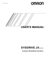
USER’S MANUAL
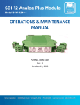
SYSDRIVE JX
SERIES
Compact Simplified Inverters
Thank you for choosing this SYSDRIVE 3G3JX-series product. Proper use
and handling of the product will ensure proper product performance, will
lengthen product life, and may prevent possible accidents.
Please read this manual thoroughly and handle and operate the product
with care.
1. To ensure safe and proper use of the OMRON Inverters, please read this USER’S
MANUAL (Cat. No. I558-E1) to gain sufficient knowledge of the devices, safety information, and precautions before actual use.
2. The products are illustrated without covers and shieldings for closer look in this
USER’S MANUAL. For actual use of the products, make sure to use the covers and
shieldings as specified.
3. This USER’S MANUAL and other related user’s manuals are to be delivered to the
actual end users of the products.
4. Please keep this manual close at hand for future reference.
5. If the product has been left unused for a long time, please inquire at our sales representative.
NOTICE
1. This manual describes the functions of the product and relations with other
products. You should assume that anything not described in this manual is
not possible.
2. Although care has been given in documenting the product, please contact your
OMRON representative if you have any suggestions on improving this manual.
3. The product contains potentially dangerous parts under the cover. Do not attempt
to open the cover under any circumstances. Doing so may result in injury or death
and may damage the product. Never attempt to repair or disassemble the product.
4. We recommend that you add the following precautions to any instruction manuals
you prepare for the system into which the product is being installed.
S Precautions on the dangers of high-voltage equipment.
S Precautions on touching the terminals of the product even after power has been
turned OFF. (These terminals are live even with the power turned OFF.)
5. Specifications and functions may be changed without notice in order to improve
product performance.
Items to Check Before Unpacking
Check the following items before removing the product from the package:
S Has the correct product been delivered (i.e., the correct model number and specifications)?
S Has the product been damaged in shipping?
S Are any screws or bolts loose?
Introduction
Introduction
Thank you for choosing the general-purpose Inverter 3G3JX. This User's Manual (hereinafter called
"this manual") describes the parameter setting methods required for installation/wiring and
operation of the 3G3JX model, as well as troubleshooting and inspection methods.
z This manual should be delivered to the actual end user of the product.
z After reading this manual, keep it handy for future reference.
z This manual describes the specifications and functions of the product as well as the relations
between them. You should assume that anything not described in this manual is not possible with
the product.
z Intended readers
This manual is intended for:
Those with knowledge of the workings of electricity (qualified electric engineers or the equivalent),
and also in charge of:
• Introducing the control equipment
• Designing the control system
• Installing and/or connecting the control equipment
• Field management
1
Read and Understand this Manual
Read and Understand this Manual
Please read and understand this manual before using the product. Please consult your OMRON representative
if you have any questions or comments.
Warranty and Limitations of Liability
WARRANTY
OMRON's exclusive warranty is that the products are free from defects in materials and workmanship for a
period of one year (or other period if specified) from date of sale by OMRON.
OMRON MAKES NO WARRANTY OR REPRESENTATION, EXPRESS OR IMPLIED, REGARDING
NON-INFRINGEMENT, MERCHANTABILITY, OR FITNESS FOR PARTICULAR PURPOSE OF THE
PRODUCTS. ANY BUYER OR USER ACKNOWLEDGES THAT THE BUYER OR USER ALONE HAS
DETERMINED THAT THE PRODUCTS WILL SUITABLY MEET THE REQUIREMENTS OF THEIR
INTENDED USE. OMRON DISCLAIMS ALL OTHER WARRANTIES, EXPRESS OR IMPLIED.
LIMITATIONS OF LIABILITY
OMRON SHALL NOT BE RESPONSIBLE FOR SPECIAL, INDIRECT, OR CONSEQUENTIAL
DAMAGES, LOSS OF PROFITS OR COMMERCIAL LOSS IN ANY WAY CONNECTED WITH THE
PRODUCTS, WHETHER SUCH CLAIM IS BASED ON CONTRACT, WARRANTY, NEGLIGENCE, OR
STRICT LIABILITY.
In no event shall the responsibility of OMRON for any act exceed the individual price of the product on
which liability is asserted.
IN NO EVENT SHALL OMRON BE RESPONSIBLE FOR WARRANTY, REPAIR, OR OTHER CLAIMS
REGARDING THE PRODUCTS UNLESS OMRON'S ANALYSIS CONFIRMS THAT THE PRODUCTS
WERE PROPERLY HANDLED, STORED, INSTALLED, AND MAINTAINED AND NOT SUBJECT TO
CONTAMINATION, ABUSE, MISUSE, OR INAPPROPRIATE MODIFICATION OR REPAIR.
2
Read and Understand this Manual
Application Considerations
SUITABILITY FOR USE
OMRON shall not be responsible for conformity with any standards, codes, or regulations that apply to
the combination of products in the customer's application or use of the products.
At the customer's request, OMRON will provide applicable third party certification documents identifying
ratings and limitations of use that apply to the products. This information by itself is not sufficient for a
complete determination of the suitability of the products in combination with the end product, machine,
system, or other application or use.
The following are some examples of applications for which particular attention must be given. This is not
intended to be an exhaustive list of all possible uses of the products, nor is it intended to imply that the
uses listed may be suitable for the products:
• Outdoor use, uses involving potential chemical contamination or electrical interference, or conditions
or uses not described in this manual.
• Nuclear energy control systems, combustion systems, railroad systems, aviation systems, medical
equipment, amusement machines, vehicles, safety equipment, and installations subject to separate
industry or government regulations.
• Systems, machines, and equipment that could present a risk to life or property.
Please know and observe all prohibitions of use applicable to the products.
NEVER USE THE PRODUCTS FOR AN APPLICATION INVOLVING SERIOUS RISK TO LIFE OR
PROPERTY WITHOUT ENSURING THAT THE SYSTEM AS A WHOLE HAS BEEN DESIGNED TO
ADDRESS THE RISKS, AND THAT THE OMRON PRODUCTS ARE PROPERLY RATED AND
INSTALLED FOR THE INTENDED USE WITHIN THE OVERALL EQUIPMENT OR SYSTEM.
PROGRAMMABLE PRODUCTS
OMRON shall not be responsible for the user's programming of a programmable product, or any
consequence thereof.
3
Read and Understand this Manual
Disclaimers
CHANGE IN SPECIFICATIONS
Product specifications and accessories may be changed at any time based on improvements and other
reasons.
It is our practice to change model numbers when published ratings or features are changed, or when
significant construction changes are made. However, some specifications of the products may be
changed without any notice. When in doubt, special model numbers may be assigned to fix or establish
key specifications for your application on your request. Please consult with your OMRON representative
at any time to confirm actual specifications of purchased products.
DIMENSIONS AND WEIGHTS
Dimensions and weights are nominal and are not to be used for manufacturing purposes, even when
tolerances are shown.
PERFORMANCE DATA
Performance data given in this manual is provided as a guide for the user in determining suitability and
does not constitute a warranty. It may represent the result of OMRON's test conditions, and the users
must correlate it to actual application requirements. Actual performance is subject to the OMRON
Warranty and Limitations of Liability.
ERRORS AND OMISSIONS
The information in this manual has been carefully checked and is believed to be accurate; however, no
responsibility is assumed for clerical, typographical, or proofreading errors, or omissions.
4
Safety Precautions
Safety Precautions
Indications and Meanings of Safety Information
In this user's manual, the following precautions and signal words are used to provide information to ensure the
safe use of the 3G3JX Inverter.
The information provided here is vital to safety. Strictly observe the precautions provided.
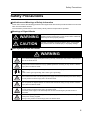
Meanings of Signal Words
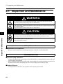
WARNING
Indicates an imminently hazardous situation which, if not avoided,
is likely to result in serious injury or may result in death. Additionally
there may be severe property damage.
CAUTION
Indicates a potentially hazardous situation which, if not avoided,
may result in minor or moderate injury or in property damage.
Alert Symbols in this Document
WARNING
Turn off the power supply and implement wiring correctly. Not doing so may result in a serious injury
due to an electric shock.
Wiring work must be carried out only by qualified personnel. Not doing so may result in a serious
injury due to an electric shock.
Be sure to ground the unit. Not doing so may result in a serious injury due to an electric shock or
fire.
(200-V class: type-D grounding, 400-V class: type-C grounding)
Do not remove the front cover during the power supply and 5 minutes after the power shutoff. Doing
so may result in a serious injury due to an electric shock.
Do not operate the Digital Operator or switches with wet hands. Doing so may result in a serious
injury due to an electric shock.
Inspection of the Inverter must be conducted after the power supply has been turned off. Not doing
so may result in a serious injury due to an electric shock.
The main power supply is not necessarily shut off even if the emergency shutoff function is
activated.
Do not change wiring, mode change switches (S7, S8), optional devices or replace cooling fans
while power is being supplied.
Doing so may result in a serious injury due to an electric shock.
5
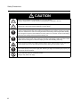
Safety Precautions
CAUTION
Do not connect resistors to the terminals (+1, P/+2, N/-) directly.
Doing so might result in a small-scale fire, heat generation or damage to the unit.
Install a stop motion device to ensure safety. Not doing so might result in a minor injury. (A holding
brake is not a stop motion device designed to ensure safety.)
Be sure to use a specified type of braking resistor/regenerative braking unit. In case of a braking
resistor, install a thermal relay that monitors the temperature of the resistor. Not doing so might
result in a moderate burn due to the heat generated in the braking resistor/regenerative braking
unit. Configure a sequence that enables the Inverter power to turn off when unusual overheating is
detected in the braking resistor/regenerative braking unit.
The Inverter has high voltage parts inside which, if short-circuited, might cause damage to itself or
other property. Place covers on the openings or take other precautions to make sure that no metal
objects such as cutting bits or lead wire scraps go inside when installing and wiring.
Do not touch the Inverter fins, braking resistors and the motor, which become too hot during the
power supply and for some time after the power shutoff. Doing so may result in a burn.
Take safety precautions such as setting up a molded-case circuit breaker (MCCB) that matches
the Inverter capacity on the power supply side. Not doing so might result in damage to property due
to the short circuit of the load.
Do not dismantle, repair or modify this product.
Doing so may result in an injury.
6
Precautions for Safe Use
Precautions for Safe Use
Installation and Storage
Do not store or use the product in the following places.
•Locations subject to direct sunlight.
•Locations subject to ambient temperature exceeding the specifications.
•Locations subject to relative humidity exceeding the specifications.
•Locations subject to condensation due to severe temperature fluctuations.
•Locations subject to corrosive or flammable gases.
•Locations subject to exposure to combustibles.
•Locations subject to dust (especially iron dust) or salts.
•Locations subject to exposure to water, oil, or chemicals.
•Locations subject to shock or vibration.
Transporting, Installation, and Wiring
•Do not drop or apply strong impact on the product. Doing so may result in damaged parts or malfunction.
•Do not hold by the front cover, but hold by the fins during transportation.
•Do not connect an AC power supply voltage to the control input/output terminals. Doing so may result in
damage to the product.
•Be sure to tighten the screws on the terminal block securely.
Wiring work must be done after installing the unit body.
•Do not connect any load other than a three-phase inductive motor to the U, V, and W output terminals.
•Take sufficient shielding measures when using the product in the following locations. Not doing so may
result in damage to the product.
Locations subject to static electricity or other forms of noise.
Locations subject to strong magnetic fields.
Locations close to power lines.
Operation and Adjustment
•Be sure to confirm the permissible range of motors and machines before operation because the Inverter
speed can be changed easily from low to high.
•Provide a separate holding brake if necessary.
Maintenance and Inspection
•Be sure to confirm safety before conducting maintenance, inspection or parts replacement.
7
Precautions for Correct Use
Precautions for Correct Use
Installation
•Mount the product vertically on a wall or on a DIN Rail (optional) with the product's longer sides upright.
The material of the wall has to be noninflammable such as a metal plate.
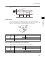
Main Circuit Power Supply
•Confirm that the rated input voltage of the Inverter is the same as AC power supply voltage.
Error Retry Function
•Do not come close to the machine when using the error retry function because the machine may abruptly
start when stopped by an alarm.
•Be sure to confirm the RUN signal is turned off before resetting the alarm because the machine may
abruptly start.
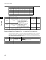
Non-Stop Function at Momentary Power Interruption
•Do not come close to the machine when selecting restart in the non-stop function at momentary power
interruption selection (b050) because the machine may abruptly start after the power is turned on.
Operation Stop Command
•Provide a separate emergency stop switch because the STOP key on the Digital Operator is valid only when
function settings are performed.
•When checking a signal during the power supply and the voltage is erroneously applied to the control input
terminals, the motor may start abruptly. Be sure to confirm safety before checking a signal.
Product Disposal
•Comply with the local ordinance and regulations when disposing of the product.
8
Precautions for Correct Use
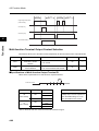
Warning Labels
Warning labels are located on the Inverter as shown in the following illustration.
Be sure to follow the instructions.
Warning Description
9
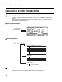
Checking Before Unpacking
Checking Before Unpacking
Checking the Product
On delivery, be sure to check that the delivered product is the Inverter 3G3JX model that you
ordered.
Should you find any problems with the product, immediately contact your nearest local sales
representative or OMRON sales office.
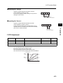
zChecking the Nameplate
Inverter model
Input specifications
Output specifications
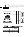
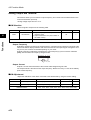
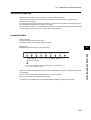
zChecking the Model
3 G 3 J X -A 2 0 0 2
Maximum applicable motor capacity
002
004
007
015
022
037
0.2 kW
0.4 kW
0.75 kW
1.5 kW
2.2 kW
3.7 kW
Voltage class
2
E
4
3-phase 200 V AC (200-V class)
1/3-phase 200 V AC (200-V class)
3-phase 400 V AC (400-V class)
Enclosure rating
A
Panel-mounting (IP10 min.) or closed
wall-mounting models
Checking the Accessories
Note that this manual is the only accessory included with the 3G3JX model.
Mounting screws and other necessary parts must be provided by the user.
10
Revision History
Revision History
A manual revision code appears as a suffix to the catalog number located at the
lower left of the front and back covers.
Cat. No. I558-E1-01
Revision code
Revision code
Revision date
01
December 2007
Changes and revision pages
First printing
11
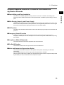
About This Manual
About This Manual
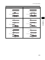
This User's Manual is compiled chapter by chapter for user's convenience as follows.
Understanding the following configuration ensures more effective use of the product.
Overview
12
Chapter 1 Overview
Describes features and names of parts.
Chapter 2 Design
Provides external dimensions, installation dimensions, peripheral device
design/selection instructions, and other information necessary for
design.
Chapter 3 Operation
Describes names of parts, the Inverter's operations, including how to use
the keys on the Digital Operator, and the monitor function.
Chapter 4 Functions
Describes the functions of the Inverter.
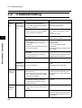
Chapter 5
Maintenance
Operations
Describes the causes and their countermeasures if the Inverter fails,
including the solutions to possible troubles (troubleshooting).
Chapter 6
Inspection and
Maintenance
Describes items for periodical inspection and/or maintenance for the
Inverter.
Chapter 7 Specifications
Provides Inverter specifications, as well as the specifications and
dimensions of peripheral devices.
Appendix
Describes the summarized parameter settings as a reference for users
who have used this Inverter and understood the functions.
Contents
Introduction..............................................................................................1
Read and Understand this Manual ..........................................................2
Safety Precautions ..................................................................................5
Precautions for Safe Use.........................................................................7
Precautions for Correct Use ....................................................................8
Checking Before Unpacking ....................................................................10
Revision History.......................................................................................11
About This Manual...................................................................................12
Chapter 1
1-1
1-2
Chapter 2
2-1
2-2
Chapter 3
3-1
3-2
3-3
3-4
3-5
3-6
3-7
Chapter 4
4-1
4-2
Chapter 5
5-1
5-2
Chapter 6
6-1
6-2
Chapter 7
7-1
7-2
Overview
Functions .................................................................................................1-1
Appearance and Names of Parts.............................................................1-3
Design
Installation................................................................................................2-1
Wiring.......................................................................................................2-5
Operation
Test Run Procedure.................................................................................3-3
Test Run Operation .................................................................................3-4
Part Names and Descriptions of the Digital Operator..............................3-9
Operation Procedure (Example: Factory Default)....................................3-11
Keys.........................................................................................................3-17
Parameter Transition ...............................................................................3-18
Parameter List .........................................................................................3-20
Functions
Monitor Mode...........................................................................................4-1
Function Mode .........................................................................................4-5
Maintenance Operations
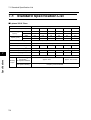
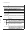
Special Display List..................................................................................5-1
Troubleshooting .......................................................................................5-5
Inspection and Maintenance
Inspection and Maintenance....................................................................6-1
Storage ....................................................................................................6-7
Specifications
Standard Specification List ......................................................................7-1
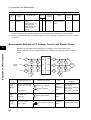
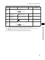
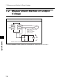
Measurement Method of Output Voltage.................................................7-5
13
Contents
7-3
7-4
7-5
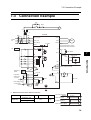
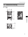
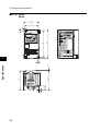
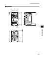
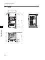
Connection Example ............................................................................... 7-6
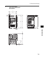
Dimensional Drawing .............................................................................. 7-8
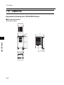
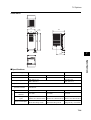
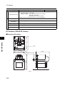
Options.................................................................................................... 7-13
Appendix
Appendix-1
Appendix-2
Appendix-3
Index
14
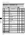
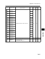
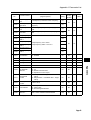
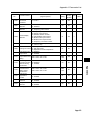
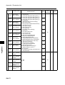
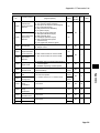
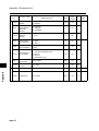
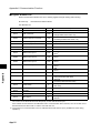
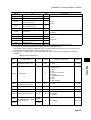
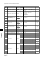
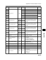
Parameter List ......................................................................... App-1
Communication Function ......................................................... App-17
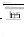
Product Life Curve ................................................................... App-45
Chapter 1
Overview
1-1 Functions .......................................................... 1-1
1-2 Appearance and Names of Parts .................... 1-3
1-1 Functions
1Overview
Overview
1
1-1 Functions
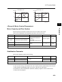
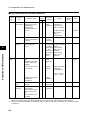
3G3JX Inverter Models
Rated voltage
Enclosure rating
Max. applicable motor capacity
Model
0.2 kW
3G3JX-A2002
0.4 kW
3G3JX-A2004
0.75 kW
3G3JX-A2007
1.5 kW
3G3JX-A2015
2.2 kW
3G3JX-A2022
3.7 kW
3G3JX-A2037
0.4 kW
3G3JX-A4004
0.75 kW
3G3JX-A4007
1.5 kW
3G3JX-A4015
2.2 kW
3G3JX-A4022
3.7 kW
3G3JX-A4037
0.2 kW
3G3JX-AE002
0.4 kW
3G3JX-AE004
0.75 kW
3G3JX-AE007
1.5 kW
3G3JX-AE015
2.2 kW
3G3JX-AE022
3-phase 200 V AC
3-phase 400 V AC
IP20
(Complies with
JEM1030)
1/3-phase 200 V AC
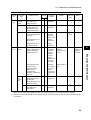
International Standards Models (EC Directives and UL/cUL Standards)
The 3G3JX Inverter meets the EC Directives and UL/cUL standard requirements for worldwide use.
Classification
Applicable standard
EMC Directive
EN61800-3: 2004
Low-voltage Directive
EN61800-5-1: 2003
EC Directives
UL/cUL Standards
1-1
UL508C
1-1 Functions
Compact Simplified Inverter for Customer's Environment and
Application Demands
1
Simple Wiring and Easy Installation
Wide Ranging Capacity and Power Supply
In spite of its compact size, the 3G3JX Inverter provides a wide ranging capacity from 0.2 to 3.7 kW.
Moreover, the three-phase 200 V, three-phase 400 V, and single/three-phase 200 V common types
are made to meet the power supply specifications for use outside Japan.
PID Function
The PID function is featured for the easier control of the fan and pump. It helps to control airflow and
pressure.
Emergency Shutoff Function
Switching the dedicated switch (S8) changes from the multi-function input (input 3) to the
emergency shutoff input. You can directly turn off a motor control power module without operating
the software.
Compliance With All Standards
The 3G3JX Series has achieved compliance with CE and UL/cUL.
The RoHS Directive
The standard model meets the requirements of the RoHS Directive.
Noise and Harmonics Suppression Option
The three-phase models incorporate a zero-phase reactor (radio noise filter) as a standard
specification.
For the single/three-phase common type, optional suppression is available.
When the optional DC reactor is added, the 3G3JX Series will also meet the requirements specified
by the Ministry of Land, Infrastructure and Transport of Japan.
1-2
Overview
The main circuit adopts upper/lower wiring as with a conductor. In addition, the side-by-side
mounting of the Inverters and the built-in zero-phase reactor contribute to space saving in control
panel.
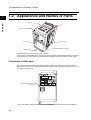
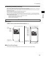
1-2 Appearance and Names of Parts
1
1-2 Appearance and Names of Parts
Overview
Top cover
Fin
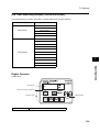
Digital Operator
Front cover
Main housing
FREQ (FREQUENCY) adjuster
Bottom cover
•The size of the fin varies with the motor capacity.
•There are two sizes depending on the motor capacity, but the fundamental structure is the same.
•Remove the front cover when connecting the power supply, the motor, and the control signal.
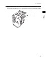
Connection to RJ45 Jack
Connect the communications cable after opening the cover of the communications connector.
Remove the front cover to switch communications. Refer to the next page for instructions on how
to remove the front cover.
8k8k8k8
Communications connector
(with cover)
*The cover of the communications connector is removable. Remove the front cover to attach it.
1-3
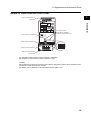
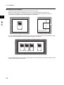
1-2 Appearance and Names of Parts
Names of Parts Inside the Front Cover
1
Main circuit terminal block
(input side)
Communications connector
Overview
8k8k8k8
Do not touch these!
(ELECTRICAL HAZARD:
For factory maintenance only)
Relay output terminal block
S7
485
OPE
Control circuit terminal block
S8
ON
OFF
Main circuit terminal block
(output side)
S7: OPE/485 communications selector (Default = OPE side)
S8: Emergency shutoff function selector (Default = OFF)
(Caution)
Do not switch the emergency shutoff function selector (S8) without reason as the allocation of the
multi-function input terminals may change.
For details, refer to "Emergency Shutoff Input Function" (page 4-43).
1-4
Chapter 2
Design
2-1 Installation ........................................................ 2-1
2-2 Wiring ................................................................ 2-5
2-1 Installation
2Design
2-1 Installation
2
Design
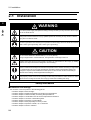
WARNING
Turn off the power supply and implement wiring correctly. Not doing so may result in a serious injury
due to an electric shock.
Wiring work must be carried out only by qualified personnel. Not doing so may result in a serious
injury due to an electric shock.
Be sure to ground the unit. Not doing so may result in a serious injury due to an electric shock or fire.
(200-V class: type-D grounding, 400-V class: type-C grounding)
CAUTION
Do not connect resistors to the terminals (+1, P/+2, N/-) directly.
Doing so might result in a small-scale fire, heat generation or damage to the unit.
Install a stop motion device to ensure safety. Not doing so might result in a minor injury. (A holding
brake is not a stop motion device designed to ensure safety.)
Be sure to use a specified type of braking resistor/regenerative braking unit. In case of a braking
resistor, install a thermal relay that monitors the temperature of the resistor. Not doing so might result
in a moderate burn due to the heat generated in the braking resistor/regenerative braking unit.
Configure a sequence that enables the Inverter power to turn off when unusual overheating is
detected in the braking resistor/regenerative braking unit.
The Inverter has high voltage parts inside which, if short-circuited, might cause damage to itself or
other property. Place covers on the openings or take other precautions to make sure that no metal
objects such as cutting bits or lead wire scraps go inside when installing and wiring.
Safety Information
Installation and Storage
Do not store or use the product in the following places.
•Locations subject to direct sunlight.
•Locations subject to ambient temperature exceeding the specifications.
•Locations subject to relative humidity exceeding the specifications.
•Locations subject to condensation due to severe temperature fluctuations.
•Locations subject to corrosive or flammable gases.
•Locations subject to exposure to combustibles.
•Locations subject to dust (especially iron dust) or salts.
•Locations subject to exposure to water, oil, or chemicals.
•Locations subject to shock or vibration.
2-1
2-1 Installation
Transporting, Installation, and Wiring
Precautions for Use
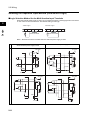
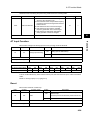
Installation
•Install the Inverter vertically on the wall or DIN tracks (optional).
Install the Inverter on a nonflammable wall surface material, like metal.
Position for installing a screw
Model
3G3JX-A2002
A2004
A2007
AE002
AE004
Screw size for
installation: M5
Position for installing a screw
Positions for installing screws
Model
3G3JX-A2015
A2022
A2037
A4004
A4007
A4015
A4022
A4037
AE007
AE015
AE022
Screw size for
installation: M5
Positions for installing screws
Main Circuit Power Supply
•Confirm that the rated input voltage of the Inverter matches the AC power supply voltage.
2-2
2
Design
•Do not drop or apply strong impact on the product. Doing so may result in damaged parts or malfunction.
•Do not hold by the front cover, but hold by the fins during transportation.
•Do not connect an AC power supply voltage to the control input/output terminals. Doing so may result in
damage to the product.
•Be sure to tighten the screws on the terminal block securely.
Wiring work must be done after installing the unit body.
•Do not connect any load other than a three-phase inductive motor to the U, V, and W output terminals.
•Take sufficient shielding measures when using the product in the following locations. Not doing so may
result in damage to the product.
Locations subject to static electricity or other forms of noise.
Locations subject to strong magnetic fields.
Locations close to power lines.
2-1 Installation
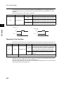
Installation Environment
•Increased ambient temperatures will shorten the life of the Inverter.
•Keep the Inverter away from heating elements (such as a braking resistor, DC reactor, etc.).
If the Inverter is installed in a control panel, keep the ambient temperature within the range of the
specifications, taking dimensions and ventilation into consideration.
2
Design
Airflow
Wall
•You can install multiple 3G3JX Inverters side by side in the control panel (side-by-side installation). Again,
keep the ambient temperature within the specified range (40°C or below).
•If the ambient temperature is from 40°C through to 50°C, the carrier frequency should be reduced and the
Inverter capacity should be increased.
2-3
2-1 Installation
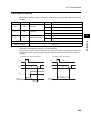
•Before installing the Inverter, place a cover over all the ventilation openings to shield them from foreign
objects.
After completing the installation process, be sure to remove the covers from the Inverter before operation.
2
Design
Ventilation openings
(Both sides and top)
2-4
2-2 Wiring
2-2 Wiring
2
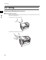
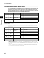
Removing and Mounting the Front Cover
Removing the Front Cover
Design
Loosen the mounting screw at the lower left of the front cover. Lift the bottom of the front cover to
remove while holding the body.
1. Loosen the front cover mounting screw.
2. Lift the bottom of the front cover to remove.
2-5
2-2 Wiring
Mounting the Front Cover
Hang the upper side of the front cover on the hooks, and push down both sides of the cover
simultaneously until it clicks into place.
1. Hang the upper side on the hooks. (Two hooks)
2
Design
2. Push down the cover until it clicks into place. (Both sides)
2-6
2-2 Wiring
Standard Connection Diagram
Braking unit
DC reactor
(optional)
2
Design
+1
P/+2
R/L1 (L1) *1
3-phase 200 V AC
1/3-phase 200 V AC *2
3-phase 400 V AC
N/U/T1
S/L2 (L2)
V/T2
T/L3 (N/L3)
W/T3
M
P24
PSC
Multi-function input 1
Multi-function input 2
Multi-function input 3
Multi-function input 4
Multi-function input 5
Sequence input common
Frequency reference power supply
Frequency
reference
(1 to 2 kΩ)
Frequency reference input (voltage)
Frequency reference common
Frequency reference input (current)
S1
S2
S3
MB
MA
MC
Relay output *3
Common
S4
S5
SC
FS
P1
Multi-function output
PC
Multi-function output common
AM
Analog monitor output
FV
FC
FI
*1. The items in parentheses indicate terminal symbols for 3G3JX-AE.
*2. Connect a single-phase 200-V AC input to terminals L1 and N/L3.
*3. By factory default, MA is set to NC contact, and MB to NO contact in the
relay output (MA, MB) selection (C036).
2-7
2-2 Wiring
Wiring to the Power Supply and Motor
(Example) 3G3JX-A2004
(Example) 3G3JX-A2037
Main circuit terminal block (input side)
Main circuit terminal block (input side)
2
Design
Main circuit terminal block (output side)
Power
supply
Main circuit terminal block (output side)
Power
supply Ground
Ground
R/L1 S/L2 T/L3
R/L1 S/L2 T/L3
N/- P/+2 +1
U/T1 V/T2 W/T3
U/T1 V/T2 W/T3 N/- P/+2 +1
Motor
earth
Motor
earth
Motor
Motor
•Do not connect the power supply other than to R/L1, S/L2, or T/L3.
•Do not remove the short-circuit bar between P/+2 and +1, except when a DC reactor is connected.
Note 1: Install an earth leakage breaker on the power supply input side.
(Select an earth leakage breaker having a larger high-frequency sensed current and avoid
unnecessary operation.)
If the wiring between the Inverter and the motor is too long (longer than 10 m), the thermal
relay may malfunction due to harmonics. Install an AC reactor on the Inverter output side,
or use a current sensor instead of the thermal relay.
2-8
2-2 Wiring
Note 2: Connect securely to the ground as specified (type-D grounding for 200-V class, and
type-C grounding for 400-V class). Do not share the grounding electrode with other strong
electrical devices.
Example of incorrect grounding
Design
2
Example of correct grounding
Inverter
Inverter
Inverter
Inverter
Inverter
Inverter
Ground bolt
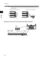
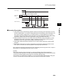
Wiring the Control Circuit Terminals and Relay Terminals
Relay
output
MB MA MC
Analog Frequency
monitor reference
output
input
Multi-function input
Multi-function
output
AM FS FV FI FC S5 S4 S3 S2 S1 SC PSC P24 PC P 1
Short-circuit bar
2-9
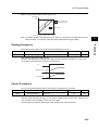
2-2 Wiring
Wiring Example of the Control Circuit Terminal Block (Sink Logic)
Multi-step speed reference 1
Reverse rotation RUN command
Forward rotation RUN command
External power supply
terminal for input signal
FI
Multi-step speed reference 2
FV
Reset input
FS
FC
S5
S4
S3
S2
S1
SC
2
Design
AM
Input common
At sink logic (NPN) : External power supply input
At source logic (PNP) : Power supply output
Note: By factory default, the input logic of the multi-function input terminal circuit is
set to the sink logic.
PSC
P24
PC
Short-circuit bar
(at sink logic
[when internal
power supply is
used])
Variable resistor
frequency reference
(1 to 2 k)
P1
RY
Frequency arrival signal
(27 V DC 50 mA max.)
Frequency meter
Note 1: When connecting a relay to the multi-function output terminal, install a surge-absorbing
diode in parallel with the relay. The output circuit can break down due to surge voltage when
the relay is switched on/off.
Note 2: Remove the short-circuit bar when the external power supply is used.
Note 3: For the signal line, use a twisted shield wire and apply the shield coating as illustrated
below. Keep the length to 20 m or less.
Perform insulating treatment.
Ground connection is not required.
Connect to the ground terminal of the Inverter.
Note 4: Keep the wiring away from the power cable of the main circuit and from the wiring on the
relay control circuit. (More than 10 cm apart)
2-10
2-2 Wiring
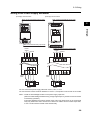
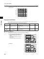
Selecting the Sequence Input Method (Sink/Source Logic)
Logic Selection Method for the Multi-function Input Terminals
When the internal power supply is used, you can switch the logic by rearranging the short-circuit bar
on the control circuit terminal block. The default setting is sink logic.
2
<Sink Logic>
Design
S1
<Source Logic>
SC PSC P24
S1
PC
SC PSC P24
PC
Short-circuit bar
Short-circuit bar
Note 1: Remove the short-circuit bar when the external power supply is used.
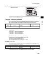
Inside the Inverter
When interface power supply is used
When external power supply is used
24 V DC
Sink logic
24 V DC
PSC
PCS
S1
S1
S5
S5
24 V DC
SC
COM
PLC etc.
SC
COM
PLC etc.
Inverter
Inverter
\
24 V DC
COM
24 V DC
P24
P24
S1
COM
Source logic
S1
S5
S5
24 V DC
PSC
PSC
SC
SC
PLC etc.
Inverter
PLC etc.
Inverter
2-11
2-2 Wiring
Wiring the Main Circuit Terminals
Connecting the Main Circuit Terminals
Wiring
Applicable Inverter model
0.2
3G3JX-A2002
3G3JX-A2004
0.4
Applicable device
Power cable
Earth leakage breaker
(ELB)
Fuse size
(class J)
Rated 600 V
1.25 mm2
(5 A)
10 A
1.25 mm2
(5 A)
10 A
3G3JX-A4004
3A
3G3JX-A2007
2.0 mm2
(10 A)
15 A
3G3JX-A4007
1.25 mm2
(5 A)
6A
3G3JX-A2015
2.0
mm2
(15 A)
15 A
3G3JX-A4015
2.0
mm2
(10 A)
10 A
3G3JX-A2022
2.0 mm2
(20 A)
20 A
3G3JX-A4022
2.0 mm2
(10 A)
10 A
3G3JX-A2037
mm2
(30 A)
30 A
2
(15 A)
15 A
0.75
1.5
2.2
3.5
3.7
3G3JX-A4037
2.0 mm
0.2
3G3JX-AE002
2.0 mm2
(5A)
14 A
0.4
3G3JX-AE004
2.0 mm2
(5 A)
3G3JX-AE007
2.0 mm
2
(10 A)
2
(15 A)
(20A)
0.75
1.5
3G3JX-AE015
5.5 mm
2.2
3G3JX-AE022
5.5 mm2
2
Design
Motor output
(kW)
•For the main circuit terminals, always use insulated electrical wires with a rated voltage of 600 V and a rated
temperature of 80°C or higher.
•Use the crimp-type terminal with an insulating sleeve to connect to the terminals.
•Up to two wires can be connected to one terminal.
•To prevent possible voltage drops, increase the wire size in accordance with the cable length.
•To connect the 100-V or 200-V model to the relay output terminal block, use a wire of 0.75 mm2.
•To connect seven wires or more to the control circuit terminal block, use a shield line of 0.5 mm2 or less.
•Strip the signal line by 5 to 6 mm, and connect the exposed wire. (In the case of stranded wires, make sure that
the wires are not unraveled.)
•Make sure that the maximum outside coating diameter of the signal line is 2.0 mm or less (except for the alarm
signal line). (For the mark tube mounted cable and multi-core cable, keep both the mark tube and the sheathstripped length 40 mm or more from the connecting end. A thick line may prevent proper closing of the cover of
the terminal block.)
•To meet UL standards, always insert a UL-standard fuse (J type) on the power supply side.
•Use a ground wire with a larger diameter than that of the power cable shown above.
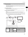
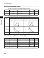
Choose the sensitivity current of the earth leakage breaker (ELB), depending on the total distance (L) between
the Inverter and the power supply, and the Inverter and the motor.
2-12
2-2 Wiring
Design
2
L
Sensitivity
current (mA)
100 m max.
30
300 m max.
100
800 m max.
200
Guide of leakage current: If a CV wire is used and routed through a metal pipe,
the leakage current is 30 mA/km.
Due to the higher specific inductive capacity of the H-IV wire, the leakage current
increases about eight times. Use a wire with a sensitivity current one-level higher.
The leakage current mentioned here is the effective value of the fundamental
wave, and high-frequency currents are excluded.
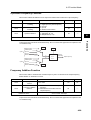
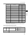
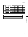
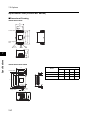
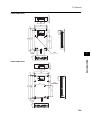
Terminal Arrangement
Main circuit terminal block
Type
Screw size
D (mm)
7.1
Upper side of the body
R/L1
S/L2
T/L3
A2002 to A2007
AE002 to AE004
(*1)
Lower side of the body
N/-
P/+2
+1
M3.5
7.1
Main Circuit
Terminal Block
U/T1 V/T2 W/T3
9.2
Upper side of the body
R/L1 S/L2 T/L3
A2015 to A2037
A4004 to A4037
AE007 to AE022
(*1)
Lower side of the body
U/T1 V/T2 W/T3
N/-
P/+2
+1
M4
9.2
Main Circuit
Terminal Block
*1. For 3G3JX-AE, R/L1 corresponds to L1, S/L2 to L2, and T/L3 to N/L3.
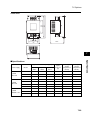
Relay Output
Terminal Block
MB
MA
Type
Main circuit
Control circuit
Relay
Ground
2-13
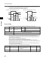
Control Circuit Terminal Block
MC
AM FS
FV
A2002 to A2007
AE002 to AE004
FI
FC S5 S4
S3 S2 S1 SC PSC P24 PC P1
A2015 to A2037
A4004 to A4037
AE007 to AE022
Screw size
D (mm)
Screw size
D (mm)
M3.5
7.1
M4
9.2
M2
M2
M2.5
M2.5
M4
M4
2-2 Wiring
Screw Tightening Torque
Screw
Tightening torque
M2
0.2 N•m (max. 0.25 N•m)
0.5 N•m (max. 0.6N•m)
M3.5
0.8 N•m (max. 0.9 N•m)
M4
1.2 N•m (max. 1.3 N•m)
2
Design
M2.5
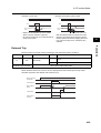
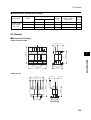
Explanation of the Main Circuit Terminal Connection
Terminal
symbol
Terminal name
R/L1, S/L2,
T/L3 *
Main power supply
input terminal
U/T1,
Inverter output
V/T2, W/T3 terminal
Function
Connection example
Connect the input power supply.
Connect to the motor.
Motor
Normally connected by the short-circuit
bar. Remove the short-circuit bar
between +1 and P/+2 when a DC reactor
is connected.
+1,
P/+2
External DC reactor
terminal
P/+2, N/-
Regenerative
Connect optional regenerative braking
braking unit
units.
connection terminal (If a braking torque is required)
Ground terminal
Ground (Connect to ground to prevent
electric shock and reduce noise.)
ELB
Power supply
Do not remove the short-circuit bar
between +1 and P/+2 when a DC
reactor is not connected.
* For 3G3JX-AE's terminal symbols, R/L1 corresponds to L1, S/L2 to L2, and T/L3 to N/L3.
Main Circuit Connection Diagram
Molded case
circuit-breaker
(MCCB)
Regenerative braking unit
MC
AC reactor
noise filter
Fuse
R/L1
Power supply
S/L2
T/L3 *
P/+2
N/-
U/T1
V/T2
M
W/T3
Inverter
3G3JX
2-14
2-2 Wiring
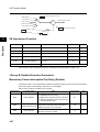
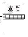
Wiring the Main Circuit Terminals (Input Side)
Installing a Molded-case Circuit Breaker (MCCB)
•Always connect the Inverter and power supply via a molded-case circuit breaker (MCCB) to protect
the Inverter from damage that may result from short-circuiting.
•Always connect the power input terminals (R/L1, S/L2, and T/L3) and power supply via an MCCB,
according to the Inverter capacity.
•Install one MCCB per Inverter.
•Choose an appropriate MCCB capacity according to the fuse size on page 2-12.
•When choosing an MCCB's time characteristics, be sure to consider the Inverter's overload
protection (1 minute at 150% of the rated output current).
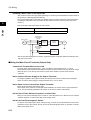
•By programming the sequence as illustrated below, you can turn off the power via the relay outputs
(MA, MB, and MC) for the 3G3JX Series.
Design
2
Molded-case
circuit breaker
(MCCB)
MC
X1
R/L1
Inverter
3G3JX
S/L2
T/L3 *
Power supply
X1
X2
MA
(30 V DC, 50 mA max.)
MC
X2
OFF
ON
X1
DC (24 V) relay
Installing a Ground Fault Interrupter
•The Inverter's output uses high-speed switching, and so generates high-frequency current
leakage. (Generally, if the power cable is 1 m, the leakage current is approx. 100 mA per Inverter,
and approx. 5 mA is added per additional meter of the power cable.)
•At the power supply input part, install a special-purpose ground fault interrupter for Inverters that
exclude high-frequency leakage current and detect only the leakage current within a frequency
range that is hazardous to humans. (Choose a ground fault interrupter with a sensitivity current of
at least 10 mA per Inverter.)
•Alternatively, use a general ground fault interrupter with a sensitivity current of 200 mA or more per
Inverter, and with an operating time of 0.1 s or more.
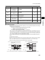
Installing a Magnetic Contactor (MC)
•If the power supply of the main circuit is shut off due to sequencing, a magnetic contactor (MC) can
be used. (When forcibly stopping the load with an MC on the primary side of the main circuit,
however, the regenerative braking does not work and the load coasts to a stop (free run).)
•Frequently opening and closing the magnetic contactor (MC) to start and stop a load may cause
the Inverter to break down. To extend the life of the Inverter's internal electrolytic capacitor, limit
the frequency to no more than once every 30 minutes.
Connection Sequence to the Terminal Block
•Input power supply can be connected to any terminal because the phase sequence of the input
power supply is irrelevant to that of the terminal block (R/L1, S/L2, and T/L3).
2-15
2-2 Wiring
Installing an AC Reactor
•If the Inverter is connected to a large-capacity power transformer (660 kVA or more) or the phase
advance capacitor is in use, a large peak current may flow through the input power circuit, causing
the converter unit to break down.
•Install an optional AC reactor on the input side of the Inverter. An AC reactor will also improve the
power factor of the power input side.
2
Installing a Surge Absorber
Connecting a Regenerative Braking Unit
When running a load with a large inertia or a vertical axis, regenerative energy will return to the
Inverter.
If overvoltage in the main circuit is generated during deceleration, this indicates that the
regenerative energy exceeds the capacity of the Inverter. In this case, use a regenerative braking
unit.
•When using a regenerative braking unit, be sure to include a sequence whereby the power supply
for the Inverter will be turned off in the event of abnormal overheating. Doing so may result in fire.
For a regenerative braking unit: Use the error contact output (MA, MB).
Molded-case
circuit breaker
(MCCB)
Magnetic contactor
(MC)
MC
Inverter
3G3JX
R/L1 (L1) *
S/L2 (L2)
T/L3 (N/L3)
Power supply
XB
OFF
ON
MC
MA
SA
N/-
P/+2
N
P
DCL
DC reactor
MB
MC
+1
P RB R1 R2
MC
Regenerative braking unit
SA
* For 3G3JX-AE's terminal symbols, R/L1 corresponds to L1, S/L2 to L2, and T/L3 to N/L3.
<Braking Resistors and Braking Resistor Units for the Inverter>
Name
Model
Specifications
For general use (with built-in resistor)
3G3AX-RBU21
Regenerative
braking unit
3G3AX-RBU22
3G3AX-RBU41
3/1-phase
200 V
3-phase
400 V
For heavy instantaneous regenerative power
(with built-in resistor)
For general use (with built-in resistor)
2-16
Design
•Always use a surge absorber or diode when magnetic contactors (MC), electromagnetic relays,
solenoid valves, solenoid, and magnetic brakes are used.
2-2 Wiring
Installing a Noise Filter on the Input Side
•The Inverter's output uses high-speed switching, so noise may be transmitted from the Inverter to
the power line, affecting peripheral devices.
•It is recommended that a noise filter be installed on the input side to minimize noise transmission.
(Installing a noise filter on the input side can also reduce the noise from the power line to the
Inverter.)
2
Design
<Recommended Input Noise Filters for the Inverter>
General
EMC-conforming
3G3AX-NFI
3G3AX-EFI
Power supply
Molded-case
circuit breaker
(MCCB)
Input noise
filter for
Inverter *
Inverter
3G3JX
M
Molded-case
circuit breaker
(MCCB)
Other device
* Use a noise filter designed for Inverters. A general-purpose noise filter will be less effective and
may not reduce noise.
Wiring the Main Circuit Terminals (Output Side)
Connect the Terminal Block to the Load
•Connect motor output terminals U/T1, V/T2, and W/T3 to motor lead wires U, V, and W.
•Check that the motor rotates forward with the forward command. Switch over any two of the output
terminals (U/T1, V/T2, W/T3) and reconnect if the motor rotates in reverse to the forward
command.
Never Connect a Power Supply to the Output Terminals
•If voltage is applied to the output terminals, the internal circuit of the Inverter will be damaged.
Never connect a power supply to output terminals U/T1, V/T2, or W/T3.
Never Short-circuit or Ground the Output Terminals
•Never touch the output terminals by hand.
•If the output wires come into contact with metal materials, an electric shock or ground fault will
occur. This is extremely hazardous. Be careful not to short-circuit the output wires.
Do Not Use a Phase Advance Capacitor or Noise Filter
•Doing so may result in damage to the Inverter or cause the parts to burn. Never connect a phase
advance capacitor or LC/RC noise filter to the output circuit.
Do Not Use an Electromagnetic Switch
•If a load is connected to the Inverter during running, an inrush current will actuate the overcurrent
protective circuit in the Inverter. Do not connect an electromagnetic switch or magnetic contactor
(MC) to the output circuit.
2-17
2-2 Wiring
Install a Noise Filter on the Output Side
Connect a noise filter to the output side of the Inverter to reduce induction and radio noise.
Power
supply
Molded-case circuit breaker
(MCCB)
Inverter
3G3JX
Noise filter
3G3AX-NFO
Controller
Design
Induction noise
Signal line
2
M
Radio noise
AM radio
Induction noise: Electromagnetic induction can generate noise on the signal line, causing the
controller to malfunction.
Radio noise:
Electromagnetic waves from the Inverter and I/O cables can cause the radio receiver
to generate noise.
Countermeasures Against Induction Noise
To reduce induction noise from the output side, the following method is also effective.
•Run the cables collectively through the mounted metal pipe. Keeping the metal pipe at least 30 cm
away from the signal line reduces induction noise.
Power
supply
Molded-case circuit breaker
(MCCB)
Inverter
3G3JX
M
30 cm min.
Signal line
Controller
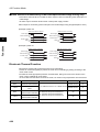
Cable Length Between Inverter and Motor
Use a cable of 50 m or less between the Inverter and the motor. If the cable length is increased, the
stray capacitance between the Inverter outputs and the ground is increased proportionally. An
increase in stray capacitance causes high-frequency leakage current to increase, affecting the
current detector in the Inverter's output unit and peripheral devices. If your system configuration
requires a cable length of 50 m or more, perform the following:
•Wire in metallic ducts.
•Use separate cables for each phase.
•Set the Inverter to a lower carrier frequency (b083).
Do Not Use Single-phase Motors
•A single-phase motor uses the capacitor start method or split-phase start method to determine its
rotation direction at startup, and thus is not suitable for the variable speed control via the Inverter.
Do not use single-phase motors.
* If a capacitor start motor is used, the capacitor may be damaged by a sudden electric charge and
discharge caused by Inverter output. If a split-phase start motor is used, the startup coil may burn
because the centrifugal switch does not operate.
2-18
2-2 Wiring
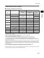
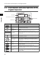
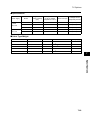
Specifications of Control Circuit Terminals
Design
2
Terminal
symbol
Terminal name and function
PSC
External power supply terminal for input
signal (input).......................At sink logic
Internal power supply output terminal for
input signal (output)......At source logic
Multi-function input terminals S1 to S5
Forward/Stop
S2
Select 5 functions among the 31
functions and allocate them to from
terminals S1 to S5.
Reverse/Stop
S3
Emergency stop
fault
SC
Input signal common
AM
Analog frequency monitor/
Analog output current monitor
FS
Frequency reference power supply
S5
24 V DC ±10%
30 mA max.
24 V DC ±10%
100 mA max.
Contact input
Close: ON (Start)
Open: OFF (Stop)
Minimum ON time:
12 ms min.
Multi-step speed
reference 1
Analog
frequency
monitor
10 V DC
10 mA max.
FV
Voltage frequency reference signal
FI
Current frequency reference signal
4 to 20 mA DC
Input impedance 250 Ω
FC
Frequency reference common
P1
Multi-function output terminal
Select the status of the Inverter and
allocate it to terminal P1.
Frequency
arrival signal at
a constant
speed
PC
Output signal common
MA
MB
MA
MC
MB
MC
Under normal operation : MA-MC Closed
Under abnormal operation or power
shutdown
: MA-MC Open
(Default)
2-19
Specifications
0 to 10 V DC
Input impedance 10 kΩ
When installing variable
resistors at FS, FV, and FC
(1 to 2 kΩ)
Output signal
Relay output
signal
Fault reset
The terminal allocation is changed
automatically when the emergency
shutoff function is used. Refer to
"Emergency Shutoff Input Function"
(page 4-43).
S4
Frequency
reference
input
S1
Input signal
Monitor
signal
Default setting
27 V DC
50 mA max.
Contact ratings
250 V AC 2.0 A (resistance load) 100 V AC min.
0.2 A (inductive load) 10 mA
30 V DC 3.0 A (resistance load) 5 V DC
0.6 A (inductive load) 100 mA
2-2 Wiring
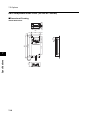
Functions of the Control Circuit Terminals
Terminal
function
Contact
input
(for
switching
function)
Terminal
symbol
Select functions and allocate them to terminals S1 to S5.
(The figure below illustrates the wiring of the sink logic.)
P24
Internal 24 V DC 24 V DC output
SC
Input common
Input signal common
Input power
supply
If the multi-function input is set as the sink logic, the PSC
terminal acts as an external power supply input terminal.
If the multi-function input terminal is set as the source logic,
the PSC terminal acts as an internal power supply output
terminal.
FV
FI
FC
reference Input
(Voltage
directive)
S4
S3
S2
2
S1
Frequency
reference
common
P1
Multi-function
output *2
MA
MB
Relay output
MC
Relay output
common
0 to 9.8 V DC
(Nominal input: 10 V)
Input impedance 10 Ω
FS FV FI FC
+
PC
P1
Shield wire
of 0.14 to
0.75 mm2
Recomme
nded wire
size:
0.75 mm2
-
4 to 19.6 mA DC
(Nominal input: 20 mA)
• Choose from frequency or output current.
Output terminal specifications
0 to 10 V DC full-scale
1 mA max.
RY
Multi-function
output common
-
+
Variable resistor
(1/2 W min.)
1 to 2 kΩ
Frequency
reference Input
(Current
directive)
Multi-function
analog output
PC
S5
Frequency
• External voltage directive is 0 to 9.8 V.
reference power
(Nominal input: 10 V) *1
supply output
FS FV FI FC
FS FV FI FC
Frequency
AM
Open
Collector
Output
SC
Design
FS
Relay
output
Wire size
Multi-function
input
PSC
Monitor
output
Function and connecting method
S1
S2
S3
S4
S5
Power
supply
External
analog
frequency
reference
Terminal name
AM
SC
Output terminal specifications
Open collector output
27 V DC max.
50 mA max.
Select the status of the Inverter and allocate it to terminal P1.
Selection of functions is the same as the multi-function
output.*3 *4
*1. Simultaneous input of current and voltage is not possible. Do not connect the signal lines simultaneously.
*2. By factory default, multi-function output P1 is set to NO contact.To switch to NC contact, change the C031
setting.
2-20
2-2 Wiring
*3. Below are the contact specifications of the relay output.
Output
terminal
2
Contact
capacity
Resistance load
Inductive load
Max.
250 V AC 2.5 A
30V DC 3 A
250 V AC 0.2 A
30 V DC 0.7 A
MA-MC
100 V AC 10 mA
5 V DC 100 mA
Min.
250 V AC 1 A
30 V DC 1 A
Design
Max.
250 V AC 0.2 A
30 V DC 0.2 A
MB-MC
100 V AC 10 mA
5 V DC 100 mA
Min.
*4. By factory default, the relay output (MA, MB) contact selection (C036) is set at NC contact between MA-MC, and
NO contact between MB-MC.
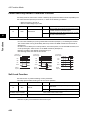
Mode Selector
RS-485 Communication/Operator Selector (S7)
Select the mode according to the option connected to the communications connector.
When using the 3G3AX-OP01 supplied with the Inverter, it is available regardless of the switch
condition.
Symbol
Name
Status
RS-485 communication/
operator selector
485
S7
OPE [Default]
Description
RS485 Modbus communication
Digital Operator (Option: 3G3AX-OP1)
Emergency shutoff selector (S8)
Use this selector to enable the emergency shutoff input function.
Symbol
Name
Status
ON
S8
Emergency
shutoff
selector
OFF
[Default]
Description
Emergency shutoff input enabled *1
Normal
*1 The multi-function input terminal 3 is switched to a terminal for emergency shutoff input, and the allocation of
other multi-function input terminals is also changed automatically. Do not set to ON immoderately. For details,
refer to "Emergency Shutoff Input Function" (page 4-43).
2-21
2-2 Wiring
Conforming to EC Directives
Conforming Standards
•EMC directive EN 61800-3
•Low-voltage directiveEN 61800-5-1
2
Concept of Conformity
OMRON products are the electrical devices incorporated and used in various machines or
manufacturing equipment. For this reason, we make efforts to conform our products to their related
EMC standards so that the machines or equipment which have incorporated our products should
easily conform to the EMC standards. The 3G3JX models have conformed to the EMC directive EN
61800-3 by following the installation and wiring method as shown below. Your machines or
equipment, however, vary in type, and in addition, EMC performance depends on the configuration,
wiring, or location of the devices or control panels which incorporate the EC directive conforming
products. This in turn does not allow us to confirm the condition and the conformity in which our
products are used. Therefore, we appreciate confirmation of the final EMC conformity for the whole
machine or equipment on your own.
Wiring the Power Supply
•Be sure to connect the power input terminals (R/L1, S/L2, and T/L3) and power supply via an EMC
conforming dedicated noise filter 3G3AX-EFI.
•Keep the ground cable as short as possible.
•Keep the cable between the Inverter and the noise filter as short as possible.
Connecting a Motor to the Inverter
•When connecting a motor to the Inverter, be sure to use shielded braided cables.
•Keep the cables as short as possible.
Low-voltage Directive
The 3G3JX models have conformed to the EMC directive EN61800-5-1 by performing the machine
installation and wiring as shown below.
•The 3G3JX models are an open type device. Be sure to install it inside the control panel.
•The power supply and voltage (SELV) with reinforced or double insulation should be used for
wiring to the control circuit terminals.
•To satisfy requirements of the LVD (low-voltage) directive, the Inverter must be protected with a
molded case circuit breaker (MCCB) in case a short-circuiting accident occurs. Be sure to install a
molded case circuit breaker (MCCB) on the power supply side of the Inverter.
•Use one molded case circuit breaker (MCCB) per Inverter.
•Use the crimp-type terminal with an insulation sleeve to connect to the main circuit terminals.
•When not using the braking resistor or braking resistor unit, connect the crimp-type terminal with
an insulation sleeve to the braking resistor connection terminals (P/+2, N/-).
2-22
Design
EMC Directive
Chapter 3
Operation
3-1 Test Run Procedure ......................................... 3-3
3-2 Test Run Operation.......................................... 3-4
3-3 Part Names and Descriptions of the Digital
Operator ............................................................ 3-9
3-4 Operation Procedure (Example: Factory Default)
........................................................................... 3-11
3-5 Keys................................................................... 3-17
3-6 Parameter Transition ....................................... 3-18
3-7 Parameter List .................................................. 3-20
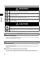
3Operation
WARNING
Do not remove the front cover during the power supply and 5 minutes after the power shutoff.
Doing so may result in a serious injury due to an electric shock.
Do not operate the Digital Operator or switches with wet hands. Doing so may result in a serious
injury due to an electric shock.
3
Operation
Inspection of the Inverter must be conducted after the power supply has been turned off. Not doing
so may result in a serious injury due to an electric shock.
The main power supply is not necessarily shut off even if the emergency shutoff function is activated.
Do not change wiring, mode change switches (S7, S8), optional devices or replace cooling fans while
power is being supplied.
Doing so may result in a serious injury due to an electric shock.
CAUTION
Do not touch the Inverter fins, braking resistors and the motor, which become too hot during the
power supply and for some time after the power shutoff. Doing so may result in a burn.
Take safety precautions such as setting up a molded-case circuit breaker (MCCB) that matches the
Inverter capacity on the power supply side. Not doing so might result in damage to property due to
the short circuit of the load.
Safety Information
Operation and Adjustment
•Be sure to confirm the permissible range of motors and machines before operation because the Inverter
speed can be changed easily from low to high.
•Provide a separate holding brake if necessary.
Precautions for Use
Error Retry Function
•Do not come close to the machine when using the error retry function because the machine may abruptly
start when stopped by an alarm.
•Be sure to confirm the RUN signal is turned off before resetting the alarm because the machine may
abruptly start.
Non-Stop Function at Momentary Power Interruption
•Do not come close to the machine when selecting restart in the non-stop function at momentary power
interruption selection (b050) because the machine may abruptly start after the power is turned on.
3-1
Operation Stop Command
•Provide a separate emergency stop switch because the STOP key on the Digital Operator is valid only when
function settings are performed.
•When checking a signal during the power supply and the voltage is erroneously applied to the control input
terminals, the motor may start abruptly. Be sure to confirm safety before checking a signal.
3
Operation
3-2
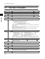
3-1 Test Run Procedure
3-1 Test Run Procedure
Item
Description
Reference page
Installation and Mounting Install the Inverter according to the installation conditions.
2-1
•Make sure that the installation conditions are met.
3
Wiring and Connection
Connect to the power supply and peripheral devices.
2-5
Operation
•Select peripheral devices that meet the specifications, and wire correctly.
Power On
Check the following before turning on the power.
•Make sure that an appropriate power supply voltage is supplied and that the power input
terminals (R/L1, S/L2, and T/L3) are wired correctly.
3G3JX-A2: 3-phase 200 to 240 V AC
3G3JX-AE: 1/3-phase 200 to 240 V AC
(Connect to L1 and N/L3 for 1 phase)
3G3JX-A4: 3-phase 380 to 480 V AC
•Make sure that the motor output terminals (U/T1, V/T2, and W/T3) are connected to the
motor correctly.
•Make sure that the control circuit terminals and the control device are wired correctly
and that all control terminals are turned off.
•Set the motor to no-load status (i.e., not connected to the mechanical system).
•After checking the above, turn on the power.
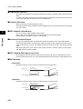
Display Status Check
Make sure that there are no faults in the Inverter.
•When the power is turned on normally, the display shows:
RUN LED indicator
: ON
ALARM LED indicator
: OFF
POWER LED indicator : ON
RUN command LED indicator : ON
Volume LED indicator : ON
Data LED indicator (frequency) : ON
Data display
: Displays the set value in d001.
•If an error occurs, the error code is displayed on the data display. In this case, refer to
"Chapter 5 Maintenance Operations" and make the necessary changes to remedy.
Parameter Initialization
Initialize the parameters.
•Set parameter No. b084 to "02", and press the
keys simultaneously.
Parameter Settings
key while holding down the
and
Set the parameters required for a test run.
•Set the motor capacity selection (H003) and the motor pole number selection (H004).
No-load Operation
Start the no-load motor via the Digital Operator.
•Use the FREQ adjuster on the Digital Operator to rotate the motor.
Actual Load Operation
Connect the mechanical system and operate via the Digital Operator.
•If there are no difficulties with the no-load operation, connect the mechanical system to
the motor and operate via the Digital Operator.
Operation
3-3
Refer to "Chapter 4 Functions", and set the necessary parameters.
3-2 Test Run Operation
3-2 Test Run Operation
Power On
Checkpoints Before Turning On the Power
Power On
•After checking the above, turn on the power.
Display Status Check
•When the power is turned on normally, the display shows:
[Normal] RUN LED indicator (during RUN)
POWER LED indicator
Volume LED indicator
Data display
: ON
ALARM LED indicator
: OFF
: ON
RUN command LED indicator : ON
: ON
Data LED indicator (frequency) : ON
: Displays the set value in d001
•If an error occurs, refer to "Chapter 5 Maintenance Operations" and make the necessary changes
to remedy.
[Fault]
RUN LED indicator (during RUN) : ON
ALARM LED indicator
: ON
POWER LED indicator
: ON
RUN command LED indicator : ON
Volume LED indicator
: ON
Data LED indicator (frequency) : ON
Data display
: An error code, such as "E-01", is displayed.
(The display varies depending on the type of error.)
3-4
3
Operation
•Make sure that an appropriate power supply voltage is supplied and that the power input terminals
(R/L1, S/L2, and T/L3) are wired correctly.
3G3JX-A2: 3-phase 200 to 240 V AC
3G3JX- AE: 1/3-phase 200 to 240 V AC (Connect to L1 and N/L3 for 1 phase)
3G3JX-A4: 3-phase 380 to 480 V AC
•Make sure that the motor output terminals (U/T1, V/T2, and W/T3) are connected to the motor
correctly.
•Make sure that the control circuit terminals and the control device are wired correctly and that all
control terminals are turned off.
•Set the motor to no-load status (i.e., not connected to the mechanical system).
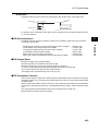
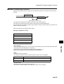
3-2 Test Run Operation
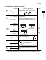
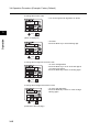
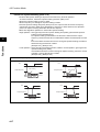
Parameter Initialization
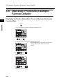
•Initialize the parameters using the following procedure.
•To initialize the parameters, set parameter b084 to "02".
Key sequence
Display example
k0.0
Operation
3
Description
Power On
bk-k-k-
Press the Mode key once, and then press the Decrement key three
times to display "b---".
bk0k0k1
Press the Mode key.
"b001" is displayed.
bk0k8k4
Use the Increment or Decrement key to display "b084".
0k0
Press the Mode key. The set value in "b084" is displayed.
0k2
Use the Increment or Decrement key to display "02".
bk0k8k4
Press the Enter key. The set value is entered and "b084" is displayed.
Press the STOP/RESET key while holding down the Mode and
Decrement keys simultaneously.
When the display blinks, release the STOP/RESET key first, and then
the Mode and Decrement keys.
=k.k0k0
(In 1 s)
3-5
dk0k0k1
Displays initialization.
The parameter number is displayed again in approximately 1 s.
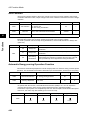
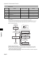
3-2 Test Run Operation
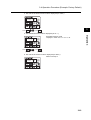
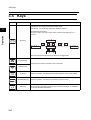
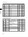
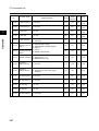
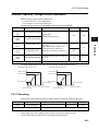
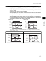
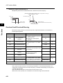
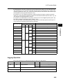
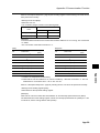
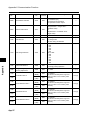
Setting the Motor Capacity Selection (H003) and Motor Pole Number Selection
(H004)
Parameter
No.
Register
No.
Name
Setting range
Unit of
setting
Default
setting
Interrupt
during
RUN
kW
Varies
with the
capacity.
No
Pole
4
No
H003
1165h
Motor
capacity
selection
Sets the capacity of the
motor connected to the
Inverter.
200-V class
0.2/0.4/0.75/
1.5/2.2/3.7/
5.5/7.5
400-V class
0.4/0.75/1.5/
2.2/3.7/5.5/7.5
H004
1166h
Motor pole
number
selection
Sets the pole number of
the motor connected to
the Inverter.
2/4/6/8
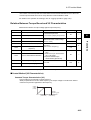
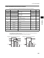
Key sequence
(In approx. 1 s)
Display example
Description
bk-k-k-
Press the Mode key twice to display the mode selection.
hk-k-k-
Use the Increment or Decrement key to display "H---".
hk0k0k3
Press the Mode key. "H003" is displayed.
0.2k0
Press the Mode key. The set value in "H003" is displayed.
0.4k0
Use the Increment or Decrement key to set the rated motor capacity.
0.4k0
Press the Enter key. The set value is entered.
hk0k0k3
The parameter number is displayed again.
3-6
3
Operation
Description
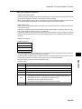
3-2 Test Run Operation
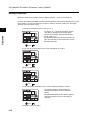
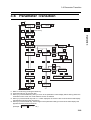
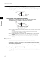
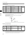
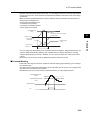
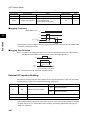
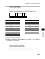
No-load Operation
•Start the no-load motor (i.e., not connected to the mechanical system) using the Digital Operator.
* Before operating the Digital Operator, check that the FREQ adjuster is set to "MIN."
* Make sure that the LED indicator above the FREQ adjuster and the RUN command LED indicator
are lit.
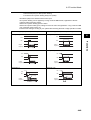
Forward/Reverse Rotation via the Digital Operator
3
Key sequence
Display example
Operation
0.0
0.0
1k0.0k0
Description
Press and hold the Mode key for 3 seconds or more to display "d001",
and then press again.
(Monitors the frequency reference.)
Press the RUN key.
The RUN command LED indicator is lit.
Turn the FREQ adjuster slowly.
The monitor value of the frequency reference is displayed.
The motor starts rotating forward in accordance with the frequency
reference.
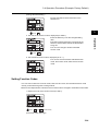
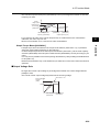
•By turning the FREQ adjuster, make sure that there is no vibration or abnormal sound from the
motor.
•Make sure that no errors have occurred in the Inverter during operation.
•Switch between forward and reverse with the operator rotation direction selection (F004).
Stopping the Motor
•After completing the no-load operation, press the STOP/RESET key. The motor will stop.
Actual Load Operation
•After checking the operation with the motor in the no-load status, connect the mechanical system
and operate with an actual load.
* Before operating the Digital Operator, check that the FREQ adjuster is set to "MIN."
Connecting the Mechanical System
•After confirming that the motor has stopped completely, connect the mechanical system.
•Be sure to tighten all the screws when fixing in the motor axis.
Operation via the Digital Operator
•Because a possible error may occur during operation, make sure that the STOP/RESET key on
the Digital Operator is easily accessible.
•Use the Digital Operator to operate the Inverter the same way as in no-load operation.
3-7
3-2 Test Run Operation
Checking the Operating Status
•After making sure that the operating direction is correct and that the Inverter is operating smoothly
at a slow speed, increase the frequency reference.
•By changing the frequency reference or the rotation direction, make sure that there is no vibration
or abnormal sound from the motor.
Make sure that the output current (output current monitor [d002]) is not excessive.
3
Operation
3-8
3-3 Part Names and Descriptions of the Digital Operator
3-3 Part Names and Descriptions of the
Digital Operator
3
Data display
Operation
RUN command LED indicator
FREQ adjuster
Operation keys
Name
8k8k8k8
3-9
Description
POWER LED indicator
Lit when the power is supplied to the control circuit.
ALARM LED indicator
Lit when an Inverter error occurs.
RUN (during RUN) LED
indicator
Lit when the Inverter is running.
PROGRAM LED
indicator
Lit when the set value of each function is indicated on the data
display.
Blinks during warning (when the set value is incorrect).
Data display
Displays relevant data, such as frequency reference, output current,
and set values.
Data display LED
indicator
Lit according to the indication on the data display.
Hz: Frequency A: Current
Volume LED indicator
Lit when the frequency reference source is set to the FREQ adjuster.
FREQ adjuster
Sets a frequency. Available only when the frequency reference
source is set to the FREQ adjuster. (Check that the Volume LED
indicator is lit.)
RUN command LED
indicator
Lit when the RUN command is set to the Digital Operator.
(The RUN key on the Digital Operator is available for operation.)
RUN key
Activates the Inverter. Available only when operation via the Digital
Operator is selected.
(Check that the RUN command LED indicator is lit.)
STOP/RESET key
Decelerates and stops the Inverter. Functions as a reset key if an
Inverter error occurs.
Mode key
Switches between: the monitor mode (d), the basic function
mode (F), and the extended function mode (A, b,
C, H).
3-3 Part Names and Descriptions of the Digital Operator
Name
Description
Enter key
Enters the set value.
(To change the set value, be sure to press the Enter key.)
Increment key
Changes the mode.
Also, increases the set value of each function.
Decrement key
Changes the mode.
Also, decreases the set value of each function.
3
Operation
3-10
3-4 Operation Procedure (Example: Factory Default)
3-4 Operation Procedure (Example:
Factory Default)
3
Displaying the Monitor Mode, Basic Function Mode, and Extended
Function Mode
Operation
Power On
1. The data of the set monitor is displayed. (Default is "0.0")
0.0
Press
2. The code of the monitor mode is displayed (as "d001").
•Press the Mode key once to return from the code
display of the monitor mode to the monitor
display.
dk0k0k1
Press
Press
("d002" is displayed.)
dk0k0k2
Press
(13 times)
Press
(13 times)
(Continued to the next page)
3-11
3-4 Operation Procedure (Example: Factory Default)
3. The code of the basic function mode is displayed (as "F001").
fk0k0k1
Press
3
Press
(4 times)
(4 times)
4. The extended function mode is displayed (as "A---").
ak-k-k-
Press
Operation
•Extended function mode
Displays in order of A ⇔ b ⇔ C ⇔ H.
Press
(4 times)
(4 times)
5. The code of the monitor mode is displayed (as "d001").
•Returns to step 2.
dk0k0k1
3-12
3-4 Operation Procedure (Example: Factory Default)
Setting Functions
•Switch the method of the RUN command. (Digital Operator → Control terminal block)
•To switch the method of the RUN command from the Digital Operator (factory default) to the control
terminal block, you need to change the frequency reference selection (A001) from the Digital
Operator (02) to the terminal (01).
1. Display the extended function mode (as "A---").
3
Operation
ak-k-k-
•To display "A---", follow the indication method
described in "Displaying the Monitor Mode,
Basic Function Mode, and Extended Function
Mode" (page 3-11).
•By default, the RUN command LED indicator will
light up as the RUN command selection is set to
the Digital Operator.
Press
2. The code of the extended function mode is displayed (as "A001").
ak0k0k1
Press
("A002" is displayed.)
ak0k0k2
Press
3. The setting of the extended function mode is displayed (setting in "A002").
0k2
Press
(Continued to the next page)
3-13
•"02 (Digital Operator)" (default setting) is
displayed in the RUN command selection
(A002).
•The PROGRAM (PRG) LED indicator lights up
while the extended function mode setting is
displayed.
3-4 Operation Procedure (Example: Factory Default)
(Change the A002 setting.)
•Change the RUN command selection to the
terminal "01".
0k1
3
Press
4. The code of the monitor mode is displayed (as "A002").
ak0k0k2
Operation
•Press the Enter key to fix the changed setting
data.
•The RUN command selection is changed to the
terminal, and the RUN command LED indicator
will go off.
•You can now change to another extended
function code.
Press
(3 times)
5. The extended function mode is displayed (as "A---").
•You can now move to another extended function
mode, the monitor mode, and the basic function
mode.
ak-k-k-
Setting Function Codes
•You can enter codes for the monitor mode, basic function mode, and extended function mode
directly, as well as through the scrolling method.
•Below is an example where code d001 of the monitor mode is changed to extended function A029.
1. Display the code of the monitor mode (as "d001").
dk0k0k1
Press
and
simultaneously
(Continued to the next page)
3-14
3-4 Operation Procedure (Example: Factory Default)
2. Change the function code.
•You can change the 4th digit when "d" blinks.
dk0k0k1
3
Press
(2 times)
Operation
("A001" is displayed.)
•"A" blinks.
•Press the Enter key to fix the blinking digit.
ak0k0k1
Press
("A" is entered.)
3. Change the 3rd digit of the function code.
•"0" of the 3rd digit blinks.
•Press the Enter key to fix "0" of the 3rd digit as
you need not change it.
•Press the Mode key to start "A" blinking again.
ak0k0k1
Press
("0" is entered.)
4. Change the 2nd digit of the function code.
•"0" of the 2nd digit blinks.
•Press the Mode key to start "0" of the 3rd digit
blinking again.
ak0k0k1
Press
(2 times)
(Continued to the next page)
3-15
3-4 Operation Procedure (Example: Factory Default)
("A021" is displayed.)
•"2" of the 2nd digit blinks.
ak0k2k1
3
Press
5. Change the 1st digit of the function code.
ak0k2k1
Press
Operation
•"1" of the 1st digit blinks.
•Press the Mode key to start "0" of the 2nd digit
blinking again.
or
(2 times) (8 times)
("A029" is displayed.)
•"9" of the 1st digit blinks.
ak0k2k9
Press
("9" is entered.)
6. The function code selection is complete.
ak0k2k9
"A029" selection completed.
•Press the Mode key to change the data for
A029.
(Supplemental Information)
•If you enter a parameter number that is not included in the parameter list, the display
returns to the parameter previously displayed.
•Press the Enter key to shift the digit to the right, and the Mode key to shift to the left.
3-16
3-5 Keys
3-5 Keys
Name
Description
Switches between the command setting and the data setting, and between the
extended function mode and the basic function mode.
With this key, you can always change the display as follows.
3
Operation
[Supplemental Information]
To jump to "d001" from any function mode, hold down the Mode key for 3
seconds.
Mode key
k5k8.1
or
fk0k0k1
5k8.0
fk0k0k1
5k7.9
Note: Always press the Enter key to store any changed data.
Increment key
Changes the set values, parameters, and commands.
Decrement key
RUN key
STOP/RESET key
Enter key
3-17
Starts the operation. Forward/Reverse rotation depends on the "F004" setting.
Stops the operation. Functions as a reset key if an error occurs.
Enters and stores changed data.
Do not press the Enter key if you don't want to store any changes, for example, if
you change the data inadvertently.
3-6 Parameter Transition
3-6 Parameter Transition
*4
dk0k0k1
*4
0.0
*4
3
Press the key
dk0k8k3
Operation
*4
fk0k0k1
*5
fk0k0k4
*3
ak0k0k1
*1
*5
ak-k-k-
0k0k0k0
ak0k0k1
*2
0k0k0k1 9k9k9k9
*5
bk-k-k-
ak0k0k2
ck-k-k-
*1
*2
0k0k0k0
0k0k0k1 9k9k9k9
*5
hk-k-k-
ak0k0k3
*1. Data is not stored by pressing the Mode key.
*2. Press the Enter key to store the data.
*3. When you press the Mode key after you return to the parameter number display without storing data in the
extended function mode, the mode selection function is selected.
*4. When you press the Enter key with d*** or F001 displayed, the monitor value is stored as the initial display
that appears when the power is turned on.
*5. When you press the Enter key, the first digit of each parameter setting is stored as the initial display that
appears when the power is turned on.
(Example:
fk0k0k2 , ak-k-k- , etc.)
3-18
3-6 Parameter Transition
* To display a specific monitor when the power is turned on, press the Enter key with that monitor displayed. If a
parameter for an extended function code is stored after pressing the Enter key, however, that code (A---, b---,
C---, d---, or H---) appears at the next power-on. To prevent this, always press the Enter key again with the
desired monitor displayed after storing a parameter.
Operation
3
3-19
3-7 Parameter List
3-7 Parameter List
Monitor Mode (d) / Basic Function Mode (F)
Parameter
No.
Monitor or data range
(Digital Operator)
Name
Default
setting
Changes
during
operation
Unit
Page
Output frequency
monitor
0.0 to 400.0
Hz
4-1
d002
Output current monitor
0.0 to 999.9
A
4-1
d003
Rotation direction
monitor
F: Forward
o: Stop
r: Reverse
4-1
d004
PID feedback value
monitor
0.00 to 99.99
100.0 to 999.9
1000. to 9999.
(Enabled when the PID function is selected)
4-1
Example)
Terminal
S2, S4: ON
Terminal
S1, S3, S5: OFF
4-2
4-2
4-2
V
4-3
d005
ON
OFF
Multi-function input
monitor
5 4
d006
3 2
1
ON
OFF
Multi-function output
monitor
MA
Example)
Terminal P1: ON
Terminal MA: OFF
D1
0.00 to 99.99
100.0 to 999.9
1000. to 9999.
1000 to 3996 (10000 to 39960)
(Output frequency × Conversion factor of
b086)
d007
Output frequency
monitor
(after conversion)
d013
Output voltage monitor 0. to 600.
d016
Total RUN Time
0. to 9999.
1000 to 9999
100 to 999[h]
h
4-3
d017
Power ON time
monitor
0. to 9999.
1000 to 9999
100 to 999[h]
h
4-3
d018
Fin temperature
monitor
0.0 to 200.0
°C
4-3
d080
Fault frequency
monitor
0. to 9999.
4-3
d083
Fault monitor 1 (Latest) Error code (condition of occurrence) →
Output frequency [Hz] → Output current [A]
Fault monitor 2
→ Internal DC voltage [V] → RUN time [h] →
ON time [h]
Fault monitor 3
d102
DC voltage monitor
d081
d082
0.0 to 999.9
4-4
V
4-4
3-20
Operation
d001
3
3-7 Parameter List
Parameter
No.
Default
setting
Changes
during
operation
Unit
Page
d104
Electronic thermal
monitor
0.0 to 100.0
%
4-4
F001
Output frequency
setting/monitor
Starting frequency to 1st or 2nd max.
frequency
Yes
Hz
4-5
F002
Acceleration time 1
0.01 to 99.99
100.0 to 999.9
1000. to 3000.
10.0
Yes
s
4-5
F202
*2nd acceleration
time 1
0.01 to 99.99
100.0 to 999.9
1000. to 3000.
10.0
Yes
s
4-5
F003
Deceleration time 1
0.01 to 99.99
100.0 to 999.9
1000. to 3000.
10.0
Yes
s
4-5
F203
*2nd deceleration
time 1
0.01 to 99.99
100.0 to 999.9
1000. to 3000.
10.0
Yes
s
4-5
F004
Operator rotation
direction selection
00: Forward
01: Reverse
00
No
4-6
* 2nd function is displayed when SET(08) is allocated to one of from C001 to C005.
Extended function mode
Parameter
No.
Basic setting
Operation
3
Monitor or data range
(Digital Operator)
Name
Monitor or data range
(Digital Operator)
Function name
Default
setting
Changes
during
operation
Unit
Page
00
No
4-7
00
No
4-7
02
No
4-7
02
No
4-7
No
Hz
4-8
No
Hz
4-9
A001
Frequency
reference
selection
A201
*2nd frequency
reference
selection
A002
RUN command
selection
A202
*2nd RUN
command
selection
A003
Base frequency
30. to Max. frequency [A004]
60.
A203
*2nd base
frequency
30. to Max. frequency [A204]
60.
A004
Maximum
frequency
A204
*2nd maximum
frequency
00: Digital Operator (FREQ adjuster)
01: Terminal
02: Digital Operator (F001)
03: Modbus communication
10: Frequency operation result
01: Terminal
02: Digital Operator
03: Modbus communication
60.
30. to 400.
60.
* 2nd control is displayed when SET (08) is allocated to one of from C001 to C005.
3-21
3-7 Parameter List
Monitor or data range
(Digital Operator)
Default
setting
Changes
during
operation
Unit
Page
02: Switches between FV/FREQ adjuster via
terminal AT
03: Switches between FI/FREQ adjuster via
terminal AT
04: FV input only
05: FI input only
02
No
4-9
Function name
A005
FV/FI selection
A011
FV start frequency 0.0 to Max. frequency
0.0
No
Hz
4-10
A012
FV end frequency
0.0 to Max. frequency
0.0
No
Hz
4-10
A013
FV start ratio
0. to 100.
0.
No
%
4-10
A014
FV end ratio
0. to 100.
100.
No
%
4-10
A015
FV start selection
00: External start frequency (A011 set value)
01: 0 Hz
01
No
4-10
A016
FV, FI sampling
1. to 17.
8.
No
4-10
A020
Multi-step speed
reference 0
0.0/Starting frequency to Max. frequency
6.0
Yes
Hz
4-11
A220
*2nd multi-step
speed reference 0
0.0/Starting frequency to 2nd max. frequency
6.0
Yes
Hz
4-11
* 2nd control is displayed when SET (08) is allocated to one of from C001 to C005.
3-22
3
Operation
Multi-step speed, Jogging
Analog input
Parameter
No.
3-7 Parameter List
Changes
during
operation
Unit
Page
Yes
Hz
4-11
6.00
Yes
Hz
4-11
4-47
00
No
4-11
4-47
Parameter
No.
Function name
A021
Multi-step speed
reference 1
0.0
A022
Multi-step speed
reference 2
0.0
A023
Multi-step speed
reference 3
0.0
A024
Multi-step speed
reference 4
0.0
A025
Multi-step speed
reference 5
0.0
A026
Multi-step speed
reference 6
0.0
A027
Multi-step speed
reference 7
0.0
A028
Multi-step speed
reference 8
A029
Multi-step speed
reference 9
0.0
A030
Multi-step speed
reference 10
0.0
A031
Multi-step speed
reference 11
0.0
A032
Multi-step speed
reference 12
0.0
A033
Multi-step speed
reference 13
0.0
A034
Multi-step speed
reference 14
0.0
A035
Multi-step speed
reference 15
0.0
A038
Jogging frequency 0.00/Starting frequency to 9.99
A039
Jogging stop
selection
Multi-step speed, Jogging
Operation
3
Monitor or data range
(Digital Operator)
0.0/Starting frequency to Max. frequency
00: Free-run stop
01: Deceleration stop
02: DC injection braking stop
Default
setting
0.0
* 2nd control is displayed when SET (08) is allocated to one of from C001 to C005.
3-23
3-7 Parameter List
Parameter
No.
Torque boost
selection
A241
*2nd torque boost
selection
A042
Manual torque
boost voltage
Default
setting
Unit
Page
No
-
4-12
Yes
%
4-12
Yes
%
4-12
No
-
4-12
00
00: Manual torque boost only
01: Automatic (simple) torque boost
00
5.0
0.0 to 20.0
3
A242
*2nd manual
torque boost
voltage
A043
Manual torque
boost frequency
*2nd manual
torque boost
frequency
0.0 to 50.0
A243
A044
V/f characteristics
selection
A244
*2nd V/f
characteristics
selection
00: Constant torque characteristics (VC)
01: Reduced torque characteristics (VP 1.7th
power)
02: Special reduced torque characteristics
(Special VP)
A045
Output voltage
gain
A245
*2nd output
voltage gain
A051
DC injection
braking selection
00: Disabled
01: Enabled
02: Frequency control [A052 set value]
00
No
4-15
A052
DC injection
braking frequency
0.0 to 60.0
0.5
No
Hz
4-15
A053
DC injection
braking delay time
0.0 to 5.0
0.0
No
s
4-15
A054
DC injection
braking power
0. to 100.
50
No
%
4-15
A055
DC injection
braking time
0.0 to 60.0
0.5
No
s
4-15
A056
DC injection
braking method
selection
00: Edge operation
01: Level operation
01
No
4-15
0.0
2.5
0.0
00
00
4-12
4-75
100.
20. to 100.
DC injection braking
Changes
during
operation
Yes
%
100.
4-12
* 2nd control is displayed when SET (08) is allocated to one of from C001 to C005.
3-24
Operation
Characteristics, Torque boost
A041
Monitor or data range
(Digital Operator)
Function name
3-7 Parameter List
Unit
Page
No
Hz
4-19
No
Hz
4-19
No
Hz
4-19
00
No
4-20
0.2 to 5.0
1.0
Yes
4-20
PID I gain
0.0 to 150.0
1.0
Yes
s
4-20
A074
PID D gain
0.00 to 100.0
0.0
Yes
s
4-20
A075
PID scale
0.01 to 99.99
1.00
No
Time
4-20
A076
PID feedback
selection
00: FI
01: FV
02: RS485 communication
10: Operation function output
00
No
4-20
A077
Reverse PID
function
00: OFF (Deviation = Target value - Feedback
value)
01: ON (Deviation = Feedback value - Target
value)
00
No
4-20
A078
PID output limit
function
0.00 to 100.0
0.0
No
%
4-20
A081
AVR selection
00: Always ON
01: Always OFF
02: OFF during deceleration
02
No
4-23
A082
AVR voltage
selection
200-V class: 200/215/220/230/240
400-V class: 380/400/415/440/460/480
200/
400
No
V
4-23
A061
Frequency upper
limit
0.0/Frequency lower limit to Max. frequency
A261
*2nd frequency
upper limit
0.0/Frequency lower limit to 2nd Max.
frequency
0.0
A062
Frequency lower
limit
0.0/Starting frequency to Frequency upper
limit
0.0
A262
*2nd frequency
lower limit
0.0/Starting frequency to 2nd frequency upper
limit
0.0
A063
Jump frequency 1
0.0
A064
Jump frequency
width 1
0.5
A065
Jump frequency 2
A066
Jump frequency
width 2
A067
Jump frequency 3
0.0
A068
Jump frequency
width 3
0.5
A071
PID selection
00: Disabled
01: Enabled
A072
PID P gain
A073
PID control
Upper/Lower limit, Jump
Function name
AVR
Operation
3
Changes
during
operation
Parameter
No.
Monitor or data range
(Digital Operator)
Jump frequency: 0.0 to 400.0
Jump frequency width: 0.0 to 10.0
Default
setting
0.0
0.0
0.5
* 2nd control is displayed when SET (08) is allocated to one of from C001 to C005.
3-25
3-7 Parameter List
Monitor or data range
(Digital Operator)
Function name
Default
setting
Changes
during
operation
Unit
Page
A085
RUN mode
selection
00: Normal operation
01: Energy-saving operation
00
No
-
4-23
A086
Energy-saving
response/
accuracy
adjustment
0 to 100
50
No
%
4-23
A092
Acceleration time
2
A292
*2nd acceleration
time 2
A093
Deceleration
time 2
A293
*2nd deceleration
time 2
A094
2-step
acceleration/
deceleration
selection
A294
*2nd 2-step
acceleration/
deceleration
selection
A095
2-step
acceleration
frequency
A295
*2nd 2-step
acceleration
frequency
A096
2-step
deceleration
frequency
A296
*2nd 2-step
deceleration
frequency
A097
Acceleration
pattern selection
00: Line
01: S-shape curve
A098
Deceleration
pattern selection
00: Line
01: S-shape curve
3
0.01 to 99.99
100.0 to 999.9
1000. to 3000.
0.01 to 99.99
100.0 to 999.9
1000. to 3000.
15.00
Yes
s
4-24
Yes
s
4-24
No
4-24
No
Hz
4-24
No
Hz
4-24
00
No
4-25
00
No
4-25
15.00
15.00
15.00
00
00: Switched via multi-function input 09 (2CH)
01: Switched by setting
00
0.0
0.0 to 400.0
0.0
0.0
0.0 to 400.0
0.0
* 2nd control is displayed when SET (08) is allocated to one of from C001 to C005.
3-26
Operation
RUN mode, Acceleration/Deceleration functions
Parameter
No.
3-7 Parameter List
Changes
during
operation
Unit
Page
FI start frequency
0.0 to 400.0
0.0
No
Hz
4-10
4-25
A102
FI end frequency
0.0 to 400.0
0.0
No
Hz
4-10
4-25
A103
FI start ratio
0. to 100.
0.
No
%
4-10
4-25
A104
FI end ratio
0. to 100.
100.
No
%
4-10
4-25
A105
FI start selection
00: Use FI start frequency [A101]
01: 0 Hz start
01
No
4-10
4-25
A141
Operation
frequency input A
setting
01
No
4-26
A142
Operation
frequency input B
setting
02
No
4-26
A143
00: Addition (A + B)
Operator selection 01: Subtraction (A - B)
02: Multiplication (A × B)
00
No
4-26
A145
Frequency
addition amount
0.0 to 400.0
0.0
Yes
Hz
4-26
A146
Frequency
addition direction
00: Adds A145 value to output frequency
01: Subtract A145 value from output
frequency
00
No
4-26
A151
VR start frequency 0.0 to 400.0
0.0
No
Hz
4-10
4-27
A152
VR end frequency
0.0 to 400.0
0.0
No
Hz
4-10
4-27
A153
VR start ratio
0. to 100.
0.
No
%
4-10
4-27
A154
VR end ratio
0. to 100.
100.
No
%
4-10
4-27
A155
VR start selection
00: Use start frequency [A151]
01: 0 Hz start
01
No
4-10
4-27
Frequency addition
External frequency adjustment
Default
setting
A101
VR adjustment
Operation
3
Monitor or data range
(Digital Operator)
Function name
Operation frequency
Parameter
No.
00: Digital Operator (F001)
01: Digital Operator (FREQ adjuster)
02: Input FV
03: Input FI
04: RS485 communication
* 2nd control is displayed when SET (08) is allocated to one of from C001 to C005.
3-27
3-7 Parameter List
Function name
Monitor or data range
(Digital Operator)
Default
setting
Changes
during
operation
Unit
Page
00
No
4-27
b001
Retry selection
00: Alarm
01: 0 Hz start
02: Frequency matching start
03: Trip after frequency matching deceleration
stop
b002
Allowable
momentary power
interruption time
0.3 to 25.0
1.0
No
s
4-27
b003
Retry wait time
0.3 to 100.0
1.0
No
s
4-27
4-51
b004
Momentary power
interruption/
undervoltage trip
during stop
selection
00: Disabled
01: Enabled
00
No
4-28
b005
Momentary power
interruption retry
time selection
00: 16 times
01: No limit
00
No
4-28
b011
Starting frequency
at frequency pullin restart
00: Frequency at interruption
01: Max. frequency
02: Set frequency
00
No
4-28
b012
Electronic thermal
level
No
A
4-29
b212
*2nd electronic
thermal level
b013
Electronic thermal
characteristics
selection
No
4-29
b213
*2nd electronic
thermal
characteristics
selection
Rated
current
Electronic thermal
0.2 × Rated current to 1.0 × Rated current
Rated
current
00
00: Reduced torque characteristics 1
01: Constant torque characteristics
02: Reduced torque characteristics 2
00
* 2nd control is displayed when SET (08) is allocated to one of from C001 to C005.
3-28
3
Operation
Restart during momentary power interruption
Parameter
No.
3-7 Parameter List
Parameter
No.
Overload limit
b021
Overload limit
selection
b221
*2nd overload limit
selection
b022
Overload limit
level
Monitor or data range
(Digital Operator)
00: Disabled
01: Enabled in acceleration/constant speed
operation
02: Enabled in constant speed operation
Changes
during
operation
Unit
Page
No
4-31
No
A
4-31
No
s
4-31
No
4-31
0.5
No
s
4-28
Rated
current
No
A
4-28
01
No
4-33
4-54
Default
setting
01
01
1.5 ×
Rated
current
0..1 × Rated current to 1.5 × Rated current
b222
*2nd overload limit
level
b023
Overload limit
parameter
1.5 ×
Rated
current
1.0
Frequency pull-in
0.1 to 3000.0
Lock
Operation
3
Function name
b223
*2nd overload limit
parameter
b028
Overload limit
source selection
1.0
00
00: b022, b222 set values
01: Input terminal FV
b228
*2nd overload limit
source selection
b029
Deceleration rate
constant at
frequency pull-in
restart
0.1 to 3000.0
b030
Frequency pull-in
restart level
0.2 × Rated current to 2.0 × Rated current
Soft lock selection
00: Data other than b031 cannot be changed
when terminal SFT is ON.
01: Data other than b031 and the specified
frequency parameter cannot be changed
when terminal SFT is ON.
02: Data other than b031 cannot be changed.
03: Data other than b031 and the specified
frequency parameter cannot be changed.
10: Data other than parameters changeable
during operation cannot be changed.
b031
00
* 2nd control is displayed when SET (08) is allocated to one of from C001 to C005.
3-29
3-7 Parameter List
Others
Initialization
Monitor or data range
(Digital Operator)
Function name
Default
setting
Changes
during
operation
Unit
Page
b050
Selection of nonstop function at
momentary power
interruption
00: Disabled
01: Enabled (Stop)
02: Enabled (Restart)
00
No
b051
Starting voltage of
non-stop function
at momentary
power interruption
0.0 to 1000.
0.0
No
V
4-33
3
b052
Stop deceleration
level of non-stop
function at
momentary power
interruption
0.0 to 1000.
0.0
No
V
4-33
b053
Deceleration time
of non-stop
function at
momentary power
interruption
0.01 to 99.99
100.0 to 999.9
1000 to 3000
1.0
No
s
4-33
Operation
Non-stop function at momentary power interruption
Parameter
No.
b054
Deceleration
starting width of
non-stop function
at momentary
power interruption
0.0 to 10.0
0.0
No
Hz
4-33
b055
Overvoltage
protection
proportional gain
during
deceleration
0.2 to 5.0
0.2
Yes
4-35
b056
Overvoltage
protection integral
time during
deceleration
0.0 to 150.0
0.2
Yes
s
4-35
b080
AM adjustment
0. to 255.
(Shared with C086 for AM offset adjustment)
100.
Yes
4-35
4-73
b082
Starting frequency
0.5 to 9.9
1.5
No
Hz
4-36
b083
Carrier frequency
2.0 to 12.0
3.0
No
kHz
4-36
4-75
b084
Initialization
selection
00: Clears the trip monitor
01: Initializes data
02: Clears the trip monitor and initializes data
00
No
4-37
b085
Initialization
parameter
selection
00
* Do not change.
00
No
4-37
4-33
* 2nd control is displayed when SET (08) is allocated to one of from C001 to C005.
3-30
3-7 Parameter List
Parameter
No.
Others
Operation
3
Monitor or data range
(Digital Operator)
Function name
Default
setting
Changes
during
operation
Unit
Page
b086
Frequency
conversion
coefficient
0.1 to 99.9
1.0
Yes
4-38
b087
STOP key
selection
00: Enabled
01: Disabled
00
No
4-38
b088
Free-run stop
selection
00: 0 Hz start
01: Frequency pull-in restart
00
No
4-39
4-51
b089
Monitor display
selection
01: Output frequency monitor
02: Output current monitor
03: Rotation direction monitor
04: PID feedback value monitor
05: Multi-function input monitor
06: Multi-function output monitor
07: Frequency conversion monitor
01
Yes
4-39
b091
Stop selection
00: Deceleration → Stop
01: Free-run stop
00
No
4-39
b092
00: Always ON
Cooling fan control 01: ON during RUN
02: Depends on the fin temperature
01
No
4-39
b130
Overvoltage LAD
stop function
00: Disabled
01: Enabled
00
No
4-40
b131
Overvoltage LAD
stop function level
setting
200-V class: 330. to 395.
400-V class: 660. to 790.
380/
760
Yes
V
4-40
b133
Overvoltage
protection function
selection during
deceleration
00: Disabled
01: Enabled
00
No
4-35
b134
Overvoltage
protection level
setting during
deceleration
200-V class: 330. to 395.
400-V class: 660. to 790.
380/
760
No
V
4-35
b140
Overcurrent
suppression
function
00: Disabled
01: Enabled
01
No
4-41
b150
Automatic carrier
reduction
00: Disabled
01: Enabled
00
No
4-41
b151
Ready function
selection
00: Disabled
01: Enabled
00
No
4-41
* 2nd control is displayed when SET (08) is allocated to one of from C001 to C005.
3-31
3-7 Parameter List
Function name
C001
Multi-function
input 1 selection
C201
*2nd multi-function
input 1 selection
C002
Multi-function
input 2 selection
C202
*2nd multi-function
input 2 selection
C003
Multi-function
input 3 selection
C203
*2nd multi-function
input 3 selection
C004
Multi-function
input 4 selection
C204
*2nd multi-function
input 4 selection
C005
Multi-function
input 5 selection
C205
*2nd multi-function
input 5 selection
C011
Multi-function
input 1 operation
selection
00
C012
Multi-function
input 2 operation
selection
00
C013
Multi-function
input 3 operation
selection
C014
Multi-function
input 4 operation
selection
00
C015
Multi-function
input 5 operation
selection
00
Monitor or data range
(Digital Operator)
00: FW (forward)
01: RV (reverse)
02: CF1 (multi-step speed setting binary 1)
03: CF2 (multi-step speed setting binary 2)
04: CF3 (multi-step speed setting binary 3)
05: CF4 (multi-step speed setting binary 4)
06: JG (jogging)
07: DB (external DC injection braking)
08: SET (2nd control)
09: 2CH (2-step acceleration/deceleration)
11: FRS (free-run stop)
12: EXT (external trip)
13: USP (USP function)
15: SFT (soft lock)
16: AT (analog input switching)
18: RS (reset)
19: PTC (thermistor input)
20: STA (3-wire start)
21: STP (3-wire stop)
22: F/R (3-wire forward/reverse)
23: PID (PID enabled/disabled)
24: PIDC (PID integral reset)
27: UP (UP/DWN function accelerated)
28: DWN (UP/DWN function decelerated)
29: UDC (UP/DWN function data clear)
31: OPE (forced operator)
50: ADD (frequency addition)
51: F-TM (forced terminal block)
52: RDY (ready function)
53: SP-SET (special 2nd function)
64: EMR (emergency shutoff *1)
255: No function
*1. The EMR is set forcibly with switch S8, not
with parameters.
00: NO
01: NC
Default
setting
Changes
during
operation
Unit
Page
00
00
3
01
Operation
Multi-function input terminals
Parameter
No.
01
18
No
4-42
No
4-43
18
12
12
02
02
00
* 2nd control is displayed when SET (08) is allocated to one of from C001 to C005.
3-32
3-7 Parameter List
Parameter
No.
C021
Function name
Multi-function
output terminal P1
selection
Multi-function output setting
Level output status setting
Operation
3
C026
Relay output (MA,
MB) function
selection
C028
AM selection
C031
Multi-function
output terminal P1
contact selection
Monitor or data range
(Digital Operator)
00: RUN (during RUN)
01: FA1 (constant speed reached)
02: FA2 (over set frequency arrival signal)
03: OL (overload warning)
04: OD (excessive PID deviation)
05: AL (alarm output)
06: Dc (disconnection detected)
07: FBV (PID FB status output)
08: NDc (network error)
09: LOG(logic operation output)
10: ODc (communication option
disconnected)
43: LOC (light load detection signal)
00: Output frequency
01: Output current
Changes
during
operation
Unit
Page
No
4-60
No
4-35
4-73
No
4-69
01
No
4-68
Rated
current
No
4-68
No
A
4-31
4-63
Default
setting
00
05
00
00
00: NO contact at MA; NC contact at MB
01: NC contact at MA; NO contact at MB
C036
Relay output (MA,
MB) contact
selection
C038
Light load signal
output mode
00: Enabled during acceleration/deceleration/
constant speed
01: Enabled only during constant speed
C039
Light load
detection level
0.0 to 2.0 × Rated current (0.0 setting:
Function disable)
C041
Overload warning
level
C241
*2nd overload
warning level
C042
Arrival frequency
during
acceleration
0.0 to 400.0
0.0
No
Hz
4-62
C043
Arrival frequency
during
deceleration
0.0 to 400.0
0.0
No
Hz
4-62
C044
PID deviation
excessive level
0.0 to 100.0
3.0
No
%
4-20
4-63
C052
PID FB upper limit
No
%
4-20
01
0.0: Does not operate
0.1 × Rated current to 2.0 × Rated current
Rated
current
Rated
current
100
0.0 to 100.0
C053
PID FB lower limit
0.0
* 2nd control is displayed when SET (08) is allocated to one of from C001 to C005.
3-33
3-7 Parameter List
Various adjustment
Monitor or data range
(Digital Operator)
Function name
Default
setting
Changes
during
operation
Unit
Page
C070
Operator/Modbus
selection
02: Digital Operator
03: ModBus
02
No
C071
Communication
speed selection
(Baud rate
selection)
04: 4800 bps
05: 9600 bps
06: 19200 bps
04
No
C072
Communication
station No.
selection
1. to 32.
1.
No
C074
Communication
parity selection
00: No parity
01: Even
02: Odd
00
No
C075
Communication
stop bit selection
1: 1-bit
2: 2-bit
1
No
C076
Communication
error selection
00: Trip
01: Trip after deceleration stop
02: Ignore
03: Free run
04: Deceleration stop
02
No
C077
Communication
error timeout
0.00 to 99.99
0.00
No
s
C078
Communication
wait time
0. to 1000.
0.
No
ms
C081
FV adjustment
0.0 to 200.0
100.0
Yes
%
4-72
C082
FI adjustment
0.0 to 200.0
100.0
Yes
%
4-72
4-70
3
Operation
Communication function adjustment
Parameter
No.
4-71
* 2nd control is displayed when SET (08) is allocated to one of from C001 to C005.
3-34
3-7 Parameter List
Parameter
No.
3
Changes
during
operation
Unit
Page
AM offset
adjustment
0.0 to 10.0
0.0
Yes
V
4-35
4-73
C091
Not used
Use "00".
*Do not change.
00
C101
UP/DWN selection
00: Do not store the frequency data
01: Store the frequency data
00
No
4-58
Reset selection
00: Trip reset at power-on
01: Trip reset when the power is OFF
02: Enabled only during trip (Reset when the
power is ON.)
00
No
4-55
00
No
4-67
01
No
4-67
00: RUN (signal during RUN)
01: FA1 (constant speed arrival signal)
02: FA2 (over set frequency arrival signal)
03: OL (overload warning)
04: OD (excessive PID deviation)
05: AL (alarm output)
06: Dc (disconnection detected)
07: FBV (PID FB status output)
08: NDc (network error)
10: ODc (communication option disconnected)
43: LOC (light load detection signal)
C141
Logic operation
function A input
C142
Logic operation
function B input
C143
Logic operator
selection
00: AND
01: OR
02: XOR
00
No
4-67
C144
Output terminal P1
ON delay
0.0 to 100.0
0.0
No
s
4-68
C145
Output terminal P1
OFF delay
0.0 to 100.0
0.0
No
s
4-68
C148
Relay output ON
delay
0.0 to 100.0
0.0
No
s
4-68
C149
Relay output OFF
delay
0.0 to 100.0
0.0
No
s
4-68
H003
Motor capacity
selection
No
kW
4-74
H203
*2nd motor
capacity selection
H004
Motor pole number
selection
No
Pole
4-74
H204
*2nd motor pole
number selection
H006
Stabilization
parameter
Yes
%
Others
Control parameter
Default
setting
C086
C102
Operation
Monitor or data range
(Digital Operator)
Function name
200-V class
0.2/0.4/0.75/1.5/2.2/3.7/5.5/7.5
400-V class
0.4/0.75/1.5/2.2/3.7/5.5/7.5
2
4
6
8
Factory
default
Factory
default
4
4
100
4-74
4-75
0. to 255.
H206
*2nd stabilization
parameter
100
* 2nd control is displayed when SET (08) is allocated to one of from C001 to C005.
3-35
Yes
%
Chapter 4
Functions
4-1 Monitor Mode.................................................... 4-1
4-2 Function Mode.................................................. 4-5
4-1 Monitor Mode
4Functions
4-1 Monitor Mode
Output Frequency Monitor [d001]
Displays the output frequency of the Inverter.
The monitor LED indicator "Hz" lights up while d001 is displayed.
(Display)
0.0 to 400.0: Displays in increments of 0.1 Hz.
4
Functions
Output Current Monitor [d002]
Displays the output current value of the Inverter.
The monitor LED indicator "A" lights up while d002 is displayed.
(Display)
0.0 to 999.9: Displays in increments of 0.1 A.
Rotation Direction Monitor [d003]
Displays whether the Inverter output is in a forward/reverse/stop state. The RUN LED indicator
lights up during forward/reverse rotation.
(Display)
F: Forward
o: Stop
r: Reverse
PID Feedback Value Monitor [d004]
Displays a feedback value converted by [A075] (PID scale) when the PID selection is enabled
([A071] = 01).
"Monitor display" = "PID feedback value (%)" × "PID scale"
[A075]
(Setting)
A071: 01 (PID enabled)
A075: 0.01 to 99.99 (Can be set in increments of 0.01.)
(Display)
0.00 to 99.99
100.0 to 999.9
1000 to 9999
4-1
: Displays in increments of 0.01.
: Displays in increments of 0.1.
: Displays in increments of 1.
4-1 Monitor Mode
Multi-function Input Monitor [d005]
Displays the input status of the multi-function input terminals.
C011 to C016 (contact selection) are excluded.
(Example) Multi-function input terminals S2, S4
: ON
Multi-function input terminals S1, S3, S5 : OFF
Display
5
4
3
2
ON
: ON
OFF
: OFF
1
4
(OFF) (ON) (OFF) (ON) (OFF)
Multi-function input monitor
Displays the output status of the multi-function output terminals and relay output terminals.
C031 and C033 (contact selection) are excluded.
This monitor indicates the signal status of the functions (C021 and C024) allocated to each multifunction output terminal.
(Example) Multi-function output terminal P1
: ON
Multi-function contact output terminal MA : OFF
Display
MA
P1
(OFF)
(ON)
ON
: ON
OFF
: OFF
Multi-function output monitor
Output Frequency Monitor (After Conversion) [d007]
Displays a conversion value obtained by multiplying the Inverter output frequency by the coefficient
set in [b086].
Displayed value = "Output frequency [d001]" × "Frequency conversion coefficient [b086]"
(Display) [d007]
0.00 to 99.99
100.0 to 999.9
1000. to 9999.
1000 to 3996
: Displays in increments of 0.01.
: Displays in increments of 0.1.
: Displays in increments of 1.
: Displays in increments of 10.
(Setting range) [b086]
0.1 to 99.9: Can be set in increments of 0.1.
(Example)
When the output frequency [d001] = 50.0 Hz, and
the frequency conversion coefficient [b086] = 1.1,
the monitor [d007] displays "55.0" through 50.0 × 1.1 = 55.0.
4-2
Functions
Multi-function Output Monitor [d006]
4-1 Monitor Mode
Output Voltage Monitor [d013]
Displays the output voltage value (Vac) of the Inverter.
The monitor LED indicator "V" lights up.
(Display)
0. to 600.: Displays in increments of 1 V.
Total RUN Time [d016]
Displays the Inverter RUN time.
Functions
4
(Display)
0. to 9999.
1000 to 9999
100 to 999
: Displays in increments of 1 hour.
: Displays in increments of 10 hours.
: Displays in increments of 1000 hours.
Power ON Time Monitor [d017]
Displays the total power supply time of the Inverter.
(Display)
0. to 9999.
1000 to 999
100 to 999
: Displays in increments of 1 hour.
: Displays in increments of 10 hours.
: Displays in increments of 1000 hours.
Fin Temperature Monitor [d018]
Displays the fin temperature.
(Display)
0. to 9999.
1000 to 999
100 to 999
: Displays in increments of 1 hour.
: Displays in increments of 10 hours.
: Displays in increments of 1000 hours.
Fault Frequency Monitor [d080]
Displays the number of times the Inverter has tripped.
(Display)
0. to 9999.
1000 to 6553
4-3
: Displays in increments of 1 time.
: Displays in increments of 10 times.
4-1 Monitor Mode
Fault Monitors 1[d081], 2[d082], 3[d083]
Displays the details of the last three trips.
The most recent trip is displayed on trip monitor 1.
(Display)
•Factor (E01 to E60)*1
•Output frequency at the time of tripping (Hz)
•Output current at the time of tripping (A)
•Internal DC voltage at the time of tripping (V)
•Total RUN time before the trip (hr)
•Total power supply time before the trip (hr)
4
*1. Refer to "Error Code List" (page 5-1) and "Trip Monitor Display" (page 5-4).
(Trip Monitor Display Sequence)
dk0k8k1
ekLk0k7
(2) Trip frequency (3) Trip current
6k0.0
Functions
(1) Trip factor*
(4) Trip P-N voltage (5) Total RUN time (6) Power ON time
4.0
3k9k8.
1k5.
1k8.
*2. Displays _k_k_k_ if there has been no trip.
DC Voltage Monitor [d102]
Displays the main circuit DC voltage of the Inverter.
(Display)
0.0 to 999.9
: Displays in increments of 0.1 V.
Electronic Thermal Monitor [d104]
Displays the count integration value of the electronic thermal. An overload trip occurs if it reaches
100% (E05).
(Display)
0.0 to 100.0
: Displays in increments of 0.1%.
4-4
4-2 Function Mode
4-2 Function Mode
<Group F: Basic Function Parameter>
Output Frequency Setting/Monitor
•Set the Inverter output frequency.
•With the frequency reference set to the Digital Operator ([A001] = 02), you can set the output
frequency in F001. For other methods, refer to the [A001] section in "Frequency Reference
Selection" (page 4-7).
•If a frequency is set in [F001], the same value is automatically set in multi-step speed reference 0
[A020]. To set the 2nd multi-step speed reference, use [A220], or use [F001] with the SET terminal
turned on.
To set by using the SET terminal, allocate 08 (SET) to the desired multi-function input.
Functions
4
Parameter No.
Function name
F001
Output frequency
setting/monitor
A020
Multi-step speed
reference 0
*
Data
0.0/Starting frequency to Max.
frequency
Default setting
Unit
6.0
Hz
2nd multi-step
speed reference 0
A220
Related functions
A001, A201, C001 to C005
* To switch to the 2nd multi-step speed, allocate 08 (SET) to the multi-function input terminal and then turn it on.
Acceleration/Deceleration Time
Set an acceleration/deceleration time for the motor. For a slow transition, set to a large value, and
for a fast transition, set to a small one.
Parameter No.
Function name
F002
Acceleration time 1
*
F202
2nd acceleration time 1
F003
Deceleration time 1
Data
0.01 to 3000
*
F203
Default setting
Unit
10.0
s
2nd deceleration time 1
Related functions
A004, A204, C001 to C005
* To switch to 2nd acceleration/deceleration time 1, allocate 08 (SET) to the multi-function input terminal and then
turn it on.
4-5
4-2 Function Mode
•The set time here indicates the acceleration/deceleration time from 0 Hz to the maximum
frequency.
Output frequency
Max. frequency
A004/A204
Output frequency set value
4
Actual
deceleration
time
Actual
acceleration
time
F003/F203
F002/F202
Acceleration Time T S
TS =
( J L + J M )× N M
9.55× (T S – T L )
Deceleration Time T B
TB =
JL :Inertia moment of the load converted to the motor shaft [kg·m2]
JM :Inertia moment of the motor [kg·m2]
NM :Motor rotation speed [r/min]
TS :Max. acceleration torque with the Inverter driving [N·m]
TB :Max. deceleration torque with the Inverter driving [N·m]
TL :Required driving torque [N·m]
( J L + J M )× N M
9.55× (T B + T L )
For short-time deceleration, use the regenerative braking unit (optional).
Digital Operator Rotation Direction Selection
Select the direction of motor rotation applied to the RUN command via the Digital Operator.
This is disabled at terminals.
Parameter No.
Function name
F004
Operator rotation
direction selection
Data
00: Forward
01: Reverse
Default setting
Unit
00
4-6
Functions
Even if a short acceleration/deceleration time is set, the actual time cannot be shorter than the
minimum acceleration/deceleration time that is determined by the mechanical inertia moment and
the motor torque. If you set a time shorter than the minimum time, an overcurrent/overvoltage trip
may occur.
4-2 Function Mode
<Group A: Standard Function Parameter>
Frequency Reference Selection
Select the method of the frequency reference.
Parameter No.
Function name
Data
Default setting
Unit
A001
Frequency reference
selection
00: Digital Operator (FREQ adjuster)
01: Terminal
02: Digital Operator (F001)
03: ModBus communication
10: Frequency operation result
00
*
A201
4
Functions
2nd frequency
reference selection
Related functions
A005, A141 to A143, A145, A146
* To switch to the 2nd frequency reference, allocate 08 (SET) to the multi-function input terminal and then turn it
on.
Data
Frequency reference source
00
FREQ adjuster
01
Voltage or current directive from the terminal.
02
F001 value set via the Digital Operator.
03
ModBus communication
10
Result of the frequency operation function
RUN Command Selection
Select the method of the RUN/STOP command.
Parameter No.
Function name
A002
RUN command
selection
*
2nd RUN command
selection
A202
Data
01: Terminal
02: Digital Operator
03: ModBus communication
Related functions
Default setting
Unit
02
F004, A005, C001 to C005
* To switch to the 2nd RUN command, allocate 08 (SET) to the multi-function input terminal and then turn it on.
Data
4-7
RUN command source
01
Turn ON/OFF the FW and RV allocated to the terminal.
The STOP command is activated if both Forward/Reverse commands are input
simultaneously.
02
Use the STOP/RESET key on the Digital Operator.
03
Use the ModBus communication.
4-2 Function Mode
Base Frequency
Base Frequency and Motor Voltage
Match the Inverter output (frequency/voltage) to the motor rating. Be careful, especially if you set a
base frequency at below 50 Hz. Otherwise, the motor may burn out.
Parameter No.
Function name
A003
Base frequency
30 to max. frequency [A004]
2nd base
frequency
30 to max. frequency [A204]
*
A203
Data
Related functions
Default setting
Unit
60.0
Hz
A004, A204, A081, A082
4
* To switch to the 2nd base frequency, allocate 08 (SET) to the multi-function input terminal and then turn it on.
Output voltage
Functions
Motor voltage
selection
(A082)
Base frequency
(A003/A203)
Output
frequency (Hz)
•If you apply a base frequency of over 60 Hz, a special motor is required. This may require the
Inverter to increase its capacity to accommodate a different applicable motor.
•Select the motor voltage according to the motor specifications. If the voltage exceeds the specified
level, the motor may burn out.
•The Inverter cannot output voltage beyond that of the incoming voltage.
Maximum Frequency
Set the maximum value of the output frequency.
•The value set here will be the maximum value (e.g.,10 V in the range from 0 to 10 V) of the external
analog input (frequency reference).
•The maximum Inverter output voltage from base to maximum frequencies is the voltage set at AVR
voltage selection A082.
•The Inverter cannot output voltage beyond that of the incoming voltage.
Output voltage
Motor voltage
selection
(100%)
(A082)
Base frequency
(A003/A203)
Max. frequency
(A004/A204)
4-8
4-2 Function Mode
Parameter No.
Function name
A004
Maximum frequency
*
Data
Unit
60.0
Hz
30 to 400
2nd maximum
frequency
A204
Default setting
Related functions
A003, A203, A081, A082
* To switch to the 2nd max. frequency, allocate 08 (SET) to the multi-function input terminal and then turn it on.
Analog Input (FV, FI)
Functions
4
The Inverter has two types of analog input terminals.
FV-FC terminal: 0 to 10 V (voltage input)
FI-FC terminal: 4 to 20 mA (current input)
Simultaneous inputs are not acceptable. Do not connect the signal lines for inputs FV and FI
simultaneously.
Parameter No.
A005
Function name
Data
Default setting
Unit
FV/FI selection
02: Switches between FV/FREQ adjuster
via terminal AT
03: Switches between FI/FREQ adjuster
via terminal AT
04: FV input only
05: FI input only
02
Related functions
A011 to A016, A101 to A105, A151 to A155, C001 to C005, C081, C082
This function is enabled with the frequency reference set to the terminal block (A001 or A201 = 01).
The settings are as follows. (VR: FREQ adjuster)
A005 set value
AT terminal input status
Analog input enabled
02
03
04
OFF
ON
OFF
ON
FV-FC
VR
FI-FC
VR
OFF
FV-FC
05
ON
OFF
ON
FI-FC
If AT is not allocated to any of the multi-function input, this means the AT input = OFF in the above
table.
4-9
4-2 Function Mode
External Frequency (Voltage/Current) Adjustment
External Analog Input (Frequency Reference)
FV-FC terminal: 0 to 10 V (voltage input)
FI-FC terminal: 4 to 20 mA (current input)
Also set an output frequency for the FREQ adjuster on the Digital Operator.
Parameter No.
Function name
A011
A101
A151
FV/FI/VR start frequency
Data
Default setting
Unit
0.0
Hz
0.00 to 400.0
(Set start/end frequency.)
FV/FI/VR end frequency
A013
A103
A153
FV/FI/VR start ratio
A014
A104
A154
FV/FI/VR end ratio
A015
A105
A155
FV/FI/VR start selection
4
0.
0. to 100.
(Set a start/end ratio relative to an
external frequency reference of
between 0 to 10 V and 4 to 20 mA.)
%
100.
00: Start frequency (A011 set value)
01: 0 Hz
Related functions
01
A005, A016, AT input
•To input voltage ranging from 0 to 5 V on the FV-FC terminal, set A014 to 50%.
(Example 1) A015/A105 = 00
(Example 2) A015/A105 = 01
Max. frequency
Max. frequency
A012/A102/A152
A012/A102/A152
A011/A101/A151
A011/A101/A151
Frequency reference
0
0
A013/A103 A014/A104 100%
(10 V/20 mA/VR max.)
/A153
/A154
(0 V/4 mA/VR min.)
Frequency reference
A013/A103 A014/A104 100%
(10 V/20 mA/VR max.)
/A153
/A154
(0 V/4 mA/VR min.)
FV, FI Sampling
Set the built-in filter applied to frequency setting signals via external voltage/current input.
Parameter No.
Function name
A016
FV, FI sampling
Related functions
Data
1. to 17.
Default setting
Unit
8.
Time
A011 to A016, C001 to C005
•Helps remove noise in the frequency setting circuit.
•Set a larger data value if stable operation cannot be secured because of noise.
Note that the larger the data value is, the slower the response time.
4-10
Functions
A012
A102
A152
4-2 Function Mode
•In case of setting "17", it indicates the setting of 16 moving average calculation disregarding the
voltage fluctuation equivalent to 0.1 Hz. Though the frequency becomes less likely to fluctuate, the
resolution for analog input decreases. This setting is not suitable for equipment that requires rapid
response.
Multi-step Speed Operation Function
Set different RUN speeds by using codes and switch the set speed via the terminal.
Parameter No.
Function name
A020
Multi-step speed
reference 0
4
Functions
*
Data
Default setting
Unit
6.0
A220
2nd multi-step speed
reference 0
A021
Multi-step speed
reference 1
A022
Multi-step speed
reference 2
A023
Multi-step speed
reference 3
A024
Multi-step speed
reference 4
A025
Multi-step speed
reference 5
A026
Multi-step speed
reference 6
A027
Multi-step speed
reference 7
A028 to A035
Multi-step speed
references 8 to 15
0.0/Starting frequency to Max.
frequency [A004]
Hz
0.0
Related functions
F001, C001 to C005, CF1 to CF4 inputs
* To switch to the 2nd multi-step speed reference 0, allocate 08 (SET) to the multi-function input terminal and then
turn it on.
For details on the operation and settings, refer to "Multi-step Speed Operation Function" (page 445).
Jogging Operation Function
•The motor rotates while the input is turned ON.
Parameter No.
Function name
A038
Jogging frequency
A039
Jogging stop selection
Related functions
4-11
Data
Default setting
0.00/Starting frequency to 9.99
00: Free-run stop
01: Deceleration stop
02: DC injection braking stop
Unit
6.00
Hz
00
C001 to C005, JG input
4-2 Function Mode
•The Inverter runs at the speed set in A038 while the JG terminal allocated to one of the multifunction input terminals is turned on. Stop selection is also available in A039.
For details on the operation and settings, refer to "Jogging Operation" (page 4-46).
Relation Between Torque Boost and V/f Characteristics
Determine the relation of output voltage against output frequency.
Parameter No.
Function name
Data
Default setting
Unit
A041
Torque boost selection
00: Manual torque boost
01: Automatic (simple) torque boost
00
*
A241
2nd torque boost selection
A042
Manual torque boost voltage
*
2nd manual torque boost voltage
A043
Manual torque boost frequency
A243
2nd manual torque boost
frequency
A044
V/f characteristics selection
*
*
2nd V/f characteristics selection
A045
Output voltage gain
A245
2nd output voltage gain
%
0.0
2.5
0.0 to 50.0
(Ratio to base frequency)
A244
5.0
00: Constant torque characteristics
(VC)
01: Reduced torque characteristics
(VP 1.7th power)
02: Special reduced torque
characteristics (Special VP)
20. to 100.
Related functions
%
0.0
00
100.
%
A082, H003/H203, H004/H204
* To switch to the 2nd control, allocate 08 (SET) to the multi-function input terminal and then turn it on.
Control Method (V/f Characteristics)
Constant Torque Characteristics (VC)
•Ouput voltage is proportional to output frequency.
While proportional from 0 Hz to base frequency, the output voltage is constant from base to
maximum frequencies regardless of the frequency.
Output
voltage
(100%)
Output
frequency (Hz)
0
Base frequency Max. frequency
(A003/A203)
(A004/A204)
4-12
Functions
A242
0.0 to 20.0
(Ratio to the value of AVR voltage
selection A082)
4
4-2 Function Mode
Reduced Torque Characteristics (VP 1.7th power)
•Suitable for a fan or pump that does not require large torque in a low speed range.
These provide high efficiency, reduced noise and vibration, owing to reduced output voltage in a
low speed range.
Output
voltage
(100%)
VP (1.7th
power of VP)
Output
frequency (Hz)
0
Base frequency Max. frequency
(A003/A203)
(A004/A204)
4
Special Reduced Torque Characteristics (Special VP)
Functions
•Suitable for a fan or pump that requires torque in a low speed range. These have VC
characteristics only for low deceleration in reduced torque characteristics.
Output
voltage
(100%)
VP
(1.7th power)
VC
Output
frequency (Hz)
0
10% of base
frequency
a
Base frequency Max. frequency
(A004/A204)
(A003/A203)
b
c
Period a: Provides constant torque characteristics (VC) within a range from 0 Hz to 10% of the base
frequency.
(Example) If the base frequency is 60 Hz, the Inverter provides constant torque
characteristics within a range from 0 to 6 Hz.
Period b: Provides reduced torque characteristics within a range from 10% to 100% of the base
frequency.
The Inverter outputs voltage based on a curve of the 1.7th power of the frequency.
Period c: Provides constant voltage within a range from the base frequency to the maximum
frequency.
Torque Boost
This function helps compensate for insufficient motor torque in a low speed range.
•Compensates for the voltage drop caused by the 1st motor resistance or by wiring to suppress
torque reduction in a low speed range.
•To select the simple torque boost in the torque boost selection (A041/A241), set the motor capacity
selection (H003/H203) and motor pole number selection (H004/H204) according to your motor.
Manual Torque Boost [A042/A242, A043/A243]
•Adds the voltage set in A042/A242 and A043/A243 to the V/f characteristics, and outputs the
resulting voltage. The addition value is set in percentage terms based on the AVR voltage selection
(A082) as 100%.
4-13
4-2 Function Mode
•The manual torque boost frequency (A043/A243) is set in percentage terms based on the base
frequency as 100%.
Output
voltage (100%)
Manual torque
boost voltage
(A042/A242)
V/f characteristics
(Example: VC)
0
Manual torque boost
frequency (A043/A243)
Base frequency Max. frequency
(A003/A203)
(A004/A204)
Output frequency (Hz)
•If you raise the set value of the manual torque boost, be careful about motor overexcitation.
Otherwise, the motor may burn out.
•Should such a situation occur, lower the set value of A042/A242.
4
•If simple torque boost is selected in the torque boost selection (A041/A241: 01), it operates to
adjust the output voltage depending on the load level.
•To select simple torque boost in the torque boost selection (A041/A241), set the motor capacity
selection (H003/H203) and motor pole number selection (H004/H204) correctly according to your
motor.
•You may avoid a possible overcurrent trip during deceleration by always setting the AVR selection
to ON (A081: 00).
•Sufficient characteristics may not be obtained if you select two or more lower rank motor size than
specified.
Output Voltage Gain
•Changes the Inverter output voltage in percentage terms based on the AVR voltage selection
[A082] as 100%.
•The Inverter cannot output voltage beyond that of the incoming voltage.
When A045 = 100
Motor voltage
selection
(A082)
A045
Base frequency
(A003/A203)
Max. frequency
(A004/A204)
4-14
Functions
Simple Torque Boost [A041/A241]
4-2 Function Mode
DC Injection Braking (DB)
This function securely stops the motor rotation during deceleration.
Parameter No.
Function name
A051
DC injection braking
selection
A052
Functions
4
Default setting
Unit
00: Disabled
01: Enabled
02: DB when output frequency
< A052
00
DC injection braking
frequency
0.0 to 60.0
0.5
Hz
A053
DC injection braking
delay time
0.0 to 5.0
0.0
s
A054
DC injection braking
power
0. to 100.
50
%
0.5
s
01
A055
A056
Data
DC injection braking time 0.0 to 60.0
DC injection braking
method selection
00: Edge operation
01: Level operation
Related functions
C001 to C005
•Two methods are available for DC injection braking: One is the external method via the multifunction input (external DC injection braking); the other is the internal method performed
automatically to stop the motor (internal DC injection braking).
•Below are operation types:
Edge operation: DB operates during the specified time period from the DB signal input.
Level operation: DB operates while a signal is being input.
Frequency control mode: DB operates when the frequency reaches the specified level during
operation.
•If DC injection braking operates at a high motor speed, an overcurrent trip (E01 to E04) or overload
trip (E05) may occur. For internal DC injection braking, the following adjustment may help you
avoid such a situation:
Lower the DC injection braking frequency (A052).
Increase the DC injection braking delay time (A053)
For external DC injection braking via the multi-function input, use the external DC injection braking
terminal (along with deceleration stop).
External DC Injection Braking (A051 = 00)
•Allocate 07 (DB) to the desired multi-function input. DC injection braking can be applied by turning
on/off the DB terminal, regardless of the DC injection braking selection (A051).
•Set the DC injection braking power in A054.
•If the DC injection braking delay time (A053) is set, the Inverter output will be shut off during the
specified time period and the motor goes into free-run status. After the set time elapses, DC
injection braking starts.
•Set the DC injection braking time (A055) via the Digital Operator or the DB terminal while taking
into account motor heat generation. Long continuous use of DB may cause the motor to burn out.
•Perform each setting according to your system after selecting the level or edge operation in A056.
4-15
4-2 Function Mode
(a) Edge operation (A056: 00)
(Example 1-a)
(b) Level operation (A056: 01)
(Example 1-b)
FW
FW
DB
DB
Output frequency
Output frequency
A055
(Example 2-a)
4
(Example 2-b)
FW
DB
DB
Output frequency
Output frequency
Functions
FW
A055
(Example 3-a)
(Example 3-b)
FW
FW
DB
DB
Output frequency
Free running
A053
A055
Output frequency
Free running
A053
4-16
4-2 Function Mode
Internal DC Injection Braking (A051 = 01)
•Performs DC injection braking to stop the motor without any terminal operation.
To use this function, set the DC injection braking selection (A051) to 01.
•Set the DC injection braking power in A054.
•Set the frequency for starting DC injection braking in A052.
•If the DC injection braking delay time (A053) is set, the output is shut off when the frequency
reaches the level set in A052 during deceleration, and free-run status arises for the specified
period. DC injection braking starts after the set time elapses.
•Below are edge/level operations in internal DC injection braking.
Edge operation: Giving priority to the DC injection braking time (A055), performs DC injection
braking for the specified period.
DC injection braking is activated for the set time in A055 when the output
frequency reaches the set value in A052 after the RUN command (FW) is turned
off.
Even if the RUN command is turned on during DC injection braking, the latter is
effective during the set time in A055.
(Example 4-a), (Example 5-a)
Level operation: Giving priority to the RUN command, shifts to normal operation, ignoring the DC
injection braking time (A055).
If the RUN command is turned on during DC injection braking, returns to normal
operation, ignoring the set time in A055.
(Example 4-b), (Example 5-b)
Functions
4
(a) Edge operation
(Example 4-a)
(Example 4-b)
FW
FW
Free running
Output frequency
A052
A053
Free running
Output frequency
A055
(Example 5-a)
A052
A053
A055
(Example 5-b)
FW
FW
Output frequency
Output frequency
A052
4-17
(b) Level operation
A055
A052
A055
4-2 Function Mode
Internal DC Injection Braking (Operates Only at the Set Frequency: A051 = 02)
DC injection braking is enabled when the output frequency becomes lower than the DC injection
braking frequency (A052) during operation.
•Neither external (A051 = 00) nor internal (A051 = 01) DC injection braking is available while this
function is selected.
•Operates only when the RUN command is turned on.
•DC injection braking starts when both the command and current frequencies become lower than
A052. (Example 6-a)
•When the reference frequency reaches 2 Hz or higher than the set value in A052, DC injection
braking is released and the output returns to normal. (Example 6-a)
•If the reference frequency is "0" when the operation starts with analog input, the initial operation is
DC injection braking because both the reference and current frequencies are "0". (Example 6-b)
•If the RUN command is turned on with the frequency reference established (or a value larger than
the A052 setting is input), the initial operation is normal output.
(Example 6-a)
4
(Example 6-b)
RUN
command
A052
Frequency
reference
A052
Frequency
reference
Functions
ON
ON
RUN
command
Output
frequency
Output
frequency
•The operation to return to normal varies depending on the setting of the DC injection braking
method selection (A056).
(a) Edge operation
(b) Level operation
ON
ON
RUN
command
RUN
command
A052
Frequency
reference
A052
Frequency
reference
Output
frequency
Output
frequency
A053
4-18
4-2 Function Mode
Frequency Limit
This function limits the Inverter output frequency.
Parameter No.
Function name
A061
Frequency upper limit
0.0/Frequency lower limit [A062] to
Max. frequency [A004]
0.0
A261
2nd frequency upper
limit
0.0/Frequency lower limit [A262] to
Max. frequency [A204]
0.0
A062
Frequency lower limit
0.0/Starting frequency to Frequency
upper limit [A061]
0.0
2nd frequency lower
limit
0.0/Starting frequency to Frequency
upper limit [A261]
0.0
*
Data
Default setting
Unit
Hz
4
*
A262
Functions
Related functions
C001 to C005
* To switch to the 2nd control, allocate 08 (SET) to the multi-function input terminal and then turn it on.
•You can set both upper/lower limits to the set frequency. This function does not accept any
frequency reference beyond the set limits.
•Set the upper limit first.
Make sure the upper limit (A061/A261) is higher than the lower limit (A062/A262).
•Neither limit would work if set to 0 Hz.
Set frequency (Hz)
Max. frequency
A004/A204
A061
A062
0V
4mA
10V
20mA
Frequency
reference
If the lower limit is set, the set value is prioritized even if 0 V (4 mA) is input for frequency reference.
Frequency Jump Function
This function helps avoid resonant points of loaded machines.
Parameter No.
Function name
A063
A065
A067
Jump frequency 1
Jump frequency 2
Jump frequency 3
Data
Default setting
0.0 to 400.0
Unit
0.0
Hz
A064
A066
A068
Jump frequency width 1
Jump frequency width 2 0.0 to 10.0
Jump frequency width 3
Related functions
0.5
C001 to C005
•The output frequency cannot be set within the frequency range set in the frequency jump function.
•The output frequency fluctuates continuously according to the acceleration/deceleration time
during both actions. The jump frequency can be set at up to three points.
4-19
4-2 Function Mode
Output
frequency
A068
A068
A067
A066
A065
A066
A064
A064
A063
Frequency
reference
PID Function
This function enables process control of such elements as flow rate, air volume, and pressure.
Function name
A071
PID selection
A072
Default setting
Unit
00: Disabled
01: Enabled
00
PID P gain
0.2 to 5.0
1.0
A073
PID I gain
0.0 to 150.0
1.0
s
A074
PID D gain
0.00 to 100.0
0.0
s
A075
PID scale
0.01 to 99.99
1.00
Time
00: FI
01: FV
02: RS485 communication
03: Operation function output
00
00: Deviation = Target value Feedback value
01: Deviation = Feedback value Target value
00
A076
A077
Data
PID feedback selection
Reverse PID function
A078
PID output limit function 0.00 to 100.0
0.0
%
C044
PID deviation excessive
level
3.0
%
C052
PID FB upper limit
100
%
0.0
%
0. to 100.
Functions
Parameter No.
0.0 to 100.0
C053
PID FB lower limit
Related functions
d004, A001, A005, C001 to C005, C021, C026
•To use this function, set A071 to 01.
•To switch between enable/disable via the terminal block (external signal), allocate 23 (PID enable/
disable) to the desired multi-function input. Select OFF for enable and ON for disable.
Basic Structure of PID Control (Example)
Target value +
0 to 10 V 4 to 20 mA
Deviation ε
K p 1+
1
Ti · s
+ Td · s
Control
value
fs
Normal control
of the Inverter
0 to 10 V
4 to 20 mA
Kp: Proportional gain
Ti: Integral time
M
Sensor
=
Transducer
Feedback
Td: Derivative time
s: Operator
4
ε: Deviation
4-20
4-2 Function Mode
Target Value Selection
•The target value depends on the terminal selected in frequency reference A001 other than that in
A076.
You cannot set analog inputs FV and FI to both target and feedback values simultaneously. Do not
connect the signal lines for inputs FV and FI simultaneously.
Feedback Selection
•Select a terminal for feedback signals in A076.
The setting of FV/FI terminal selection A005 is disabled when the control terminal block (terminal)
01 is set in A001.
Functions
4
PID Feedback Value Monitor
•You can monitor the PID feedback value in d004.
•The monitor value is displayed as the multiplied value of the PID scale (A075).
Monitor display = Feedback value (%) × A075 setting
Excessive Deviation/Output
•You can set the PID deviation excessive level (C044) during PID control. If the PID deviation
reaches the PID deviation excessive level (C044), the multi-function output terminal is turned on.
•C044 can be set from 0 to 100. The setting corresponds to the range of 0 to the maximum target
value.
•Allocate 04 (OD) to any of the multi-function output terminal P1 selection (C021) or relay output
(MA, MB) function selection (C026).
PID Feedback (FB) Upper/Lower Limit
•If the feedback value exceeds the upper limit set in C052, FBV, which is allocated to the multifunction output terminal, turns on. If the value falls below the lower limit set in C053, FBV turns off.
PID Operation
P Operation
•Operation where the control volume is proportional to the target value
Step transition
Ramp transition
Target value
Control volume
Large
Large
A072
A072
Small
Small
I Operation
•Operation where the control volume increases linearly according to time
Target value
Small
A073
Control volume
4-21
Large
Small
A073
Large
4-2 Function Mode
D Operation
•Operation where the control volume is proportional to the variation ratio of the target value
Target value
Large
A074
Large
A074
Control volume
Small
Small
•PI operation is the combination of the above P and I operations; PD is P and D operations; PID is
P, I and D operations.
PID Gain Adjustment
4
•If a stable response cannot be obtained in PID function operation, adjust each gain as follows
according to the situation.
Functions
Feedback value variation is slow when the target value is changed.
The feedback value changes fast but isn't stable.
The target and feedback values wouldn't match smoothly.
The feedback value fluctuates unstably.
Response is slow even with P gain raised.
With P gain raised, the feedback value fluctuates and isn't stable.
→ Raise P gain.
→ Lower P gain.
→ Lower I gain.
→ Raise I gain.
→ Raise D gain.
→ Lower D gain.
PID Integral Reset
•Clears the integral value of PID operation.
•Allocate 24 (PIDC) to the desired multi-function input.
•Clears the integral value every time the PIDC terminal is turned on.
Do not turn on the PIDC terminal during PID operation to avoid an overcurrent trip.
Turn on the PIDC terminal after turning off PID operation.
The integral value is cleared during free running or retry.
PID Comparison Function
•This function outputs a signal when detecting that the PID feedback value exceeds the set range.
•Allocate 07 (FBV) to any of multi-function output terminal P1 (C021) or relay output terminals MA
and MB (C026).
•Set the upper limit in C052, and the lower limit in C053. When the PID feedback value falls below
the lower limit, the terminal is turned on. The ON state will remain until the value exceeds the upper
limit.
•The output signal is turned off while output is shut off (during stop or FRS, etc.).
•Helps control the number of fans and pumps.
4-22
4-2 Function Mode
AVR Function
•This function outputs voltage to the motor correctly even if the incoming voltage to the Inverter
fluctuates. With this function, output voltage to the motor is based on that set in the motor voltage
selection.
Parameter No.
Function name
A081
AVR selection
A082
AVR voltage
selection
00: Always ON
01: Always OFF
02: OFF during deceleration
200-V class: 200/215/220/230/240
400-V class: 380/400/415/440/460/480
Related functions
4
Functions
Data
Default setting
Unit
02
200/400
d004, A001, A005
•With A081 (AVR selection), set whether to enable or disable this function.
•Note that the Inverter cannot output voltage beyond that of the incoming voltage.
•To avoid a possible overcurrent trip during deceleration, set the AVR selection to "Always ON"
(A081: 00).
Parameter No.
Data
Description
00
Always ON
Enabled during acceleration, constant speed operation, and
deceleration.
01
Always OFF
Disabled during acceleration, constant speed operation, and
deceleration.
02
OFF during
deceleration
Disabled only during deceleration in order to reduce the energy
regenerated to the Inverter by increasing the motor loss. This will
avoid a possible trip due to regeneration during deceleration.
A081
Note
Automatic Energy-saving Operation Function
This function automatically adjusts the Inverter output power to a minimum during constant speed
operation. This is suitable for the load of reduced torque characteristics, such as a fan and pump.
Parameter No.
Function name
A085
RUN mode selection
Data
00: Normal operation
01: Energy-saving operation
Energy-saving response/
0 to 100%
accuracy adjustment
A086
Default setting
Unit
00
50
%
•To operate with this function, set the RUN mode selection (A085) to 01. You can adjust the
response and accuracy in the energy-saving response/accuracy adjustment (A086).
•Controls the output power at a comparatively slow rate. Should rapid load fluctuation like impact
load occur, the motor may stall, resulting in an overcurrent trip.
Parameter No.
Data
Response
Accuracy
Energy-saving effect
0
Slow
High
Small
100
Fast
Low
Large
A086
4-23
4-2 Function Mode
2-step Acceleration/Deceleration Function
This function changes the acceleration/deceleration time during such operations.
Parameter No.
Function name
A092
Acceleration time 2
*
Unit
15.0
s
15.0
s
15.0
s
15.0
s
00: Switched via multi-function input 09
(2CH)
01: Switched by setting
00
00: Switched via multi-function input 09
2nd 2-step acceleration/
(2CH)
deceleration selection
01: Switched by setting
00
2nd acceleration time 2
A093
Deceleration time 2
*
A293
2nd deceleration time 2
A094
2-step acceleration/
deceleration selection
*
A294
0.01 to 99.99
100.0 to 999.9
1000. to 3000.
0.01 to 99.99
100.0 to 999.9
1000. to 3000.
2-step acceleration
frequency
0.0 to 400
0.0
Hz
A295
2nd 2-step acceleration
frequency
0.0 to 400
0.0
Hz
A096
2-step deceleration
frequency
0.0 to 400
0.0
Hz
*2nd 2-step deceleration
frequency
0.0 to 400
0.0
Hz
A095
*
*
A296
Related functions
F002, F003, F202, F203, C001 to C005
* To switch to the 2nd control, allocate 08 (SET) to the multi-function input terminal and then turn it on.
•The acceleration/deceleration time can be switched via the multi-function input terminal or
automatically with an arbitrary frequency.
•To switch via the multi-function input terminal, allocate 09 (2CH) to it.
(Example 1) When A094/A294 is set to 00
(Example 2) When A094/A294 is set to 01
FW
FW
2CH
Acceleration 2 Deceleration 2
Acceleration 1
Acceleration 2
Deceleration 2
A095/A295
A096/A296
Deceleration 1
Acceleration 1
Deceleration 1
Output frequency
Output frequency
F002/F202
A092/A292
F002/F202
A093/A293 F003/F203
A092/A292
A093/A293 F003/F203
4-24
4
Functions
Default setting
A292
Data
4-2 Function Mode
Acceleration/Deceleration Pattern
This function is used when smooth acceleration/deceleration is needed.
Parameter No.
Function name
Data
A097
Acceleration pattern
selection
A098
Deceleration pattern
selection
Default setting
Unit
00: Line
01: S-shape curve
00
00: Line
01: S-shape curve
00
•Acceleration/deceleration pattern can be set according to each system.
4
Set value
01
Line
S-shape curve
Output frequency
Output frequency
00
A097
(Acceleration)
Time
Output frequency
Time
Output frequency
Functions
Parameter No.
A098
(Deceleration)
Time
Time
Accelerates/Decelerates linearly before reaching
the set output frequency value.
Description
Helps prevent the collapse of cargo on the
elevating machine or conveyor.
External Frequency Adjustment Function (FI)
Parameter No.
Function name
A101
FI start frequency
A102
FI end frequency
A103
Default setting
Unit
0.00 to 400.0
0.0
Hz
0.00 to 400.0
0.0
Hz
FI start ratio
0. to 100.
0.
%
A104
FI end ratio
0. to 100.
100.
%
A105
FI start selection
01
Related functions
Data
00: External start selection
01: 0 Hz
A005, A011 to A015, A016, A151 to A155, AT input
For each item, refer to "External Frequency (Voltage/Current) Adjustment" (page 4-10).
4-25
4-2 Function Mode
Operation Frequency Function
This function makes calculations for two inputs and reflects the result as the output frequency.
Parameter No.
Function name
A141
Operation frequency input
A setting
A142
Operation frequency input
B setting
A143
Operator selection
Data
Default setting
Unit
01
02
00
00: Digital Operator (F001)
01: Digital Operator (FREQ adjuster)
02: Input FV
03: Input FI
04: RS485 communication
00: Addition (A + B)
01: Subtraction (A - B)
02: Multiplication (A × B)
Related functions
4
A001 = 10
A141
Digital Operator
FREQ adjuster
Input A
A143
Input FV
Input FI
ModBus communication
A
B
A–B
Result of
calculation
Output frequency
A×B
Digital Operator
FREQ adjuster
Input B
A+B
Input FV
Input FI
ModBus communication
A142
Frequency Addition Function
This function adds or subtracts the constant frequency set in A145 to/from the output frequency.
Select addition or subtraction in A146.
Parameter No.
Function name
A145
Frequency addition
amount
A146
Frequency addition
direction
Related functions
Data
Default setting
Unit
0.0 to 400.0
0.0
Hz
00: Adds the A145 value to the output
frequency
01: Subtracts the A145 value from the
output frequency
00
C001 to C005, ADD input
•Inputs FV and FI cannot be set simultaneously. Do not connect the signal lines for inputs FV and
FI simultaneously.
4-26
Functions
•Inputs FV and FI cannot be set simultaneously. Do not connect the signal lines for inputs FV and
FI simultaneously.
4-2 Function Mode
FREQ adjuster
A001
Frequency reference source
Terminal block
+
F001 set value
ModBus communication
Output frequency setting
Σ
+/–
Logic operation output
A146 Addition direction setting
A145
Frequency addition
[ADD]
Multi-function input
Functions
4
VR Adjustment Function
Parameter No.
Function name
A151
VR start frequency
A152
VR end frequency
A153
Default setting
Unit
0.00 to 400.0
0.0
Hz
0.00 to 400.0
0.0
Hz
VR start ratio
0. to 100.
0.
%
A154
VR end ratio
0. to 100.
100.
%
A155
VR start selection
01
Related functions
Data
00: External start selection
01: 0 Hz
A005, A011 to A015, A016, A101 to A105, AT input
For each item, refer to "External Frequency (Voltage/Current) Adjustment" (page 4-10).
<Group B: Detailed Function Parameter>
Momentary Power Interruption/Trip Retry (Restart)
This function allows you to determine the operation performed when a trip occurs due to momentary
power interruption, undervoltage, overcurrent, or overvoltage.
Set the retry condition according to your system.
Parameter No.
Function name
Data
Default setting
Unit
b001
Retry selection
00: Outputs an alarm after a trip.
01: Restarts from 0 Hz at retry.
02: Matches the frequency at retry and starts.
03: Starts the frequency pull-in retry and trips
after deceleration stop.
00
b002
Allowable momentary
power interruption time
0.3 to 25.0
Trips if the momentary power interruption is
within the set time. If not, it restarts.
1.0
s
b003
Retry wait time
0.3 to 100.0
Time from recovery to restart
1.0
s
4-27
4-2 Function Mode
Parameter No.
Function name
Data
b004
Momentary power
interruption/
undervoltage trip during
stop selection
b005
Momentary power
interruption retry time
selection
Unit
00: Disabled
01: Enabled
00
00: 16 times
01: No limit
00
00
0.5
s
Rated current
A
00: Frequency at interruption
Starting frequency at
01: Max. frequency
frequency pull-in restart
02: Set frequency
b011
b029
Deceleration rate
constant at frequency
pull-in restart
b030
Frequency pull-in
restart level
0.1 to 3000.0
0.2 × Rated current to 2.0 × Rated current
Related functions
C021, C026
Trip Retry Function
•Select the retry function during operation in [b001] (01 or 02). If [b005] is 00 (default), the following
operations are to be performed.
At the time of momentary power interruption and undervoltage:
Restarts 16 times and trips on the 17th time.
At the time of overcurrent and overvoltage:
Restarts 3 times respectively and trips on the 4th time.
Retry times are counted separately for momentary power interruption, undervoltage, overcurrent,
and overvoltage. For example, an overvoltage trip occurs only after 3-time overcurrent trips and
then 4-time overvoltage trips. For momentary power interruption and undervoltage, if [b005] is set
to 01, the retry operation continues until the status is cleared.
•You can select the operation for momentary power interruption and undervoltage during stop in
b004.
(Supplemental Information)
Frequency matching start: Restarts the motor without stopping it after matching the motor rotation
speed. (If the RUN command is set on the Digital Operator (A002 = 2), the Inverter stops.)
•Below is the timing chart where the retry function (b001: 02) is selected.
(Example 1) Duration of momentary power interruption
< Allowable duration of momentary power
interruption (b002)
(Example 2) Duration of momentary power interruption
> Allowable duration of momentary power
interruption (b002)
Power supply
Power supply
Inverter output
Inverter output
Free running
Motor rotation speed
Free running
Motor rotation speed
t0
t2
t1
t0
t1
ON
Alarm ON
OFF
OFF
[t0: Duration of momentary power interruption / t1: Allowable duration of momentary power interruption (b002) / t2: Retry wait time (b003)]
Alarm
4-28
4
Functions
Default setting
4-2 Function Mode
Alarm Selection for Momentary Power Interruption/Undervoltage During Stop
•Use b004 to select whether to enable an alarm output in case of momentary power interruption or
undervoltage.
•An alarm output continues while Inverter control power supply remains.
Alarm output for momentary power interruption and undervoltage during stop (Examples 3 and 4)
(Example 3) b004: 00
While the Inverter is stopped
Power supply ON
OFF
RUN command ON
OFF
4
While the Inverter is running
Power supply ON
OFF
RUN command ON
OFF
Inverter output
Inverter output
Alarm ON
Alarm ON
OFF
OFF
Functions
(Example 4) b004: 01
While the Inverter is stopped
Power supply ON
While the Inverter is running
Power supply ON
OFF
RUN command ON
OFF
OFF
RUN command ON
OFF
Inverter output
Inverter output
Alarm ON
Alarm ON
OFF
OFF
Electronic Thermal Function
This function electronically protects the motor from overheating.
•Causes an overload trip (E05) to protect the motor from overheating by setting according to the
motor rated current.
•Provides the most appropriate protection characteristics, taking into account the decline of the
motor cooling capability at a low speed.
•To set a value over the rated current of the motor, be careful of any temperature rise of the motor.
Parameter No.
Function name
b012
Electronic thermal level
b212
2nd electronic thermal
level
b013
Electronic thermal
characteristics selection
*
*
b213
2nd electronic thermal
characteristics selection
Related functions
Data
Default setting
Unit
Rated current
A
Rated current
A
00
00
0.2 × Rated current to 1.0 × Rated current
00: Reduced torque characteristics 1
01: Constant torque characteristics
02: Reduced torque characteristics 2
C021, C024
* To switch to the 2nd control, allocate 08 (SET) to the multi-function input terminal and then turn it on.
4-29
4-2 Function Mode
Electronic Thermal Level (Motor Protection Level)
(Example) 3G3JX-A2007
Rated current: 4.0 A
Setting range: 0.8 to 4.0A
Time before trip (s)
Example where electronic
thermal level is b012 = 5.0 A
60
4
0
Motor current (A)
4.6
6.0
8.0 (Ratio to the rated
(116%) (150%)(200%) current of the Inverter)
4
•Frequency characteristics are multiplied by the b012/212 set value above.
•The lower the output frequency is, the lower the cooling capability of the standard motor's selfcooling fan.
Reduced Torque Characteristics 1
•Multiplied by the time limit characteristics set in b012/212 for each frequency.
(Example) 3G3JX-A2007 (Rated current: 4.0 A), b012 = 4.00 (A),
Output frequency = 20 Hz
Torque
Trip time (s)
X1.0
X0.8
60
X0.6
0
5
20
60
Inverter output
frequency (Hz)
4
0
3.7
4.8
6.4
(92.8%) (120%) (160%)
Motor current (A)
(Ratio to the rated current of the Inverter)
Constant Torque Characteristics
•Do not skip this setting when using a constant torque motor.
•Multiplied by the time limit characteristics set in b012/212 for each frequency.
(Example) 3G3JX-A2007 (Rated current: 4.0 A), b012 = 4.00 (A),
Output frequency = 2.5 Hz
Torque
Trip time (s)
X1.0
60
X0.667
0
5
60
Inverter output
frequency (Hz)
4
0
3.1
4.0
5.32
(77.4%) (100%) (133%)
Motor current (A)
(Ratio to the rated current of the Inverter)
4-30
Functions
Electronic Thermal Characteristics
4-2 Function Mode
Reduced Torque Characteristics 2
•Multiplied by the time limit characteristics set in b012/212 for each frequency.
(Example) 3G3JX-A2007 (Rated current: 4.0 A), b012 = 4.00 (A),
Output frequency = 40 Hz
Torque
Time before trip (s)
X1.0
X0.8
60
20
0
60
Inverter output
frequency (Hz)
4
0
4
4.16
7.2
5.4
(104%) (135%) (180%)
Motor current (A)
(Ratio to the rated current of the Inverter)
Functions
Overload Limit/Overload Warning
This function helps prevent an overcurrent trip due to rapid load fluctuation in acceleration or
constant speed operation.
Parameter No.
Function name
Data
Default setting
Unit
b021
Overload limit selection
00: Disabled
01: Enable in acceleration/constant
speed operation
02: Enabled in constant speed
operation
01
01
1.5 × Rated
current
A
1.5 × Rated
current
A
1.0
s
1.0
s
00
00
b221
2nd overload limit
selection
b022
Overload limit level
*
*
0.1 × Rated current to 1.5 × Rated
current
b222
2nd overload limit level
b023
Overload limit parameter
b223
2nd overload limit
parameter
b028
Overload limit source
selection
*
*
b228
C041
* C241
2nd overload limit source
selection
0.1 to 3000.0
(Deceleration time while this function
is in operation)
00: b022, b222 set values
01: Input terminal FV
0.0: Does not operate.
0.1 × Rated current to 2.0 × Rated
current (Outputs OL signal when the
2nd overload warning level
overload warning level is reached.)
Overload warning level
Related functions
Rated current
A
Rated current
C021, C026
* To switch to the 2nd control, allocate 08 (SET) to the multi-function input terminal and then turn it on.
•The Inverter monitors the motor current during acceleration or constant speed operation. If it
reaches the overload limit level, the output frequency is lowered automatically according to the
overload limit parameter.
•The overload limit level sets a current value for this function to work.
•When this function operates, the acceleration time becomes longer than the set time.
4-31
4-2 Function Mode
•With the overload limit parameter set too low, an overvoltage trip may occur due to regenerative
energy from the motor. This is because of automatic deceleration from this function even during
acceleration.
•Make the following adjustments if this function operates during acceleration and the frequency
doesn't reach the target level.
•Increase the acceleration time.
•Increase the torque boost.
•Increase the overload limit level.
•Use a higher rank Inverter.
Overload limit level
b022
Deceleration set by the overload
limit parameter
4
Output current
Max. frequency
A004/A204
b023
•You can change the level setting in the overload limit source selection. With 00 selected, the set
values of b022 and b222 are applied to the overload limit level. With 01 selected, the analog
voltage input between FV and FC is enabled, and 10 V here corresponds to 150% of the rated
current.
Note that 01 can be set only if PID is disabled and the AT terminal is not set.
Overload Warning
•If the load is too large, this function outputs an overload warning signal, allowing you to readjust
the overload level.
This helps prevent mechanical damage due to an overload in the conveyors, or an operation line
stop due to an overload trip of the Inverter.
•Allocate 03 (OL) to any of multi-function output terminal P1 (or relay output terminals.
n
Overload limit level
b022
Overload warning level
C041
Output current
OL
4-32
Functions
Inverter output
frequency
Target frequency
F001
4-2 Function Mode
Soft Lock Function
Use this function to prohibit writing of each parameter. This helps prevent data rewrite due to
erroneous operation.
For the soft lock selection through the signal input from the terminal (b31 = 00 or 01), refer to the
Soft Lock Function of the Multi-function Input section in "Soft Lock Function" (page 4-53).
Parameter No.
Functions
4
b031
Function name
Data
Default setting
Unit
Soft lock
selection
00: Data other than D031 cannot be changed when
terminal SFT is ON.
01: Data other than D031 and specified frequency
parameters cannot be changed when terminal
SFT is ON.
02: Data other than b031 cannot be changed.
03: Data other than b031 and the specified frequency
parameter cannot be changed.
10: Data other than parameters changeable during
operation cannot be changed.
01
Related functions
SFT input
Momentary Power Interruption Non-stop Function
This function decelerates the Inverter to a stop to avoid a trip or free running in case of power supply
disconnection or momentary power interruption during operation.
Parameter No.
Function name
b050
Selection of non-stop function
at momentary power
interruption
b051
4-33
Data
Default setting
Unit
00: Disabled
01: Enabled (Stop)
02: Enabled (Restart)
00
Starting voltage of non-stop
function at momentary power
interruption
0.0 to 1000.
1.0
V
b052
Stop deceleration level of
non-stop function at
momentary power
interruption
0.0 to 1000.
0.0
V
b053
Deceleration time of non-stop
function at momentary power
interruption
0.01 to 99.99
100.0 to 999.9
1000. to 3000.
1.00
s
b054
Deceleration starting width of
non-stop function at
momentary power
interruption
0.00 to 10.00
0.00
Hz
4-2 Function Mode
OFF
Power supply
A
Internal DC
voltage
B
C
D
b052
b051
Undervoltage level
Output frequency
b054
4
b053
b053
b053
A If the power is disconnected during operation with the momentary power interruption non-stop
function enabled (b050 = 01) and the voltage falls below the momentary power interruption nonstop function starting voltage (b051), the output frequency is decelerated with one stroke in
accordance with the momentary power interruption non-stop deceleration starting width (b054)
(Internal DC voltage rises due to the regenerative energy generated at this time.)
B While deceleration continues in accordance with the momentary power interruption non-stop
deceleration time (b053), internal DC voltage increases once the voltage reaches the stop
deceleration level of non-stop function (b052), deceleration ceases.
C Internal DC voltage decreases because there is no power supply during this constant speed
operation.
D Deceleration starts again according to b053 after the internal DC voltage decreases to b051.
Then, after a recurrence from B, the operation eventually stops without a trip.
If the internal DC voltage has dropped below the undervoltage level during this function, output is
shut off after an undervoltage trip to enter free-run status.
(Caution)
•When the momentary power interruption non-stop deceleration level (b052) is below the
momentary power interruption non-stop function starting voltage (b051), the Inverter performs this
function by increasing b052 to b051 without an automatic setting change.
•This function is not reset before completion. To run the Inverter after power recovery during this
function, input the RUN command after entering the STOP command when stopped.
4-34
Functions
Operation Description
4-2 Function Mode
Overvoltage Control Function During Deceleration
This function helps avoid an overvoltage trip during deceleration. Note that the actual deceleration
time may be longer than the set value. This function automatically keeps DC voltage at the set level
during deceleration. The aim of this function is the same as the overvoltage LAD stop function, described in b130 and b131. However, these functions have different deceleration characteristics and
you can select either function according to your system.
Parameter No.
Function name
b055
Overvoltage protection
proportional gain during
deceleration
b056
Functions
4
Data
Default setting
Unit
0.2 to 5.0
0.2
Overvoltage protection integral
time during deceleration
0.0 to 150.0
0.2
s
b133
Overvoltage protection function
selection during deceleration
00: Disabled
01: Enabled
00
b134
Overvoltage protection level
setting during deceleration
380/
760
V
200-V class: 330 to 395
400-V class: 660 to 790
Internal DC
voltage
Set level (B134)
t
Output
frequency
t
Normal
Overvoltage protection during deceleration
With this function activated, PI control works to keep the internal DC voltage constant.
•Though quicker response is expected with a larger proportional gain, control tends to be divergent
and may easily lead to a trip.
•Response also becomes quicker with a shorter integral time, but if too short, it may lead to a trip as
well.
AM Adjustment
You can adjust the calibration of the analog voltage (0 to 10 V DC) from the AM terminal on the control terminal block by using the Inverter setting.
Parameter No.
Function name
b080
AM adjustment
C028
AM selection
C086
AM offset adjustment
4-35
Data
Default setting
Unit
0. to 255.
100
00: Output frequency
01: Output current
00
0.0 to 10.0
0.0
V
4-2 Function Mode
Refer to "Analog Output AM Terminal" (page 4-73).
AM output
10V
b080 Adjust the gain with
reference to voltage at 0%.
C086 Adjust the offset.
(Parallel shift)
0
Output frequency or output current
100%
Note: If the offset (C086) is changed, the point to reach 10 V changes accordingly because of parallel movement. To avoid this, adjust the offset (C086) before the gain (b080).
Set the frequency to start Inverter output with the RUN signal turned on.
Parameter No.
Function name
b082
Starting frequency
Data
0.5 to 9.9
Default setting
Unit
1.5
Hz
•Use mainly to adjust the starting torque.
•With the starting frequency set high, the starting current increases. Therefore, the current may
exceed the overload limit and cause an overcurrent trip.
FW
Output frequency
b082
Output voltage
Carrier Frequency
You can change the PWM waveform carrier frequency output from the Inverter.
Parameter No.
Function name
b083
Carrier frequency
Data
2.0 to 12.0
Default setting
Unit
3.0
kHz
•With the carrier frequency set high, you can reduce metallic noise from the motor. However, this
may increase noise or leakage current from the Inverter.
•Carrier frequency adjustment also helps avoid mechanical or motor resonance.
4-36
Functions
Starting Frequency
4
4-2 Function Mode
•To raise the carrier frequency, reduce the output current (or derate the rated current) as shown in
the graph below.
100%
Output current derating
90%
80%
70%
60%
50%
40%
30%
2
4
4
6
8
10
12
Carrier frequency [kHz]
Functions
Parameter Initialization
You can initialize the rewritten set values and reset to the factory default, or clear trip records.
Note that this is not available for RUN and power ON times.
Parameter No.
Function name
Data
Default setting
Unit
b084
Initialization selection
00: Clears the trip monitor
01: Initializes data
02: Clears the trip monitor and initializes
data
00
b085
Initialization parameter
selection
00: Do not change.
00
Initialization Method
After setting the parameter, use the following method to initialize.
(1) Press the STOP/RESET key with the Mode
and Decrement keys pressed simultaneously.
Release the STOP/RESET key when the
display blinks.
Release the Mode and Decrement keys.
(2) Initializing
0k0
4-37
4-2 Function Mode
(3) Initialization completes with "d001"
displayed on the monitor.
dk0k0k1
The multi-function input/output terminals are also initialized with this function. To avoid unexpected
operation, be sure to re-examine the wiring.
This function displays a conversion value obtained by multiplying the Inverter output frequency by
the coefficient set in [b086]. This helps display the actual physical value on the monitor.
Parameter No.
Function name
b086
Frequency conversion
coefficient
Data
0.1 to 99.9
Related functions
Default setting
Unit
1.0
d007
Displayed value [d007] = "Output frequency [d001]" x "Frequency conversion coefficient [b086]"
(Display) [d007]
0.00 to 99.99
100.0 to 999.9
1000. to 9999.
1000 to 3996
: Displays in increments of 0.01.
: Displays in increments of 0.1.
: Displays in increments of 1.
: Displays in increments of 10.
(Setting range) [b086]
0.1 to 99.9: 0. : Can be set in increments of 1.
(Example) When the output frequency [d001] = 50.0 Hz, and
the frequency conversion coefficient [b086] = 1.1,
the monitor [d007] displays "55.0" through 50.0 × 1.1 = 55.0.
STOP Key Selection
You can select whether to enable the STOP key on the Digital Operator, even if the RUN command
is set to the control terminal block (terminal).
Parameter No.
Function name
b087
STOP key selection
Data
00: Enabled
01: Disabled
Default setting
Unit
00
•The trip reset function via the STOP/RESET key works according to this setting.
4-38
Functions
Frequency Conversion Coefficient
4
4-2 Function Mode
Free-run Stop Selection and Stop Selection
You can select the operation performed when the free-run stop input is released, and select the stop
method from deceleration or free-run stops.
Parameter No.
Function name
b088
Free-run stop selection
b091
Stop selection
Data
Default setting
Unit
00: 0 Hz start
01: Frequency pull-in restart
00
00: Deceleration → Stop
01: Free-run stop
00
Related functions
Functions
4
C001 to C005, b003
For details, refer to "Free-run Stop" (page 4-51) in the Multi-function Input section.
Main Unit Monitor Display Selection
You can select what items to display on the monitor when the Modbus communication or the Digital
Operator is connected with the communications connector on the Inverter.
Parameter No.
b089
Function name
Monitor display selection
Data
01: Output frequency monitor
02: Output current monitor
03: Rotation direction monitor
04: PID feedback value monitor
05: Multi-function input monitor
06: Multi-function output monitor
07: Frequency conversion monitor
Default setting
Unit
01
•Enabled when the power is turned on, if:
C70 is set to "02" (Digital Operator), mode selector S7 to "OPE" (Digital Operator), and 3G3AXOP01 is connected; or
C70 is set to "03" (ModBus), mode selector S7 to "485" (RS485 ModBus), and ModBus
communication is available.
•With this function enabled, keys other than the STOP/RESET key and the FREQ adjuster on the
Digital Operator are disabled.
•In case of trip, any trip code from "E01" to "E60" is displayed.
Also refer to "Output Frequency Monitor (After Conversion) [d007]" (page 4-2).
Cooling Fan Control
•Used to operate the cooling fan of the Inverter while the Inverter is turned ON or only while the
Inverter is in operation.
This function applies to the Inverter models with a built-in cooling fan.
Parameter No.
Function name
b092
Cooling fan control
Data
00: Always ON
01: ON during RUN
02: Depends on the fin temperature
Default setting
Unit
01
•Note that the cooling fan keeps operating for 5 minutes right after the power is turned on or the
operation stops.
4-39
4-2 Function Mode
Overvoltage LAD Stop Function
This function helps avoid an overvoltage trip due to regenerative energy from the motor during
deceleration. Note that the actual deceleration time may be longer than the set value. If DC voltage
has exceeded the set level, the Inverter stops deceleration. The aim of this function is the same as
the overvoltage LAD stop function, described in b055 and b056. However, these functions have
different deceleration characteristics and you can select either function according to your system.
Parameter No.
Function name
Data
b130
Overvoltage LAD stop
function
00: Disabled
01: Enabled
b131
Overvoltage LAD stop
function level setting
200-V class: 330. to 395.
400-V class: 660. to 790.
Default setting
Unit
00
380/760
V
Internal DC voltage
Overvoltage level
Overvoltage protection
level during deceleration
Time
Output frequency
Deceleration suspended
Deceleration started
Deceleration suspended
Deceleration restarted
Time
•The fluctuation of the internal DC voltage of this function is larger compared to the overvoltage LAD
stop function, described in b055, b056, b133, and b134. These functions aim to avoid overvoltage
during deceleration, and you can select either function according to your system.
4-40
Functions
•Select to enable or disable the overvoltage LAD stop function in b130.
•Adjust the overvoltage LAD stop function level in b131.
•The main circuit DC voltage rises because of regenerative energy from the motor once
deceleration starts. With the overvoltage LAD stop function enabled (b130: 01), the Inverter stops
deceleration temporarily once the main circuit DC voltage has reached the overvoltage LAD stop
level, which is lower than the overvoltage level. Deceleration then resumes if the voltage level falls
below the overvoltage LAD stop level.
•With the overvoltage LAD stop function enabled (b130: 01), the actual deceleration time may
become longer than the set value (F003/F203).
•This function does not aim to keep the main circuit DC voltage level constant. Therefore, an
overvoltage trip may occur if the main circuit DC voltage rises rapidly because of rapid
deceleration.
4
4-2 Function Mode
Overcurrent Suppression Function
•This function suppresses overcurrent caused by a steep current rise in rapid acceleration.
•Select to enable or disable the overcurrent suppression function in b140.
•This function does not operate during deceleration.
Parameter No.
Function name
Data
b140
Overcurrent suppression
function
Output
frequency
Functions
4
Default setting
Unit
01
00: Disabled
01: Enabled
Desired
Actual acceleration after
suppression operation
Time
Output
current
Suppression level
(about 160% of the rating)
Time
Automatic Carrier Frequency Reduction Function
This function automatically lowers the set carrier frequency when the temperature of the
semiconductor inside the Inverter becomes high.
Parameter No.
Function name
b150
Automatic carrier
reduction
Data
00: Disabled
01: Enabled
Default setting
Unit
00
•While this function is activated, the noise from the motor may be heard differently because of
automatic change in career frequency.
RDY (Ready) Function
This function prepares for Inverter output to rotate the motor immediately after a RUN command is
input. When this function is enabled and the RDY signal is sent to the multi-function input terminal,
high voltage is applied to terminals U, V, and W on the main circuit terminal block. This happens
even if the motor is stopped with the RUN command turned off. Do not touch the main circuit
terminal block.
Parameter No.
Function name
b151
Ready function selection
4-41
Data
00: Disabled
01: Enabled
Default setting
Unit
00
4-2 Function Mode
<Group C: Multi-function Terminal Function>
The 3G3JX has five input terminals [S1], [S2], [S3], [S4] and [S5]; one open collector output terminal
[P1]; two relay output terminals [MA] and [MB] (SPDT contact); and one analog output terminal
[AM].
Multi-function Input Selection
The five input terminals [S1], [S2], [S3], [S4] and [S5] act as multi-function input terminals, whose
functions can be changed through reallocation. 31 functions are available for allocation.
You can switch the input logic between Sink and Source, and the contact configuration between NO
and NC. (NO [normally open] is allocated by factory default.)
Parameter No.
Function name
C001
Multi-function input 1
selection
C201
*2nd multi-function input
1 selection
C002
Multi-function input 2
selection
C202
*2nd multi-function input
2 selection
C003
Multi-function input 3
selection
C203
*2nd multi-function input
3 selection
C004
Multi-function input 4
selection
C204
*2nd multi-function input
4 selection
C005
Multi-function input 5
selection
C205
*2nd multi-function input
5 selection
Data
00: FW (forward)
01: RV (reverse)
02: CF1 (multi-step speed setting binary 1)
03: CF2 (multi-step speed setting binary 2)
04: CF3 (multi-step speed setting binary 3)
05: CF4 (multi-step speed setting binary 4)
06: JG (jogging)
07: DB (external DC injection braking)
08: SET (2nd control)
09: 2CH (2-step acceleration/deceleration)
11: FRS (free-run stop)
12: EXT (external trip)
13: USP (USP function)
15: SFT (soft lock)
16: AT (analog input switch)
18: RS (reset)
19: PTC (thermistor input)
20: STA (3-wire start)
21: STP (3-wire stop)
22: F/R (3-wire forward/reverse)
23: PID (PID enabled/disabled)
24: PIDC (PID integral reset)
27: UP (UP/DWN function accelerated)
28: DWN (UP/DWN function decelerated)
29: UDC (UP/DWN function data clear)
31: OPE (forced operator)
50: ADD (frequency addition)
51: F-TM (forced terminal block)
52: RDY (ready function)
53: SP-SET (special 2nd function)
64: EMR (emergency shutoff)
255: No function
Default setting
Unit
00
01
18
12
02
4-42
Functions
•The terminal with reset allocated is fixed to NO.
•Multi-function input terminal S3 is also used for emergency shutoff input. With DIP switch S8 on
the control PCB turned on, emergency shutoff input works. If a signal is input to terminal S3, the
output is shut off and an error occurs, not through software but only through hardware.
The same two functions cannot be allocated to the multi-function input terminals. If you attempt to
allocate the same two functions to the terminals by mistake, the terminal where you allocated the
function last takes precedence. The previous data is set to "255", and the terminal function is
disabled.
•PTC can be allocated only to input terminal [S5].
4
4-2 Function Mode
Parameter No.
Function name
C011
Multi-function input 1
operation selection
C012
Multi-function input 2
operation selection
C013
Multi-function input 3
operation selection
C014
Multi-function input 4
operation selection
C015
Multi-function input 5
operation selection
4
Data
00: NO
01: NC
• NO contact: "ON" with the contact closed,
"OFF" with the contact open.
• NC contact: "ON" with the contact open.
"OFF" with the contact closed.
• For the RS terminal, only NO contact is
available.
Default setting
Unit
00
00
00
00
00
* To switch to the 2nd control, allocate 08 (SET) to the multi-function input terminal and then turn it on.
Functions
•Function codes C001 to C005 correspond to input terminals [1] to [5] respectively.
Note 1: The terminal with "18" (RS) allocated will automatically have an NO specifications.
Note 2: "19" (PTC) can only be allocated to multi-function input 5 (C005).
Note 3: "64" (EMR) is set forcibly with switch S8, not with parameters.
Emergency Shutoff Input Function
Emergency Shutoff Mode Selection
To select Emergency Shutoff mode in the 3G3JX, turn on switch S8 on the right side behind the
front cover.
Switch S8
(right side)
[Notes]
Pay attention to turn on/off DIP switch S8 on the control PCB. It will cause the function allocation on
the control terminal block to change automatically.
Note 1: This function does not insulate the motor electrically. Use a breaker such as a contactor in
the motor wire if necessary.
Note 2: This function does not prevent erroneous operation of drive process control and the application
function.
Note 3: The digital outputs (relay and open collector outputs) of the Inverter are not regarded as the
safety signals mentioned here. When you set a safety control circuit as described here, use
the output signal of an externally set safety relay.
4-43
4-2 Function Mode
Wiring Example
Wiring Example
A1
A2
R(+)
T(-)
R
S
T
S13
Emergency
shutoff
Run/Stop
S14
S22
S12
S11
S22
S12
13
14
23
24
Safety switching device
Safety switching device
R/L1
S/L2
T/L3
U/T1
V/T2
W/T3
M
P24
PSC
SC
S8 = ON
S1
S2
S3 EMR
S4 RS
S5
4
S13: The emergency stop button lets the Inverter go into "Emergency Shutoff" status (or free-run
status).
S14: Run/Stop button
•The emergency shutoff circuit is monitored with an externally set safety relay.
•One safety relay can be used for multiple Inverters.
Inputting EMR to the digital input lets the motor go into "Emergency Shutoff" status (or free-run
status).
This status continues while EMR is turned on or until a reset signal is input.
To use the Inverter to control the mechanical brake (used for cranes, etc.), you need to connect the
safety output of the external safety relay to the brake control circuit in series.
Note 1: For the signal lines for the safety relay and emergency shutoff input, use shielded coaxial
cables with 2.8 mm or less in diameter and 2 m or less in length. The shield must be
grounded.
Note 2: All inductor parts such as the relay and contactor must have overvoltage protection circuits.
4-44
Functions
3G3-JX Inverter
4-2 Function Mode
With switch S8 turned on, multi-function input S3 is automatically allocated to the emergency shutoff
signal EMR input terminal, and S4 to the reset signal input terminal. In this case, EMR is allocated
to function code C003, and reset (RS) to C004 automatically, and you cannot change these
parameters manually. The following table shows the status of switch S8 and the allocation of the
multi-function input.
Emergency shutoff selector S8
Multi-function input
terminal No.
S8 = OFF
(Default)
S8 = OFF → ON
S8 = ON → OFF
Status
1
2
3
1
FW
FW
FW
2
RV
RV
RV
3
CF1
EMR
(only for emergency
shutoff)
No function allocated
4
CF2
RS
(only for emergency
shutoff reset)
RS
(normal reset)
5
(also used for PTC)
RS
No function allocated
No function allocated
Functions
4
In short, when switch S8 is turned on, input terminal S5 automatically switches to "No function
allocated" status. To allocate a function to terminal S5 in this status, use the function mode.
If switch S8 is turned off later, input terminal S3 switches to "No function allocated" status. To
allocate a function, again use the function mode.
You can reset Emergency Shutoff status only via the dedicated input terminal (terminal S4 in the
above table). The STOP/RESET button on the Digital Operator cannot be used for resetting
Emergency Shutoff status.
Multi-step Speed Operation Function
You can set RUN speeds using codes and switch the set speeds via the terminal.
Data
Symbol
Function name
02
CF1
Multi-step speed setting binary 1
03
04
05
CF2
CF3
CF4
Status
Description
ON
Binary operation 1: ON
OFF
Binary operation 1: OFF
ON
Binary operation 2: ON
OFF
Binary operation 2: OFF
ON
Binary operation 3: ON
OFF
Binary operation 3: OFF
ON
Binary operation 4: ON
OFF
Binary operation 4: OFF
Multi-step speed setting binary 2
Multi-step speed setting binary 3
Multi-step speed setting binary 4
Available input terminals
C001, C002, C003, C004, C005
Required settings
F001, A001 = 02, A020 to A035
4-45
4-2 Function Mode
•By allocating 02 to 05 (CF1 to CF4) to any of the multi-function inputs, you can select the multistep speed from 0 to 15. Note that multi-step speed terminals not allocated to any multi-function
input are regarded as "OFF". (e.g., if 02 (CF1) and 03 (CF2) are allocated to multi-function input,
the available multi-step speeds should be 0 to 3.)
•For speed 0, you can change the frequency reference with the frequency reference selection
(A001). (e.g., if the frequency reference is set to the control terminal block (terminal, A001: 01), you
can change it via input terminals FV and FI.)
•For speed 0, use A020/A220 if the frequency reference is set to the Digital Operator (A001: 02).
•Use A021 to A035 to set frequencies for speeds 1 to 15.
•You can also select a multi-step speed by turning on/off the multi-step speed terminals (CF1 to
CF4) and set the multi-step speed frequency with F001.
Multi-step speed terminals
Reflected speed
Multi-step speed
CF4
CF3
CF2
0th
4
CF1
0
Reference source according to the A001 setting
1
A021
0
A022
1
A023
0
A024
1
A025
0
A026
1
A027
0
A028
1
A029
0
A030
1
A031
0
A032
1
A033
0
A034
1
A035
0
1st
Functions
0
2nd
1
3rd
0
4th
0
5th
1
6th
1
7th
8th
0
9th
0
10th
1
11th
1
12th
0
13th
1
14th
1
15th
Jogging Operation
This function allows you to determine and fine-tune the motor stop position.
Data
Symbol
06
JG
Function name
Status
Description
ON
Operates at the set jogging frequency.
OFF
Stop
Jogging operation
Available input terminals
C001, C002, C003, C004, C005
Required settings
A002 = 01, A038 > b082, A038 > 0, A039
4-46
4-2 Function Mode
Parameter No.
Function name
Data
A038
Jogging frequency
A039
Jogging stop selection
Default setting
Unit
6.00
Hz
00
Hz
0.00/Starting frequency to 9.99
00: Free-run stop
01: Deceleration stop
02: DC injection braking stop
•Allocate 06 (JG) to the desired multi-function input.
Jogging Frequency
(When A039 = 01)
JG
4
FW
RV
Functions
Output frequency
A038
•If the frequency is set to a higher value, the jogging operation may easily lead to a trip. Adjust A038
so that the Inverter does not trip.
Jogging Stop Selection
Note 1: To perform the jogging operation, turn on the JG terminal before the FW or RV terminal.
(Do the same if the RUN command source is set to the Digital Operator.)
JG
FW
Output
frequency
Jogging does not function if the
FW signal turns on beforehand.
Note 2: If A039 is set to 02, set the DC injection braking.
External DC Injection Braking
This function securely stops the motor rotation as the motor decelerates to a stop. For internal DC
injection braking, refer to "DC Injection Braking (DB)" (page 4-15).
Data
07
Symbol
DB
Function name
Status
Description
ON
DC injection braking is performed
during deceleration.
OFF
DC injection braking is not performed
during deceleration.
External DC injection braking
Available input terminals
C001, C002, C003, C004, C005
Required settings
A0054, A054, A055, A056
•If DC injection braking is applied at a high motor speed, an overcurrent trip (E01 to E04) or overload
trip (E05) may occur. For internal DC injection braking, the following adjustment may help you
avoid such a situation:
4-47
4-2 Function Mode
Lower the frequency for DC injection braking.
Increase the DC injection braking delay time (A053).
•Allocate 07 (DB) to the desired multi-function input.
DC injection braking can be applied by turning on/off the DB terminal, regardless of the DC
injection braking selection (A051).
•Set the DC injection braking power in A054.
•Set the DC injection braking time, taking into account motor heat generation. Long continuous DB
may cause the motor to burn out.
•Perform each setting according to your system after selecting the level or edge operation in A056.
(a) Edge operation (A056 = 00)
(Example 1-a)
(b) Level operation (A056 = 01)
(Example 1-b)
4
FW
FW
DB
DB
Functions
Output
frequency
Output
frequency
A055
(Example 2-a)
(Example 2-b)
FW
FW
DB
DB
Output
frequency
A055
(Example 3-a)
Output
frequency
(Example 3-b)
FW
FW
DB
DB
Free running
Free running
Output
frequency
A053
A055
Output
frequency
A053
4-48
4-2 Function Mode
2nd Control Function and Special 2nd Function
This function is used to operate by switching two different types of motors.
Data
Symbol
08
SET
53
Status
Description
ON
Enables the parameter for the 2nd motor.
OFF
Disables the parameter for the 2nd motor.
ON
Enables the parameter for the special 2nd motor.
OFF
Disables the parameter for the special 2nd motor.
2nd control
Special 2nd function
Available input terminals
C001, C002, C003, C004, C005
•By allocating 08 (SET) or 53 (SP-SET) to the desired multi-function input and then turning on/off
the SET/SP-SET terminal, you can switch and control two different motors.
•Switch to the 2nd control function at the SET terminal after turning off the RUN command and the
Inverter output.
•You can switch to the 2nd control function at the SP-SET terminal while in operation.
•To display and set each parameter for the 2nd control (200s of function codes), allocate the SET
terminal.
Functions
4
SP-SET
Function name
U/T1
Motor
1
V/T2
W/T3
Motor
2
Inverter
SET
/SP-SET
L
•To display and set each parameter for the 2nd control (200s of function codes), allocate SET and
SP-SET.
•Parameters changeable while in operation are as follows:
Selection
Parameter No.
4-49
Function name
SET
SP-SET
F002/F202
Acceleration time 1
Yes
Yes
F003/F203
Deceleration time 1
Yes
Yes
A001/A201
Frequency reference selection
No
Yes
A002/A202
RUN command selection
No
Yes
A003/A203
Base frequency
No
Yes
A004/A204
Maximum frequency
No
Yes
A020/A220
Multi-step speed reference 0
Yes
Yes
A041/A241
Torque boost selection
No
Yes
4-2 Function Mode
Selection
Parameter No.
Function name
SET
SP-SET
Manual torque boost voltage
Yes
Yes
A043/A243
Manual torque boost frequency
Yes
Yes
A044/A244
V/f characteristics selection
No
Yes
A045/A245
Output voltage gain
No
Yes
A061/A261
Frequency upper limit
Yes
Yes
A062/A262
Lower frequency limit
Yes
Yes
A092/A292
Acceleration time 2
Yes
Yes
A093/A293
Deceleration time 2
Yes
Yes
A094/A294
2-step acceleration/deceleration selection
Yes
Yes
A095/A295
2-step acceleration frequency
Yes
Yes
A096/A296
2-step deceleration switching frequency
Yes
Yes
b012/b212
Electronic thermal level
No
Yes
b013/b213
Electronic thermal characteristics selection
No
Yes
b021/b221
Overload limit selection
No
Yes
b022/b222
Overload limit level
No
Yes
b023/b223
Overload limit parameter
No
Yes
b028/b228
Overload limit source selection
No
Yes
Multi-function inputs 1 to 5 selection
No
Yes
C041/C241
Overload warning level
No
Yes
H003/H203
Motor capacity selection
No
Yes
H004/H204
Motor pole number selection
No
Yes
H006/H206
Stabilization parameter
No
Yes
C001 to C005/
C201 to C205
4
Functions
A042/A242
•There's no indication of 2nd control functions on the display. You'll see which one is enabled by
checking whether the terminal is turned on/off.
•Switching the 2nd control using SET during operation does not work until the Inverter stops.
2-step Acceleration/Deceleration Function
This function changes the acceleration/deceleration time during such operations.
Data
09
Symbol
2CH
Function name
Status
Description
ON
Enables the 2-step acceleration/
deceleration time.
OFF
Disables the 2-step acceleration/
deceleration time.
2-step acceleration/deceleration
Available input terminals
C001, C002, C003, C004, C005
Required settings
A092, A093, A094 = 00
4-50
4-2 Function Mode
•For instructions on how to switch on/off this function automatically with an arbitrary frequency, refer
to "2-step Acceleration/Deceleration Function" (page 4-24).
•To switch via a multi-function input, allocate 09 (2CH) to it.
(Example 1) When A094/A294 is set to 00
(Example 2) When A094/A294 is set to 01
FW
FW
2CH
Acceleration 2
Deceleration 2
Acceleration 2
A095/A295
Acceleration 1
Deceleration 1
A096/A296
Acceleration 1
Deceleration 1
4
Output frequency
Output frequency
F002/F202
Functions
Deceleration 2
F002/F202
A092/A292 A093/A293 F003/F203
A092/A292 A093/A293 F003/F203
Free-run Stop
This function sets the motor to free running status by shutting off the Inverter output.
Data
Symbol
11
FRS
Function name
Status
Description
ON
Sets the motor to free-run status by shutting off
output.
OFF
The motor is in normal operation.
Free-run stop
Available input terminals
C001, C002, C003, C004, C005
Required settings
b003, b088, b091
•This function is effective when you stop the motor using the mechanical brake such as an
electromagnetic one. Note that an overcurrent trip may occur if the mechanical brake forces the
motor to stop during Inverter output.
•Allocate 11 (FRS) to the desired multi-function input.
•Performs a free-run stop (FRS) while the FRS terminal is turned on.
•When the FRS terminal is turned off, the motor restarts after retry wait time b003 elapses.
With RUN command selection A002 set to 01 (control terminal), the motor restarts only if the FW
terminal is turned on, even in free running.
•You can select the Inverter output mode for restart at free-run stop selection b088 (0 Hz start or
frequency pull-in restart). (Examples 1, 2)
•The setting of this function is also applied to stop selection b091.
Parameter No.
Function name
b088
Free-run stop selection
b003
Retry wait time
4-51
Data
Default setting
Unit
00: 0 Hz start (example 1)
01: Frequency pull-in restart
(example 2)
00
0.3 to 100.
1.0
s
4-2 Function Mode
(Example 1) 0 Hz start
(Example 2) Frequency pull-in restart
FW
FW
FRS
FRS
Free
running
Free running
0 Hz start
Motor rotation
speed
0
Motor rotation
speed
0
b003
Frequency pull-in start
• Starts at 0 Hz regardless of motor rotation
speed. The retry wait time is ignored.
• An overcurrent trip may occur with this start at
a high motor speed.
• After the FRS terminal is turned off, the motor
frequency is matched and a frequency pull-in
restart is performed without stopping the motor.
If an overcurrent trip occurs, extend the retry
wait time.
Functions
External Trip
Use this function to trip the Inverter according to the peripheral system conditions.
Data
12
Symbol
EXT
Function name
Status
Available input terminals
Description
ON
Sets the motor to free-run status by shutting off
output.
OFF
The motor is in normal operation.
External trip
C001, C002, C003, C004, C005
•When the EXT terminal is turned on, E12 is displayed and the Inverter trips to stop output.
•Allocate 12 (EXT) to the desired multi-function input.
RUN commands
FW and RV
EXT terminal
4
Free running
Motor rotation
speed
RS terminal
Alarm output
terminal
4-52
4-2 Function Mode
Power Recovery Restart Prevention Function
For safety reasons, this function causes a USP trip (E13) while the RUN command (FW/RV) from
the control terminal (terminal) is turned on, in either of the following conditions:
• When the power is turned on
• After an undervoltage trip is reset
Data
Symbol
13
USP
Function name
Status
Description
ON
Does not start the Inverter with the power turned
on while the RUN command is input.
OFF
Starts the Inverter with the power turned on while
the RUN command is input.
USP function
4
Available input terminals
C001, C002, C003, C004, C005
Functions
•You can reset a USP trip by tuning off the RUN command (example 1) or resetting the Inverter.
The Inverter starts running immediately after a trip reset if the RUN command is still turned on.
(Example 2)
•To return from a USP trip to normal operation, shut off the power, turn off the RUN command, turn
on the power again, and then turn on the RUN command. (Example 3)
•Allocate 13 (USP) to the desired multi-function input.
•The following shows how this function works.
(Example 3)
Power supply
(Example 1)
Power supply
(Example 2)
Power supply
FW
FW
FW
USP
USP
USP
RS
RS
RS
Alarm
Alarm
Alarm
Output
frequency
Output
frequency
Output
frequency
Soft Lock Function
Use this function to prohibit rewriting of each parameter.
This helps prevent data rewriting due to erroneous operation.
Data
Symbol
15
SFT
Function name
Status
Description
ON
Rewriting is unacceptable except for specified
parameters.
OFF
Depends on the b031 setting.
Soft lock
Available input terminals
C001, C002, C003, C004, C005
Required settings
b031 (soft lock excluded)
•Allocate 15 (SFT) to the desired multi-function input.
4-53
4-2 Function Mode
•Select the soft lock setting and performing method from the following table.
Parameter No.
b031
Function name
Data
Default setting
Unit
Soft lock selection
00: Data other than b031 cannot be changed
when the SFT terminal is ON.
01: Data other than b031 and specified frequency
parameters cannot be changed when the SFT
terminal is ON.
02: Data other than b031 cannot be changed.
03: Data other than b031 and the specified
frequency parameter cannot be changed.
10: Data other than parameters changeable
during operation cannot be changed.
01
Related functions
4
SFT input
Functions
AT Input Function
This function changes the analog input source by turning on/off the terminal.
Data
Symbol
16
AT
Function name
Status
Description
ON
Depends on the combination with the A005
setting (see the table below).
OFF
Same as above.
Analog input switching
Available input terminals
C001, C002, C003, C004, C005
Required settings
A001 = 01, A005
A005 set value
00
02
03
04
AT terminal input status
OFF
ON
OFF
ON
OFF
ON
Analog input enabled
FV-FC
FI-FC
FV-FC
VR
FI-FC
VR
OFF
05
ON
FV-FC
OFF
ON
FI-FC
•If AT is not allocated to any of the multi-function inputs, this means the AT input = OFF in the above
table.
•Refer to "Analog Input (FV, FI)" (page 4-9).
Reset
This function resets an Inverter trip.
Data
18
Symbol
RS
Function name
Status
Description
ON
Shuts off the power if the Inverter is running.
Cleared at trip.
(The same process as when the power is turned on)
OFF
Same as above.
Reset
Available input terminals
C001, C002, C003, C004, C005
Required settings
C102
4-54
4-2 Function Mode
•You can also reset an Inverter trip by pressing the STOP/RESET key on the Digital Operator.
•In reset selection C102, you can select alarm reset timing and either enable/disable in normal
operation.
•For the RS terminal, only NO contact is available.
Parameter No.
Function name
C102
Reset selection
Data
Description
00
Trip reset at power-on (example 1)
Enabled during normal operation (shuts off output)
01
Trip reset at power-off (example 2)
Enabled during normal operation (shuts off output)
02
Trip reset at power-on (example 1)
Disabled during normal operation (trip reset only)
4
(Example 1)
Functions
(Example 2)
ON
RS
OFF
ON
RS
OFF
ON
ON
Alarm
Alarm
OFF
OFF
Thermistor Trip Function
This function protects the motor by tripping with the built-in thermistor detecting a temperature rise.
Data
19
Symbol
PTC
Function name
Thermistor input
Status
When the thermistor is connected between terminals
S5 and SC, the Inverter can detect motor temperature
Connected
and, if the temperature exceeds the specified level,
trips to shut off the output (E35). The level is fixed.
Open
Available input terminals
Description
If the thermistor is not connected, the Inverter trips
(E35) to shut off the output even with this function
selected.
C005 only
•Allocate 19 (PTC) to multi-function input 5 (C005). This cannot be used with other multi-function
terminals. (Use a thermistor with the PTC characteristics.)
•Trip level is fixed at 3 kΩ ±10% max. For how to connect the thermistor, refer to "Functions of the
Control Circuit Terminals" (page 2-20).
4-55
4-2 Function Mode
3-wire Input Function
This function is effective in using auto recovery contacts such as a press button switch for operation
and stop.
Data
Symbol
20
STA
21
Function name
Description
ON
Starts with auto recovery contacts.
OFF
Irrelevant to the motor operation.
ON
Stops with auto recovery contacts.
OFF
Irrelevant to the motor operation.
ON
Reverse
OFF
Forward
3-wire start
STP
22
Status
3-wire stop
F/R
4
3-wire forward/reverse
C001, C002, C003, C004, C005
Required settings
A002 = 01
•Set RUN command selection A002 to 01 (control terminal).
•The following operations become possible with 20 (STA), 21 (STP), and 22 (F/R) allocated to the
multi-function inputs. With the STA and STP terminals allocated, the FW and RV terminals are
disabled.
(1) When using STA, STP, and F/R
STA
STP
ON
OFF
ON
(2) When using STA and STP
STA
OFF
STP
ON
OFF
ON
OFF
F/R
Output
frequency
Forward
Reverse
Output
frequency
Forward
4-56
Functions
Available input terminals
4-2 Function Mode
PID Enable/Disable and PID Integral Reset
The PID enable/disable function disables the PID function temporarily through terminal input. This
overrides the A071 setting to control the motor frequency. Also, the PID integral reset function
clears the PID integral value that has until then been integrated through terminal input. This helps
stop the motor when the frequency control is shifted to the PID control.
For details on the PID function, refer to "PID Function" (page 4-20).
Data
Symbol
23
PID
Function name
Functions
PIDC
Description
ON
Disables the PID function.
OFF
Does not affect the PID function.
ON
Forcibly sets the PID integral value to zero.
OFF
Does not affect the PID function
PID enabled/disabled
4
24
Status
PID integral reset
Available input terminals
C001, C002, C003, C004, C005
Required settings
A071=01
UP/DOWN Function
This function changes the Inverter output frequency using UP and DWN terminals of the multifunction inputs.
Data
27
28
29
Symbol
UP
DWN
UDC
Function name
UP/DWN function
accelerated
UP/DWN function
decelerated
UP/DWN function data
clear
Status
Description
ON
Increases the current speed during the signal
input period.
OFF
Keeps the current speed.
ON
Decreases the current speed during the signal
input period.
OFF
Keeps the current speed.
ON
Clears the stored UP/DWN speed.
OFF
Keeps the stored UP/DWN speed.
Available input terminals
C001, C002, C003, C004, C005
Required settings
A001 = 02, C101
•While the UP/DWN terminal is turned on, the acceleration/deceleration time depends on F002,
F003/F202, and F023.
•You can store a frequency set value after UP/DWN adjustment. Choose whether to store the value
with C101.
Also, you can clear the stored frequency set value by allocating 29 (UDC) to the desired multifunction input and turning on/off the UDC terminal.
4-57
4-2 Function Mode
[UP/DOWN Function Enabled/Disabled]
Frequency reference selection (A001)
Multi-step speed
Jogging
Enabled/Disabled
ON
Disabled
ON
OFF
Enabled
00
OFF
OFF
Disabled
01
OFF
OFF
Disabled
02
OFF
OFF
Enabled
03
OFF
OFF
Disabled
•The UP/DOWN function is disabled when the JG operation is enabled.
•The UP/DOWN function is enabled when the frequency reference selection (A001) is set to the
Digital Operator (02).
•The UP/DOWN function is enabled when the multi-step speed reference is enabled.
Function name
Data
Description
00
Does not store the frequency reference adjusted using UP/DWN.
After restoring the power, returns the set value to that before UP/DWN.
01
Stores the frequency reference adjusted using UP/DWN.
After restoring the power, maintains the set value after UP/DWN
adjustment.
UP/DWN
selection
C101
Note: You can store only two codes: multi-step speed reference 0 (A020) and 2nd multi-step speed
reference 0 (A220). Even with C101 set to 01, you cannot store the multi-step speeds 1 to 7
adjusted with the UP/DWN function. To store them, press the Enter key as well.
RUN commands
(FW, RV)
UP
Acceleration/Deceleration does
not function if the UP and DWN
terminals turn on simultaneously.
DWN
Output
frequency
Forced Operator Function
This function forcibly switches to operation via the Digital Operator by turning on/off the multifunction terminal if the frequency reference/RUN command sources are not set to the Digital
Operator.
Data
31
Symbol
OPE
Function name
Status
Description
ON
Prioritizes the command from the Digital Operator (A020,
A220 set values) over the A001 and A002 settings.
OFF
Operates according to the A001 and A002 settings.
Forced operator
Available input terminals
C001, C002, C003, C004, C005
Related codes
A001, A002
•If you switch on/off this function during operation, the RUN command is reset to stop the Inverter.
Before resuming operation, stop the RUN command from each command source to avoid possible
danger and then input it again.
4-58
Functions
Parameter No.
4
4-2 Function Mode
Frequency Addition Function
This function allows you to add/subtract the constant offset frequency to/from the output frequency.
Data
50
4
Symbol
Function name
ADD
Status
Description
ON
Calculates the set value in A145 against the set frequency
in A001 according to the formula specified in A146, in
order to provide a new frequency reference.
OFF
Normal control
Frequency addition
Available input terminals
C001, C002, C003, C004, C005
Required settings
A001, A145, A146
Related codes
A001, A002
A001
Functions
FREQ adjuster
Frequency reference source
Terminal block
+
F001 set value
ModBus communication
Output frequency setting
Σ
+/–
Logic operation output
A146 Addition direction setting
A145
Frequency addition
[ADD]
Multi-function input
Forced Terminal Block Function
This function forcibly switches to operation via the terminal block by turning on/off the multi-function
terminal if the frequency reference/RUN command sources are not set to the terminal block.
Data
Symbol
Function name
51
F-TM
Forced terminal block
Status
Description
ON
Forcibly sets to A001 = 01 and A002 = 01.
OFF
Operates according to the A001 and A002 settings.
Available input terminals
C001, C002, C003, C004, C005
Required settings
A001, A002
•When the input of this signal is reset, A001 and A002 return to the command status prior to the
input.
•If you switch on/off this function during operation, the RUN command is reset to stop the Inverter.
Before resuming operation, stop the RUN command from each command source to avoid possible
danger and then input it again.
4-59
4-2 Function Mode
Ready Function
Data
Symbol
52
RDY
Function name
Status
Description
ON
The Inverter is ready.
OFF
Normal stop status
Ready function
Available input terminals
C001, C002, C003, C004, C005
•Inputting this signal shortens the time between the RUN command input and the start of actual
operation. In normal status, this is approx. 20 ms. Shortened time through this function varies
depending on timing.
When the Inverter is in ready status, high voltage is applied to terminals U, V, and W on the main
circuit terminal block. This happens even if the motor is stopped with the RUN command turned off.
Do not touch the main circuit terminal block.
Parameter No.
Function name
Data
C021
Multi-function output
terminal P1 selection
C026
Relay output (MA, MB)
function selection
Default setting
Unit
00
05
00: RUN (signal during RUN)
01: FA1 (constant speed arrival signal)
02: FA2 (over set frequency arrival signal)
03: OL (overload warning)
04: OD (excessive PID deviation)
05: AL (alarm output)
06: Dc (disconnection detected)
07: FBV (PID FB status output)
08: NDc (network error)
09: LOG (logic operation output)
10: ODc (communication option
disconnected)
43: LOC (light load detection signal)
•You can allocate the following functions to multi-function output terminal P1 and the relay output
terminals.
•While the multi-function output terminal P1 selection is for open collector output (allocated in
C021), the relay output function (MA, MB) selection is for SPDT-contact relay output (allocated in
C026).
•You can select NO- or NC-contact output for each output terminal with C031 or C036.
Data
Description
Reference item
Page
Signal during RUN
4-61
00
RUN: Signal during RUN
01
FA1: Constant speed arrival signal
FA2: Over set frequency arrival
signal
Frequency arrival signal
4-61
02
03
OL: Overload warning
Overload warning signal
4-63
04
OD: Excessive PID deviation
Excessive PID deviation output
4-63
05
AL: Alarm output
Alarm output
4-64
06
DC: Disconnection detection
External analog input
disconnection detection
4-64
4-60
Functions
Multi-function Output Terminal Selection
4
4-2 Function Mode
Data
4
Description
Reference item
Page
PID FB status output
4-65
Network error
4-66
07
FBV: PID FB status output
08
NDC: Network error
09
LOG: Logic operation output
Logic operation result output
4-66
10
ODc: Communication option
disconnected
Network signal error output
4-67
43
LOC: Light load detection signal
Light load detection signal
4-68
Signal During RUN
Functions
This function outputs a signal while the Inverter is running.
Data
Symbol
00
RUN
Function name
Status
Description
ON
The Inverter is in RUN mode.
OFF
The Inverter is in STOP mode.
Signal during RUN
Available input terminals
P1-PC, MA-MC (or MB-MC)
Required settings
C021, C026
•Also outputs a signal during DC injection braking. Below is the time chart.
Output frequency
FW
RUN output
Frequency Arrival Signal
This function outputs a signal when the output frequency has reached the set value.
Data
01
02
Symbol
FA1
FA2
Function name
Status
Description
ON
The Inverter output frequency has reached the F001
set value.
OFF
The Inverter output frequency has fallen below the
F001 set value.
ON
The Inverter output frequency has exceeded the C042
set value during acceleration.
OFF
The Inverter output frequency has fallen below the
C042 set value during acceleration.
Frequency arrival
signal
Over set frequency
arrival signal
Available input terminals
P1-PC, MA-MC (or MB-MC)
Required settings
C021, C026, C042, C043
4-61
4-2 Function Mode
•For elevating machines, use this signal for applying the brake.
•Below is the hysteresis of the frequency arrival signal:
ON: (Set frequency - 1% of the maximum frequency) (Hz)
OFF: (Set frequency - 2% of the maximum frequency) (Hz)
Parameter No.
Function name
C042
Arrival frequency
during acceleration
C043
Arrival frequency
during deceleration
Data
Default setting
Unit
0.0: Does not output arrival signal during
acceleration
0.1 to 400.0: Outputs arrival signal during
acceleration
0.0
Hz
0.0: Does not output arrival signal during
deceleration
0.1 to 400.0: Outputs arrival signal during
deceleration
0.0
Hz
4
Constant Speed Arrival Output (01: FA1)
f on
Output frequency
f off
Set frequency
f on :1% of the max. frequency
f off :2% of the max. frequency
(Example) (Max. frequency fmax = 120 (Hz)
Set frequency fset = 60 (Hz)
fon = 120×0.01 = 1.2 (Hz)
foff = 120 ×0.02 = 2.4 (Hz)
FA1
During acceleration:ON at 60 - 1.2 = 58.8 (Hz)
During deceleration:OFF at 60 - 2.4 = 57.6 (Hz)
Output Over Set Frequency (02: FA2)
•Outputs a signal when the output frequency has exceeded the arrival frequencies during
acceleration/deceleration set in [C042, C043 (FA2)].
C042
f on
Output frequency
C043
f off
f on :1% of the max. frequency
f off :2% of the max. frequency
FA2
4-62
Functions
•Outputs a signal when the output frequency has reached the level set in the frequency setting
(F001, A020, and A220) or multi-step speed reference (A021 to A035).
4-2 Function Mode
Overload Warning Signal
If the load is too large, this function outputs an overload warning signal, allowing you to readjust the
overload level to prevent a trip.
This helps prevent mechanical damage due to an overload in the conveyors, or an operation line
stop due to an overload trip of the Inverter.
Data
Symbol
03
Functions
4
OL
Function name
Status
Description
ON
The Inverter output current has exceeded the
C041 set value.
OFF
The Inverter output current has not reached the
C041 set value.
Overload warning
Available input terminals
P1-PC, MA-MC (or MB-MC)
Required settings
C021, C026, C041
Parameter No.
Function name
Data
0.0: Does not operate.
0.1 to Rated current × 200%:
Overload warning level
Outputs OL signal when reaching the
overload warning level.
C041
Default setting
Unit
Rated current
A
Overload limit level
b022
Overload warning level
C041
Output current
OL
Excessive PID Deviation Output
This function outputs a signal when the deviation has exceeded the set value during the use of the
PID function.
Data
04
Symbol
Function name
Status
ON
The PID deviation has exceeded the C044 set
value.
OFF
The PID deviation has not reached the C044 set
value.
Excessive PID
Deviation
OD
Description
Available input terminals
P1-PC, MA-MC (or MB-MC)
Required settings
C021, C026, C044
Parameter No.
Function name
C044
PID deviation excessive
level
4-63
Data
0.0 to 100.0
Default setting
Unit
3.0
%
4-2 Function Mode
•C044 can be set from 0 to 100. The setting corresponds to the range of 0 to the maximum target
value.
Feedback value
C041
Target value
C041
OD
ON
ON
4
Alarm Output
STOP
RESET
Operation
RUN
Stop
STOP
RESET
Error
Error
Trip
Alarm output
Data
Symbol
05
AL
Function name
Status
Description
ON
The Inverter is in trip status.
OFF
The Inverter is normal.
Alarm
Available input terminals
P1-PC, MA-MC (or MB-MC)
Required settings
C021, C026
External Analog Input Disconnection Detection
•Outputs a signal if an error is detected in the external analog inputs (FV, FI).
Data
Symbol
Function name
06
Dc
Disconnection detection
Status
Description
ON
The Inverter is in trip status.
OFF
The Inverter is normal.
Available input terminals
P1-PC, MA-MC (or MB-MC)
Required settings
C021, C026, A001, A005
4-64
Functions
This is output when the Inverter trips. If you use the relay for alarm outputs, set and check
operation,, as the SPDT contact is used for the terminals. For details, refer to the description of the
relay output, "Multi-function Output Terminal ON Delay/OFF Delay" (page 4-68).
4-2 Function Mode
•The disconnection detection signal is output if the frequency reference of the external analog input
remains below the starting frequency for 500 ms.
•The signal stops 500 ms after the frequency reference has exceeded the starting frequency.
•Helps detect disconnection when a frequency reference is issued from the external analog inputs
(FV, FI) with the frequency reference selection set to the terminal (A001 = 01).
•Enabled only when the external analog inputs (FV, FI) are selected.
Example 1: Disabled in multi-step speed operation even when the frequency reference is set to
the external analog input (A001 = 01).
Example 2: Disabled even when the AT terminal selection is set to the FV/volume selection
(A005 = 02) or FI/volume selection (A005 = 03) since the frequency reference is set
on the Digital Operator (volume) with the AT terminal turned on.
4
External analog input
frequency reference (FV, FI)
Functions
Starting
frequency
0Hz
External analog
input disconnection
detection (DC)
ON
OFF
500 ms
500 ms
PID FB Status Output
When the PID function is used, this function outputs a signal according to the FB value, as illustrated
below.
This is effective as a RUN command in operating multiple pumps.
Data
Symbol
07
FBV
Function name
Status
ON
PID FB status output
OFF
Description
See the figure below.
Shifts output when exceeding the upper limit or
falling below the lower limit.
Available input terminals
P1-PC, MA-MC (or MB-MC)
Required settings
C021, C026, C052, C053
PID FB value
PID FB
upper limiter
(C052)
PID FB
lower limiter
(C053)
FW
ON
OFF at output frequency = 0
FBV
ON
4-65
OFF
ON
4-2 Function Mode
Network Error
This function detects and outputs a network error during RS485 ModBus communication.
•The error is output during RS485 ModBus communication if the next signal does not come even
after the specified time period in C077.
Data
Symbol
08
NDc
Function name
Status
Description
ON
The communication watchdog timer times out.
OFF
Normal
Network error
Available input terminals
P1-PC, MA-MC (or MB-MC)
Required settings
C021, C026, C052, C077
4
Master
Functions
Slave
Time out
Watchdog timer
[C077]
NDc
Alarm
[C076] = 00 or 01
Logic Operation Result Output
This function outputs a logic operation result of the set two status.
Data
Symbol
09
LOG
Function name
Status
Description
ON
Logic operation output
See the figure below.
OFF
Available input terminals
P1-PC, MA-MC (or MB-MC)
Required settings
C021, C026, C141, C142, C143
Multi-function output item
used for logic operation
C141
RUN, FA1, FA2, OL, OD,
AL, Dc, FBV, NDc
Input A
C142
RUN, FA1, FA2, OL, OD,
AL, Dc, FBV, NDc
Logic operation
AND, OR, XOR
[LOG]
Input B
4-66
4-2 Function Mode
Input signal
[LOG] output
Input A
(C141)
Input B
(C142)
AND
(C143 = 00)
OR
(C143 = 01)
XOR
(C143 = 02)
0
0
0
0
0
0
1
0
1
1
1
0
0
1
1
1
1
1
1
0
[Related Function Codes]
Parameter No.
Functions
4
Function name
C141
Logic operation function
A input
C142
Logic operation function
B input
C143
Logic operator selection
Data
Default setting
Unit
00
01
00
00: RUN (during RUN)
01: FA1 (constant speed reached)
02: FA2 (set frequency min.)
03: OL (overload warning)
04: OD (excessive PID deviation)
05: AL (alarm signal)
06: Dc (disconnection detected)
07: FBV (PID FB value fault)
08: NDc (network error)
10: ODC (option error)
43: LOC (light load detection signal)
00: AND
02: XOR
01: OR
Network Signal Error Output (When the FieldBus Option is Used)
This function outputs a signal if an error is detected while the FiledBus option is used. This works if
the Inverter built-in network communication watchdog functions. You can the set timeout time in
P044. The signal is output from the ODc allocated to the output terminal if communication has not
been observed after the specified time period.
Data
Symbol
10
ODc
Function name
Communication option
disconnected
Status
Description
ON
Network error output
OFF
Available input terminals
P1-PC, MA-MC (or MB-MC)
Required settings
C021, C026, P044, P045
4-67
4-2 Function Mode
Light Load Detection Signal
This function outputs a signal when the Inverter output current has fallen below the C039 set value.
Data
Symbol
43
LOC
Function name
Light load detection
signal
Status
Description
ON
Output current is lower than the C039 set value.
OFF
Output current is higher than the C039 set value.
Available input terminals
P1-PC, MA-MC (or MB-MC)
Required settings
C021, C026, C038, C039
4
Output
current
C039
t
0
[LOC]
output
1
0
Parameter No.
Function name
C038
Light load signal output
mode
C039
Light load detection
level
Data
00: Enabled during acceleration,
constant speed, and deceleration
01: Enabled only during constant
speed
0.0 to 2.0 × Rated current
0.0: Does not operate
Functions
The signal is output if the overload current has fallen below the C039 set value with the light load signal output
mode set to 01 or 02 in C038, and LOC (43) allocated
to the multi-function output terminal.
This function helps avoid a trip resulting from a falling
motor current.
t
Default setting
Unit
01
Rated current
A
Multi-function Output Terminal ON Delay/OFF Delay
This function allows you to set ON/OFF delay times respectively from 0.1 to 100 seconds at the
signal output of the multi-function output terminals (P1 and relay). The following figure shows the
output status.
Parameter No.
Function name
C144
Output terminal P1
ON delay
C145
Data
Default setting
Unit
0.0 to 100.0
0.0
s
Output terminal P1
OFF delay
0.0 to 100.0
0.0
s
C148
Relay output
ON delay
0.0 to 100.0
0.0
s
C149
Relay output
OFF delay
0.0 to 100.0
0.0
s
4-68
4-2 Function Mode
OFF delay
ON delay
ON delay
OFF delay
Original signal waveform
(without delay)
ON delay only
OFF delay only
4
Functions
ON and OFF delays
Multi-function Terminal Output Contact Selection
This function allows you to set either contact respectively for the two multi-function output terminals.
Parameter No.
Function name
C031
Multi-function output
terminal P1 contact
selection
C036
Relay output (MA, MB)
contact selection
Data
Default setting
Unit
00: NO contact
01: NC contact
00
00: NO contact between MA and MC
01: NC contact between MA and MC
01
Specifications of Multi-function Output Terminal P1
•Below are the specifications of multi-function output terminal P1.
Inside the Inverter
C031 set value
Power supply
00
(NO contact)
ON
PC
Output status
ON
OFF
OFF
P1
-
Electrical specifications
Between each terminal and PC
Voltage drop 4 V max. at power-on
Max. allowable voltage: 27 V DC
Max. allowable current: 50 mA
ON
01
(NC contact)
ON
OFF
OFF
-
•The PC terminal acts as a common terminal at sink/source logics.
4-69
4-2 Function Mode
Specifications of the Relay Output Terminals
•The relay contact output terminals are set to the SPDT contact. The following shows their
operations.
Electrical specifications
Output terminal
Max. contact
capacity
Resistance load
Inductive load
250 V AC, 2 A
30 V DC, 3 A
250 V AC, 0.2 A
30 V DC, 0.6 A
MA-MC
Min. contact
capacity
Max. contact
capacity
100 V AC, 10 mA
5 V DC, 100 mA
250 V AC, 1 A
30 V DC, 1 A
4
250 V AC, 0.2 A
30 V DC, 0.2 A
MB-MC
100 V AC, 10 mA
5 V DC, 100 mA
MB
Functions
Min. contact
capacity
MA MC
Inside the Inverter
(Factory default)
(a) When used as an alarm terminal
C036
set
value
Power
supply
Inverter
status
Fault
(b) When used as an output terminal
Output terminal status
MA-MC
MB-MC
Closed
Open
C036
set
value
ON
00
OFF
OFF
Output
signal
Output terminal status
MA-MC
MB-MC
ON
Closed
Open
OFF
Open
Closed
Open
Closed
ON
Open
Closed
OFF
Closed
Open
Open
Closed
ON
Normal
Open
Closed
Open
Closed
Fault
Open
Closed
00
OFF
ON
01
Power
supply
ON
Normal
Closed
Open
Open
Closed
01
OFF
Communication Function
For details, refer to Appendix-2 "Communication Function".
Parameter No.
Function name
C070
Operator/ModBus
selection
C071
C072
Data
Default setting
Unit
02: Digital Operator
03: ModBus (RS485)
02
Communication speed
selection
(Baud rate selection)
04: 4800 bps
05: 9600 bps
06: 19200 bps
04
Communication station
No. selection
1. to 32. (Select the Inverter station
No.)
1.
4-70
4-2 Function Mode
Parameter No.
Function name
C074
Communication parity
selection
C075
Communication stop bit
selection
Functions
4
Data
Default setting
Unit
00: No parity
01: Even
02: Odd
00
1: 1 bit
2: 2 bits
1
02
0.00
s
0.
ms
C076
Communication error
selection
00: Trip
01: Trip after deceleration stop
02: Ignore
03: Free run
04: Deceleration stop
C077
Communication error
timeout
0.00 to 99.99
(Set the timeout time before a
communication error occurs)
C078
Communication wait
time
0. to 1000.
(Set the communication wait time)
Analog Input
Two types of external analog inputs are available for frequency reference.
For voltage input, you can set a frequency from 0 to maximum by applying a voltage from 0 to 10 V
between inputs FV and FC. For current input, apply 4 to 20 mA between inputs FI and FC. Note that
voltage and current cannot be input simultaneously. Also, do not connect the signal lines for inputs
FV and FI simultaneously.
FS
FV
FI
A001
FC
[AT]
Reference voltage (10 V)
Frequency setting
Inverter VR
Voltage input
Current input
Analog ground
FS
A005 set value
02
FV
FI
FC
03
04
AT terminal input status
OFF
ON
OFF
ON
Analog input enabled
FI-FC
Volume
FI-FC
Volume
05
OFF
ON
OFF
FV-FC
ON
FI-FC
Using the External Volume (VR)
This is the general method that can be easily achieved.
Connect a variable resistor between terminal FS, a 10-V
power supply inside the Inverter, and ground FC, and
then connect its output to terminal FV. You can set the
frequency by adjusting VR.
The external VR should be that of 1 to 2 kΩ, 2W.
4-71
FS
FV
FI
FC
External VR: 1 to 2 kΩ, 2 W
4-2 Function Mode
Inputting the Voltage
Input the current between terminals FV and FC.
Input impedance is approx.10 kΩ.
Do not input negative voltage. Doing so may result in
damage to the Inverter.
FS
FV
FI
FC
+0 to 9.6 V DC
0 to 10 V DC standard
Inputting the Current
Input the current between terminals FI and FC.
Input impedance is approx. 250 Ω.
For the external analog input indicated above, use a
shielded wire for connection and connect the shielded
part to FC for stable operation.
FS
FV
FI
4
FC
Functions
4 to 19.6 mA
4 to 20 mA standard
FV/FI Adjustment
Parameter No.
Function name
C081
FV adjustment
C082
FI adjustment
Related functions
Data
Default setting
Unit
0.0 to 200.0
100
%
0.0 to 200.0
100
%
A011, A101, A012, A102, A013, A103, A014, A104, A015, A105
•You can adjust the FV/FI frequency input.
•Use this to change the full scale of input.
•The set frequency becomes 0 Hz with 0.0% set.
•This returns to the factory default value after initialization.
Set frequency
Max.
frequency
200% setting
Max.
frequency/2
100% setting
50% setting
0
0V, 4mA
5V, 12mA
10V, 20mA
4-72
4-2 Function Mode
Analog Output AM Terminal
This function allows you to monitor the output frequency and current from the AM terminal on the
control terminal block (terminal).
•Analog voltage output from 0 to 10 V.
AM Selection
•Select a signal to output from the following table.
Parameter No.
4
C028
Function name
AM selection
Data
00: Output frequency 0 to 10 V (0 to Max.
frequency (Hz))
01: Output current 0 to 10 V (0% to 200% of
the rated current)
Functions
Related functions
Default setting
Unit
00
A011, A101, A012, A102, A013, A103, A014, A104, A015, A105
Output Frequency
Outputs the voltage according to the output frequency, with the maximum frequency being full scale.
This is intended for display indication and cannot be used as a line speed signal. Though the accuracy is ±5%, this could be exceeded depending on your meter.
Outputs a frequency obtained by multiplying the output frequency by the conversion coefficient
[b086], with the maximum frequency being full scale.
AM FS FV
FI
FI
Meter
10V, 1mA
Output Current
Outputs a current value with 200% of the Inverter rated voltage being full scale.
The output method is the same as the output frequency. Monitor accuracy is ±10% at the halfway
point of base frequency.
AM Adjustment
•Adjust the calibration of the meter connected to the AM terminal by using the Inverter setting.
Parameter No.
Function name
b080
AM adjustment
C086
AM offset adjustment
Related functions
4-73
Data
Default setting
Unit
0. to 255. (Adjust to the scale)
100.
0.0 to 10.0 (See the figure below)
0.0
V
A011, A101, A012, A102, A013, A103, A014, A104, A015, A105
4-2 Function Mode
When B080 = 100
When C086 = 0.0
AM output
AM output
10V
10V
B080=0 to 255
C086=0 to 10
Parallel shift
5V
5V
0
0
1/2 FS
1/2 FS
Full scale (FS)
Hz or A
Full scale (FS)
Hz or A
4
<Group H: Motor Control Parameters>
Set the capacity and number of poles of the motor connected to the Inverter.
•With incorrect parameters set, appropriate operation cannot be ensured.
Parameter No.
Function name
Data
Default setting
Unit
H003
Motor capacity selection
200-V class
0.2/0.4/0.75/1.5/2.2/3.7/
5.5/7.5
400-V class
0.4/0.75/1.5/2.2/3.7/5.5/7.5
Inverter capacity
kW
4
Pole
*
H203
2nd motor capacity selection
H004
Motor pole number selection
2/4/6/8
*
H204
2nd motor pole number selection
Related functions
A041 to A045, A241 to A244
* To switch to the 2nd control, allocate 08 (SET) to the multi-function input terminal and then turn it on.
Stabilization Parameter
This function adjusts to reduce motor hunting.
Parameter No.
Function name
H006
Stabilization parameter
*
Data
Default setting
Unit
100
100
0. to 255.
H206
2nd stabilization parameter
Related functions
A045, b083
* To switch to the 2nd control, allocate 08 (SET) to the multi-function input terminal and then turn it on.
•In case of motor hunting, check whether the motor capacity selection (H003/H203) and motor pole
number selection (H004/H204) match your motor. If they do not, match them.
•For adjustment, raise the stabilization parameter (H006) by degrees. If this increases motor
hunting, lower it by degrees.
4-74
Functions
Motor Capacity and Pole Number
4-2 Function Mode
•When using the automatic torque boost (A041/A241 = 01), if motor hunting occurs in a low speed
range, lower the manual torque boost voltage (A042/A242) and manual torque boost frequency
(A043/A243).
•Other than this function, the following methods are suggested to reduce hunting:
Lower the carrier frequency (b083)
Lower the output voltage gain (A045)
Parameter No.
Function name
A045
Output voltage gain
20. to 100.
Unit: %
(Lower this in motor hunting.)
b083
Carrier frequency
2.0 to 12.0
Unit: kHz
(Lower this in motor hunting.)
H006/H206
Stabilization parameter
0. to 255.
Adjust this in motor hunting.
Functions
4
4-75
Data
Description
Chapter 5
Maintenance
Operations
5-1 Special Display List ......................................... 5-1
5-2 Troubleshooting............................................... 5-5
5-1 Special Display List
5Maintenance Operations
5-1 Special Display List
Error Code List
Name
Overcurrent trip
Maintenance Operations
5
Overload trip
Display on Digital
Operator
Description
If the motor is restrained, or rapidly accelerated or
decelerated, a large current flows through the
Inverter, which may result in breakage.
To avoid this, an overcurrent protection circuit works
to shut off the Inverter output.
Constant
speed
ek_k0k1
Deceleration
ek_k0k2
Acceleration
ek_k0k3
Others
ek_k0k4
If an Inverter output current is detected and the motor is overloaded,
an electronic thermal inside the Inverter operates to shut off the
Inverter output.
•After a trip occurs, normal operation is restored in 10 seconds by
resetting the Inverter.
Overvoltage trip
If the incoming voltage and regenerative energy from the motor are too
high, a protection circuit works to shut off the Inverter output when the
voltage on the converter exceeds the specified level.
ek_k0k5
ek_k0k7
Shuts off the output if an error occurs in the EEPROM built into the
Inverter due to external noise and abnormal temperature rise.
EEPROM error
Undervoltage trip
•Check the set data again if the ek_k0k8 error occurs.
•If the power is shut off during data initialization, an EEPROM
error ek_k0k8 may occur when the power is next turned on. Shut
off the power after completing data initialization.
Shuts off the output if the incoming voltage drops below the specified
level, causing the control circuit not to work properly during a
momentary power interruption.
ek_k0k8
ek_k0k9
Shuts off the output if the internal CPU has malfunctioned.
CPU error
External trip
•If the multi-function output terminal (relay terminal) is set to 05
(alarm), the signal may not be output during the CPU
error ek_k1k1 . In this case, no data is stored in the trip monitor.
•The same thing could happen if AL (05) is allocated to the relay
output terminal. Again, no data is stored.
ek_k1k1
If an error occurs in the external equipment or devices, the Inverter
receives the signal, and the output is shut off.
(Available with the external trip function selected)
ek_k1k2
Appears if the Inverter is turned on with the RUN command being
input. (Available with the USP function selected)
USP trip
5-1
•If an undervoltage trip ek_k0k9 occurs with the USP terminal
turned ON, a USP trip ek_k1k3 occurs after a trip reset. Reset
again to release the trip.
ek_k1k3
5-1 Special Display List
Name
Ground fault trip
Description
Display on Digital
Operator
Shuts off the output if a ground fault between the Inverter output unit
and the motor is detected when turning on the power.
•The ground fault trip ek_k1k4 cannot be released with the reset
input. Shut off the power and check the wiring.
ek_k1k4
Incoming overvoltage
trip
Appears if the incoming voltage has remained high for 100 seconds
while the Inverter output is stopped.
ek_k1k5
Temperature error
Shuts off the output if the temperature has risen in the main circuit due
to malfunction of the cooling fan or other reasons.
ek_k2k1
Driver error
Shuts off the output if overcurrent is detected in the main circuit.
ek_k3k0
Thermistor error
While the thermistor input function is used, this detects the resistance
of the external thermistor and shuts off the Inverter output.
ek_k3k5
Emergency shutoff
With the emergency shutoff selected (DIP switch on the control board
SW8 = ON), this error appears when an emergency shutoff signal is
input from multi-function input terminal 3.
ek_k3k7
Communications
error
Occurs when the communication watchdog timer times out.
ek_k6k0
5
Maintenance Operations
5-2
5-1 Special Display List
Other Displays
Name
Maintenance Operations
5
Description
Reset
Appears with the [RS] terminal turned ON or during initialization.
Undervoltage
standby
Appears when the Inverter is in the undervoltage standby condition or
with the power shut off.
Restart during
momentary power
interruption
Restart during trip
The restart function is in operation.
Setting initialization
Appears while the set values are being initialized.
Trip monitor
initialization
Appears while the trip monitor is being initialized.
No data
Appears if no data exists.
(Trip monitor)
Communications
error
Appears if an error occurs between the Digital Operator and the
Inverter.
5-3
Display on Digital
Operator
0 0
5-1 Special Display List
Trip Monitor Display
(1) Cause of trip
ekLk0k7
ekLk0k7
Lk6k0.0
Explanation of display
Indicates the cause of the trip.
Refer to 5-1.
(2) Output frequency (Hz) when the trip occurred
5
Maintenance Operations
LkLk4.0
(3) Output current (A) when the trip occurred
Lk3k9k8.
(4) DC voltage (V) between P and N when the trip occurred
LkLk1k5
(5) Total time of operation before the trip
LkLk1k8
(6) Total time of power distribution before the trip
5-4
5-2 Troubleshooting
5-2 Troubleshooting
Situation
The motor
doesn't
work.
No voltage
observed for
Inverter outputs
U/T1, V/T2, and
W/T3.
Maintenance Operations
5
Voltage
observed for
Inverter outputs
U/T1, V/T2, and
W/T3.
Motor
rotation is
in reverse.
Motor
rotation
speed does
not rise.
5-5
Possible cause
Remedy
• Is the A001 setting (frequency
reference selection) correct?
• Is the A002 setting (RUN command
selection) correct?
• Check the A001 setting.
• Is power supplied to terminals R/L1,
S/L2, and T/L3? If so, the POWER
LED indicator should light up.
• Check the connections of terminals
R/L1, S/L2, T/L3 and U/T1, V/T2,
W/T3.
• Turn on the power.
• Does the display show "E **"?
• Press the Mode key to confirm the
status, and then reset.
• Is the allocation of the multi-function
input correct?
• Is the RUN key (RUN command)
turned on?
• Are FW (or RV) input and terminal SC
or PSC connected?
• Check the allocation of the multifunction inputs:
C001 to C005
• Turn on the RUN key (RUN
command).
• Connect FW (or RV) input to terminal
SC or PSC.
• Is the frequency set with F001
selected?
• Is the potentiometer connected to
terminals FS/FV/FC?
• Press the key to set the frequency.
• Are RS and FRS inputs still turned
on?
• Turn off these inputs.
• Is the motor restrained?
• Release the restraint and reduce the
load.
• Operate the motor separately.
• Or is it overloaded?
• Check the A002 setting.
• If terminal mode is selected, set the
potentiometer to FS/FV/FC.
• Are output terminals U/T1, V/T2, and
W/T3 correct?
• Is the phase sequence of the motor
U/T1, V/T2, W/T3, and is the rotation
in forward or reverse?
• Connect according to the motor
phase sequence. (Generally, the
sequence is U/T1, V/T2, and W/T3 in
forward.)
• Is the control circuit terminal correct?
• Is F004 set correctly in the motor
rotation direction selection via the
Digital Operator?
• Select FW for forward and RV for
reverse.
• Does not rise even after the frequency
setting unit is turned on with correct
wiring.
• Replace the frequency setting unit.
• Is the motor overloaded?
• Reduce the load.
• Motor rpm becomes lower than the
set value due to the limit function if
overloaded.
5-2 Troubleshooting
Situation
Possible cause
• Is the load too varied?
Rotation is
unstable.
• Is the power voltage varied?
• Is this situation observed at a specific
frequency?
• Check the V/F pattern according to
the motor specifications.
• Check the transmission gear ratio.
• After changing the data using the
Increment/Decrement key, the Enter
key was not pressed before the power
was turned off.
• Input data again and press the Enter
key.
• Was the power turned off within 6
seconds of changing the data and
pressing the Enter key?
• Wait 6 seconds or more after
changing data and pressing the
Enter key.
• Frequency
would not
change.
• Can neither
operate nor
stop.
• Is the selection between operator and
terminal modes correct?
• Check the selections of the setting
modes of A001 and A002.
Cannot change
data.
• Is the soft lock activated?
• Is the soft lock (data: 02 and 03) set in
soft lock selection b031?
• Is it tripped?
•
•
•
•
Does not
change with
data set.
5
Reset the SFT terminal.
Set b031 to 00 or 01.
Turn off the switch.
Reset the trip.
Notes on Data Setting:
Wait 6 seconds or more after changing data and pressing the Enter key to store it.
The data may not be set correctly if you operate any key, perform the reset, or disconnect the power
supply within 6 seconds.
5-6
Maintenance Operations
Data would
not
change.
• Increase the capacity of both the
motor and Inverter.
• Reduce the variation.
• Finely adjust the output frequency.
• Is the maximum frequency setting
correct?
Motor
rotation
doesn't
match.
Data value
is
abnormal.
Remedy
Chapter 6
Inspection and
Maintenance
6-1 Inspection and Maintenance ........................... 6-1
6-2 Storage.............................................................. 6-7
6-1 Inspection and Maintenance
6Inspection and Maintenance
6-1 Inspection and Maintenance
WARNING
Do not remove the front cover during the power supply and 5 minutes after the power shutoff.
Doing so may result in a serious injury due to an electric shock.
Do not change wiring, mode change switches (S7, S8), optional devices or replace cooling fans while
power is being supplied.
Doing so may result in a serious injury due to an electric shock.
CAUTION
6
Inspection and Maintenance
Do not touch the Inverter fins, braking resistors and the motor, which become too hot during the
power supply and for some time after the power shutoff. Doing so may result in a burn.
Do not dismantle, repair or modify this product.
Doing so may result in an injury.
Safety Information
Maintenance and Inspection
•Be sure to confirm safety before conducting maintenance, inspection or parts replacement.
Precautions for Use
Operation Stop Command
•Provide a separate emergency stop switch because the STOP key on the Digital Operator is valid only when
function settings are performed.
•When checking a signal during the power supply and the voltage is erroneously applied to the control input
terminals, the motor may start abruptly. Be sure to confirm safety before checking a signal.
Product Disposal
•Comply with the local ordinance and regulations when disposing of the product.
6-1
6-1 Inspection and Maintenance
General Precautions
•Always keep the Inverter and area clean to prevent dust from entering.
•Take utmost care not to have the wires disconnected or connected wrongly. Tightly fix the
terminals and connectors.
•Do not expose the electronic device to humidity, oil, dust and/or iron powder or shavings. Doing so
may damage the insulation and result in an accident.
•Do not pull on the cables in connecting/disconnecting the connectors (cooling fan and control PCB
cables). Doing so may result in fire or injury due to cable damage.
Inspection Item
•Daily inspection
•Periodic inspection (about every year)
•Insulation resistance test (about every two years)
•Megger test
Short the terminals as below to conduct the test.
*
S/L2
T/L3
U/T1
V/T2
W/T3
+1
P/+2
N/-
500 V DC megger
* For 3G3JX-AE's terminal symbols, R/L1 corresponds to L1,
S/L2 to L2, and T/L3 to N/L3.
• Make sure that the resistance between the main circuit terminal and ground is 5 MΩ or more at 500
V DC megger.
•Do not conduct a withstand voltage test on any part of the Inverter.
Doing so may result in the deterioration of parts.
*To shorten non-operation time, we recommend always keeping a spare Inverter ready.
6-2
Inspection and Maintenance
R/L1
6
6-1 Inspection and Maintenance
Daily Inspection and Periodic Inspection
Inspection
part
Inspection
item
Inspection point
Inspection
period
Daily
General
Inspection and Maintenance
6
Main
circuit
Ambient
environment
Check ambient
temperature, as well
as checking for
humidity, dust,
hazardous gases, oil
mist, etc.
Inspection
method
Periodic
3
Monitoring,
visual
inspection
Entire device Check that there are
no abnormal vibrations
or sounds.
3
Visual or
acoustic
inspection
Power supply Check that the main
voltage
circuit voltage is
normal.
3
Voltage
measureme
nt between
terminals R/
L1, S/L2
and T/L3 on
the Inverter
terminal
block.
General
Criteria
Standard
replacement
period
Meter
Ambient
temperature
-10°C to +40°C
With no freezing
Thermometer
Ambient humidity
20% to 90%
With no
condensation
Hygrometer
The following
conditions must be
satisfied:
(200-V class)
200 to 240 V
50/60 Hz
(400-V class)
380 to 480 V
50/60 Hz
Insulation resistance
test
(between main circuit
terminal and ground
terminal)
3
Megger
5 M min.
check
(Refer to 62.)
Check that the screws
are not loose.
3
Tighten
securely
Tightening torque
(excluding
terminal block)
Tester
500 V DC
megger
• M 3.5: 0.8 N•m
• M 4 : 1.2 N•m
Check that no part has
indications of
overheating.
3
Visual
inspection
Terminal
block
Check that there is no
damage.
3
Visual
inspection
No faults
Smoothing
capacitor
Check that there is no
liquid leakage.
Check that the safety
valve has not come
out.
Check that there are
no bulges.
Visual
inspection
No faults
3
*1
3
3
*1. The life of the capacitor depends on ambient temperatures. Refer to the product life curve in Appendix-3.
When the capacitor stops operating at the end of the product's life, the Inverter must be replaced.
*2. Clean the Inverter periodically. Accumulated dust in or on the cooling fan or heat sink can cause the Inverter
to overheat.
6-3
6-1 Inspection and Maintenance
Inspection
part
Inspection
item
Inspection point
Inspection
period
Daily
Main
circuit
Control
circuit
Inspection
method
Criteria
Periodic
Standard
replacement
period
Relay
terminal
block
Check that there is no
abnormal sound
during operation.
3
Acoustic
inspection
No faults
Resistor
Check that there are
no large fissures or
discoloration in the
resistance insulation.
3
Visual
inspection
No faults
Cooling fan
Check that there are
no abnormal vibrations
or sounds.
3
Check that there is no
dirt or dust.*2
3
Check that the fan is
mounted correctly.
3
Rotate
Smooth rotation
manually
when the
power is off.
Visual
inspection
Tester
2 to 3
years
Visual
inspection
3
Measure
the phaseto-phase
voltage
between
Inverter
output
terminals U/
T1, V/T2,
and W/T3.
Check that there are
no errors in trip
detection and the
display circuit
throughout the
operation of sequence
protection.
3
Simulate
Operates with no
the Inverter faults
trip circuit
output
Ex) Use an
external trip
etc.
Parts
General Check that there are
check
no abnormal odors or
(including
discoloration.
PCB)
Check that there is no
3
Visual
inspection
3
Voltage
difference
between phases
2% max.
Digital
multimeter
Rectifier
Voltmeter
No faults
*1
significant rusting.
Capacitor Check that there is no
liquid leakage or
deformation.
3
Visual
inspection
6
Inspection and Maintenance
Check the balance of
output voltage levels
between phases in
single Inverter run.
Operation
check
Meter
*1. The life of the capacitor depends on ambient temperatures. Refer to the product life curve in Appendix-3.
When the capacitor stops operating at the end of the product's life, the Inverter must be replaced.
*2. Clean the Inverter periodically. Accumulated dust in or on the cooling fan or heat sink can cause the Inverter
to overheat.
6-4
6-1 Inspection and Maintenance
Inspection
part
Inspection
item
Inspection
period
Inspection point
Daily
Display
Digital
Operator
Standard
replacement
period
Criteria
Periodic
3
Check that the display
is clear.
Check that there are
no missing parts.
Check that the LED
indicators are lit
properly.
Inspection
method
Visual
inspection
Normal operation
Display can be
read
3
Meter
3
*1. The life of the capacitor depends on ambient temperatures. Refer to the product life curve in Appendix-3.
When the capacitor stops operating at the end of the product's life, the Inverter must be replaced.
*2. Clean the Inverter periodically. Accumulated dust in or on the cooling fan or heat sink can cause the Inverter
to overheat.
Measurement Methods of I/O Voltage, Current, and Electric Power
Below are general measurement devices for I/O voltage, current, and electric power.
Measure effective values of fundamental wave for voltage, and all effective values for electric
power.
R/L1
IR
R/L1
ER
Power S/L2
supply
IS
S/L2
ES
T/L3
W11
IT
W12
T/L3
General-purpose Inverter
Inspection and Maintenance
6
U/T1
EU-V
V/T2
Measurement point
Power
supply
voltage
Phase-to-phase voltage
between R-S, S-T, and
T-R
EI
(ER) (ES) (ET)
Power
supply
current
II
Current R, S, T
(IR) (IS) (IT)
Input
electric
power
WI
Between R-S, S-T
(W11) + (W12)
6-5
V
EV-W
W/T3
W01
IV
Motor
W02
W
IW
ET
Measurement
item
U
IU
EW-U
Note
Measurement value
reference
Moving-iron voltmeter
or
Rectifier voltmeter
Effective
value of
fundamental
wave
Commercial current
(200-V class)
200 to 240 V, 50/60 Hz
(400-V class)
380 to 480 V, 50/60 Hz
Moving iron ammeter
All effective
values
Measurement device
Electrodynamic wattmeter
All effective
values
Two-wattmeter method
6-1 Inspection and Maintenance
Measurement
item
Input
power
factor
PfI
Measurement point
Note
Measurement value
reference
Calculated from the measured values of power supply voltage EI, power
supply current II, and input electric power WI.
Pf I =
Output
voltage
EO
Between U-V, V-W, W-U
(EU) (EV) (EW)
Output
current
IO
Current U, V, W
(IU) (IV) (IW)
Output
power
WO
Between U-V, V-W
(W01) + (W02)
Output
power
factor
PfO
Measurement device
WI
3 EI I I
X 100 (%)
Rectifier voltmeter
All effective
values
Moving-iron voltmeter
All effective
values
Electrodynamic wattmeter
All effective
values
Two-wattmeter method
Calculated from the measured values of output voltage EO, output current IO,
and output electric power WO.
Pf o=
6
Wo
X 100 (%)
3 Eo I o
6-6
Inspection and Maintenance
Note 1: For voltage, use a measurement device that displays effective values of fundamental wave. For current
and electric power, use a measurement device that displays all effective values.
Note 2: The Inverter output waveform, under PWM control, may have a margin of error, especially at a low
frequency.
Use the above measurement devices and methods to ensure accuracy.
Note 3: General-purpose testers are not applicable for measurement in many cases.
6-2 Storage
6-2 Storage
Ensure the following conditions when storing the Inverter temporarily or for a long term after
purchase.
•Ensure the following conditions when storing the Inverter temporarily for transportation.
Storage temperature : -10°C to 60°C
Humidity
: 20% to 90% RH
(Without condensation or freezing due to rapid temperature change)
•Do not store this unit in a place with dust, direct sunshine, corrosive gas, or combustible gas.
•The Inverter's smoothing capacitor characteristics will deteriorate if left unused for a long time,
even with no power distribution, which will shorten its life.
Inspection and Maintenance
6
6-7
Chapter 7
Specifications
7-1
7-2
7-3
7-4
7-5
Standard Specification List ............................. 7-1
Measurement Method of Output Voltage ....... 7-5
Connection Example........................................ 7-6
Dimensional Drawing....................................... 7-8
Options.............................................................. 7-13
7-1 Standard Specification List
7Specifications
7-1 Standard Specification List
3-phase 200-V Class
Item
3-phase 200-V class
Model name (3G3JX-)
A2004
A2007
A2015
A2022
A2037
Applicable motor
capacity *1
kW
0.2
0.4
0.75
1.5
2.2
3.7
HP
1/4
1/2
1
2
3
5
Rated output
capacity (kVA)
200V
0.4
0.9
1.3
2.4
3.4
5.5
240 V
0.5
1.0
1.6
2.9
4.1
6.6
Rated input voltage
3-phase (3-wire) 200 V -15% to 240 V +10%, 50/60 Hz ±5%
Built-in filter
Zero-phase reactor
Rated input current (A)
Rated output voltage *2
3.4
5.2
9.3
13.0
20.0
3-phase: 200 to 240 V (Cannot exceed that of incoming voltage.)
1.4
2.6
4.0
7.1
10.0
15.9
Weight [kg]
0.8
0.9
1.1
2.2
2.4
2.4
Cooling method
Braking
torque
At short-time
deceleration*3
At capacitor feedback
DC injection braking
7-1
1.8
Rated output current (A)
7
Specifications
A2002
Self-cooling
Approx. 50%
Forced-air-cooling
Approx. 20% to 40%
Injection braking frequency/time, braking force variable,
frequency control available
7-1 Standard Specification List
3-phase 400-V Class
Item
3-phase 400-V class
Model name (3G3JX-)
A4004
A4007
A4015
A4022
A4037
Applicable motor
capacity *1
kW
0.4
0.75
1.5
2.2
3.7
HP
1/2
1
2
3
5
Rated output capacity
(kVA)
380 V
0.9
1.6
2.5
3.6
5.6
480 V
1.2
2.0
3.1
4.5
7.1
Rated input voltage
3-phase (3-wire) 380 V -15% to 480 V +10%, 50/60 Hz ±5%
Built-in filter
Zero-phase reactor
Rated input current (A)
Rated output voltage *2
2.0
3.3
5.0
7.0
11.0
3-phase: 380 to 480 V (Cannot exceed that of incoming voltage.)
Rated output current (A)
1.5
2.5
3.8
5.5
8.6
Weight [kg]
1.5
2.3
2.4
2.4
2.4
Cooling method
Braking
torque
At short-time
deceleration*3
At capacitor feedback
Self-cooling
Forced-air-cooling
Approx. 50%
Approx. 20% to 40%
7
Injection braking frequency/time, braking force variable,
frequency control available
DC injection braking
Item
1/3-phase 200-V class
Model name (3G3JX-)
AE002
AE004
AE007
AE015
AE022
Applicable motor
capacity *1
kW
0.2
0.4
0.75
1.5
2.2
HP
1/4
1/2
1
2
3
Rated output capacity
(kVA)
200 V
0.4
0.9
1.3
2.4
3.4
240 V
0.5
1.0
1.6
2.9
4.1
Rated input voltage
1/3-phase 200 V -15% to 240 V +10%
Built-in filter
50/60 Hz ±5%
None
Rated input current (A)
Rated output voltage
*2
1.8
3.4
5.2
9.3
13.0
3-phase: 200 to 240 V (Cannot exceed that of incoming voltage.)
Rated output current (A)
1.4
2.6
4.0
7.1
10.0
Weight [kg]
0.8
0.9
1.5
2.3
2.4
Cooling method
Braking
torque
Specifications
1/3-phase 200-V Class
At short-time
deceleration*3
At capacitor feedback
DC injection braking
Self-cooling
Forced-air-cooling
Approx. 50%
Approx. 20% to 40%
Injection braking frequency/time, braking force variable,
frequency control available
7-2
7-1 Standard Specification List
Common Specifications
Item
Specifications
Enclosure rating *4
Control method
Output frequency
range *5
Control
Frequency precision *6
Semi-closed (IP20)
Phase-to-phase sinusoidal modulation PWM
0.5 to 400 Hz
Digital command: ±0.01% of the max. frequency
Analog command: ±0.4% of the max. frequency (25°C ± 10°C)
Frequency setting
resolution
Digital setting: 0.1 Hz
Analog setting: Max. frequency/1000
Voltage/Frequency
characteristics
V/f characteristics (constant/reduced torque)
Overload current rating
150% for 1 min
Acceleration/Deceleration
0.01 to 3000 s (line/curve selection), 2nd acceleration/deceleration setting available
time
Carrier frequency
modification range
DC injection braking
7
Specifications
Protective functions
Input signal
Starts at a frequency lower than that in deceleration via the STOP command, at a
value set lower than that during operation, or via an external input. (Level and time
settable.)
Overcurrent, overvoltage, undervoltage, electronic thermal, temperature error,
ground-fault overcurrent at power-on state, overload limit, incoming overvoltage,
external trip, memory error, CPU error, USP trip, communication error, overvoltage
protection during deceleration, momentary power interruption protection,
emergency shutoff
Frequency
settings
Setting with the FREQ adjuster and the Increment/Decrement keys on the Digital
Operator, variable resistance from 1 to 2 kΩ (2 W), 0 to 10 V DC (input impedance
10 kΩ), 4 to 20 mA (input impedance 250 Ω), communication through an RS-485
port (Modbus communication).
(Simultaneous inputs of FV/FI are not acceptable. Also, do not connect the signal
lines for inputs FV and FI simultaneously.
Forward/
Reverse
Run/Stop
Forward/Stop via the RUN and STOP/RESET keys (parameter selection for
Forward or Reverse), Reverse/Stop available at the time of multi-function input
allocation (selectable from 1NO or 1NC), Run/Stop through external
communication.
Digital
Operator
signal
Multi-function input
7-3
2 to 12 kHz
FW (forward), RV (reverse), CF1 to CF4 (multi-step speed setting), JG (jogging), DB
(external DC injection braking), SET (2nd function), 2CH (2-step acceleration/
deceleration), FRS (free run), EXT (external trip), USP (USP function), SFT (soft
lock), AT (analog current input function selection), RS (reset) , PTC (thermistor
input) , STA (3-wire startup), STP (3-wire stop), F/R (3-wire forward/reverse), PID
(PID selection), PIDC (PID integral reset), UP (UP of UP/DWN function), DWN
(DWN of UP/DWN function) , UDC (data clear of UP/DWN function), OPE (forced
OPE mode), ADD (frequency addition), F-TM (forced terminal block), RDY
(operation ready), SP-SET (special setting), EMR (emergency shutoff)
7-1 Standard Specification List
Output signal
Item
Multi-function output
Frequency monitor
Other functions
Relay output
RUN (signal during operation), FA1 (frequency arrival signal), FA2 (over set
frequency arrival signal), OL (overload warning signal), OD (PID excess deviation
signal), AL (alarm output), DC (analog input disconnection detection signal), FBV
(PID FB status output), NDc (network error), LOG (logical operation result), ODc
(communication option disconnected), LOC (light load detection signal)
Analog output (0 to 10 V DC, 1 mA max.),
Frequency/Current signals are selectable via the AM output terminal.
The relay (SPDT contact) outputs signals corresponding to the multi-function output.
AVR function, V/f characteristic selection, upper/lower limit, 16-step speeds, starting frequency adjustment,
jogging operation, carrier frequency adjustment, PID control, frequency jump, analog gain/bias adjustment, Sshape acceleration/deceleration, electronic thermal characteristics/level adjustment, retry function, simplified
torque boost, trip monitor, soft lock function, frequency conversion display, USP function, 2nd control function,
motor rotation speed UP/DWN, overcurrent suppression function
Ambient temperature
General specifications
Specifications
Ambient storage
temperature
-10°C to 50°C (Both the carrier frequency and output current need to be reduced at
over 40°C.)*7
-20°C to 65°C (short-time temperature during transport)
Humidity
20% to 90% RH
Vibration
5.9 m/s2 (0.6G), 10 to 55 Hz (Complies with the test method specified in JIS C0040
(1999).)
Location
At a maximum altitude of 1,000 m; indoors (without corrosive gases or dust)
Applicable standard
Complies with UL, cUL, CE standards. (Insulation distance)
Noise filter, AC/DC reactors, regenerative braking unit and resistor, etc.
*1. The applicable motor is a 3-phase standard motor. For using any other type, be sure that the rated current
does not exceed that of the Inverter.
*2. Output voltage decreases according to the level of the power supply voltage.
*3. The braking torque at the time of capacitor feedback is an average deceleration torque at the shortest
deceleration (when it stops from 50 Hz), not a continuous regeneration torque. Also, the average deceleration
torque varies depending on the motor loss. The value is reduced in operation over 50 Hz. Note that no
regenerative braking circuit is built into the Inverter. If you need a larger regenerative torque, use the
optionally available regenerative braking unit and resistor. The regenerative braking unit should be used only
for short-time regeneration.
*4. Protection method complies with JEM 1030.
*5. To operate the motor at over 50/60 Hz, contact the motor manufacturer to find out the maximum allowable
speed of revolution.
*6. For the stable control of the motor, the output frequency may exceed the maximum frequency set in A004
(A204) by 2 Hz max.
*7. Refer to page 4-36.
7-4
Specifications
Options
7
7-2 Measurement Method of Output Voltage
7-2 Measurement Method of Output
Voltage
Measurement Method of Output Voltage
*
U/T1
S/L2
V/T2
T/L3
W/T3
Motor
Diode 600 V 0.01 A min.
(200-V class)
1000 V 0.1 A min.
(400-V class)
220 kΩ
2W
7
Specifications
R/L1
VDC
Effective value of fundamental wave: VAC = 1.1 × VDC
* For 3G3JX-AE's terminal symbols, R/L1 corresponds to L1, S/L2 to L2, and T/L3 to N/L3.
7-5
7-3 Connection Example
7-3 Connection Example
MC
BS
BSS
MC
*4
T *3
ELB
Inverter
MC
3-phase
AC
R/L1 (L1) *6
U/T1
S/L2 (L2)
V/T2
T/L3 (N/L3)
24 V DC
W/T3
Note:
To connect the DC reactor,
remove the short-circuit bar.
PSC
4.7 kΩ
S5
For Sink logic
Motor
+1
DC reactor
P/+2
S4
(Inverter)
P/+2
S3
N/-
N/-
P/+2
Specifications
S2
7
Regenerative
braking unit
N/-
S1
MB
SC
MA
Relay output terminals
MC
Frequency
meter
AM
P1
10 V DC
FS
Frequency
setting unit
1 to 2 kΩ
RY
FV
10 kΩ
FI
Power supply input
4 to 20 mA DC
FC
24 V DC
250 Ω
PC
*1. Different terminals have different commons.
Terminals
S1, S2, S3, S4, S5
AM
FS, FV, FI
P1
FC
Source logic - PSC
2.0 s min.
RUN command
Sink logic - SC
Commons
Main circuit power supply
Note 5)
PC
Output frequency
Motor rotation speed
7-6
7-3 Connection Example
*2. For 400-V power supply, install a step-down transformer.
*3. Install a fuse in the operating circuit.
Not doing so may result in fire.
*4. If the main circuit is turned on at the same time as a RUN command is input, the motor begins to rotate at
least 2.0 seconds later.
Secure a duty cycle of 5 minutes or more between switching the power ON/OFF. Otherwise, the life of the
Inverter is shortened.
*5. Do not turn off the main circuit during operation.
*6. The items in parentheses indicate terminal symbols for 3G3JX-AE.
Specifications
7
7-7
7-4 Dimensional Drawing
7-4 Dimensional Drawing
3G3JX -A2002
AE002
80
67
155
143
6
5
7
Specifications
2.6
13
93
95.5
1.9
5
7-8
7-4 Dimensional Drawing
3G3JX -A2004
AE004
80
67
143
155
6
5
7
2.6
27
107
109.5
1.9
Specifications
5
7-9
7-4 Dimensional Drawing
3G3JX -A2007
80
67
155
143
6
5
7
50
2.6
130
132.5
Specifications
1.9
5
7-10
7-4 Dimensional Drawing
3G3JX -A4004
-AE007
110
98
189
176
6
5
7
1.9
130.5
2.6
28
128
Specifications
5
7-11
7-4 Dimensional Drawing
3G3JX -A2015/A2022/A2037
-A4007/A4015/A4022/A4037
-AE015/AE022
110
98
189
176
6
5
7
5
6
55
157.5
1.9
Specifications
7-12
7-5 Options
7-5 Options
Regenerative Braking Unit (3G3AX-RBU Series)
Dimensional Drawing
3G3AX-RBU21/-RBU22
95
145
5
75
2-φ5
218
Specifications
208
7
35
5
100
7-13
7-5 Options
3G3AX-RBU41
95
2-φ5
145
218
5
208
75
35
5
7
100
Specifications
Specifications
Applicable voltage class
Model
Connection resistance
Operating voltage ON/OFF
400-V class
3G3AX-RBU21
3G3AX-RBU22
3G3AX-RBU41
17 Ω min.
17 Ω min.
34 Ω min.
ON: 362.5 ± 5 V
OFF: 355 ± 5 V
Operation indication
LED ON (Lit)
Parallel interlocking
operation function
5 units max.
ON: 725 ± 5 V
OFF: 710 ± 5 V
120 W, 180 Ω
120 W, 20 Ω
120 W, 180 Ω × 2 in series
10 s max.
0.5 s max.
10 s max.
Allowable operation
cycle
Cycle 1/10
(ON for 10 s, OFF for 90 s)
Cycle 1/80
Cycle 1/10
(ON for 0.5 s, OFF for 40 s) (ON for 10 s, OFF for 90 s)
Power consumption
Instantaneous 0.73 kW
Short-time rating 120 W
Instantaneous 6 kW
Short-time rating 120 W
Resistance
Built-in resistor
200-V class
Allowable consecutive
ON time
(Instantaneous 0.73 kW,
rating 120 W) × 2 in series
7-14
7-5 Options
Operating Environment
Built-in resistor
Applicable voltage class
200-V class
400-V class
Protective Functions
(1) The temperature relay operates if the internal resistor reaches approx. 200°C, and
recovers at approx. 170°C (NC)
Rating of contact: 240 V AC 3 A (R load), 0.2 A (L load)
36 V DC 2 A (R load)
Minimum load 240 V AC 25 mA
(2) Built-in fuse in the internal resistor (recovery impossible)
Ambient temperature
-10°C to 50°C
Ambient storage
temperature
-20°C to 65°C (short-time temperature during transport)
Humidity
20% to 90% (with no condensation)
Vibration
5.9 m/s2 (0.6G) 10 to 55 Hz
Location
At a maximum altitude of 1,000 m; indoors (without corrosive gases or dust)
DC Reactor (3G3AX-DL Series)
Dimensional Drawing
Specifications
Y
D
7
2-K
X
W
B MAX
4-C
H MAX
Ground terminal (M4)
Figure 1
7-15
7-5 Options
Specifications
Inverter
input power
supply
3/1-phase
200 V AC
3-phase
400 V AC
Figure
No.
Model
Applicable
Inverter
capacity
(kw)
Dimensions (mm) Bmax: coil dimensions
W
D
H
B
X
Y
C
K
Weight
Standard
(kg) applicable wire
3G3AX-DL2002
0.2
66
90
98
85
56
72
5.2 × 8
M4
0.8
1.25 mm2 min.
3G3AX-DL2004
0.4
66
90
98
95
56
72
5.2 × 8
M4
1.0
1.25 mm2 min.
0.75
66
90
98
105
56
72
5.2 × 8
M4
1.3
2 mm2 min.
1.5
66
90
98
115
56
72
5.2 × 8
M4
1.6
2 mm2 min.
3G3AX-DL2022
2.2
86
100
116
105
71
80
6×9
M4
2.1
2 mm2 min.
3G3AX-DL2037
3.7
86
100
118
120
71
80
6×9
M4
2.6
3.5 mm2 min.
3G3AX-DL4004
0.4
66
90
98
85
56
72
5.2 × 8
M4
0.8
1.25 mm2 min.
3G3AX-DL4007
0.75
66
90
98
95
56
72
5.2 × 8
M4
1.1
1.25 mm2 min.
1.5
66
90
98
115
56
72
5.2 × 8
M4
1.6
2 mm2 min.
3G3AX-DL4022
2.2
86
100
116
105
71
80
6×9
M4
2.1
2 mm2 min.
3G3AX-DL4037
3.7
86
100
116
120
71
80
6×9
M4
2.6
2 mm2 min.
3G3AX-DL2007
3G3AX-DL2015
3G3AX-DL4015
Fig.1
Fig.1
Operating Environment
Ambient temperature
-10°C to 50°C
Humidity
20% to 90% RH (with no condensation)
Vibration
15 kW max. 5.9 m/s2 max. (0.6G) 10 to 55 Hz
22 kW max. 2.0 m/s2 max. (0.2G) 10 to 55 Hz
Location
At a maximum altitude of 1,000 m; indoors (without corrosive gases or dust)
7
Specifications
7-16
7-5 Options
Input Noise Filter (3G3AX-NFI Series)
Dimensional Drawing
3G3AX-NFI21/-NFI22
66
52
(10)
Inverter side
L3 L2 L1
10
3G3AX-NFI23/-NFI41/-NFI42
Dimensions (Unit: mm)
74
Model
C
B
(95)
L3' L2' L1'
(D)
M4
(15)
Power
supply side
73
φ5
L3 L2 L1
7-17
A
B
C
D
3G3AX-NFI23
128
118
56
10
3G3AX-NFI41
144
130
56
11
3G3AX-NFI42
144
130
56
11
5
Inverter side
A
Specifications
7
67MAX
M4
(15)
2-φ5.0
117
(84)
Power supply
side
100
L3' L2' L1'
7-5 Options
Specifications
Power supply
3-phase
200 V AC
3-phase
400 V AC
Applicable
Inverter capacity
(kw)
Rated input current In
(A) at an ambient
temperature of 50°C
Power loss (W)
Leakage current
(mA/phase) at 60 Hz
3G3AX-NFI21
0.2 to 0.75
3×6A
3
< 1.5 (250 V)
3G3AX-NFI22
1.5
3 × 10 A
4
< 1.5 (250 V)
3G3AX-NFI23
2.2, 3.7
3 × 20 A
6
< 1.5 (250 V)
3G3AX-NFI41
0.4 to 2.2
3×7A
2
< 7.5 (480 V)
3G3AX-NFI42
3.7
3 × 10 A
4
< 7.5 (480 V)
Model
Cable Type/Weight
Model
Case enclosure rating
Terminal size
Wire dia.
2
3G3AX-NFI21
Plastic, IP00
M4
1.25 mm
3G3AX-NFI22
Plastic, IP00
M4
2 mm2
3G3AX-NFI23
Plastic, IP00
M4
2.35 mm2
3G3AX-NFI41
3G3AX-NFI42
Plastic, IP00
Plastic, IP00
M4
M4
0.5
0.6
0.7
2
1.25, 2 mm
2
mm2
Weight (kg)
0.7
0.7
7
Specifications
7-18
7-5 Options
EMC-compatible Noise Filter (3G3AX-EFI Series)
Dimensional Drawing
66
18
10
3G3AX-EFIB1/-EFI21
L1 L2 L3
R S T
6.5
4-φ5
40
Specifications
7.5
7
7-19
110
190
176.6
205
2-M4
44
67
57
7.5
80
6.5
7-5 Options
10
3G3AX-EFIB2/-EFI22
18
66
110
7.5
110
118
176.6
190
205
L1 L2 L3/N
R S T
6
44
98
57
7.5
6
8-M4
4-φ5
7
40
67
Specifications
140
128
6
44
L1 L2 L3
R S T
57
7.5
6
66
18
10
3G3AX-EFIB3/-EFI23
7-M4
118
168
226.6
240
4-φ5
45
7.5
255
98
7-20
7-5 Options
140
128
6
57
L1 L2 L3
R S T
44
7.5
6
66
18
10
3G3AX-EFI24
7-M4
7.5
168
118
240
226.6
255
98
4-φ5
3G3AX-EFI41/-EFI42
74±3
56±3
M4
7-21
73±3
11
(15)
φ5
(95)
130±2
5
144±2
Specifications
45
7
7-5 Options
(95)
155
165
3G3AX-EFI43
(16)
65
90
95±5
7
Applicable Inverter capacity (kw)
Power supply
1-phase
200 V AC
3-phase
200 V AC
3-phase
200/400 V AC
Input
current In
(A)
Leakage
current
(mA/phase at
60 Hz)
Leakage
current
(mA/phase at
50 Hz)
Model
1-phase
200 V
3-phase
200 V
3-phase
400 V
3G3AX-EFIB1
0.2, 0.4
2×6A
<9
3G3AX-EFIB2
0.75
2 × 10 A
<9
3G3AX-EFIB3
1.5, 2.5
2 × 21 A
<9
3G3AX-EFI21
0.2, 0.4
3×4A
15 mA
< 3.5
3G3AX-EFI22
0.75
0.4 to 1.5
3 × 5.2 A
16 mA
< 3.5
3G3AX-EFI23
1.5, 2.2
2.2, 3.7
3 × 14 A
16 mA
< 3.5
3G3AX-EFI24
3.7
3 × 22A
16 mA
< 3.5
3G3AX-EFI41
0.4, 0.75
0.4 to 2.2
3 × 7A
150 mA
< 7.5
3G3AX-EFI42
1.5
3.7
3 × 10A
150 mA
< 7.5
3G3AX-EFI43
2.2, 3.7
3 × 20 A
170 mA
< 7.5
7-22
Specifications
Specifications
7-5 Options
Cable Type/Weight
Model
3G3AX-EFIB1
3G3AX-EFIB2
Case enclosure rating
Input terminal size
Aluminum IP20
M4
3 × AWG16/1.3 mm2
M4
2
Aluminum IP20
0.43
0.6
mm2
Aluminum IP20
M4
3 × AWG12 to 10/3.3 to 5.3
3G3AX-EFI21
Aluminum IP20
M4
4 × AWG16/1.3 mm2
0.56
3G3AX-EFI22
Aluminum IP20
M4
4 × AWG16/1.3 mm2
0.72
M4
mm2
1.2
2
1.3
Aluminum IP20
4 × AWG16/2.1
0.88
3G3AX-EFI24
Aluminum IP20
M4
4 × AWG16/3.3 mm
3G3AX-EFI41
Plastic, IP00
M4
1.25, 2 mm2
0.7
3G3AX-EFI42
Plastic, IP00
M4
2 mm2
0.7
3G3AX-EFI43
Plastic, IP00
Output Noise Filter
Dimensional Drawing
Specifications
3 × AWG14/2.1 mm
Weight (kg)
3G3AX-EFIB3
3G3AX-EFI23
7
Input power supply wire size
3G3AX-NFO01/-NFO02
3G3AX-NFO03
7-23
M5
2, 3.5 mm
2
1.0
7-5 Options
Specifications (3G3AX-NFO Series)
Applicable Inverter capacity (kw)
Power supply
3-phase (3-wire)
rated voltage
500 V AC
200-V class
400-V class
Rated
current
(A)
3G3AX-NFO01
0.75 max.
2.2 max.
6
140 × 95 × 50
1.0
3G3AX-NFO02
1.5, 2.2
3.7
12
160 × 110 × 70
1.1
3G3AX-NFO03
3.7
25
160 × 110 × 120
1.8
Model
External dimensions
(Height × Width ×
Depth) (mm)
Weight
(kg)
AC Reactor
Dimensional Drawing
3G3AX-AL2025/-AL2055
D max
E max
Ro R So S To T
H1 max
H max
7
Y±1
A max
C max
Specifications
X±1
3G3AX-AL2110
A max
So
S
D max
To
E max
T
H1 max
H max
Ro R
X±1
Y±1
C max
7-24
7-5 Options
3G3AX-AL4025/-AL4055
D max
E max
H1 max
H max
Ro R So S To T
X
Y
A max
C max
Specifications (3G3AX-AL Series)
Power supply
Specifications
7
Model
Applicable
Inverter
capacity (kw)
External dimensions
A
C
D
E
H
H1
X
Y
Weight
(kg)
3-phase 200 V
AC
3G3AX-AL2025
0.2 to 1.5
130
82
60
40
150
92
50
67
2.8
3G3AX-AL2055
2.2, 3.7
140
98
60
40
150
92
50
75
4.0
3-phase 400 V
AC
3G3AX-AL4025
0.4 to 1.5
130
82
60
40
150
92
50
67
2.7
3G3AX-AL4055
2.2, 3.7
130
98
60
40
150
92
50
75
4.0
7-25
7-5 Options
DIN Track Mounting Bracket (3G3AX-DIN Series)
The following lists the Inverters applicable to respective DIN track mounting brackets.
DIN track mounting bracket
Applicable Inverter
3G3JX-A2002
3G3JX-A2004
3G3AX-DIN11
3G3JX-A2007
3G3JX-AE002
3G3JX-AE004
3G3JX-A2015
3G3JX-A2022
3G3JX-A2037
3G3JX-A4004
3G3JX-A4007
3G3AX-DIN12
3G3JX-A4015
3G3JX-A4022
3G3JX-A4037
7
3G3JX-AE007
3G3JX-AE015
Specifications
3G3JX-AE022
Digital Operator
3G3AX-OP01
Data display
RUN command LED indicator
Operation keys
External dimensions
FREQ adjuster
Height (55 mm) × Width (70 mm) × Depth (10 mm)
7-26
Appendix
Appendix-1 Parameter List............................. App-1
Appendix-2 Communication Function .......... App-17
Appendix-3 Product Life Curve...................... App-45
Appendix-1 Parameter List
AppAppendix
Appendix-1 Parameter List
Monitor Mode (d) / Basic Function Mode (F)
Parameter
No.
Monitor or data range
(Digital Operator)
Name
Changes
during
operation
Unit
d001
Output frequency
monitor
0.0 to 400.0
Hz
d002
Output current monitor
0.0 to 999.9
A
d003
Rotation direction
monitor
F: Forward
o: Stop
r: Reverse
d004
PID feedback value
monitor
0.00 to 99.99
100.0 to 999.9
1000. to 9999.
(Enabled when the PID function is selected)
Multi-function input
monitor
Example)
Terminal
S2, S4: ON
Terminal
S1, S3, S5: OFF
V
d005
ON
OFF
5 4
d006
3 2
1
ON
OFF
Multi-function output
monitor
MA
Appendix
Default
setting
Example)
Terminal P1: ON
Terminal MA: OFF
D1
0.00 to 99.99
100.0 to 999.9
1000. to 9999.
1000 to 3996 (10000 to 39960)
(Output frequency × Conversion factor of
b086)
d007
Output frequency
monitor
(after conversion)
d013
Output voltage monitor 0. to 600.
d016
Total RUN Time
0. to 9999.
1000 to 9999
100 to 999[h]
h
d017
Power ON time
monitor
0. to 9999.
1000 to 9999
100 to 999[h]
h
d018
Fin temperature
monitor
0.0 to 200.0
d080
Fault frequency
monitor
0. to 9999.
d081
d082
d083
App-1
Fault monitor 1 (Latest) Error code (condition of occurrence) →
Output frequency [Hz] → Output current [A]
Fault monitor 2
→ Internal DC voltage [V] → RUN time [h] →
ON time [h]
Fault monitor 3
°C
Set
value
Appendix-1 Parameter List
Parameter
No.
Monitor or data range
(Digital Operator)
Name
Default
setting
Changes
during
operation
Unit
d102
DC voltage monitor
0.0 to 999.9
V
d104
Electronic thermal
monitor
0.0 to 100.0
%
F001
Output frequency
setting/monitor
Starting frequency to 1st or 2nd max.
frequency
Yes
Hz
F002
Acceleration time 1
0.01 to 99.99
100.0 to 999.9
1000. to 3000.
10.0
Yes
s
F202
*2nd acceleration
time 1
0.01 to 99.99
100.0 to 999.9
1000. to 3000.
10.0
Yes
s
F003
Deceleration time 1
0.01 to 99.99
100.0 to 999.9
1000. to 3000.
10.0
Yes
s
F203
*2nd deceleration
time 1
0.01 to 99.99
100.0 to 999.9
1000. to 3000.
10.0
Yes
s
F004
Operator rotation
direction selection
00: Forward
01: Reverse
00
No
Set
value
* 2nd function is displayed when SET(08) is allocated to one of from C001 to C005.
Extended function mode
Basic setting
Monitor or data range
(Digital Operator)
Function name
Default
setting
Changes
during
operation
Unit
00
No
00
No
02
No
02
No
No
Hz
No
Hz
A001
Frequency
reference
selection
A201
*2nd frequency
reference
selection
A002
RUN command
selection
A202
*2nd RUN
command
selection
A003
Base frequency
30. to Max. frequency [A004]
60.
A203
*2nd base
frequency
30. to Max. frequency [A204]
60.
A004
Maximum
frequency
A204
*2nd maximum
frequency
00: Digital Operator (FREQ adjuster)
01: Terminal
02: Digital Operator (F001)
03: Modbus communication
10: Frequency operation result
01: Terminal
02: Digital Operator
03: Modbus communication
Set
value
60.
30. to 400.
60.
* 2nd control is displayed when SET (08) is allocated to one of from C001 to C005.
App-2
Appendix
Parameter
No.
Appendix-1 Parameter List
Multi-step speed, Jogging
Analog input
Parameter
No.
Monitor or data range
(Digital Operator)
Default
setting
Changes
during
operation
Unit
02: Switches between FV/FREQ adjuster via
terminal AT
03: Switches between FI/FREQ adjuster via
terminal AT
04: FV input only
05: FI input only
02
No
Function name
A005
FV/FI selection
A011
FV start frequency 0.0 to Max. frequency
0.0
No
Hz
A012
FV end frequency
0.0 to Max. frequency
0.0
No
Hz
A013
FV start ratio
0. to 100.
0.
No
%
A014
FV end ratio
0. to 100.
100.
No
%
A015
FV start selection
00: External start frequency (A011 set value)
01: 0 Hz
01
No
A016
FV, FI sampling
1. to 17.
8.
No
A020
Multi-step speed
reference 0
0.0/Starting frequency to Max. frequency
6.0
Yes
Hz
A220
*2nd multi-step
speed reference 0
0.0/Starting frequency to 2nd max. frequency
6.0
Yes
Hz
Appendix
* 2nd control is displayed when SET (08) is allocated to one of from C001 to C005.
App-3
Set
value
Appendix-1 Parameter List
Unit
Yes
Hz
6.00
Yes
Hz
00
No
A021
Multi-step speed
reference 1
0.0
A022
Multi-step speed
reference 2
0.0
A023
Multi-step speed
reference 3
0.0
A024
Multi-step speed
reference 4
0.0
A025
Multi-step speed
reference 5
0.0
A026
Multi-step speed
reference 6
0.0
A027
Multi-step speed
reference 7
0.0
A028
Multi-step speed
reference 8
A029
Multi-step speed
reference 9
0.0
A030
Multi-step speed
reference 10
0.0
A031
Multi-step speed
reference 11
0.0
A032
Multi-step speed
reference 12
0.0
A033
Multi-step speed
reference 13
0.0
A034
Multi-step speed
reference 14
0.0
A035
Multi-step speed
reference 15
0.0
A038
Jogging frequency 0.00/Starting frequency to 9.99
A039
Jogging stop
selection
Multi-step speed, Jogging
Function name
Monitor or data range
(Digital Operator)
0.0/Starting frequency to Max. frequency
00: Free-run stop
01: Deceleration stop
02: DC injection braking stop
Default
setting
0.0
Set
value
Appendix
Changes
during
operation
Parameter
No.
* 2nd control is displayed when SET (08) is allocated to one of from C001 to C005.
App-4
Appendix-1 Parameter List
Parameter
No.
Characteristics, Torque boost
A041
Monitor or data range
(Digital Operator)
Function name
Torque boost
selection
Default
setting
DC injection braking
Unit
No
-
Yes
%
Yes
%
No
-
Yes
%
00
00: Manual torque boost only
01: Automatic (simple) torque boost
A241
*2nd torque boost
selection
A042
Manual torque
boost voltage
A242
*2nd manual
torque boost
voltage
A043
Manual torque
boost frequency
*2nd manual
torque boost
frequency
0.0 to 50.0
A243
A044
V/f characteristics
selection
A244
*2nd V/f
characteristics
selection
00: Constant torque characteristics (VC)
01: Reduced torque characteristics (VP 1.7th
power)
02: Special reduced torque characteristics
(Special VP)
A045
Output voltage
gain
A245
*2nd output
voltage gain
A051
DC injection
braking selection
00: Disabled
01: Enabled
02: Frequency control [A052 set value]
00
No
A052
DC injection
braking frequency
0.0 to 60.0
0.5
No
Hz
A053
DC injection
braking delay time
0.0 to 5.0
0.0
No
s
A054
DC injection
braking power
0. to 100.
50
No
%
A055
DC injection
braking time
0.0 to 60.0
0.5
No
s
A056
DC injection
braking method
selection
00: Edge operation
01: Level operation
01
No
00
5.0
0.0 to 20.0
0.0
2.5
0.0
00
00
100.
20. to 100.
Appendix
Changes
during
operation
100.
* 2nd control is displayed when SET (08) is allocated to one of from C001 to C005.
App-5
Set
value
Appendix-1 Parameter List
Changes
during
operation
Unit
No
Hz
No
Hz
No
Hz
00
No
0.2 to 5.0
1.0
Yes
PID I gain
0.0 to 150.0
1.0
Yes
s
A074
PID D gain
0.00 to 100.0
0.0
Yes
s
A075
PID scale
0.01 to 99.99
1.00
No
Time
A076
PID feedback
selection
00: FI
01: FV
02: RS485 communication
10: Operation function output
00
No
A077
Reverse PID
function
00: OFF (Deviation = Target value - Feedback
value)
01: ON (Deviation = Feedback value - Target
value)
00
No
A078
PID output limit
function
0.00 to 100.0
0.0
No
%
A081
AVR selection
00: Always ON
01: Always OFF
02: OFF during deceleration
02
No
A082
AVR voltage
selection
200-V class: 200/215/220/230/240
400-V class: 380/400/415/440/460/480
200/
400
No
V
Function name
A061
Frequency upper
limit
0.0/Frequency lower limit to Max. frequency
A261
*2nd frequency
upper limit
0.0/Frequency lower limit to 2nd Max.
frequency
0.0
A062
Frequency lower
limit
0.0/Starting frequency to Frequency upper
limit
0.0
A262
*2nd frequency
lower limit
0.0/Starting frequency to 2nd frequency upper
limit
0.0
A063
Jump frequency 1
0.0
A064
Jump frequency
width 1
0.5
A065
Jump frequency 2
A066
Jump frequency
width 2
A067
Jump frequency 3
0.0
A068
Jump frequency
width 3
0.5
A071
PID selection
00: Disabled
01: Enabled
A072
PID P gain
A073
AVR
Monitor or data range
(Digital Operator)
Jump frequency: 0.0 to 400.0
Jump frequency width: 0.0 to 10.0
Default
setting
Set
value
0.0
0.0
0.5
Appendix
PID control
Upper/Lower limit, Jump
Parameter
No.
* 2nd control is displayed when SET (08) is allocated to one of from C001 to C005.
App-6
Appendix-1 Parameter List
RUN mode, Acceleration/Deceleration functions
Appendix
Parameter
No.
Monitor or data range
(Digital Operator)
Function name
Default
setting
Changes
during
operation
Unit
A085
RUN mode
selection
00: Normal operation
01: Energy-saving operation
00
No
-
A086
Energy-saving
response/
accuracy
adjustment
0 to 100
50
No
%
A092
Acceleration time
2
*2nd acceleration
time 2
Yes
s
A292
A093
Deceleration
time 2
*2nd deceleration
time 2
Yes
s
A293
A094
2-step
acceleration/
deceleration
selection
No
A294
*2nd 2-step
acceleration/
deceleration
selection
A095
2-step
acceleration
frequency
No
Hz
A295
*2nd 2-step
acceleration
frequency
A096
2-step
deceleration
frequency
No
Hz
A296
*2nd 2-step
deceleration
frequency
A097
Acceleration
pattern selection
00: Line
01: S-shape curve
00
No
A098
Deceleration
pattern selection
00: Line
01: S-shape curve
00
No
0.01 to 99.99
100.0 to 999.9
1000. to 3000.
15.00
0.01 to 99.99
100.0 to 999.9
1000. to 3000.
15.00
15.00
15.00
00
00: Switched via multi-function input 09 (2CH)
01: Switched by setting
00
0.0
0.0 to 400.0
0.0
0.0
0.0 to 400.0
0.0
* 2nd control is displayed when SET (08) is allocated to one of from C001 to C005.
App-7
Set
value
Appendix-1 Parameter List
Monitor or data range
(Digital Operator)
Default
setting
Changes
during
operation
Unit
FI start frequency
0.0 to 400.0
0.0
No
Hz
A102
FI end frequency
0.0 to 400.0
0.0
No
Hz
A103
FI start ratio
0. to 100.
0.
No
%
A104
FI end ratio
0. to 100.
100.
No
%
A105
FI start selection
00: Use FI start frequency [A101]
01: 0 Hz start
01
No
A141
Operation
frequency input A
setting
01
No
A142
Operation
frequency input B
setting
02
No
A143
00: Addition (A + B)
Operator selection 01: Subtraction (A - B)
02: Multiplication (A × B)
00
No
A145
Frequency
addition amount
0.0 to 400.0
0.0
Yes
Hz
A146
Frequency
addition direction
00: Adds A145 value to output frequency
01: Subtract A145 value from output
frequency
00
No
A151
VR start frequency 0.0 to 400.0
0.0
No
Hz
A152
VR end frequency
0.0 to 400.0
0.0
No
Hz
A153
VR start ratio
0. to 100.
0.
No
%
A154
VR end ratio
0. to 100.
100.
No
%
A155
VR start selection
00: Use start frequency [A151]
01: 0 Hz start
01
No
VR adjustment
Frequency addition
A101
00: Digital Operator (F001)
01: Digital Operator (FREQ adjuster)
02: Input FV
03: Input FI
04: RS485 communication
Set
value
Appendix
External frequency adjustment
Function name
Operation frequency
Parameter
No.
* 2nd control is displayed when SET (08) is allocated to one of from C001 to C005.
App-8
Appendix-1 Parameter List
Restart during momentary power interruption
Parameter
No.
Function name
Monitor or data range
(Digital Operator)
Default
setting
Changes
during
operation
Unit
00
No
b001
Retry selection
00: Alarm
01: 0 Hz start
02: Frequency matching start
03: Trip after frequency matching deceleration
stop
b002
Allowable
momentary power
interruption time
0.3 to 25.0
1.0
No
s
b003
Retry wait time
0.3 to 100.0
1.0
No
s
b004
Momentary power
interruption/
undervoltage trip
during stop
selection
00: Disabled
01: Enabled
00
No
b005
Momentary power
interruption retry
time selection
00: 16 times
01: No limit
00
No
b011
Starting frequency
at frequency pullin restart
00: Frequency at interruption
01: Max. frequency
02: Set frequency
00
No
b012
Electronic thermal
level
No
A
b212
*2nd electronic
thermal level
b013
Electronic thermal
characteristics
selection
No
b213
*2nd electronic
thermal
characteristics
selection
Rated
current
Electronic thermal
Appendix
0.2 × Rated current to 1.0 × Rated current
Rated
current
00
00: Reduced torque characteristics 1
01: Constant torque characteristics
02: Reduced torque characteristics 2
00
* 2nd control is displayed when SET (08) is allocated to one of from C001 to C005.
App-9
Set
value
Appendix-1 Parameter List
Overload limit
Parameter
No.
Function name
b021
Overload limit
selection
b221
*2nd overload limit
selection
b022
Overload limit
level
Monitor or data range
(Digital Operator)
00: Disabled
01: Enabled in acceleration/constant speed
operation
02: Enabled in constant speed operation
Changes
during
operation
Unit
No
No
A
No
s
No
0.5
No
s
Rated
current
No
A
01
No
Default
setting
01
01
1.5 ×
Rated
current
0..1 × Rated current to 1.5 × Rated current
b222
*2nd overload limit
level
b023
Overload limit
parameter
1.5 ×
Rated
current
1.0
b223
b028
Overload limit
source selection
1.0
00
00: b022, b222 set values
01: Input terminal FV
b228
*2nd overload limit
source selection
b029
Deceleration rate
constant at
frequency pull-in
restart
0.1 to 3000.0
b030
Frequency pull-in
restart level
0.2 × Rated current to 2.0 × Rated current
Soft lock selection
00: Data other than b031 cannot be changed
when terminal SFT is ON.
01: Data other than b031 and the specified
frequency parameter cannot be changed
when terminal SFT is ON.
02: Data other than b031 cannot be changed.
03: Data other than b031 and the specified
frequency parameter cannot be changed.
10: Data other than parameters changeable
during operation cannot be changed.
b031
00
Appendix
Lock
Frequency pull-in
0.1 to 3000.0
*2nd overload limit
parameter
Set
value
* 2nd control is displayed when SET (08) is allocated to one of from C001 to C005.
App-10
Appendix-1 Parameter List
Others
Initialization
Appendix
Non-stop function at momentary power interruption
Parameter
No.
Monitor or data range
(Digital Operator)
Function name
Default
setting
Changes
during
operation
Unit
b050
Selection of nonstop function at
momentary power
interruption
00: Disabled
01: Enabled (Stop)
02: Enabled (Restart)
00
No
b051
Starting voltage of
non-stop function
at momentary
power interruption
0.0 to 1000.
0.0
No
V
b052
Stop deceleration
level of non-stop
function at
momentary power
interruption
0.0 to 1000.
0.0
No
V
b053
Deceleration time
of non-stop
function at
momentary power
interruption
0.01 to 99.99
100.0 to 999.9
1000 to 3000
1.0
No
s
b054
Deceleration
starting width of
non-stop function
at momentary
power interruption
0.0 to 10.0
0.0
No
Hz
b055
Overvoltage
protection
proportional gain
during
deceleration
0.2 to 5.0
0.2
Yes
b056
Overvoltage
protection integral
time during
deceleration
0.0 to 150.0
0.2
Yes
s
b080
AM adjustment
0. to 255.
(Shared with C086 for AM offset adjustment)
100.
Yes
b082
Starting frequency
0.5 to 9.9
1.5
No
Hz
b083
Carrier frequency
2.0 to 12.0
3.0
No
kHz
b084
Initialization
selection
00: Clears the trip monitor
01: Initializes data
02: Clears the trip monitor and initializes data
00
No
b085
Initialization
parameter
selection
00
* Do not change.
00
No
* 2nd control is displayed when SET (08) is allocated to one of from C001 to C005.
App-11
Set
value
Appendix-1 Parameter List
Others
Parameter
No.
Monitor or data range
(Digital Operator)
Function name
Default
setting
Changes
during
operation
Unit
Frequency
conversion
coefficient
0.1 to 99.9
1.0
Yes
b087
STOP key
selection
00: Enabled
01: Disabled
00
No
b088
Free-run stop
selection
00: 0 Hz start
01: Frequency pull-in restart
00
No
b089
Monitor display
selection
01: Output frequency monitor
02: Output current monitor
03: Rotation direction monitor
04: PID feedback value monitor
05: Multi-function input monitor
06: Multi-function output monitor
07: Frequency conversion monitor
01
Yes
b091
Stop selection
00: Deceleration → Stop
01: Free-run stop
00
No
b092
00: Always ON
Cooling fan control 01: ON during RUN
02: Depends on the fin temperature
01
No
b130
Overvoltage LAD
stop function
00: Disabled
01: Enabled
00
No
b131
Overvoltage LAD
stop function level
setting
200-V class: 330. to 395.
400-V class: 660. to 790.
380/
760
Yes
V
b133
Overvoltage
protection function
selection during
deceleration
00: Disabled
01: Enabled
00
No
b134
Overvoltage
protection level
setting during
deceleration
200-V class: 330. to 395.
400-V class: 660. to 790.
380/
760
No
V
b140
Overcurrent
suppression
function
00: Disabled
01: Enabled
01
No
b150
Automatic carrier
reduction
00: Disabled
01: Enabled
00
No
b151
Ready function
selection
00: Disabled
01: Enabled
00
No
Appendix
b086
Set
value
* 2nd control is displayed when SET (08) is allocated to one of from C001 to C005.
App-12
Parameter
No.
Function name
C001
Multi-function
input 1 selection
C201
*2nd multi-function
input 1 selection
C002
Multi-function
input 2 selection
C202
*2nd multi-function
input 2 selection
C003
Multi-function
input 3 selection
C203
*2nd multi-function
input 3 selection
C004
Multi-function
input 4 selection
C204
*2nd multi-function
input 4 selection
C005
Multi-function
input 5 selection
C205
*2nd multi-function
input 5 selection
C011
Multi-function
input 1 operation
selection
00
C012
Multi-function
input 2 operation
selection
00
C013
Multi-function
input 3 operation
selection
C014
Multi-function
input 4 operation
selection
00
C015
Multi-function
input 5 operation
selection
00
Multi-function input terminals
Appendix
Appendix-1 Parameter List
Monitor or data range
(Digital Operator)
00: FW (forward)
01: RV (reverse)
02: CF1 (multi-step speed setting binary 1)
03: CF2 (multi-step speed setting binary 2)
04: CF3 (multi-step speed setting binary 3)
05: CF4 (multi-step speed setting binary 4)
06: JG (jogging)
07: DB (external DC injection braking)
08: SET (2nd control)
09: 2CH (2-step acceleration/deceleration)
11: FRS (free-run stop)
12: EXT (external trip)
13: USP (USP function)
15: SFT (soft lock)
16: AT (analog input switching)
18: RS (reset)
19: PTC (thermistor input)
20: STA (3-wire start)
21: STP (3-wire stop)
22: F/R (3-wire forward/reverse)
23: PID (PID enabled/disabled)
24: PIDC (PID integral reset)
27: UP (UP/DWN function accelerated)
28: DWN (UP/DWN function decelerated)
29: UDC (UP/DWN function data clear)
31: OPE (forced operator)
50: ADD (frequency addition)
51: F-TM (forced terminal block)
52: RDY (ready function)
53: SP-SET (special 2nd function)
64: EMR (emergency shutoff *1)
255: No function
*1. The EMR is set forcibly with switch S8, not
with parameters.
00: NO
01: NC
Default
setting
Unit
No
No
00
00
01
01
18
18
12
12
02
02
00
* 2nd control is displayed when SET (08) is allocated to one of from C001 to C005.
App-13
Changes
during
operation
Set
value
Appendix-1 Parameter List
Parameter
No.
Multi-function
output terminal P1
selection
C026
Relay output (MA,
MB) function
selection
C028
AM selection
C031
Multi-function
output terminal P1
contact selection
Monitor or data range
(Digital Operator)
00: RUN (during RUN)
01: FA1 (constant speed reached)
02: FA2 (over set frequency arrival signal)
03: OL (overload warning)
04: OD (excessive PID deviation)
05: AL (alarm output)
06: Dc (disconnection detected)
07: FBV (PID FB status output)
08: NDc (network error)
09: LOG(logic operation output)
10: ODc (communication option
disconnected)
43: LOC (light load detection signal)
00: Output frequency
01: Output current
Changes
during
operation
Unit
No
No
No
01
No
Rated
current
No
No
A
Default
setting
00
05
00
00
00: NO contact at MA; NC contact at MB
01: NC contact at MA; NO contact at MB
C036
Relay output (MA,
MB) contact
selection
C038
Light load signal
output mode
00: Enabled during acceleration/deceleration/
constant speed
01: Enabled only during constant speed
C039
Light load
detection level
0.0 to 2.0 × Rated current (0.0 setting:
Function disable)
C041
Overload warning
level
C241
*2nd overload
warning level
C042
Arrival frequency
during
acceleration
0.0 to 400.0
0.0
No
Hz
C043
Arrival frequency
during
deceleration
0.0 to 400.0
0.0
No
Hz
C044
PID deviation
excessive level
0.0 to 100.0
3.0
No
%
C052
PID FB upper limit
No
%
01
0.0: Does not operate
0.1 × Rated current to 2.0 × Rated current
Rated
current
Rated
current
100
0.0 to 100.0
C053
PID FB lower limit
Set
value
Appendix
Level output status setting
Multi-function output setting
C021
Function name
0.0
* 2nd control is displayed when SET (08) is allocated to one of from C001 to C005.
App-14
Appendix-1 Parameter List
Various adjustment
Appendix
Communication function adjustment
Parameter
No.
Monitor or data range
(Digital Operator)
Function name
Default
setting
Changes
during
operation
Unit
C070
Operator/Modbus
selection
02: Digital Operator
03: ModBus
02
No
C071
Communication
speed selection
(Baud rate
selection)
04: 4800 bps
05: 9600 bps
06: 19200 bps
04
No
C072
Communication
station No.
selection
1. to 32.
1.
No
C074
Communication
parity selection
00: No parity
01: Even
02: Odd
00
No
C075
Communication
stop bit selection
1: 1-bit
2: 2-bit
1
No
C076
Communication
error selection
00: Trip
01: Trip after deceleration stop
02: Ignore
03: Free run
04: Deceleration stop
02
No
C077
Communication
error timeout
0.00 to 99.99
0.00
No
s
C078
Communication
wait time
0. to 1000.
0.
No
ms
C081
FV adjustment
0.0 to 200.0
100.0
Yes
%
C082
FI adjustment
0.0 to 200.0
100.0
Yes
%
* 2nd control is displayed when SET (08) is allocated to one of from C001 to C005.
App-15
Set
value
Appendix-1 Parameter List
Parameter
No.
Default
setting
Changes
during
operation
Unit
C086
AM offset
adjustment
0.0 to 10.0
0.0
Yes
V
C091
Not used
Use "00".
*Do not change.
00
C101
UP/DWN selection
00: Do not store the frequency data
01: Store the frequency data
00
No
Reset selection
00: Trip reset at power-on
01: Trip reset when the power is OFF
02: Enabled only during trip (Reset when the
power is ON.)
00
No
00
No
01
No
C102
00: RUN (signal during RUN)
01: FA1 (constant speed arrival signal)
02: FA2 (over set frequency arrival signal)
03: OL (overload warning)
04: OD (excessive PID deviation)
05: AL (alarm output)
06: Dc (disconnection detected)
07: FBV (PID FB status output)
08: NDc (network error)
10: ODc (communication option disconnected)
43: LOC (light load detection signal)
Logic operation
function A input
C142
Logic operation
function B input
C143
Logic operator
selection
00: AND
01: OR
02: XOR
00
No
C144
Output terminal P1
ON delay
0.0 to 100.0
0.0
No
s
C145
Output terminal P1
OFF delay
0.0 to 100.0
0.0
No
s
C148
Relay output ON
delay
0.0 to 100.0
0.0
No
s
C149
Relay output OFF
delay
0.0 to 100.0
0.0
No
s
H003
Motor capacity
selection
No
kW
H203
*2nd motor
capacity selection
H004
Motor pole number
selection
No
Pole
H204
*2nd motor pole
number selection
H006
Stabilization
parameter
100
Yes
%
100
Yes
%
Others
C141
200-V class
0.2/0.4/0.75/1.5/2.2/3.7/5.5/7.5
400-V class
0.4/0.75/1.5/2.2/3.7/5.5/7.5
2
4
6
8
Set
value
Appendix
Control parameter
Monitor or data range
(Digital Operator)
Function name
Factory
default
Factory
default
4
4
0. to 255.
H206
*2nd stabilization
parameter
* 2nd control is displayed when SET (08) is allocated to one of from C001 to C005.
App-16
Appendix-2 Communication Function
Appendix-2 Communication Function
•Communication with external network control devices can be carried out from the communication
connector of the 3G3JX, through the RS-485 complying ModBus-RTU protocol.
Communication Specifications
Appendix
Item
Description
Note
Transfer speed
4800/9600/19200 bps
Select using the Digital Operator.
Synchronous system
Asynchronous system
Transfer code
Binary
Transmission mode
LSB first
Complying interface
RS-485
Data bit length
8 bits (Modbus-RTU mode)
(ASCII mode not available)
Parity
No parity/Even/Odd
Select using the Digital Operator.
Stop bit length
1 or 2 bits
Select using the Digital Operator.
Startup method
One-way startup via command from the host side
Wait time
Silent interval +0 to 1000[ms]
Set using the Digital Operator.
Connection
1:N (N = Max. 32)
Set using the Digital Operator.
Connector
RJ45 modular jack
Error check
Overrun/Framing/CRC-16/Horizontal parity
RS-485 Port Specifications and Connection
Details of each communication connector pin are shown below.
App-17
Pin No.:
Symbol
Description
1
Not used. Do not connect.
2
Not used. Do not connect.
3
Not used. Do not connect.
4
Not used. Do not connect.
5
SP
Sent and received data: Positive side
6
SN
Sent and received data: Negative side
7
Not used. Do not connect.
8
Not used. Do not connect.
8k8k8k8
12345678
Appendix-2 Communication Function
To connect the ModBus, connect each Inverter in parallel as below. Connect a termination resistor
separately to avoid signal reflection, since this 3G3JX does not incorporate it. Choose a termination
resistor according to the impedance characteristics of the cable to be used.
Termination resistor
8k8k8k8
8k8k8k8
8k8k8k8
SP
Termination
resistor
ModBus network
SN
External controller
(master)
ModBus Setting
Switching from the External OPE to ModuBus
1. Set the parameters using the Digital Operator in accordance with your communication environment.
2. Shut off the power.
3. Open the connector cover.
4. Insert the communication cable connected to the ModBus bus line.
5. Set the 485/OPE communications selector to "485".
6. Turn on the power and start ModBus communications.
Switching from ModuBus to the External OPE
Operating area of
the Inverter
OPE→MODBUS
Enlarged view of the operating
area
MODBUS→OPE
Enlarged view of the operating
area
S7
S7
485
485
S8
ON
OPE
S8
ON
OPE
OFF
OFF
Note: Be sure to set parameter C070 in advance. Communication protocol will not be changed
merely by switching S7.
App-18
Appendix
1. Remove the ModBus communication line from the RJ45 connector of the Inverter while the
Inverter is stopped. Wait 30 seconds to operate the Digital Operator.
2. Set parameter C070 to "02" (OPE) using the Digital Operator and save it.
3. Shut off the power.
4. Set the 485/OPE selector S7 to "OPE" and connect the external OPE to the RJ45 connector.
5. Turn on the power and start external OPE communications.
Appendix-2 Communication Function
ModBus-Related Parameter Settings
ModBus communication requires the following settings. Be sure to set the parameters shown below.
In case the parameter settings are changed, ModBus communication will not start until the Inverter
is turned ON again, even if "485" is selected with the 485/OPE selector.
The parameters of C070s cannot be changed or set through ModBus communication. Set with the
Digital Operator.
ModBus Communication-Related Parameter List
Appendix
Parameter No.
Function name
Data
00: Digital Operator (volume)
01: Terminal
02: Digital Operator (F001)
03: ModBus communication
10: Frequency operation result
Default setting
Unit
00
A001
Frequency reference
selection
A002
01: Terminal
RUN command selection 02: Digital Operator
03: ModBus communication
02
b089
01: Output frequency monitor
02: Output current monitor
03: Rotation direction monitor
Monitor display selection 04: PID feedback value monitor
05: Multi-function input monitor
06: Multi-function output monitor
07: Frequency conversion monitor
01
C070
Operator/ModBus
selection
02: Digital Operator
03: ModBus
02
C071
Communication speed
selection
(Baud rate selection)
04: 4800 bps
05: 9600 bps
06: 19200 bps
04
C072
Communication station
No. selection
1 to 32
1.
C074
Communication parity
selection
00: No parity
01: Even
02: Odd
00
C075
Communication stop bit
selection
1: 1 bit
2: 2 bits
1
C076
Communication error
selection
00: Trip
01: Trip after deceleration stop
02: Ignore
03: Free run
04: Deceleration stop
02
C077
Communication error
timeout
0.00 to 99.99
0.00
s
C078
Communication wait
time
0 to 1000
0.
ms
App-19
Appendix-2 Communication Function
ModBus Communication Protocol
Follow the procedures below in regard to communication between the external controller and the
Inverter.
(1)
External controller
Inverter
Time
(2)
Wait time (silent interval +C078)
(1): Frame to be sent from the external controller to the Inverter (Query)
(2): Frame to be returned from the Inverter to the external controller (Response)
The Inverter returns a response (Frame (2)) only after receiving a query (Frame (1)) and does not
output a response positively.
Each frame format (command) is shown below.
Message configuration: Query
Header (Silent interval)
Slave address
Function code
Data
Error check
Trailer (Silent interval)
<Data>
•Sends the function command.
•The 3G3JX corresponds with the following data formats used in the ModBus.
Data name
Description
Coil
Binary data (1-bit long) that can be referred to or changed
Holding register
16-bit long data that can be referred to or changed
<Function Code>
•Specifies a function for the Inverter to perform.
•The function codes available to the 3G3JX are shown on the next page.
App-20
Appendix
<Slave Address>
•Pre-set numbers ranging from 1 to 32 in each Inverter (slave). (Only the Inverter having the same
slave address as the query takes in the query.)
•Broadcasting can be performed by setting the slave address to "0".
•Data call or loopback cannot be performed while broadcasting.
Appendix-2 Communication Function
Function code
Function code
Maximum number of data
bytes in 1 message
Function
Maximum data number in 1
message
01h
Coil status reading
4
32 coils (in bits)
03h
Holding register content reading
8
4 registers (in bytes)
05h
Writing into the coil
2
1 coil (in bits)
06h
Writing into holding register
2
1 registers (in bytes)
08h
Loopback test
0Fh
Writing into multiple coils
4
32 coils (in bits)
10h
Writing into multiple registers
8
4 registers (in bytes)
<Error Check>
•CRC (Cyclic Redundancy Check) is used for the Modbus-RTU error check.
•The CRC code is 16-bit data generated for the block of random length data in the 8-bit unit.
•To generate the CRC code, the generation polynomial CRC-16 (X16+X15+X2+1) is used.
CRC-16 Calculation Example
CRC-16
calculation
CRC*1
Hi
*1
CRC register (2 bytes)
CRC =FFFFh
Appendix
Target data
Lo
Exists
CRC*1 = CRC*1 XOR target data
All target data
completed
8-bit shift
Completed
Bits left
Interchange Hi and Lo
bytes of CRC*1
CRC*1 = Shift CRC*1 by 1 bit
to the right
0
Overflow bit
after shift
1
Completed
CRC*1=CRC*1XOR A001h
Shift by 1 byte against target data
<Header, Trailer (Silent interval)>
•Wait time between receiving the query from the master and the response by the Inverter.
•Be sure to provide the 3.5-character length for wait time. If the length does not reach 3.5
characters, the Inverter does not respond.
•The actual communication wait time is the total of the silent interval (3.5-character length) and
C078 (communication wait time) setting.
App-21
Appendix-2 Communication Function
Message configuration: Response
<Total Communication Time>
•The time between receiving query and the response by the Inverter is the total of the silent interval
(3.5-character length) and C078 (communication wait time) setting.
•When sending another query to the Inverter after receiving the response from the Inverter, be sure
to provide the silent interval length (3.5-character length or more) at the minimum.
<Normal Response>
•If the query is the loopback function code (08h), the Inverter sends back a response of the same
content as the query.
•If the query contains a function code of writing into the holding register or coil (05h, 06h, 0Fh, 10h),
the Inverter sends back the query as it is in response.
•If the query contains a function code of reading the holding register or coil (01h, 03h), the Inverter
makes the slave address and function code the same as the query and attaches the read data to
the query.
<Abnormal Response>
Field Configuration
Slave address
Function code
Exception code
CRC-16
Exception code
Code
Description
01h
Specified an unsupported function.
02h
Specified address does not exist.
03h
Specified data has an unacceptable format.
21h
Data is out of the Inverter's range for writing into the holding register.
The Inverter does not allow this function.
22h
23h
•Attempted to change the register that cannot be changed during operation.
•Has issued the enter command during operation (UV).
•Has written into the register during trip (UV).
•Has written into the register used exclusively for reading.
Has written into the register (coil) used exclusively for reading.
App-22
Appendix
•If an error (aside from a communication error) is found in the query content, the Inverter returns an
exception response without performing any operation.
•To determine the cause of an error, check the function code of the response. The function code of
the exception response is the value of the query function code with 80h added.
•Check the details of the error with the exception code.
Appendix-2 Communication Function
<No Response>
The Inverter ignores a query and does not respond when:
•The broadcast is received.
•A communication error is detected in receiving a query.
•The query slave address does not correspond with the slave address set for the Inverter.
•The time interval between 2 pieces of data constituting the message is less than a 3.5-character
length.
•Query data length is inappropriate.
•The reception interval in a frame exceeds the 1.5-character length.
Note: Provide a timer in the master to monitor the response, and if no response is returned within
the set time period, send the same query again.
Explanation of Each Function Code
<Coil status reading [01h]>
Reads out the coil status (ON/OFF).
(Example)
When reading multi-function input terminals from 1 to 5 of the Inverter with the slave address "8"
Refer to the following table for the multi-function input terminal statuses. (Coils from 12 to 14 are
OFF.)
Class
Data
Multi-function input terminals
1
2
3
4
5
Coil No.
7
8
9
10
11
Terminal status
ON
OFF
ON
OFF
OFF
Appendix
Query
Response
No.
Field name
Example
(HEX)
No.
Field name
Example
(HEX)
1
Slave address *1
08
1
Slave address
08
2
Function code
01
2
Function code
01
3
Coil start number (MSB)
00
3
Number of data bytes
01
4
Coil start number (LSB)
06
4
Coil data *3
05
5
Number of coils (MSB)*2
00
5
CRC-16 (MSB)
92
6
*2
05
6
CRC-16 (LSB)
17
Number of coils (LSB)
7
CRC-16 (MSB)
1C
8
CRC-16 (LSB)
91
*1. Broadcasting cannot be performed.
*2. When specifying the value for 0 or over 31 of the reading coils, the error code "03h" is sent.
*3. Data is transferred by the number of data bytes.
App-23
Appendix-2 Communication Function
The data received as the response shows the statuses of coils 7 to 14. The data received here, "05h
= 00000101b", should be read with setting coil 7 as LSB as follows:
Item
Data
Coil No.
14
13
12
11
10
9
8
7
Coil status
OFF
OFF
OFF
OFF
OFF
ON
OFF
ON
If the reading coil exceeds the defined coil range in the final coil data, such coil data is regarded as
"0" and returned.
Refer to "<Exception Response>" (App-29) if the coil status reading command has not been
performed normally.
<Reading the Holding Register Content [03h]>
Reads the specified number of consecutive holding register contents from the specified holding
register addresses.
(Example)
•Reads the latest trip information (frequency, current, voltage at trip) from the Inverter with the slave
address "1".
•Refer to the trip status as follows:
3G3JX command
D081 (Factor)
D081 (Frequency)
D081
(Output current)
D081
(DC bus V DC)
Register No.
0012h
0014h
0016h
0017h
Trip status
Overcurrent (E03)
9.9 Hz
3.0 A
284 V
Appendix
App-24
Appendix-2 Communication Function
Appendix
Query
Response
No.
Field name
Example
(Hex)
No.
Field name
Example
(Hex)
1
Slave address*1
01
1
Slave address
01
2
Function code
03
2
Function code
03
3
Register start address
*3
(MSB)
00
3
Number of data bytes*2
0C
4
Register start address
*3
(LSB)
11
4
Register data 1 (MSB)
00
5
Number of holding
registers (MSB)
00
5
Register data 1 (LSB)
03
6
Number of holding
registers (LSB)
06
6
Register data 2 (MSB)
00
7
CRC-16 (MSB)
95
7
Register data 2 (LSB)
00
8
CRC-16 (LSB)
CD
8
Register data 3 (MSB)
00
9
Register data 3 (LSB)
63
10
Register data 4 (MSB)
00
11
Register data 4 (LSB)
00
12
Register data 5 (MSB)
00
13
Register data 5 (LSB)
1E
14
Register data 6 (MSB)
01
15
Register data 6 (LSB)
1C
16
CRC-16 (MSB)
AF
17
CRC-16 (LSB)
6D
*1. Broadcasting cannot be performed.
*2. Data is transferred by the number of data bytes. In this example, 12 ("0Ch") bytes are used since 6 pieces of
holding register data are returned.
*3. Note that the holding register start address is "0011h", which is smaller by 1 than the register number "0012h".
Read the data received in the response, as follows:
Response buffer
Holding register start
number
12+0
(MSB)
6-7
12+0
(LSB)
8-9
12+1
(MSB)
12+1
(LSB)
00h
00h
12+2
(MSB)
12+2
(LSB)
Response data
003h
Trip data
Trip factor (E03)
Not used
Frequency (9.9 Hz)
Response buffer
10-11
12-13
14-15
Holding register start
number
12+3
(MSB)
12+3
(LSB)
Response data
00h
00h
Trip data
App-25
4-5
Not used
12+4
(MSB)
12+4
(LSB)
0063h
12+5
(MSB)
12+5
(LSB)
001Eh
001Ch
Output current (3.0 A)
DC bus V DC (284V)
Appendix-2 Communication Function
Refer to "<Exception Response>" (App-29) if the holding register content reading command has not
been performed normally.
<Writing Into the Coil [05h]>
Writes into one coil.
The coil status change is shown in the following table.
Coil status
Data
OFF → ON
ON → OFF
Change data (MSB)
FFh
00h
Change data (LSB)
00h
00h
(Example)
•Issues the RUN command to the Inverter with the slave address "8". For running, "03" must be set
to "A002".
•The coil number of the RUN command is "1".
Query
Response
No.
Field name
Example
(Hex)
No.
Field name
Example
(Hex)
1
Slave address*1
08
1
Slave address
08
2
Function code
05
2
Function code
05
3
Coil address*2 (MSB)
00
3
Coil address*2 (MSB)
00
*2
address*2
Coil address
(LSB)
00
4
Coil
(LSB)
00
5
Change data (MSB)
FF
5
Change data (MSB)
FF
6
Change data (LSB)
00
6
Change data (LSB)
00
7
CRC-16 (MSB)
8C
7
CRC-16 (MSB)
8C
8
CRC-16 (LSB)
A3
8
CRC-16 (LSB)
A3
*1. There is no response for broadcasting.
*2. Note that the coil start address is "0", which is smaller by 1 than the coil number "1". The coil
addresses for coil numbers from "1 to 31" are "0 to 30".
Refer to "<Exception Response>" (App-29) if writing into the coil cannot be performed normally.
<Writing into the holding register [06h]>
Writes data into the specified holding register.
(Example)
Write "50 Hz" into the Inverter with slave address "8" as multi-step speed reference 0 (A020).
The data resolution of the holding register "1029h" of multi-step speed reference 0 (A020) is 0.1 Hz.
To set 50 Hz, set the change data to "500 (01F4h)".
App-26
Appendix
4
Appendix-2 Communication Function
Query
Response
No.
Field name
Example
(Hex)
No.
Field name
Example
(Hex)
1
Slave address*1
08
1
Slave address
08
2
Function code
06
2
Function code
3
Register address
(MSB)
4
*2
06
*2
10
3
Register address
(MSB)
Register address*2
(LSB)
28
4
Register address*2
(LSB)
28
5
Change data (MSB)
01
5
Change data (MSB)
01
6
Change data (LSB)
F4
6
Change data (LSB)
F4
7
CRC-16 (MSB)
0D
7
CRC-16 (MSB)
0D
8
CRC-16 (LSB)
8C
8
CRC-16 (LSB)
8C
10
*1. There is no response for broadcasting.
*2. Note that the holding register start address is "1028h", which is smaller by 1 than the register
number "1029h".
Refer to "<Exception Response>" (App-29) if writing into the holding register cannot be performed
normally.
<Loopback Test [08h]>
Used to check the communications between master and slave. A random value can be used for test
data.
Appendix
(Example)
Loopback test to the Inverter with the slave address "1"
Query
Response
No.
Field name
Example
(HEX)
No.
Field name
Example
(HEX)
1
Slave address *
01
1
Slave address
01
2
Function code
08
2
Function code
08
3
Test sub code (MSB)
00
3
Test sub code (MSB)
00
4
Test sub code (LSB)
00
4
Test sub code (LSB)
00
5
Data (MSB)
Random
5
Data
Random
6
Data (LSB)
Random
6
Data
Random
7
CRC-16 (MSB)
CRC
7
CRC-16 (MSB)
CRC
8
CRC-16 (LSB)
CRC
8
CRC-16 (LSB)
CRC
* Broadcasting cannot be performed.
The test sub code corresponds only with the query data echo (00h, 00h), not any other command.
App-27
Appendix-2 Communication Function
<Writing Into Multiple Coils [0Fh]>
Rewrites consecutive multiple coils.
(Example)
Change the status of multi-function input terminals [S1] to [S5] of the Inverter with the slave address
"8".
Refer to the following table for the status of multi-function input terminals [S1] to [S5].
Multi-function
input terminals
[S1]
[S2]
[S3]
[S4]
[S5]
Coil No.
7
8
9
10
11
Terminal status
ON
ON
ON
OFF
ON
Query
Response
Field name
Example
(HEX)
No.
Field name
Example
(HEX)
1
Slave address *1
08
1
Slave address
08
2
Function code
0F
2
Function code
0F
3
Coil start address
(MSB) *3
00
3
Coil start address
(MSB) *3
00
4
Coil start address
(LSB) *3
06
4
Coil start address
(LSB) *3
06
5
Number of coils (MSB)
00
5
Number of coils (MSB)
00
6
Number of coils (LSB)
05
6
Number of coils (LSB)
05
7
Number of bytes *2
02
7
CRC-16 (MSB)
75
8
Change data (MSB)
17
8
CRC-16 (LSB)
50
9
Change data (LSB)
00
10
CRC-16 (MSB)
83
11
CRC-16 (LSB)
EA
*1. There is no response for broadcasting.
*2. Since the change data comprises both MSB and LSB as a set, make the byte to be an even number by adding
1, even if the byte which actually needs to be changed is an odd number.
*3. Note that the coil start address is "6", which is smaller by 1 than the coil number "7". The coil addresses for
coil numbers from "1 to 31" are "0 to 30".
Refer to "<Exception Response>" (App-29) if writing into multiple coils cannot be performed
normally.
<Writing into multiple holding registers [10h]>
Writes into consecutive multiple holding registers.
(Example)
Set "3000 seconds" to acceleration time 1 (F002) for the Inverter with the slave address "8".
The data resolution of the holding register "1024h, 1015h" of acceleration time 1 (F002) is 0.01
seconds. To set 3000 seconds, set change data to "300000 (000493E0h)".
App-28
Appendix
No.
Appendix-2 Communication Function
Query
Response
No.
Field name
Example
(HEX)
No.
Field name
Example
(HEX)
1
Slave address *1
08
1
Slave address
08
2
Function code
10
2
Function code
10
3
Start address (MSB)
*3
10
3
Start address (MSB)
10
4
Start address (LSB)*3
13
4
Start address (LSB)
13
5
Number of holding
registers (MSB)
00
5
Number of holding
registers (MSB)
00
6
Number of holding
registers (LSB)
02
6
Number of holding
registers (LSB)
02
7
Number of bytes *2
04
7
CRC-16 (MSB)
B4
8
Change data 1 (MSB)
00
8
CRC-16 (LSB)
54
9
Change data 1 (LSB)
04
10
Change data 2 (MSB)
93
11
Change data 2 (LSB)
E0
12
CRC-16 (MSB)
7D
13
CRC-16 (LSB)
53
*1. There is no response for broadcasting.
*2. Specify the number of bytes to be changed, not the number of holding registers.
*3. Note that the holding register start address is "1013h", which is smaller by 1 than the register number "1014h".
Appendix
Refer to "<Exception Response>" below if writing into the multiple holding registers cannot be
performed normally.
<Exception Response>
The master requires a response for a query except for broadcasting. Though the Inverter should
return a response corresponding with the query, it returns an exception response if the query has
an error.
The exception response has a field configuration shown in the following table.
Field Configuration
Slave address
Function code
Exception code
CRC-16
The detailed field configuration is shown on the next page. The function code of the exception response is the value of the query function code with 80h added. The exception code shows the cause
of exception response.
App-29
Appendix-2 Communication Function
Function code
Exception code
Query
Exception
response
Code
01h
81h
01h
Specified an unsupported function.
03h
83h
02h
Specified address does not exist.
05h
85h
03h
Specified data has an unacceptable format.
06h
86h
21h
Data is out of the Inverter's range for writing into the holding
register.
0Fh
8Fh
10h
90h
22h
The Inverter does not allow this function.
• Attempted to change the register which cannot be changed
during operation.
• Has issued the enter command during operation (UV).
• Has written into the register during trip (UV).
• Has written into the register used exclusively for reading.
23h
Has written into the register (coil) used exclusively for reading.
Description
To Save the Change to the Holding Register (Enter Command)
Even if using the command to write into the holding register (06h) or into the consecutive holding
registers (10h), no change can be saved in the EEPROM memory element of the Inverter. If the
Inverter power shuts off without saving any changes, the holding register returns to the status before
the changes were made. To save the holding register changes in the Inverter's EEPROM memory
element, the "Enter Command" must be issued according to the following procedure.
To issue the Enter command
Notes:
•The Enter command needs considerable time. Monitor the data writing signal (coil number 001Ah)
to check whether the data is being written.
•Since the Inverter's EEPROM memory element has a limit on the number of rewrites (approx.
100,000 times), the Inverter life may be shortened if enter commands are frequently used.
App-30
Appendix
Write into all memory write (holding register number 0900h) using the writing command into the
holding register (06h). In this case, a random value can be written into the holding register (0900h).
Appendix-2 Communication Function
Register Number List
R/W in the list shows whether the coil or holding register accepts reading and/or writing.
R: Read only
R/W: Read and write enabled
Coil Number List
Appendix
Coil No.
Item
R/W
Description
0000h
Not used
0001h
RUN commands
R/W
1: RUN
0: Stop (Enabled when A002 = 03)
0002h
Rotation direction command
R/W
1: Reverse
0: Forward (Enabled when A002 = 03)
0003h
External Trip (EXT)
R/W
1: Trip
0004h
Trip reset (RS)
R/W
1: Reset
0005h
Not used
0006h
Not used
0007h
Multi-function input 1
R/W
1: ON
0: OFF *1
0008h
Multi-function input 2
R/W
1: ON
0: OFF *1
0009h
Multi-function input 3
R/W
1: ON
0: OFF *1
000Ah
Multi-function input 4
R/W
1: ON
0: OFF *1
000Bh
Multi-function input 5
R/W
1: ON
0: OFF *1
000Dh
Not used
000Eh
Operation status
R
1: RUN
0: Stop (Interlocked with d003)
000Fh
Rotation direction
R
1: Reverse
0: Forward (Interlocked with d003)
0010h
Inverter ready
R
1: Ready
0: Not ready
0011h
Not used
0012h
Not used
0013h
Not used
0014h
Alarm signal
R
1: During trip
0: Normal
*1. When either the control circuit terminal block or the coil is turned ON, these settings are ON.
The control circuit terminal block has the priority for the multi-function input.
If the master cannot reset the coil ON status due to communication disconnection, turn the control circuit
terminal block from ON to OFF in order to turn OFF the coil.
*2. The content of a communications error is retained until a fault reset is input. (Available to reset during
operation)
App-31
Appendix-2 Communication Function
Coil No.
Item
R/W
0015h
Excessive PID deviation signal
R
0016h
Overload warning signal
R
0017h
Frequency arrival signal
(Over set frequency)
R
0018h
Frequency arrival signal
(At a constant speed)
R
0019h
Signal during RUN
R
001Ah
Data writing
R
001Bh
CRC error
R
001Ch
Overrun error
R
001Dh
Framing error
R
001Eh
Parity error
R
001Fh
Check sum error
R
Description
1: ON
0: OFF
1: Writing
0: Normal
1: Error
0: No error *2
*1. When either the control circuit terminal block or the coil is turned ON, these settings are ON.
The control circuit terminal block has the priority for the multi-function input.
If the master cannot reset the coil ON status due to communication disconnection, turn the control circuit
terminal block from ON to OFF in order to turn OFF the coil.
*2. The content of a communications error is retained until a fault reset is input. (Available to reset during
operation)
Holding Register Number List
Register
No.
0002h
Function name
Frequency reference
(Enable when A001 = 03)
Parameter
No.
R/W
Function
R/W
Monitor or data range
0 to 4000
0.1 [Hz]
0003h
Inverter status
R
0005h
PID feedback
(Enable when A076 = 02)
R/W
0 to 1000
0.1 [%]
1002h
Output frequency monitor
d001
R
0 to 4000
0.1 [Hz]
1003h
Output current monitor
d002
R
0 to 2000
0.1 [%]
1004h
Rotation direction monitor
d003
R
00: Stop
01: Forward
02: Reverse
R
0 to 999900
1005h
PID feedback value monitor
(A075 PID scale)
1006h
d004
(MSB)
0.01 [%]
d004
(LSB)
App-32
Appendix
00: Default
01: (Reserved)
02: Stop
03: Run
04: Free-run stop (FRS)
05: Jogging
06: DC injection braking
07: Retry
08: Trip
09: Undervoltage
Resolution
Appendix-2 Communication Function
Register
No.
1007h
1008h
Function name
Multi-function input monitor
Multi-function output monitor
1009h
Output frequency monitor
(after conversion)
100Ah
100Ch
Output voltage monitor
Parameter
No.
R/W
Function
Monitor or data range
Resolution
d005
R
0 to 63
Multi-function input status, Bit 0 = [1] to
Bit 4 = [5]
R
0 to 7
Multi-function output status,
Bit 0 = [P1]
Bit 1 = Not used.
Bit 2 = [MA]
R
0 to 3996000
R
0 to 20000
0.01 [%]
R
0 to 999999
1 [h]
R
0 to 999999
1 [h]
d006
d007
(MSB)
d013
d016
(MSB)
100Eh
Total RUN time
100Fh
d016
(LSB)
1010h
d017
(MSB)
Power ON time monitor
d017
(LSB)
1011h
Appendix
0.01
d007
(LSB)
116Ah
Fin temperature monitor
d018
R
0 to 2000
0.1 [°C]
0011h
Fault frequency monitor
d080
R
0 to 65535
116Ch
DC voltage monitor
d102
R
0 to 9999
0.1 [V]
116Dh
Electronic thermal monitor
d104
R
0 to 1000
0.1 [%]
0012h
R
Trip monitor 1: Factor code
0014h
R
Trip monitor 1: Frequency
0.1 [Hz]
0016h
R
Trip monitor 1: Current
0.1 [A]
R
Trip monitor 1: Voltage
1. [V]
0018h
R
Trip monitor 1: Run time (MSB)
0019h
R
Trip monitor 1: Run time (LSB)
001Ah
R
Trip monitor 1: ON time (MSB)
001Bh
R
Trip monitor 1: ON time (LSB)
001Ch
R
Trip monitor 2: Factor code
001Eh
R
Trip monitor 2: Frequency
0.1 [Hz]
0020h
R
Trip monitor 2: Current
0.1 [A]
R
Trip monitor 2: Voltage
1. [V]
0022h
R
Trip monitor 2: Run time (MSB)
0023h
R
Trip monitor 2: Run time (LSB)
0024h
R
Trip monitor 2: ON time (MSB)
0025h
R
Trip monitor 2: ON time (LSB)
0017h
Fault monitor 1
d081
1. [h]
1. [h]
0021h
Fault monitor 2
d082
1. [h]
1. [h]
App-33
Appendix-2 Communication Function
Register
No.
Function name
Parameter
No.
R/W
Function
Monitor or data range
Resolution
0026h
R
Trip monitor 3: Factor code
0028h
R
Trip monitor 3: Frequency
0.1 [Hz]
002Ah
R
Trip monitor 3: Current
0.1 [A]
R
Trip monitor 3: Voltage
1. [V]
002Ch
R
Trip monitor 3: Run time (MSB)
002Dh
R
Trip monitor 3: Run time (LSB)
002Eh
R
Trip monitor 3: ON time (MSB)
002Fh
R
Trip monitor 3: ON time (LSB)
002Bh
Fault monitor 3
d083
1. [h]
1. [h]
R/W
1015h
F002
(LSB)
R/W
1501h
F202
(MSB)
R/W
1502h
F202
(LSB)
R/W
1016h
F003
(MSB)
R/W
1017h
F003
(LSB)
R/W
1503h
F203
(MSB)
R/W
F203
(LSB)
F004
1 to 300000
The second decimal place is ignored
when the value is over 10000 (100.0
seconds).
0.01 [s]
1 to 300000
The second decimal place is ignored
when the value is over 10000 (100.0
seconds).
0.01 [s]
1 to 300000
The second decimal place is ignored
when the value is over 10000 (100.0
seconds).
0.01 [s]
0.01 [s]
R/W
1 to 300000
The second decimal place is ignored
when the value is over 10000 (100.0
seconds).
R/W
0: Forward 1: Reverse
Acceleration time 1
2nd acceleration time 1
Deceleration time 1
2nd deceleration time 1
1504h
1018h
Operator rotation direction
selection
1019h
Frequency reference
selection
A001
R/W
00: Digital Operator (volume)
01: Terminal
02: Digital Operator (F001)
03: Modbus communication
10: Frequency operation result
101Ah
RUN command selection
A002
R/W
01: Terminal
02: Digital Operator
03: Modbus communication
101Bh
Base frequency
A003
R/W
30. to maximum frequency A004
1. [Hz]
150Ch
2nd base frequency
A203
R/W
30. to maximum frequency A204
1. [Hz]
101Ch
Maximum frequency
A004
R/W
30 to 400
1. [Hz]
150Dh
2nd maximum frequency
A204
R/W
30 to 400
1. [Hz]
R/W
02: Switches between FV/VR via
terminal AT
03: Switches between FI/VR via terminal
AT
04: Terminal FV
05: Terminal FI
101Dh
FV/FI selection
A005
App-34
Appendix
F002
(MSB)
1014h
Appendix-2 Communication Function
Appendix
Register
No.
Function name
Parameter
No.
R/W
Function
Monitor or data range
Resolution
1020h
FV start frequency
A011
R/W
0 to 4000
0.1 [Hz]
1022h
FV end frequency
A012
R/W
0 to 4000
0.1 [Hz]
1023h
FV start ratio
A013
R/W
0 to 100
1 [%]
1024h
FV end ratio
A014
R/W
0 to 100
1 [%]
1025h
FV start selection
A015
R/W
00: Start frequency A011
01: 0 Hz
1026h
FV, FI sampling
A016
R/W
1 to 17
1029h
Multi-step speed reference 0
A020
R/W
0.0/Starting frequency to 4000
0.1 [Hz]
150Fh
2nd multi-step speed
reference 0
A220
R/W
0.0/Starting frequency to 4000
0.1 [Hz]
102Bh
Multi-step speed reference 1
A021
R/W
102Dh
Multi-step speed reference 2
A022
R/W
102Fh
Multi-step speed reference 3
A023
R/W
1031h
Multi-step speed reference 4
A024
R/W
1033h
Multi-step speed reference 5
A025
R/W
1035h
Multi-step speed reference 6
A026
R/W
1037h
Multi-step speed reference 7
A027
R/W
1039h
Multi-step speed reference 8
A028
R/W
103Bh
Multi-step speed reference 9
A029
R/W
103Dh
Multi-step speed
reference 10
A030
R/W
0.0/Starting frequency to 4000
0.1 [Hz]
103Fh
Multi-step speed
reference 11
A031
R/W
1041h
Multi-step speed
reference 12
A032
R/W
1043h
Multi-step speed
reference 13
A033
R/W
1045h
Multi-step speed
reference 14
A034
R/W
1047h
Multi-step speed
reference 15
A035
R/W
1048h
Jogging frequency
A038
R/W
0 to 999
0.01 [Hz]
1049h
Jogging stop selection
A039
R/W
00: Free-run stop
01: Deceleration stop
02: DC injection braking stop
104Ah
Torque boost selection
A041
R/W
1510h
2nd torque boost selection
A241
R/W
00: Manual torque boost only
01: Simple torque boost
104Bh
Manual torque boost voltage
A042
R/W
1511h
2nd manual torque boost
voltage
A242
R/W
App-35
0 to 200
0.1 [%]
Appendix-2 Communication Function
Register
No.
Function name
Parameter
No.
R/W
Function
Monitor or data range
Resolution
104Ch
Manual torque boost
frequency
A043
R/W
1512h
2nd manual torque boost
frequency
A243
R/W
104Dh
V/f characteristics selection
A044
R/W
1513h
2nd V/f characteristics
selection
A244
R/W
104Eh
Output voltage gain
A045
R/W
1514h
2nd output voltage gain
A245
R/W
1051h
DC injection braking
selection
A051
R/W
00: Disabled
01: Enabled during stop
02: Output frequency<A052 DB
1052h
DC injection braking
frequency
A052
R/W
0 to 600
0.1 [Hz]
1053h
DC injection braking delay
time
A053
R/W
0 to 50
0.1 [s]
1054h
DC injection braking power
A054
R/W
0 to 100
1. [%]
1055h
DC injection braking time
A055
R/W
0 to 600
0.1 [s]
1056h
DC injection braking method
selection
A056
R/W
00: Edge operation
01: Level operation
105Ah
Frequency upper limit
A061
R/W
0.0/Frequency lower limit
: A062 x 10 to Maximum frequency
: A004 x 10
0.1 [Hz]
1517h
2nd frequency upper limit
A261
R/W
0.0/2nd frequency lower limit
: A262 x 10 to 2nd max. frequency
: A204 x 10
0.1 [Hz]
105Bh
Frequency lower limit
A062
R/W
0.0/Starting frequency
: b082 × 10 to Frequency upper limit
: A061 × 10
0.1 [Hz]
1518h
2nd frequency lower limit
A262
R/W
0.0/Starting frequency
: b082 x 10 to 2nd frequency upper limit
: A261x10
0.1 [Hz]
105Dh
1060h
1063h
Jump frequency 1
Jump frequency 2
Jump frequency 3
A063,
A065,
A067
R/W
0 to 4000
0.1 [Hz]
105Eh
1061h
1064h
Jump frequency width 1
Jump frequency width 2
Jump frequency width 3
A064,
A066,
A068
R/W
0 to 100
0.1 [Hz]
1068h
PID selection
A071
R/W
00: Disabled
01: Enabled
1069h
PID P gain
A072
R/W
2 to 50
0.1
106Ah
PID I gain
A073
R/W
0 to 1500
0.1 [s]
106Bh
PID D gain
A074
R/W
0 to 1000
0.1 [s]
106Ch
PID scale
A075
R/W
1 to 9999
0.01
0 to 500
00: VC
01: 1.7th power of VP
02: Special VP
20 to 100
0.1 [%]
1. [%]
Appendix
App-36
Appendix-2 Communication Function
Register
No.
Appendix
106Dh
Function name
PID feedback selection
Parameter
No.
A076
R/W
Function
Monitor or data range
Resolution
R/W
00: Feedback (FI)
01: Feedback (FV)
02: External communication
10: Operation function output
-
106Eh
Reverse PID function
A077
R/W
00:
OFF (Deviation = Target value Feedback value)
01:
ON (Deviation = Feedback value Target value)
106Fh
PID output limit function
A078
R/W
0 to 1000
1070h
AVR selection
A081
R/W
00: Always ON
01: Always OFF
02: OFF during deceleration
0.1 [%]
1071h
AVR voltage selection
A082
R/W
200-V class
0: 200
1: 215
2: 220
3: 230
4: 240
400-V class
0: 380
1: 400
2: 415
3: 440
4: 460
5: 480
1072h
RUN mode selection
A085
R/W
00: Normal operation
01: Energy-saving operation
1073h
Energy-saving response/
accuracy adjustment
A086
R/W
0 to 1000
0.1 [%]
A092
(MSB)
R/W
0.01 [s]
1075h
A092
(LSB)
R/W
1 to 300000
The second decimal place is ignored
when the value is over 10000 (100.0
seconds).
1519h
A292
(MSB)
R/W
0.01 [s]
151Ah
A292
(LSB)
R/W
1 to 300000
The second decimal place is ignored
when the value is over 10000 (100.0
seconds).
1076h
A093
(MSB)
R/W
0.01 [s]
1077h
A093
(LSB)
R/W
1 to 300000
The second decimal place is ignored
when the value is over 10000 (100.0
seconds).
151Bh
A293
(MSB)
R/W
0.01 [s]
A293
(LSB)
R/W
1 to 300000
The second decimal place is ignored
when the value is over 10000 (100.0
seconds).
1074h
Acceleration time 2
2nd acceleration time 2
Deceleration time 2
2nd deceleration time 2
151Ch
App-37
Appendix-2 Communication Function
Parameter
No.
R/W
Function
2-step acceleration/
deceleration selection
A094
R/W
151Dh
2nd 2-step acceleration/
deceleration selection
A294
R/W
107Ah
2-step acceleration
frequency
A095
R/W
151Fh
2nd 2-step acceleration
frequency
A295
R/W
107Ch
2-step deceleration
frequency
A096
R/W
1521h
*2nd 2-step deceleration
frequency
A296
R/W
107Dh
Acceleration pattern
selection
A097
R/W
00: Line
01: S-shape curve
107Eh
Deceleration pattern
selection
A098
R/W
00: Line
01: S-shape curve
1080h
FI start frequency
A101
R/W
0 to 4000
0.1 [Hz]
1082h
FI end frequency
A102
R/W
0 to 4000
0.1 [Hz]
1083h
FI start ratio
A103
R/W
0 to 100
1. [%]
1084h
FI end ratio
A104
R/W
0 to 100
1. [%]
1085h
FI start selection
A105
R/W
00: Start frequency A101
01: 0 Hz
108Eh
Operation frequency input A
setting
A141
R/W
108Fh
Operation frequency input B
setting
A142
R/W
00: Digital Operator (F001)
01: Digital Operator (volume)
02: Input FV
03: Input FI
04: External communications
1090h
Operator selection
A143
R/W
00: Addition (A + B)
01: Subtraction (A - B)
02: Multiplication (A Þ B)
1091h
Frequency addition amount
A145
R/W
0 to 4000
Register
No.
1078h
Function name
Monitor or data range
00: Switched via terminal 2CH
01: Switched by setting
Resolution
0 to 4000
0.1 [Hz]
0 to 4000
0.1 [Hz]
1093h
Frequency addition direction
A146
R/W
00: Adds the A145 value to the output
frequency
01: Subtract A145 value from output
frequency
1095h
VR start frequency
A151
R/W
0 to 4000
0.1 [Hz]
1097h
VR end frequency
A152
R/W
0 to 4000
0.1 [Hz]
1098h
VR start ratio
A153
R/W
0 to 100
1. [%]
1099h
VR end ratio
A154
R/W
0 to 100
1. [%]
109Ah
VR start selection
A155
R/W
0, 1
R/W
00: Alarm
01: 0 Hz start
02: Frequency matching restart
03: Trip after frequency matching
deceleration stop
10A5h
Retry selection
b001
-
App-38
Appendix
0.1 [Hz]
Appendix
Appendix-2 Communication Function
Register
No.
Function name
Parameter
No.
R/W
Function
10A6h
Allowable momentary power
interruption time
b002
R/W
3 to 250
0.1 [s]
10A7h
Retry wait time
b003
R/W
3 to 1000
0.1 [s]
10A8h
Momentary power
interruption/undervoltage
trip during stop selection
b004
R/W
00: Disabled
01: Enabled
10A9h
Momentary power
interruption retry time
selection
b005
R/W
00: 16 times
01: No limit
1170h
Starting frequency at
frequency pull-in restart
b011
R/W
00: Frequency at interruption
01: Max. frequency
02: Set frequency
10ADh
Electronic thermal level
b012
R/W
0.01 [%]
1527h
2nd electronic thermal level
b212
R/W
2000 to 10000
Set the rated current to 10000
10AEh
Electronic thermal
characteristics selection
b013
R/W
1528h
2nd electronic thermal
characteristics selection
b213
R/W
10B5h
Overload limit selection
b021
R/W
1529h
2nd overload limit selection
b221
R/W
10B6h
Overload limit level
b022
R/W
152Ah
2nd overload limit level
b222
R/W
10B7h
Overload limit parameter
b023
R/W
152Bh
2nd overload limit parameter
b223
R/W
10BBh
Overload limit source
selection
b028
R/W
00: Set values in b022
01: Input FV terminal
152Ch
2nd overload limit source
selection
b228
R/W
00: Set values in b222
01: Input FV terminal
1171h
Deceleration rate constant at
frequency pull-in restart
b029
R/W
1 to 30000
1172h
Frequency pull-in restart
level
b030
R/W
200 to 20000
Monitor or data range
00: Reduced torque characteristics 1
01: Constant torque characteristics
02: Reduced torque characteristics 2
00: Disabled
01: Enabled in acceleration/constant
speed operation
02: Enabled in constant speed operation
2000 to 15000
Set the rated current to 10000
1 to 300
App-39
Resolution
0.01 [%]
0.1 [s]
0.1 [s]
0.01 [%]
Appendix-2 Communication Function
Register
No.
Function name
Parameter
No.
R/W
Function
Monitor or data range
Resolution
Soft lock selection
b031
R/W
10C9h
Selection of non-stop
function at momentary
power interruption
b050
R/W
00: Disabled
01: Enabled (Stop)
02: Enabled (Restart)
10CAh
Starting voltage of non-stop
function at momentary
power interruption
b051
R/W
0 to 10000
0.1 [V]
10CBh
Stop deceleration level of
non-stop function at
momentary power
interruption
b052
R/W
0 to 10000
0.1 [V]
10CCh
Deceleration time of nonstop function at momentary
power interruption
b053
R/W
1 to 30000
0.1 [s]
10CEh
Deceleration starting width
of non-stop function at
momentary power
interruption
b054
R/W
0 to 100
0.1 [Hz]
1173h
Overvoltage protection
proportional gain during
deceleration
b055
R/W
2 to 50
0.1
1174h
Overvoltage protection
integral time during
deceleration
b056
R/W
0 to 1500
0.1 [s]
10CFh
AM adjustment
b080
R/W
0 to 255
10D1h
Starting frequency
b082
R/W
5 to 99
0.1 [Hz]
10D2h
Carrier frequency
b083
R/W
20 to 120
0.1 [kHz]
10D3h
Initialization selection
b084
R/W
00: Clears the trip monitor
01: Initializes data
02: Clears the trip monitor and initializes
data
10D4h
Initialization parameter
selection
b085
R/W
00: Fixed
*Do not change.
10D5h
Frequency conversion
coefficient
b086
R/W
1 to 999
0.1
App-40
Appendix
10BCh
00: Data other than b031 cannot be
changed when terminal SFT is ON.
01: Data other than b031 and the
specified frequency parameter
cannot be changed when terminal
SFT is ON.
02: Data other than b031 cannot be
changed.
03: Data other than b031 and the
specified frequency parameter
cannot be changed.
10: Data other than parameters
changeable during operation cannot
be changed.
Appendix-2 Communication Function
Appendix
Register
No.
Function name
Parameter
No.
R/W
Function
Monitor or data range
Resolution
10D6h
STOP key selection
b087
R/W
00: Enabled
01: Disabled
10D7h
Free-run stop selection
b088
R/W
00: 0 Hz start
01: Frequency pull-in restart
10D8h
Monitor display selection
b089
R/W
01: Output frequency monitor
02: Output current monitor
03: Rotation direction monitor
04: PID feedback value monitor
05: Multi-function input monitor
06: Multi-function output monitor
07: Frequency conversion monitor
10DAh
Stop selection
b091
R/W
00: Deceleration→Stop
01: Free-run stop
10DBh
Cooling fan control
b092
R/W
00: Always ON
01: ON during RUN
02: Depends on the fin temperature
10F5h
Overvoltage LAD stop
function
b130
R/W
00: Disabled
01: Enabled
10F6h
Overvoltage LAD stop
function level setting
b131
R/W
200-V class: 330 to 395,
400-V class: 660 to 790
1176h
Overvoltage protection
function selection during
deceleration
b133
R/W
00: Disabled
01: Enabled
1177h
Overvoltage protection level
setting during deceleration
b134
R/W
200-V class: 330. to 395.
400-V class: 660. to 790.
10F7h
Overcurrent suppression
function
b140
R/W
00: Disabled
01: Enabled
10F8h
Automatic carrier reduction
b150
R/W
00: Disabled
01: Enabled
10F9h
Ready function selection
b151
R/W
00: RDY disabled
01: RDY enabled
App-41
1. [V]
1. [V]
Appendix-2 Communication Function
Register
No.
Function name
Parameter
No.
R/W
Function
Resolution
00: FW/01: RV/02: CF1/03: CF2/04:
CF3/05: CF4/06: JG/07: DB/08: SET/09:
2CH/11: FRS/12: EXT/13: USP/15: SFT/
16: AT/18: RS/19: PTC terminal 5 only/
20: STA/21: STP/22: F/R/23: PID/24:
PIDC/27: UP/28: DWN/29: UDC/31:
OPE/50: ADD/51: F-TM/52: RDY/53:
SP-SET/64: EMR(automatically
allocated to terminal 3 if enabled)/255:
NO
00: NO
01: NC
00: RUN/01: FA1/02: FA2/03: OL/04:
OD/05: AL/06: Dc/07: FBV/08: NDc/09:
LOG/10: ODc/43: LOC
1103h
Multi-function input 1
selection
C001
R/W
1532h
2nd multi-function input 1
selection
C201
R/W
1104h
Multi-function input 2
selection
C002
R/W
1533h
2nd multi-function input 2
selection
C202
R/W
1105h
Multi-function input 3
selection
C003
R/W
1534h
2nd multi-function input 3
selection
C203
R/W
1106h
Multi-function input 4
selection
C004
R/W
1535h
2nd multi-function input 4
selection
C204
R/W
1107h
Multi-function input 5
selection
C005
R/W
1536h
2nd multi-function input 5
selection
C205
R/W
110Bh
Multi-function input 1
operation selection
C011
R/W
110Ch
Multi-function input 2
operation selection
C012
R/W
110Dh
Multi-function input 3
operation selection
C013
R/W
110Eh
Multi-function input 4
operation selection
C014
R/W
110Fh
Multi-function input 5
operation selection
C015
R/W
1114h
Multi-function output
terminal P1 selection
C021
R/W
1119h
Relay output (MA, MB)
function selection
C026
R/W
111Bh
AM selection
C028
R/W
00: F (Output frequency)
01: A (Output current)
111Dh
Multi-function output
terminal P1 contact selection
C031
R/W
00: NO
01: NC
1122h
Relay output (MA, MB)
contact selection
C036
R/W
00: NO
01: NC
1178h
Light load signal output
mode
C038
R/W
00: During acceleration/deceleration/
constant speed
01: Only during constant speed
1179h
Light load detection level
C039
R/W
0 to 20000
Set to10000 at rated current
0.01 [%]
App-42
Appendix
Monitor or data range
Appendix-2 Communication Function
Appendix
Register
No.
Function name
Parameter
No.
R/W
Function
Monitor or data range
Resolution
1124h
Overload warning level
C041
R/W
2nd overload warning level
C241
R/W
0 to 20000
Set to10000 at rated current
0.01 [%]
153Ah
1126h
Arrival frequency during
acceleration
C042
R/W
0 to 4000
0.1 [Hz]
1128h
Arrival frequency during
deceleration
C043
R/W
0 to 4000
0.1 [Hz]
1129h
PID deviation excessive
level
C044
R/W
0 to 1000
0.1 [%]
112Eh
PID FB upper limit
C052
R/W
0 to 1000
0.1 [%]
112Fh
PID FB lower limit
C053
R/W
0 to 1000
0.1 [%]
1137h
Operator/Modbus selection
C070
1138h
Communication speed
selection
(Baud rate selection)
C071
1139h
Communication station No.
selection
C072
113Bh
Communication parity
selection
C074
113Ch
Communication stop bit
selection
C075
113Dh
Communication error
selection
C076
113Eh
Communication error
timeout
C077
113Fh
Communication wait time
C078
1141h
FV adjustment
C081
R/W
0 to 2000
0.1 [%]
1142h
FI adjustment
C082
R/W
0 to 2000
0.1 [%]
1145h
AM offset adjustment
C086
R/W
0 to 100
0.1 [V]
Not used
C091
Do not change.
UP/DWN selection
C101
R/W
00: OFF/01: ON
00: Trip reset at power-on
01: Trip reset when the power is OFF
02: Enabled only during trip (Reset when
the power is ON.)
00: RUN/01: FA1/02: FA2/03: OL/04:
OD/05: AL/06: Dc/07: FBV/08: NDc/10:
ODc/43: LOC
00: AND/01: OR/02: XOR
1149h
114Ah
Reset selection
C102
R/W
1150h
Logic operation function A
input
C141
R/W
1151h
Logic operation function B
input
C142
R/W
1152h
Logic operator selection
C143
R/W
App-43
Do not change through ModBus
communication. For setting, refer to
"ModBus Setting" (App-18).
Appendix-2 Communication Function
Register
No.
Function name
Parameter
No.
R/W
Function
1153h
Output terminal P1 ON delay
C144
R/W
0 to 1000
1154h
Output terminal P1 OFF
delay
C145
R/W
0 to 1000
1157h
Relay output ON delay
C148
R/W
0 to 1000
1158h
Relay output OFF delay
C149
R/W
0 to 1000
1165h
Motor capacity selection
H003
R/W
00: 0.2/02: 0.4/04: 0.75/
06: 1.5/07: 2.2/09: 3.7/
11: 5.5/12: 7.5
1541h
2nd motor capacity selection
H203
R/W
00: 0.2/02: 0.4/04: 0.75/
06: 1.5/07: 2.2/09: 3.7/
11: 5.5/12: 7.5
1166h
Motor pole number selection
H004
R/W
2/4/6/8
1 [pole]
1542h
2nd motor pole number
selection
H204
R/W
2/4/6/8
1 [pole]
1168h
Stabilization parameter
H006
R/W
0. to 255.
1. [%]
1544h
2nd stabilization parameter
H206
R/W
0. to 255.
1. [%]
0900h
Enter command
W
Monitor or data range
Resolution
0.1 [s]
Indefinite value
Appendix
App-44
Appendix-3 Product Life Curve
Appendix-3 Product Life Curve
Life of the Inverter smoothing capacitor
Ambient temperature refers to the surrounding temperature of the Inverter. The following diagram
shows the product life curve.
The smoothing capacitor, which will waste due to the chemical reaction caused by parts temperatures, should normally be replaced once every 5 years. However, if the ambient temperature is high,
or the Inverter is used with a current exceeding the rated current, for example, under overload conditions, its life will be significantly shortened.
Ambient
temperature 50
(°C)
40
12-hour operation/day
30
20
10
24-hour operation/day
0
-10
1
2
3
4
5
6
7
8
9
10
Capacitor life (year)
Appendix
Note: Ambient temperature refers to the surrounding (atmospheric) temperature of the Inverter, or
the temperature inside if the Inverter is encased or installed in an enclosure.
App-45
INDEX
Index
Index
Numerics
2CH (2-step acceleration/deceleration) .......... 4-24, 4-50
2nd control function and special 2nd function ......... 4-49
2-step acceleration/deceleration ..................... 4-24, 4-50
3-wire input .............................................................. 4-56
E
electronic thermal .................................................... 4-29
emergency shutoff input function ............................. 4-43
end frequency .......................................................... 4-10
EXT .......................................................................... 4-52
external trip .............................................................. 4-52
A
F
acceleration time ....................................................... 4-5
acceleration time 2 .................................................. 4-24
acceleration/deceleration pattern ............................ 4-25
ADD ......................................................................... 4-59
AL ............................................................................ 4-64
alarm output ............................................................. 4-64
allowable momentary power interruption time ......... 4-27
AM ........................................................................... 4-73
analog input ...................................................... 4-9, 4-71
analog input disconnection detection ...................... 4-64
analog output ........................................................... 4-73
AT ............................................................................ 4-71
automatic carrier frequency reduction ..................... 4-41
automatic energy-saving operation ......................... 4-23
AVR ......................................................................... 4-23
AVR voltage selection ............................................. 4-23
B
base frequency .......................................................... 4-8
C
carrier frequency ...................................................... 4-36
CF1 to CF4 .............................................................. 4-45
communication function (ModBus) ...................... App-18
constant torque characteristics (VC) ....................... 4-12
control method ......................................................... 4-12
cooling fan control ................................................... 4-39
D
DB ............................................................................ 4-47
Dc ............................................................................ 4-64
DC injection braking
external DC injection braking ........................... 4-15
internal DC injection braking ............................ 4-17
set frequency operation ................................... 4-18
deceleration time ....................................................... 4-5
deceleration time 2 .................................................. 4-24
DWN ........................................................................ 4-57
Index-1
F/R ........................................................................... 4-56
FA1 .......................................................................... 4-62
FA2 .......................................................................... 4-62
fault frequency monitor .............................................. 4-3
fault monitor ............................................................... 4-4
FBV .......................................................................... 4-65
fin temperature monitor ............................................. 4-3
forced operator ........................................................ 4-58
forced terminal block ............................................... 4-59
frequency addition (ADD) ........................................ 4-59
frequency arrival ...................................................... 4-61
frequency arrival signal ............................................ 4-61
frequency conversion coefficient ............................. 4-38
frequency conversion monitor ................................. 4-39
frequency jump ........................................................ 4-19
frequency limit
lower limit ......................................................... 4-19
upper limit ........................................................ 4-19
frequency pull-in ...................................................... 4-28
frequency reference selection ................................... 4-7
FRS ......................................................................... 4-51
F-TM ........................................................................ 4-59
FV, FI sampling ....................................................... 4-10
FV/FI ........................................................................ 4-72
I
initialization .............................................................. 4-37
input terminal NC/NO .............................................. 4-42
J
JG ............................................................................ 4-46
jogging operation ............................................ 4-11, 4-46
L
light load detection ................................................... 4-68
LOC ......................................................................... 4-68
LOG ......................................................................... 4-66
logic operation output (LOG) ................................... 4-66
Index
M
main unit monitor display selection .......................... 4-39
maximum frequency .................................................. 4-8
momentary power interruption non-stop function .... 4-33
momentary power interruption retry ......................... 4-27
momentary power interruption/undervoltage trip during
stop selection ........................................................... 4-28
multi-function input .................................................. 4-42
multi-function input monitor ....................................... 4-2
multi-function output ................................................ 4-69
multi-function output monitor ..................................... 4-2
multi-function output selection ................................. 4-60
multi-step speed operation function ......................... 4-45
N
NDc .......................................................................... 4-66
O
OD ........................................................................... 4-63
ODc ......................................................................... 4-67
OL ............................................................................ 4-63
OPE ......................................................................... 4-58
output current monitor ............................................... 4-1
output frequency monitor ........................................... 4-1
output frequency setting ............................................ 4-5
output terminal NC/NO selection ............................. 4-69
output voltage gain .................................................. 4-14
output voltage monitor ............................................... 4-3
overcurrent suppression .......................................... 4-41
overload limit/overload warning ............................... 4-31
overload warning ............................................ 4-32, 4-63
overvoltage LAD stop function ................................. 4-40
RS ............................................................................ 4-54
RUN ......................................................................... 4-61
RUN command selection ........................................... 4-7
S
SET .......................................................................... 4-49
SFT .......................................................................... 4-53
signal during RUN ................................................... 4-61
sink/source logic ...................................................... 2-10
soft lock .......................................................... 4-33, 4-53
SP-SET .................................................................... 4-49
STA .......................................................................... 4-56
stabilization parameter ............................................ 4-74
start frequency ......................................................... 4-10
starting frequency .................................................... 4-36
STOP key selection ................................................. 4-38
stop selection ........................................................... 4-39
STP .......................................................................... 4-56
T
thermistor trip function ............................................. 4-55
torque boost ............................................................. 4-12
total RUN time ........................................................... 4-3
U
UDC ......................................................................... 4-57
UP ............................................................................ 4-57
UP/DOWN ............................................................... 4-57
USP ......................................................................... 4-53
P
PID .................................................................. 4-20, 4-57
PID feedback value monitor ...................................... 4-1
PIDC ........................................................................ 4-57
power ON time ........................................................... 4-3
power recovery restart prevention ........................... 4-53
PTC ......................................................................... 4-55
R
RDY ................................................................ 4-41, 4-60
RDY (ready) function ............................................... 4-41
reduced torque characteristics (VP) ........................ 4-13
relay output contact selection .................................. 4-70
reset ......................................................................... 4-54
retry selection .......................................................... 4-27
rotation (digital operator) direction selection .............. 4-6
rotation (RUN) direction monitor ................................ 4-1
Index-2
OMRON Corporation
Industrial Automation Company
Control Devices Division H.Q.
Motion Control Department
Shiokoji Horikawa, Shimogyo-ku,
Kyoto, 600-8530 Japan
Tel: (81) 75-344-7139/Fax: (81) 75-344-7189
Regional Headquarters
OMRON EUROPE B.V.
Wegalaan 67-69, NL-2132 JD Hoofddorp
The Netherlands
Tel: (31)2356-81-300/Fax: (31)2356-81-388
OMRON ELECTRONICS LLC
One Commerce Drive Schaumburg,
IL 60173-5302 U.S.A.
Tel: (1) 847-843-7900/Fax: (1) 847-843-7787
OMRON ASIA PACIFIC PTE. LTD.
No. 438A Alexandra Road # 05-05/08 (Lobby 2),
Alexandra Technopark, Singapore 119967
Tel: (65) 6835-3011/Fax: (65) 6835-2711
OMRON (CHINA) CO., LTD.
Room 2211, Bank of China Tower,
200 Yin Cheng Zhong Road,
Pu Dong New Area, Shanghai, 200120, China
Tel: (86) 21-5037-2222/Fax: (86) 21-5037-2200
Authorized Distributor:
Cat. No. I558-E1-01
Note: Specifications subject to change without notice
This manual is printed on 100% recycled paper.
Printed in Japan