1
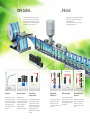
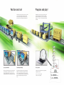
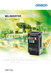
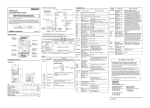
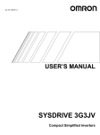
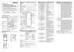
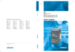
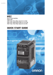
MX 2 INVERTER Born to drive machines » Omron Quality with a capital ‘Q’ » H i g h p ro g ra m m i n g f u n c t i o n a l i ty » Built-in safety Harmonised motor and machine control MOTOR C O N T RO L The MX2 is specifically designed to drive machines. It has been developed to harmonise advanced motor and machine 200% starting t orque control. Thanks to its advanced design and • Near stan d-still op eration (0 Smooth c .5 Hz) ontrol of h igh inertia • Con loads trol of fas t cyclic lo ads • M AC H I N E CO N T R OL algorithms the MX2 provides smooth control down to zero speed, plus precise operation for fast cyclic operations and torque control Torque c ontr in open lo ol op capability in open loop. The MX2 also gives you comprehensive functionality for machine • Ideal for low to m edium to applicati rque ons • Ca n replac e a flux vector o drive in r servo suitable systems • Safety ins id e Conform s to safe ty norm IS CAT3 perf O-13849 ormance level PLD • 2S afety inp uts • Exte rnal devic e monito ring (EDM ) control such as positioning, speed synchronisation and logic programming. The Special m otors MX2 is fully integrated within the Omron smart automation platform. The MX2 is the • Perman ent mag net moto • Hig rs h speed motors up to 10 00 Hz Logic program min • g • Flow ch art prog rammin g Intuitive – up to 5 tasks parallel in child of a true leader in machine automation. One par ameter auto-tu ning • Just by enterin g the k motor W ratin the MX g of the 2 gives and sa y ou smo fe opera oth tion Position ing • Integra ted in t he Omron Smart Automa tion • Up to 8 pre-set position “Homin s with g” • Sp eed syn chronis ation CX-Driv e progra mming via inte tool co grated nnecte USB po • M d rt on M odbus RS485 X2. b • O uilt-in ption u nits for E therCA Device T, Profi Net, M bus, L-II and more… Harmonised motor and machine control MOTOR C O N T RO L The MX2 is specifically designed to drive machines. It has been developed to harmonise advanced motor and machine 200% starting t orque control. Thanks to its advanced design and • Near stan d-still op eration (0 Smooth c .5 Hz) ontrol of h igh inertia • Con loads trol of fas t cyclic lo ads • M AC H I N E CO N T R OL algorithms the MX2 provides smooth control down to zero speed, plus precise operation for fast cyclic operations and torque control Torque c ontr in open lo ol op capability in open loop. The MX2 also gives you comprehensive functionality for machine • Ideal for low to m edium to applicati rque ons • Ca n replac e a flux vector o drive in r servo suitable systems • Safety ins id e Conform s to safe ty norm IS CAT3 perf O-13849 ormance level PLD • 2S afety inp uts • Exte rnal devic e monito ring (EDM ) control such as positioning, speed synchronisation and logic programming. The Special m otors MX2 is fully integrated within the Omron smart automation platform. The MX2 is the • Perman ent mag net moto • Hig rs h speed motors up to 10 00 Hz Logic program min • g • Flow ch art prog rammin g Intuitive – up to 5 tasks parallel in child of a true leader in machine automation. One par ameter auto-tu ning • Just by enterin g the k motor W ratin the MX g of the 2 gives and sa y ou smo fe opera oth tion Position ing • Integra ted in t he Omron Smart Automa tion • Up to 8 pre-set position “Homin s with g” • Sp eed syn chronis ation CX-Driv e progra mming via inte tool co grated nnecte USB po • M d rt on M odbus RS485 X2. b • O uilt-in ption u nits for E therCA Device T, Profi Net, M bus, L-II and more… 100% Control... ...0% risk! Safety is embedded in the MX2, according to ISO 13849-1, Cat 3, with two safety inputs and an External Device Monitoring (EDM) output. No external contactors on the motor side are required, meaning simpler wiring for the user. High starting torque and torque control capability in open loop mode give you full control of your machine dynamics and performance. Options for all of the major fieldbus systems and a 24 VDC external supply keeps you in full control of your machine operation. Torque Safety redundancy input Dual safety input chain 220 VAC 24 VDC Torque response Torque reference Speed EDM output EDM safety output chain Torque master Easy network integration The MX2 delivers 200% starting torque near stand-still (0.5 Hz) and can operate in torque control in open loop mode. This allows the MX2 to be used in applications where closed loop AC vector drives were previously used. Built-in RS485 Modbus communications and the possibility for integration in standard industrial networks, such as Dnet, Profibus, CANopen, CompoNet, ML-II or EtherCat makes the MX2 exceptionally easy to integrate. External 24 VDC for continuous operation With no additional hardware, a 24 VDC connection to the MX2 ensures the CPU is always in control, even if the main input is removed. This feature is vital in providing a controlled stop in emergency situations and in keeping the network communications operating. Safety embedded; ISO 13849-1, cat 3 Dual contactors at the output of the inverter are no longer required. Direct connection to a safety controller ensures compliance to ISO 13849-1, cat 3. EDM monitoring output An External Device Monitoring (EDM) output confirms the safety status of the inverter, saving you the cost and wiring of external devices to carry out the same function. Direct integration into the safety circuit MX2 inverters can fit easily into the safety circuit. The safety inputs can be linked from one inverter to another without additional safety relays. 100% Control... ...0% risk! Safety is embedded in the MX2, according to ISO 13849-1, Cat 3, with two safety inputs and an External Device Monitoring (EDM) output. No external contactors on the motor side are required, meaning simpler wiring for the user. High starting torque and torque control capability in open loop mode give you full control of your machine dynamics and performance. Options for all of the major fieldbus systems and a 24 VDC external supply keeps you in full control of your machine operation. Torque Safety redundancy input Dual safety input chain 220 VAC 24 VDC Torque response Torque reference Speed EDM output EDM safety output chain Torque master Easy network integration The MX2 delivers 200% starting torque near stand-still (0.5 Hz) and can operate in torque control in open loop mode. This allows the MX2 to be used in applications where closed loop AC vector drives were previously used. Built-in RS485 Modbus communications and the possibility for integration in standard industrial networks, such as Dnet, Profibus, CANopen, CompoNet, ML-II or EtherCat makes the MX2 exceptionally easy to integrate. External 24 VDC for continuous operation With no additional hardware, a 24 VDC connection to the MX2 ensures the CPU is always in control, even if the main input is removed. This feature is vital in providing a controlled stop in emergency situations and in keeping the network communications operating. Safety embedded; ISO 13849-1, cat 3 Dual contactors at the output of the inverter are no longer required. Direct connection to a safety controller ensures compliance to ISO 13849-1, cat 3. EDM monitoring output An External Device Monitoring (EDM) output confirms the safety status of the inverter, saving you the cost and wiring of external devices to carry out the same function. Direct integration into the safety circuit MX2 inverters can fit easily into the safety circuit. The safety inputs can be linked from one inverter to another without additional safety relays. Position and run! Program and play! The MX2 is a drive and position controller in one, ideal for modular machines where moderate positional accuracy is required. Speed synchronisation is also possible, with no additional programming required. The MX2 gives you the power to create smart solutions using PLC functionality, as standard. Via an intuitive flow chart programming tool, you can create programs with up to 1000 lines of code and with 5 tasks running in parallel. Speed synchronisation Positioning functionality Free to program With no external hardware required, and via standard parameter settings, speed synchronisation can be achieved. The MX2 will act as a speed follower to an external pulse generator/ encoder signal up to 32 KHz. Specially developed application functionality enables the MX2 to solve simple positioning tasks without the need for an external controller. Up to 8 positions, plus home, can be selected by the user, and furthermore, the MX2 can be switched between speed and position mode. • Intuitive and user friendly flow chart programming • Integrated in CX-Drive • Up to 1000 lines in a program Speed X00 • 5 tasks can run in parallel X01 Position and run! Program and play! The MX2 is a drive and position controller in one, ideal for modular machines where moderate positional accuracy is required. Speed synchronisation is also possible, with no additional programming required. The MX2 gives you the power to create smart solutions using PLC functionality, as standard. Via an intuitive flow chart programming tool, you can create programs with up to 1000 lines of code and with 5 tasks running in parallel. Speed synchronisation Positioning functionality Free to program With no external hardware required, and via standard parameter settings, speed synchronisation can be achieved. The MX2 will act as a speed follower to an external pulse generator/ encoder signal up to 32 KHz. Specially developed application functionality enables the MX2 to solve simple positioning tasks without the need for an external controller. Up to 8 positions, plus home, can be selected by the user, and furthermore, the MX2 can be switched between speed and position mode. • Intuitive and user friendly flow chart programming • Integrated in CX-Drive • Up to 1000 lines in a program Speed X00 • 5 tasks can run in parallel X01 Multi-function Compact Inverter 3G3MX2 With Machine Automation Mentality • Current vector Control. • High Starting torque: 200% at 0.5 Hz. • Double rating VT 120%/1 min and CT 150% /1 min. • Speed range up to 1,000 Hz. • Positioning functionality. • Safety embedded compliant with ISO 13849-1: 2006 (PLd) (under application) (double input circuit and external device monitor) • Modbus communications. • PC Configuration tool: CX-Drive. Interpreting Model Numbers 3G3MX2 Voltage class B 1-phase 200 VAC (200-V class) 2 4 3-phase 200 VAC (200-V class) 3-phase 400 VAC (400-V class) Max. applicable motor capacity (CT) 001 002 004 007 015 022 030 0.1 kW 0.2 kW 0.4 kW 0.75 kW 1.5 kW 2.2 kW 3.0 kW 037 040 055 075 110 150 3.7 kW 4.0 kW 5.5 kW 7.5 kW 11 kW 15 kW 1 3G3MX2 Ordering Information International Standards The standards are abbreviated as follows: U: UL, U1: UL (Class I Division 2 Products for Hazardous Locations), C: CSA, UC: cULus, UC1: cULus (Class I Division 2 Products for Hazardous Locations), CU: cUL, N: NK, L: Lloyd, and CE: EC Directives. Contact your OMRON representative for further details and applicable conditions for these standards. 3G3MX2 Inverter Models Rated voltage 3-phase 200 VAC 3-phase 400 VAC 1-phase 200 VAC Enclosure ratings IP20 IP20 IP20 Max. applicable motor capacity CT: Heavy load VT: Light load Model 0.1kW 0.2 kW 3G3MX2-A2001 0.2 kW 0.4 kW 3G3MX2-A2002 0.4 kW 0.75 kW 3G3MX2-A2004 0.75 kW 1.1 kW 3G3MX2-A2007 1.5 kW 2.2 kW 3G3MX2-A2015 2.2 kW 3.0 kW 3G3MX2-A2022 3.7 kW 5.5 kW 3G3MX2-A2037 5.5 kW 7.5 kW 3G3MX2-A2055 7.5 kW 11 kW 3G3MX2-A2075 11 kW 15 kW 3G3MX2-A2110 15 kW 18.5 kW 3G3MX2-A2150 0.4 kW 0.75 kW 3G3MX2-A4004 0.75 kW 1.5 kW 3G3MX2-A4007 1.5 kW 2.2 kW 3G3MX2-A4015 2.2 kW 3.0 kW 3G3MX2-A4022 3.0 kW 4.0 kW 3G3MX2-A4030 4.0 kW 5.5 kW 3G3MX2-A4040 5.5 kW 7.5 kW 3G3MX2-A4055 7.5 kW 11 kW 3G3MX2-A4075 11 kW 15 kW 3G3MX2-A4110 15 kW 18.5 kW 3G3MX2-A4150 0.1 kW 0.2 kW 3G3MX2-AB001 0.2 kW 0.4 kW 3G3MX2-AB002 0.4 kW 0.55 kW 3G3MX2-AB004 0.75 kW 1.1 kW 3G3MX2-AB007 1.5 kW 2.2 kW 3G3MX2-AB015 2.2 kW 3.0 kW 3G3MX2-AB022 For option, refer to 15 page. Support Software Product name FA Integrated Tool Package CX-OneVer. 4.@ Specifications The CX-One is a package that integrates the Support Software for OMRON PLCs and components. CX-One runs on the following OS. Windows 2000 (Service Pack 4 or higher), XP, Vista or 7 Note: Except for 64-bit version CX-One Ver.4.@ includes CX-Programmer Ver.9.@. For details, refer to the CX-One catalog (Cat. No. R134). The CX-One Lite is a subset of the complete CX-One package that provides only the Support Software required for micro PLC applications. FA Integrated Tool CX-One Lite runs on the following OS. Package Windows 2000 (Service Pack 4 or higher), XP, Vista or 7 CX-One Lite Ver. 4.@ Note: Except for 64-bit version CX-One Ver.4.@ includes Micro PLC Edition CX-Programmer Ver.9.@. . Number of licenses Media Model CD CXONE-AL01C-V4 DVD *2 CXONE-AL01D-V4 Standards 1 license *1 --- 1 license CD CXONE-LT01C-V4 CX-Drive can still be ordered individually in the following model numbers. Application software to set and control data for Inverters and CX-Drive Ver.1.@ Servos. 1 license CD WS02-DRVC1 OS: Windows 2000 (Service Pack 3a or higher), XP, or Vista *1. Multi licenses are available for the CX-One (3, 10, 30, or 50 licenses). *2. When purchasing the DVD format, verify the computer model and DVD drive specifications before purchasing. 2 --- 3G3MX2 Standard Specification List 3-phase 200 V Class Function name 3-phase 200 V Model name (3G3MX2-) Applicable kW motor capacity HP Rated output capacity [kVA] 200 V 240 V A2001 A2002 A2004 A2007 A2015 A2022 A2037 A2055 A2075 A2110 CT 0.1 0.2 0.4 0.75 1.5 2.2 3.7 5.5 7.5 11 15 VT 0.2 0.4 0.75 1.1 2.2 3.0 5.5 7.5 11 15 18.5 CT 1/8 1/4 1/2 1 2 3 5 7 1/2 10 15 20 VT 1/4 1/2 1 1 1/2 3 4 7 1/2 10 15 20 25 CT 0.2 0.5 1.0 1.7 2.7 3.8 6.0 8.6 11.4 16.2 20.7 23.9 VT 0.4 0.6 1.2 2.0 3.3 4.1 6.7 10.3 13.8 19.3 CT 0.3 0.6 1.2 2.0 3.3 4.5 7.2 10.3 13.7 19.5 24.9 VT 0.4 0.7 1.4 2.4 3.9 4.9 8.1 12.4 16.6 23.2 28.6 Rated input voltage 3-phase 200 V - 15% to 240 V + 10%, 50/60 ± 5% Rated output voltage Rated output current [A] 3-phase 200 to 240 V (The output cannot exceed the incoming voltage). CT 1.0 1.6 3.0 5.0 8.0 11.0 17.5 25.0 33.0 47.0 60.0 VT 1.2 1.9 3.5 6.0 9.6 12.0 19.6 30.0 40.0 56.0 69.0 50 50 50 50 50 20 20 20 20 10 10 17 10 Short-time deceleration braking torque (%) (Discharge Resistor not connected) Braking Resistor circuit * A2150 Regenerative braking Min. connectable resistance [] Weight [kg] Built-in Braking Resistor circuit (separate Discharge Resistor) 100 100 100 50 50 35 1.0 1.0 1.1 1.2 1.6 1.8 Dimensions (width height) [mm] 68 128 Dimensions (depth) [mm] * The BRD usage is 10%. 109 122.5 145.5 35 20 17 2.0 3.3 3.4 108 128 140 128 140 260 170.5 170.5 155 5.1 7.4 180 296 220 350 175 3-phase 400 V Class Function name 3-phase 400 V Model name (3G3MX2-) Applicable kW motor capacity HP Rated output capacity [kVA] 380 V 480 V A4004 A4007 A4015 A4022 A4030 A4040 A4055 A4075 A4110 CT 0.4 0.75 1.5 2.2 3.0 4.0 5.5 7.5 11 15 VT 0.75 1.5 2.2 3.0 4.0 5.5 7.5 11 15 18.5 CT 1/2 1 2 3 4 5 7 1/2 10 15 20 VT 1 2 3 4 5 7 1/2 10 15 20 25 CT 1.1 2.2 3.1 3.6 4.7 6.0 9.7 11.8 15.7 20.4 VT 1.3 2.6 3.5 4.5 5.7 7.3 11.5 15.1 20.4 25.0 CT 1.4 2.8 3.9 4.5 5.9 7.6 12.3 14.9 19.9 25.7 VT 1.7 3.4 4.4 5.7 7.3 9.2 14.5 19.1 25.7 31.5 Rated input voltage 3-phase 380 V - 15% to 480 V + 10%, 50/60 ± 5% Rated output voltage Rated output current [A] 3-phase 380 to 480 V (The output cannot exceed the incoming voltage). CT 1.8 3.4 4.8 5.5 7.2 9.2 14.8 18.0 24.0 31.0 VT 2.1 4.1 5.4 6.9 8.8 11.1 17.5 23.0 31.0 38.0 50 50 50 20 20 20 20 20 10 10 Short-time deceleration braking torque (%) (Discharge Resistor not connected) Braking Resistor circuit * A4150 Regenerative braking Min. connectable resistance [] Weight [kg] Built-in Braking Resistor circuit (separate Discharge Resistor) 180 180 180 100 100 1.5 1.6 1.8 1.9 1.9 Dimensions (width height) [mm] Dimensions (depth) [mm] * The BRD usage is 10%. 108 128 143.5 170.5 100 70 70 70 35 2.1 3.5 3.5 4.7 5.2 140 128 140 260 180 296 170.5 155 175 3 3G3MX2 1-phase 200 V Class Function name 1-phase 200 V Model name (3G3MX2-) Applicable kW motor capacity HP Rated output capacity [kVA] 200 V 240 V AB001 AB002 AB004 AB007 AB015 AB022 CT 0.1 0.2 0.4 0.75 1.5 2.2 VT 0.2 0.4 0.55 1.1 2.2 3.0 CT 1/8 1/4 1/2 1 2 3 VT 1/4 1/2 3/4 1 1/2 3 4 CT 0.2 0.5 1.0 1.7 2.7 3.8 VT 0.4 0.6 1.2 2.0 3.3 4.1 CT 0.3 0.6 1.2 2.0 3.3 4.5 VT 0.4 0.7 1.4 2.4 3.9 4.9 Rated input voltage 1-phase 200 V - 15% to 240 V + 10%, 50/60 Hz ± 5% Rated output voltage Rated output current [A] 3-phase 200 to 240 V (The output cannot exceed the incoming voltage). CT 1.0 1.6 3.0 5.0 8.0 11.0 VT 1.2 1.9 3.5 6.0 9.6 12.0 50 50 50 50 50 20 Short-time deceleration braking torque (%) (Discharge Resistor not connected) Braking Resistor circuit * Regenerative braking Min. connectable resistance [] Weight [kg] Built-in Braking Resistor circuit (separate Discharge Resistor) 100 100 100 50 50 35 1.0 1.0 1.1 1.6 1.8 1.8 Dimensions (width height) [mm] Dimensions (depth) [mm] * The BRD usage is 10%. 4 68 128 109 108 128 122.5 170.5 3G3MX2 Common Specifications Function name Control Enclosure ratings *1 Specifications Open type (IP20) Control method Phase-to-phase sinusoidal modulation PWM Output frequency range *2 0.10 to 400 Hz (or 1,000 Hz in the high-frequency mode; restrictions apply) Frequency precision *3 Digital command: 0.01% of the max. frequency, Analog command: 0.2% of the max. frequency (25C10C) Frequency setting resolution Digital setting: 0.01 Hz, Analog setting: One-thousandth of the maximum frequency Voltage/Frequency characteristics V/f characteristics (constant/reduced torque) Sensorless vector control, V/f control with speed feedback Overload current rating Heavy load rating (CT): 150%/60 s Light load rating (VT): 120%/60 s Instantaneous overcurrent protection 200% of the value of heavy load rating (CT) Acceleration/Deceleration time 0.01 to 3600 s (linear/curve selection), acceleration/deceleration 2 setting available Carrier frequency adjustment range 2 to 15 kHz (with derating) Starting torque 200%/0.5 Hz (sensorless vector control) External DC injection braking Starts at a frequency lower than that in deceleration via the STOP command, at a value set lower than that during operation, or via an external input. (Level and time settable). Communications Output signal Input signal Protective functions Frequency settings Digital Operator External analog input signal: Variable resistance/0 to 10 VDC/4 to 20 mA, Modbus communication (Modbus-RTU) RUN/STOP command Digital Operator External digital input signal (3-wire input supported), Modbus communication (Modbus-RTU) Multi-function input 7 points (Selectable from 59 functions) Analog input 2 points (Voltage FV terminal: 10 bits/0 to 10 V, Current FI terminal: 10 bits/4 to 20 mA) Pulse input 1 point (RP terminal: 32 kHz max., 5 to 24 VDC) Multi-function output 2 points (P1/EDM, P2; selectable from 43 functions) Relay output 1 point (1c contact: MC, MA, MB; selectable from 43 functions) Analog output (Frequency monitor) 1 point (AM terminal: Voltage 10 bits/0 to 10 V) (Frequency, current selectable) Pulse output 1 point (MP terminal: 32 kHz max., 0 to 10 V) RS-422 RJ45 connector (for Digital Operator) RS-485 Control circuit terminal block, Modbus communication (Modbus-RTU) USB USB1.1, mini-B connector Other functions General specifications Overcurrent, overvoltage, undervoltage, electronic thermal, temperature error, ground fault overcurrent at power-on status, rush current prevention circuit, overload limit, incoming overvoltage, external trip, memory error, CPU error, USP error, communication error, overvoltage suppression during deceleration, protection upon momentary power outage, emergency cutoff, etc. AVR function, V/f characteristics switching, upper/lower limit, 16-step speeds, starting frequency adjustment, jogging operation, carrier frequency adjustment, PID control, frequency jump, analog gain/ bias adjustment, S shape acceleration/deceleration, electronic thermal characteristics, level adjustment, restart function, torque boost function, fault monitor, soft lock function, frequency conversion display, USP function, motor 2 control function, UP/DWN, overcurrent suppression function, etc. Ambient temperature -10 to 50C (However, derating is required). Ambient storage temperature -20C to 65C (short-time temperature during transport) Humidity 20% to 90% RH (with no condensation) Vibration 5.9 m/s2 (0.6G), 10 to 55 Hz Location At a maximum altitude of 1,000 m; indoors (without corrosive gases or dust) DC reactor, AC reactor, radio noise filter, input noise filter, output noise filter, regenerative braking unit, Braking Resistor, EMC noise filter, etc. Note: 1. The applicable motor is a 3-phase standard motor. For using any other type, be sure that the rated current does not exceed that of the Inverter. 2. Output voltage decreases according to the level of the power supply voltage. 3. The braking torque at the time of capacitor feedback is an average deceleration torque at the shortest deceleration (when it stops from 50 Hz). It is not a continuous regeneration torque. Also, the average deceleration torque varies depending on the motor loss. The value is reduced in operation over 50 Hz. *1. Protection method complies with JEM 1030. *2. To operate the motor at over 50/60 Hz, contact the motor manufacturer to find out the maximum allowable speed of revolution. *3. For the stable control of the motor, the output frequency may exceed the maximum frequency set in A004 (A204) by 2 Hz max. Options 5 3G3MX2 Terminal Block Specifications Names of Parts Inside the Terminal Block Cover Modbus-RTU Termination resistor selector switch OFF (Factory default) ON Safety function selector switch Disable (Factory default) Enable USB connector (mini-B) Connector for optional board Connector for Digital Operator (RJ45) EDM function selector switch Multi-function contact terminal block P1 terminal (Factory default) EDM output Control circuit terminal block A Control circuit terminal block B CHARGE indicator Main circuit terminal block 6 Name Description Modbus-RTU Termination resistor selector switch Use this Terminal Resistor selector switch for RS-485 terminals on the control circuit terminal block. When this switch is turned ON, the internal 200 Resistor is connected. Safety function selector switch Turn this switch ON when using the safety function. Turn OFF the power before turning this switch ON/OFF. For details, refer to User’s Manual (I570). EDM function selector switch Turn this switch ON when using the EDM output of the safety function. Turn OFF the power before turning this switch ON/ OFF.For details, refer to User’s Manual (I570). USB connector Use this mini-B USB connector to connect a PC. Even when the Inverter is being operated by a PC, etc., via USB connection, it can still be operated using the Digital Operator. Connector for Digital Operator Use this connector to connect the Digital Operator. Connector for optional board Use this connector to mount the optional board. (The optional board will be released soon.) Control circuit terminal blocks A and B These terminal blocks are used to connect various digital/analog input and output signals for inverter control, etc. Multi-function contact terminal block Use this SPDT contact terminal block for relay outputs. Main circuit terminal block Use this terminal block to connect an output to the motor and Braking Resistor, etc. Also, use this terminal block to connect the inverter to the main power supply. CHARGE indicator (Charge indicator LED) This LED indicator is lit if the DC voltage of the main circuit (between terminals P/+2 and N/-) remains approx. 45 V or above after the power has been cut off. Before wiring, etc. confirm that the Charge LED indicator is turned OFF. 3G3MX2 Main Circuit Terminals Specifications [Main Circuit Terminal Block] 3G3MX2-A2001 to A2037 3G3MX2-A4004 to A4040 3G3MX2-AB001 to AB022 From power supply [Main Circuit Terminal Block] 3G3MX2-A2001 to A2037 3G3MX2-A4004 to A4040 3G3MX2-AB001 to AB022 To motors (Connect to L1 and N for 1-phase) Terminal symbol From power supply To motors Terminal name Description Main power supply input terminal Connect the input AC power supply.In the case of a 1-phase 200 V power supply, connect to L1 and N. Inverter output terminal Connect a 3-phase motor. DC reactor connection terminal Remove the shorting bar between terminals +1 and P/+2, and connect the optional DC reactor. Braking Resistor connection terminal Connect optional braking resistors. (If a braking torque is required) Regenerative braking unit connection terminal Connect optional regenerative braking units. (When braking torque is required or the built-in braking circuit is not sufficient) Ground terminal This is a ground terminal. Connect this terminal to the ground. Provide Class D grounding for 200 V class models, and class C grounding for 400 V class models. On 200 V class models of 3.7 kW or below and 400 V class models of 4.0 kW or below, the ground terminal is located on the cooling fin. R/L1 S/L2 T/L3 U/T1 V/T2 W/T3 +1 P/+2 P/+2 RB P/+2 N/ G 7 3G3MX2 Control Circuit Terminals Specifications Communication RS-485 Logic common and power supply Logic input Shorting bar Relay output Communication Pulse Pulse Analog input and output input power supply RS-485 Terminal symbol Analog Power supply Logic output Description Specifications SC Input signal common This is a common terminal used by the internal power supply, digital input and analog input/ output terminals. FS Frequency reference power supply 10 VDC power supply for the FV terminal. Allowable max. current: 7 mA FV Frequency reference input terminal (analog voltage input) Use this terminal if the frequency reference is provided by 0 to 10 VDC voltage input. Input impedance Approx. 10 k Allowable input voltage range 0.3 to +12 VDC FI Frequency reference terminal (analog current input) Use this terminal if the frequency reference is provided by 4 to 20 mA current input. Input impedance 100 Allowable input range 0 to 24 mA Frequency setting input Sensor input S5/TH External thermistor input (also used as multi-function input terminal) Connect an external thermistor between the SCs, to trip the Inverter when a temperature error occurs. (The inverter will trip when the input from thermistor is approx. 3 k or higher.) Since this PTC type input is also used as the multi-function input terminal, setting of C005 is required. For details, refer to User’s Manual (I570). Output AM Multi-function analog output (voltage) Specified signals can be output using voltage signals of 0 to 10 VDC. SC Input signal common This is a common terminal used by the internal power supply, digital input and analog input/ output terminals. P24 24 VDC power supply for contact input Power supply terminal signal.This is used as a common terminal if the for input signal source logic is input. PSC Sink logic input: Shorted with P24 Source logic input: Shorted with SC Power supply terminal To drive the contact input using an external power for input terminal supply, remove the shorting bar. For details, refer to User’s Manual (I570). S7/EB S6 S5/TH S4/GS2 S3/GS1 S2 S1 Multi-function input terminal S4/GS2 S3/GS1 Safety input Contact Input Digital Power supply 8 Terminal name Analog output AM Allowable max. current: 100 mA Select 7 functions from among 59, and allocate them to terminals S1 through S7/EB. Both sink Voltage between each input and PSC and source logics are supported. For details, refer ON voltage: 18 V min. to User’s Manual (I570). OFF voltage: 3 V max. Allowable max. voltage: 27 VDC Load current: 5 mA (at 24 V) Enabled when the safety function selector switch is turned ON. For details, refer to User’s Manual (I570). 3G3MX2 Terminal symbol Terminal name Description Specifications Input pulse 32 kHz max. Pulse input-A A pulse input for frequency setting. (Take note that the internal circuit is different from input terminals S7/EB.) S7/EB Pulse input-B A pulse input for frequency setting. (Take note that the internal circuit is different from input terminal RP.) P1/EDM P2 Multi-function output terminal Select 2 functions from among 43, and allocate them to terminals P1 through P2. Both sink and source logics are supported. For details, refer to User’s Manual (I570). P1/EDM Safety monitor Enabled when the EDM function selector switch is ON. For details, refer to "Safety Function" on page 5-167. MA MB Relay output terminal Pulse Relay Pulse Output Digital Open collector Input RP Voltage between input and SC ON voltage: 4 V min. OFF voltage: 1 V max. Allowable max. voltage: 27 VDC Input pulse 1.8 kHz max. MC MP Serial RS+ communication RS ON voltage: 18 V min. OFF voltage: 3 V max. Allowable max. voltage: 27 VDC Load current: 5 mA (at 24 V) Open collector output Between each terminal and PC Allowable max. voltage: 27 V Allowable max. current: 50 mA Voltage drop when ON: 4 V max. Select the desired functions from among 43 functions, and allocate them to these terminals. SPDT contact. The factory default of Relay Output (MA, MB) Relay output common Contact Selection (C036) is NC contact between MA-MC, and NO contact between MB-MC. Max. contact capacity MA-MC: 250 VAC, 2 A (resistance) 0.2 A (induction) MB-MC: 250 VAC, 1 A (resistance) 0.2 A (induction) Contact min. capacity 100 VAC, 10mA 5 VDC, 100mA Pulse output Output pulse: 32 kHz max. Output voltage: 10 VDC Allowable max. current: 2 mA Pulses are output. RS-485 port Modbus port (RS-485) RS+ RS-485 differential (+) signal RS- RS-485 differential () signal Max. speed: 115.2 kbps Built-in Terminal Resistor: 200 Slide switch selection Switching Method for Input Control Logics Multi-function input terminals are set to sink logic at the factory. To switch the input control logic to source logic, remove the shorting bar between terminals P24 and PSC on the control circuit terminal block, and connect it between terminals PSC and SC. (2) Source logic (1) Sink logic Shorting bar Shorting bar 9 3G3MX2 Connection Diagram ELB Single-phase 3-phase power supply MC R/L1 S/L2 T/L3 U/T1 If any external source-logic output equipment or power supply is used, refer to "Connection to Programmable Controllers (PLC)" on page 2-22. Shorting bar M V/T2 24VDC W/T3 P24 Motor Shorting bar PSC +1 DC reactor To connect the DC reactor, remove the shorting bar. SC P/+2 RB N/− S7/EB Braking Resistor * S6 Multi-function input (7 contact points) MC S5/TH S4/GS2 MA S3/GS1 MB Multi-function relay output S2 S1 2 kΩ or more 10 VDC power supply (7 mA Max.) Analog voltage input 0 to 10 V (10 bits) Analog current input 4 to 20 mA (10 bits) Pulse input 5 to 24 VDC (32 kHz Max.) Analog voltage output 0 to 10 V (10 bits) Pulse output 0 to 10 VDC (32 kHz Max.) FS P2 P1/EDM Multi-function output (2 terminals) FV PC FI RS+ Serial communication port (RS-485/Modbus-RTU) RP RS− AM When using a Regenerative Braking Unit MP P/+2 Regenerative Braking Resistor * Braking Unit * RB SC N/− Class D (200 V class) Class C (400 V class) P P N RB * Option Note: 1. Connect a single-phase 200 V AC input to terminals L1 and N. 2. Factory default settings for relay output are NC contact for MA and NO contact for MB. 10 3G3MX2 Names of Parts and their Descriptions Data display RUN Command enabled LED indicator 8.8.8.8. USB connector Operation key Name 8.8.8.8. RJ45 connector Description POWER LED Lit (green) while the Inverter is receiving power. ALARM LED Lit (red) when the Inverter trips. For information on how to reset the trip, refer to User’s Manual (I570). PROGRAM LED indicator Lit (green) when the displayed data (set value) can be changed. Blinks if the set value is invalid. Refer to User’s Manual (I570). RUN (during RUN) LED indicator Lit (green) when the Inverter is running. (Lit when there is either a "valid RUN command" or "inverter output." Accordingly, it is also lit when a RUN command is issued at a set frequency of 0 Hz or while the motor is decelerating after the RUN command is turned OFF.) Monitor LED indicator (Hz) Lit (green) when the displayed data is frequency. Monitor LED indicator (A) Lit (green) when the displayed data is current. RUN Command enabled LED indicator Lit (green) when the RUN command is set to the Digital Operator. (The RUN key on the Digital Operator is enabled.) Display Various parameters, frequency/set value and other data are displayed (red). RUN key Runs the Inverter. Take note that this key is enabled only when the RUN command destination is the Digital Operator. STOP/RESET key This key decelerates the Inverter to a stop. (Although the STOP/RESET key is enabled even when a RUN command is issued to a destination other than the Digital Operator (factory default), it can be disabled by a Setting (b087).) If the Inverter is already tripped, the trip will be reset (return from the tripping). Mode key Parameter is displayed: Move to the beginning of the next function group. Data is displayed: Cancel the setting and return to the parameter display. Individual input mode: Move the blinking digit to the left. Regardless of the displayed screen, pressing and holding this key (for 1 second or more) displays the data for Output Frequency Monitor (d001). Increment key Decrement key These keys are used to increment/decrement a parameter or set data. Pressing and holding each key increases the incrementing/decrementing speed. Pressing the Increment and Decrement keys together activates the "Individual Input MODE" where each digit can be edited independently. Enter key Parameter is displayed: Move to the data display. Data is displayed: Confirm/store the setting (in the EEPROM) and return to the parameter display. Individual input mode: Move the blinking digit to the right. USB connector Use this connector (mini-B type) to connect a PC. The Inverter can still be operated from the Digital Operator even when it is being operated using a PC, etc., via USB communication. RJ45 connector Use this connector (RS-422) to connect the optional Remote Operator. Once the Remote Operator is connected, the keys on the main unit become disabled. In this case, use b150 to set the item to be displayed. 11 3G3MX2 Dimensions 3G3MX2-AB001 3G3MX2-AB002 3G3MX2-AB004 3G3MX2-A2001 3G3MX2-A2002 3G3MX2-A2004 3G3MX2-A2007 (Unit: mm) 68 56 4.5 dia. 128 118 8.8.8.8. 5 Power supply D 1-phase 200 V W [mm] H [mm] 3G3MX2-AB001 3G3MX2-AB002 D [mm] D1 [mm] 109 13.5 122.5 27 109 13.5 3G3MX2-A2004 122.5 27 3G3MX2-A2007 145.5 50 3G3MX2-AB004 3G3MX2-A2001 3G3MX2-A2002 68 128 2.6 D1 3-phase 200 V Model 108 Two, 4.5 dia. 96 128 8.8.8.8. 118 3G3MX2-AB007 3G3MX2-AB015 3G3MX2-AB022 3G3MX2-A2015 3G3MX2-A2022 3G3MX2-A4004 3G3MX2-A4007 3G3MX2-A4015 3G3MX2-A4022 3G3MX2-A4030 5 Power supply Model 3-phase 200 V 3G3MX2-A2015 3G3MX2-A2022 D 1-phase 200 V 3G3MX2-AB007 3G3MX2-AB015 3G3MX2-AB022 4.4 D1 3G3MX2-A4004 12 3-phase 400 V 3G3MX2-A4007 3G3MX2-A4015 3G3MX2-A4022 3G3MX2-A4030 W [mm] 108 H [mm] 128 D [mm] D1 [mm] 170.5 55 143.5 28 170.5 55 3G3MX2 3G3MX2-A2037 3G3MX2-A4040 140 Two, 4.5 dia. 128 128 118 8.8.8.8. 170.5 5 Model 3G3MX2-A2037 3-phase 400 V 3G3MX2-A4040 W [mm] H [mm] D [mm] D1 [mm] 140 128 170.5 W [mm] H [mm] D [mm] D1 [mm] 140 260 155 55 4.4 55 Power supply 3-phase 200 V 140 Two, 6 dia. 122 260 248 8.8.8.8. 73.3 155 6 Power supply Model 3-phase 200 V 3G3MX2-A2055 3G3MX2-A2075 3-phase 400 V 3G3MX2-A4055 3G3MX2-A4075 73.3 6 3G3MX2-A2055 3G3MX2-A2075 3G3MX2-A4055 3G3MX2-A4075 13 3G3MX2 3G3MX2-A2110 3G3MX2-A4110 3G3MX2-A4150 180 Two, 7 dia. 160 296 284 8.8.8.8. Power supply Model W [mm] H [mm] D [mm] D1 [mm] 180 296 175 97 Model W [mm] H [mm] D [mm] D1 [mm] 3G3MX2-A2150 220 350 175 84 3-phase 200 V 3G3MX2-A2110 3-phase 400 V 3G3MX2-A4110 3G3MX2-A4150 Power supply 3-phase 200 V 5 97 175 7 3G3MX2-A2150 220 Two, 7 dia. 192 350 336 8.8.8.8. 5 84 175 7 14 SYSDRIVE Option 3G3MX2 Related Options Specifications Type % ED Voltage 200V (Single-/ Threephase) 3% 10 sec max. BRAKING RESISTORS 400V (Threephase) 200V (Single-/ Threephase) 10% 10 sec max. 400V (Threephase) Max. Motor kW Inverter 3G3MX2-A@ 3-Phase 1-Phase Connectable min. resistance Resist Braking torque % 200 Model 0.12 2001 B001 0.25 2002 B002 0.55 2004 B004 1.1 2007 B007 1.5 2015 B015 2.2 2022 B022 4.0 2037 - 5.5 2055 - 7.5 2075 - 11 2110 - 15 2150 - 0.55 4004 - 1.1 4007 - 1.5 4015 - 200 190 AX-REM00K1200-IE 2.2 4022 - 200 130 AX-REM00K2200-IE 3.0 4030 - 4.0 4040 - 5.5 4055 - 7.5 4075 - 11 4110 - 15 4150 - 0.12 2001 B001 0.25 2002 B002 0.55 2004 B004 100 400 200 50 70 35 20 17 10 180 100 70 30 100 75 35 180 180 100 140 90 50 75 55 AX-REM00K1400-IE AX-REM00K1200-IE AX-REM00K2070-IE AX-REM00K4075-IE AX-REM00K4035-IE 35 40 AX-REM00K6035-IE 17 55 AX-REM00K9017-IE 400 120 75 200 200 160 120 140 100 AX-REM00K1400-IE AX-REM00K2120-IE AX-REM00K4075-IE 100 50 AX-REM00K6100-IE 70 55 AX-REM00K9070-IE 400 200 200 180 AX-REM00K1400-IE 180 AX-REM00K1200-IE 1.1 2007 B007 1.5 2015 B015 2.2 2022 B022 4.0 2037 - 5.5 2055 - 7.5 2075 - 11 2110 - 15 2150 - 0.55 4004 - 1.1 4007 - 1.5 4015 - 2.2 4022 - 3.0 4030 - 4.0 4040 - 100 140 AX-REM00K6100-IE 5.5 4055 - 70 150 AX-REM00K9070-IE 7.5 4075 - 70 70 110 AX-REM01K9070-IE 11 4110 - 70 75 AX-REM02K1070-IE 15 4150 - 30 35 110 AX-REM03K5035-IE 50 35 20 17 10 180 70 200 AX-REM00K2070-IE 75 130 AX-REM00K4075-IE 35 180 AX-REM00K4035-IE 35 100 AX-REM00K6035-IE 20 150 AX-REM00K9020-IE 17 110 AX-REM01K9017-IE 17 75 AX-REM02K1017-IE 10 95 AX-REM03K5010-IE 400 200 100 120 200 200 190 200 160 AX-REM00K1400-IE AX-REM00K2200-IE AX-REM00K5120-IE 15 3G3MX2 Specifications Type Type 200V (Single-phase) EMC LINE FILTERS Foot Mounting [Rasmi] 200V (Three-phase) 400V (Three-phase) 200V (Single-phase) Separate Mounting [Schaffner] Inverter 3G3MX2-A@ Voltage 200V (Three-phase) 400V (Three-phase) Rated Current (A) Model B001 / B002 / B004 10 AX-FIM1010-RE B007 14 AX-FIM1014-RE B015 / B022 24 AX-FIM1024-RE 2001 / 2002 / 2004 / 2007 10 AX-FIM2010-RE 2015 / 2022 20 AX-FIM2020-RE 2037 30 AX-FIM2030-RE 2055 / 2075 60 AX-FIM2060-RE 2110 80 AX-FIM2080-RE 2150 100 AX-FIM2100-RE 4004 / 4007 5 AX-FIM3005-RE 4015 / 4022 / 4030 10 AX-FIM3010-RE 4040 14 AX-FIM3014-RE 4055 / 4075 23 AX-FIM3030-RE 4110 / 4150 50 AX-FIM3050-RE B001 / B002 / B004 10 AX-FIM1010-SE B007 / B015 / B022 24 AX-FIM1024-SE 2001 / 2002 / 2004 / 2007 10 AX-FIM2010-SE 2015 / 2022 20 AX-FIM2020-SE 2037 30 AX-FIM2030-SE 2055 / 2075 60 AX-FIM2060-SE 2110 80 AX-FIM2080-SE 2150 100 AX-FIM2100-SE 4004 / 4007 5 AX-FIM3005-SE 4015 / 4022 / 4030 10 AX-FIM3010-SE 4040 14 AX-FIM3014-SE 4055 / 4075 23 AX-FIM3030-SE 4110 / 4150 50 AX-FIM3050-SE Specifications INPUT AC REACTORS Type 16 Inverter 3G3MX2-A@ Voltage 200V (Single-phase) 200V (Three-phase) 400V (Three-phase) B001 / B002 / B004 / B007 / B015 / B022 Model UNDER DEVELOPMENT 2001 / 2002 / 2004 / 2007 AX-RAI02800080-DE 2015 / 2022 / 2037 AX-RAI00880200-DE 2055 / 2075 AX-RAI00350335-DE 2110 / 2015 AX-RAI00180670-DE 4004 / 4007 / 4015 AX-RAI07700050-DE 4022 / 4030 / 4040 AX-RAI03500100-DE 4055 / 4075 AX-RAI01300170-DE 4110 / 4150 AX-RAI00740335-DE 3G3MX2 Specifications Type 200V (Single-phase) DC REACTORS Inverter 3G3MX2-A@ Voltage 200V (Three-phase) 400V (Three-phase) B001 / B002 AX-RC10700032-DE B004 AX-RC06750061-DE B007 AX-RC03510093-DE B015 AX-RC02510138-DE B022 AX-RC01600223-DE 2001 / 2002 AX-RC21400016-DE 2004 AX-RC10700032-DE 2007 AX-RC06750061-DE 2015 AX-RC03510093-DE 2022 AX-RC02510138-DE 2037 AX-RC01600223-DE 2055 AX-RC01110309-DE 2075 AX-RC00840437-DE 2110 AX-RC00590614-DE 2150 AX-RC00440859-DE 4004 AX-RC43000020-DE 4007 AX-RC27000030-DE 4015 AX-RC14000047-DE 4022 AX-RC10100069-DE 4030 AX-RC08250093-DE 4040 AX-RC06400116-DE 4055 AX-RC04410167-DE 4075 AX-RC03350219-DE 4110 AX-RC02330307-DE 4150 OUTPUT AC REACTORS 200V (Single-phase) 200V (Three-phase) 400V (Three-phase) Model AX-RC01750430-DE B001 / B002 / B004 AX-RAO11500026-DE B007 AX-RAO07600042-DE B015 AX-RAO04100075-DE B022 AX-RAO03000105-DE 2001 / 2002 / 2004 AX-RAO11500026-DE 2007 AX-RAO07600042-DE 2015 AX-RAO04100075-DE 2022 AX-RAO03000105-DE 2037 AX-RAO01830160-DE 2055 AX-RAO01150220-DE 2075 AX-RAO00950320-DE 2110 AX-RAO00630430-DE 2150 AX-RAO00490640-DE 4004 / 4007 / 4015 AX-RAO16300038-DE 4022 AX-RAO11800053-DE 4030 / 4040 AX-RAO07300080-DE 4055 AX-RAO04600110-DE 4075 AX-RAO03600160-DE 4110 AX-RAO02500220-DE 4150 AX-RAO02000320-DE 17 3G3MX2 Specifications RADIO NOISE FILTERS Type Description 21 AX-FER2102-RE For 15 kW motors or below 25 AX-FER2515-RE For 45 kW motors or below 55 AX-FER5045-RE Description Model Profibus option card 3G3AX-MX2-PRT-E DeviceNet option card 3G3AX-MX2-PRT-E EtherCat option card 3G3AX-MX2-ERT* CompoNet option card 3G3AX-MX2-CRT* Mechatrolink II option card 3G3AX-MX2-ML2* CanOpen option card 3G3AX-MX2-CORT* PC Communication cable (2m, PC USB to Mini USB Connecting Cable with Ferrite) AX-CUSBM002-E Remote operator with frequency reference volume 3G3AX-OP01 LCD Remote operator (5 Line LCD remote operator with copy function, cable length max. 3m.) 3 meters cable for connecting remote operator Related Manuals Manual No. Model AX-OP05-E 3G3AX-CAJOP300-EE * Available soon. Please contact OMRON for availability. 18 Model For 2.2 kW motors or below Type REMOTE PC COMMUNICATON OPERATOR CABLE OPTION Diameter Category I570 3G3MX2 USERS MANUAL W453 CXONE-ALL@@C/D-V@ WS02-DRVC01 OPERATION MANUAL Read and Understand this Catalog Please read and understand this catalog before purchasing the product. Please consult your OMRON representative if you have any questions or comments. Warranty and Limitations of Liability WARRANTY OMRON's exclusive warranty is that the products are free from defects in materials and workmanship for a period of one year (or other period if specified) from date of sale by OMRON. OMRON MAKES NO WARRANTY OR REPRESENTATION, EXPRESS OR IMPLIED, REGARDING NON-INFRINGEMENT, MERCHANTABILITY, OR FITNESS FOR PARTICULAR PURPOSE OF THE PRODUCTS. ANY BUYER OR USER ACKNOWLEDGES THAT THE BUYER OR USER ALONE HAS DETERMINED THAT THE PRODUCTS WILL SUITABLY MEET THE REQUIREMENTS OF THEIR INTENDED USE. OMRON DISCLAIMS ALL OTHER WARRANTIES, EXPRESS OR IMPLIED. LIMITATIONS OF LIABILITY OMRON SHALL NOT BE RESPONSIBLE FOR SPECIAL, INDIRECT, OR CONSEQUENTIAL DAMAGES, LOSS OF PROFITS, OR COMMERCIAL LOSS IN ANY WAY CONNECTED WITH THE PRODUCTS, WHETHER SUCH CLAIM IS BASED ON CONTRACT, WARRANTY, NEGLIGENCE, OR STRICT LIABILITY. In no event shall the responsibility of OMRON for any act exceed the individual price of the product on which liability is asserted. IN NO EVENT SHALL OMRON BE RESPONSIBLE FOR WARRANTY, REPAIR, OR OTHER CLAIMS REGARDING THE PRODUCTS UNLESS OMRON'S ANALYSIS CONFIRMS THAT THE PRODUCTS WERE PROPERLY HANDLED, STORED, INSTALLED, AND MAINTAINED AND NOT SUBJECT TO CONTAMINATION, ABUSE, MISUSE, OR INAPPROPRIATE MODIFICATION OR REPAIR. Application Considerations SUITABILITY FOR USE OMRON shall not be responsible for conformity with any standards, codes, or regulations that apply to the combination of products in the customer's application or use of the products. Take all necessary steps to determine the suitability of the product for the systems, machines, and equipment with which it will be used. Know and observe all prohibitions of use applicable to this product. NEVER USE THE PRODUCTS FOR AN APPLICATION INVOLVING SERIOUS RISK TO LIFE OR PROPERTY WITHOUT ENSURING THAT THE SYSTEM AS A WHOLE HAS BEEN DESIGNED TO ADDRESS THE RISKS, AND THAT THE OMRON PRODUCTS ARE PROPERLY RATED AND INSTALLED FOR THE INTENDED USE WITHIN THE OVERALL EQUIPMENT OR SYSTEM. PROGRAMMABLE PRODUCTS OMRON shall not be responsible for the user’s programming of a programmable product, or any consequence thereof. Disclaimers CHANGE IN SPECIFICATIONS Product specifications and accessories may be changed at any time based on improvements and other reasons. It is our practice to change model numbers when published ratings or features are changed, or when significant construction changes are made. However, some specifications of the products may be changed without any notice. When in doubt, special model numbers may be assigned to fix or establish key specifications for your application on your request. Please consult with your OMRON representative at any time to confirm actual specifications of purchased products. DIMENSIONS AND WEIGHTS Dimensions and weights are nominal and are not to be used for manufacturing purposes, even when tolerances are shown. PERFORMANCE DATA Performance data given in this catalog is provided as a guide for the user in determining suitability and does not constitute a warranty. It may represent the result of OMRON’s test conditions, and the users must correlate it to actual application requirements. Actual performance is subject to the OMRON Warranty and Limitations of Liability. Singapore Office: OMRON ELECTRONICS PTE. LTD. 438A Alexandra Road, #05-05/08 (Lobby 2) Alexandra Technopark Singapore 119967 Tel: (65) 6547 6789 Fax: (65) 6547 6769 E-mail: [email protected] Malaysia Office: OMRON ELECTRONICS SDN. BHD. 1101 Level 11 Uptown 1 1 Jalan SS21/58 Damansara Uptown 47400 Petaling Jaya, Selangor Malaysia Tel: (60-3) 7688 2888 Fax: (60-3) 7688 2833 E-mail: [email protected] Thailand Office: OMRON ELECTRONICS CO. LTD. Rasa Tower 20th Floor 555 Phaholyothin Road Chatuchak, Bangkok 10900, Thailand Tel: (66-2) 937 0500 Fax: (66-2) 937 0501 CRM Call Centre: (66-2) 942 6700 E-mail: [email protected] Indonesia Office: PT. OMRON ELECTRONICS Graha Pratama Building, 3A Floor Jl. M.T. Haryono Kav 15 Jakarta Selatan 12810 Indonesia Tel: (62-21) 8370 9555 Fax: (62-21) 8370 9550 E-mail: [email protected] Philippines Office: OMRON ASIA PACIFIC PTE. LTD. MANILA REPRESENTATIVE OFFICE 2nd Floor, Kings Court II Building 2129 Do Chino Roces Avenue Corner Dela Rosa Street 1231 Makati City, Metro Manila Philippines Tel: (63-2) 811 2831 Fax: (63-2) 811 2583 E-mail: [email protected] Australia Offices: Sydney Office: OMRON ELECTRONICS PTY. LTD. Omron House 71 Epping Road, North Ryde Sydney, New South Wales 2113 Australia Tel: (61-2) 9878 6377 Fax: (61-2) 9878 6981 Toll Free: 1800 678838 E-mail: [email protected] Melbourne Office: OMRON ELECTRONICS PTY. LTD. Axxess Corporate Park Unit 98, 45 Gilby Road Mt Waverley Victoria 3149 Australia Tel: (61-3) 8588 2600 Fax: (61-3) 8588 2690 E-mail: [email protected] Brisbane Office: OMRON ELECTRONICS PTY. LTD. Unit 14, 1378 Lytton Road Hemmant 4174, Queensland Australia Tel: (61-7) 3859 3900 Fax: (61-7) 3348 8701 E-mail: [email protected] Adelaide Office: OMRON ELECTRONICS PTY. LTD. Suite 12, 18 Humpheries Terrace Kilkenny, SA 5009 Australia Tel: (61-8) 8440 6412 Fax: (61-8) 8345 1204 E-mail: [email protected] New Zealand Office: OMRON ELECTRONICS LTD. 65 Boston Road, Mt Eden Private Bag 92620 Symonds Street, Auckland New Zealand Tel: (64-9) 358 4400 Fax: (64-9) 358 4411 E-mail: [email protected] Asia Pacific Head Office: OMRON ASIA PACIFIC PTE. LTD. 438A Alexandra Road #05-05/08 (Lobby 2) Alexandra Technopark Singapore 119967 Tel: (65) 6835 3011 Fax: (65) 6835 2711 E-mail: [email protected] Website: eb www.omron-ap.com .omr n Cat. No. I916-E4-01 India Offices: Bangalore Office: OMRON AUTOMATION PVT. LTD. No. 43, G.N. Complex St.Johns Road Bangalore - 560 042 India Tel: (91-80) 4072 6400/401 Fax: (91-80) 4146 6403 E-mail: [email protected] Noida Office: OMRON AUTOMATION PVT. LTD. 212 & 213, 2nd Floor International Home Deco Park (IHDP) Plot No.7, Sector 127, Taj Express Way Noida 201301 India Tel: (91-120) 4745 800 Fax:(91-120) 4745 801 E-mail: [email protected] Mumbai Office: OMRON AUTOMATION PVT. LTD. 102 & 103, Meadows, Sahar Plaza, Andheri-Kurla Road, Andheri East Mumbai - 400 059 India Tel: (91-22) 4275 5600 Fax: (91-22) 4275 5602 E-mail: [email protected] Vietnam Offices: OMRON ASIA PACIFIC PTE. LTD. HANOI REPRESENTATIVE OFFICE 6th Floor, 92 Hoang Ngan Street Trung Hoa, Cau Giay Hanoi, SR Vietnam Tel: (84-4) 3556 3444 Fax: (84-4) 3556 3443 E-mail: [email protected] HO CHI MINH REPRESENTATIVE OFFICE 2nd Floor, IWA, 102 A-B, Cong Quynh, P. Pham Ngu Lao, Q1, TP. Ho Chi Minh SR Vietnam Tel: (84-8) 3920 4338 Fax: (84-8) 3920 4335 E-mail: [email protected] Authorized Distributor i