1
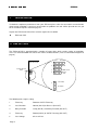
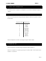
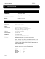
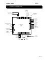
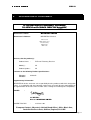
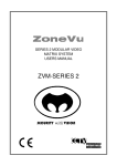
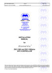
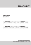
TELEMETRY RECEIVER USERS MANUAL ZVR-210 SECURITY with VISION LIMITED ISSUE 02 CONTENTS 1. ZVR-210 WELCOME 3 2. FEATURES 3 3. INSTALLATION 4 3.1 LINK SETTINGS 4 3.2 CONNECTING THE ZVR-210 5 3.3 CAMERA NUMBER ASSIGNMENT 5 4. SELF TEST DIAGNOSTICS 7 4.1 INDIVIDUAL FUNCTION TESTING 7 4.2 SEQUENTIAL TEST 7 5. SPECIFICATIONS 8 5.1 ELECTRICAL 8 5.2 PHYSICAL 8 6. CONNECTION DIAGRAM 9 7. TROUBLE SHOOTING GUIDE 10 8. DECLARATION OF CONFORMITY 11 9. SUPPORT 12 10. PRODUCT WARRANTY 13 11. 14 DOCUMENT HISTORY Page 2 1. ISSUE 02 ZVR-210 WELCOME Thank you for purchasing the ZoneVu ZVR-210 Telemetry Receiver. The ZVR-210 is a powerful, low cost telemetry receiver offering all the standard camera control functions required for AC heads. With the ability to operate over coax or twisted pair RS-422, the ZVR-210 is compact enough to be mounted easily inside a camera housing and on board self-test and diagnostic facilities minimize installation and commissioning time. MEYERTECH are dedicated to customer service and support. If you have any questions or problems, our staff will be pleased to assist you on the technical help lines listed on page 15. 2. FEATURES ♦ Pan, Tilt, Zoom and Focus. ♦ Simultaneous Pan ,Tilt and Zoom. ♦ Wash, Wipe and Lamp/Auxiliary Relay Outputs. ♦ Function and PSU LED’s. ♦ Anti Tamper Alarm. ♦ Coaxial or RS-422 Telemetry. ♦ Compatible with the full range of ZoneVu products. ♦ Self Test Diagnostics. 3 I Page 3 ISSUE 02 NSTALLATION 3. INSTALLATION To obtain the optimum performance from your ZVR-210 please take time to read this manual before commencing installation. If you have any questions or problems our staff will be pleased to assist you on the technical help lines listed on page 15. Unpack the ZVR-210 and check the contents against the list below. ♦ ZVR-210 PCB 3.1 LINK SETTINGS The ZVR-210 PCB is populated with a number of jumper links which require setting at installation. These are all located down one side of the PCB as indicated below ( also see Connection Diagram on page 9). 422 ZVR-210 PCB CONFIGURATION LINKS VICTA 1 2 LENS 3 LAMP / AUX. 4 VICTA / 422 5 12V LENS 6V LENS The following links require setting. 1 Telemetry RS422 or VICTA Telemetry 2 Lens Direction Normal (link IN) or Reverse (link OUT) 3 Relay Function Lamp (link IN) or Auxiliary Function (link OUT) 4 Telemetry RS422 (link IN) or VICTA Telemetry (link OUT) 5 Lens Voltage 6V or 12V lens Page 4 ISSUE 02 3.2 CONNECTING THE ZVR-210 Connect up the ZVR-210 in accordance with the accompanying wiring diagram, paying special attention to the maximum ratings and the notes below. 1. The ZVR-210 MUST be earthed at the AC input supply terminal. 2. NEVER run cables directly under the PCB as this may interfere with the operation of the Telemetry ZVR-210 and other camera head equipment. 3. ALWAYS use Screened cables for low voltage and signal cables ensuring the screen is connected to 0V or Earth. 4. AVOID looming cables of differing characteristics together E.G. Video cables with cables carrying mains power. 5. If the ZVR-210 is to be operated over twisted pair cable ensure the screen is connected to 0V. 6. The maximum cable run for Twisted Pair is typically 2Km. 7. The maximum cable run for VICTA is typically 750m. 8. The maximum number of Telemetry Receivers that can be connected to a driver output is 32. 2 9. The cable used to wire the secondary of the transformer should be a minimum of 0-5mm . 3.3 CAMERA NUMBER ASSIGNMENT When operating the ZVR-210 using RS-422 telemetry, a receiver address must be set up which corresponds to the connected matrix output. If operating the ZVR-210 over Meyertech VICTA coax telemetry, no receiver address is necessary. To set the ZVR-210 receiver address: 1. Power the receiver up with the Test/Enter button held down. Check that the programme LED illuminates. Note, at this point the camera number is reset to 001. 2. To set the least significant digit (units), turn the Programme Switch to position “A”. Press the Test/Enter button and observe the Programme LED flash once. Turn the Programme Switch to the appropriate number. E.g. 1 for camera 001, 5 for camera 015. Press the Test/Enter button and once again observe the Programme LED flash once. The least significant digit of the camera number is now set. 3. To set the next least significant digit (tens), turn the Programme Switch to position “B”. Press the Test/Enter button and observe the Programme LED flash once. Turn the Programme Switch to the appropriate number. E.g. 0 for camera 001, 1 for camera 015. Press the Test/Enter button and once again observe the Programme LED flash once. The next least significant digit of the camera number is now set. Page 5 ISSUE 02 4. To set the most significant digit (hundreds), turn the Programme Switch to position “C”. Press the Test/Enter button and observe the Programme LED flash once. Turn the Programme Switch to the appropriate number. E.g. 0 for camera 001, 0 for camera 015. Press the Test/Enter button and once again observe the Programme LED flash once. The most significant digit of the camera number is now set. 5. Exit the program mode by removing the power connector and re-power the unit. normally. Page 6 4. ISSUE 02 SELF TEST DIAGNOSTICS The ZVR-210 features a complete set of diagnostics to test functions individually or together in sequence. 4.1 INDIVIDUAL FUNCTION TESTING Select the function required for testing by turning the Programme Switch to the position in shown in the table below. Programme Switch Function Tested 0 Pan Right 1 Pan Left 2 Tilt Up 3 Tilt Down 4 Wash Relay 5 Wipe Relay 6 Lamp Relay 7 Aux. 1 Relay 8 Focus Near 9 Focus Far A Zoom In B Zoom Out Activate the diagnostic test function selected by pressing the Test/Enter Switch. 4.2 SEQUENTIAL TEST Select the Sequential Test function turning the Programme Switch to position “F” Activate the Sequential Test function by pressing the Test/Enter Switch. Each function listed in Section 4.1 is tested in turn. Page 7 5. ISSUE 02 SPECIFICATIONS 5.1 ELECTRICAL POWER INPUT - 12VAC Power Supply. - Separate input for Pan and Tilt Supply. CURRENT CONSUMPTION - 35mA RELAYS - Normally Open 5A max. 5.2 PHYSICAL DIMENSIONS - 100mm x 100mm x 30mm WEIGHT - TEMPERATURE - Operational 0 Degrees to 40 Degrees C Storage minus 20 Degrees to plus 60 Degrees C Humidity 10% to 95% (Non-condensing) VIDEO I/O - 4 pin Plug in Terminal Block LENS & TAMPER - 6 pin Molex IDC TELEMETRY - 3 pin Plug in Terminal 2 wire RS-422 ( Twisted Pair plus screen ) PROTOCOL - VICTA coax telemetry. RS422 twisted pair (Telemetry / Network Communications) ZoneVu commands and data are transmitted in PACKETS. Each Packet has a unique HEADER to identify its destination and a common TERMINATOR to identify the end of the data Packet. The Packet Headers and the Packet Terminator are formed from nonprintable ASCII characters. Commands and data are formed from printable ASCII characters. ASCII NUL characters are used to separate data fields. Baud rate Parity Stop bits Flow control Data bits Page 8 - 9600 baud none 1 none 8 6. ISSUE 02 CONNECTION DIAGRAM PAN & TILT SUPPLY L N E 12V AC SUPPLY 4 LOCATION HOLES 4mm dia. 92mm apart (PCB ONLY) P&T Fuse NEUTRAL PAN RIGHT PAN LEFT TILT UP TILT DOWN CONFIGURATION LINKS WASH IN ZVR-210 PCB WASH OUT WIPE IN WIPE OUT LAMP/AUX IN LAMP/AUX OUT PROGRAM SWITCH BCD TEST/ ENTER SWITCH TAMPER Rx+ Rx- SCREEN COMMON RS-422 TELEMETRY ZOOM COMMON VIDEO FROM CAMERA VIDEO TO MONITOR Page 9 7. ISSUE 02 TROUBLE SHOOTING GUIDE This Trouble Shooting Guide should be used in the first instance of encountering any problems with the ZVR-210. If problems persist, contact MEYERTECH on the Technical Help line numbers given on page 15. Symptom Page 10 Solution 8. ISSUE 02 DECLARATION OF CONFORMITY EC DECLARATION OF CONFORMITY ACCORDING TO ARTICLE 10 OF COUNCIL DIRECTIVE 89/336/EEC Manufacture’s Name: MEYERTECH LIMITED Manufacture’s Address: MEYERTECH Limited Zebra Court White Moss View Greenside Way Manchester M24 1UN declares, that the product(s): Product Name : ZVR-210 Telemetry Receiver Model(s) : All Product Options : All conforms to the following Product Specifications : EN55022 EN50093 CLASS B Supplementary Information : MEYERTECH declare under our sole responsibility that the product to which this declaration relates, is in conformity with the protection requirements of council directive 89/336/EEC on the approximation of the laws of the member states relating to electromagnetic compatibility. SIGNED - S K MEYERS Director MEYERTECH LIMITED ISSUED THIS DAY : 3rd June 1997 European Contact : Meyertech Limited (Head Office), Office Block One, Southlink Business Park, Oldham, England, OL4 1DE. Page 11 9. ISSUE 02 SUPPORT At Meyertech our staff understand quality support is important to you, vital in fact, which is why we place such a high precedence on providing it. For all matters relating to support go to our website to find the information your require visit http://www.meyertech.co.uk/support.html Page 12 10. ISSUE 02 PRODUCT WARRANTY MEYERTECH LIMITED warrants that at the time of shipment the products manufactured by Meyertech will be free from defects in material and workmanship. Should any defects appear within twelve months from date of shipment, Meyertech Limited shall at it’s sole discretion repair or replace the defective material. Such material shall not be accepted for return or repair without prior notification of Meyertech Limited. Return shipments to Meyertech Limited shall be at the customers expense. Meyertech Limited will return said equipment prepaid via best way. This warranty is in lieu of and excludes any and all other expressed or implied warranties of merchantability or fitness, or otherwise. Items manufactured by any supplier other than Meyertech Limited shall bear only the warranty made by the manufacturer of that product, and Meyertech Limited assumes no responsibility for the performance or reliability of that product. Meyertech Limited will not be liable for any special or consequential damages, or for loss, damages, or expense directly or indirectly arising from the use of the products, or any inability to use them either separately or in combination with any other equipment or material or from any other cause. This warranty does not extend to any product manufactured by Meyertech Limited which has been subject to misuse, neglect, accident, war, civil disturbance, terrorist acts, improper installation, act of God, or in violation of the instructions supplied by Meyertech Limited. Page 13 11. ISSUE 02 DOCUMENT HISTORY ZVR-210 Telemetry Receiver Users Manual : ZVR-210 User Manual Page 14 ISSUE DATE 01 02 16 Sept 1997 23 January 23, 2004 CHANGE RECORD First Issue Meyertech Limited ISSUE 02 NOTES Page 15