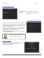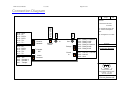
1
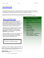
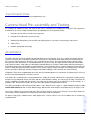
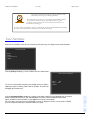
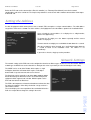
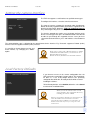
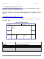
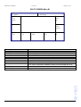
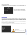
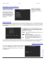
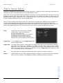
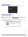
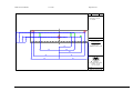
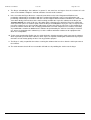
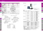
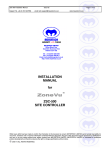
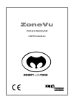
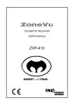
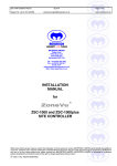
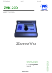
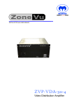
USER and CONFIGURATION MANUAL ZVR-130 Telemetry Receiver and camera interface Issue 05 Contents SAFETY PRECAUTIONS ....................................................................................................................................................................................... 3 INTRODUCTION ..................................................................................................................................................................................................... 4 ZVR-130 OVERVIEW.............................................................................................................................................................................................. 5 TELEMETRY DATA NETWORK............................................................................................................................................................................. 6 CAMERA HEAD PRE-ASSEMBLY AND TESTING................................................................................................................................................ 7 CONFIGURING THE ZVR-130.............................................................................................................................................................................. 11 ZVR-130 LOGIN ................................................................................................................................................................................................... 15 MAIN MENU ......................................................................................................................................................................................................... 15 DISPLAY SETUP MENU ...................................................................................................................................................................................... 16 ALARM SETUP MENU ......................................................................................................................................................................................... 20 INSTALLATION MENU......................................................................................................................................................................................... 22 AUDITING MENU ................................................................................................................................................................................................. 23 APPROVALS AND STANDARDS ........................................................................................................................................................................ 24 SPECIFICATION .................................................................................................................................................................................................. 25 MOUNTING TEMPLATE ....................................................................................................................................................................................... 28 SERVICING AND SUPPORT ................................................................................................................................................................................ 30 WARRANTY ......................................................................................................................................................................................................... 32 Safety Precautions 1. Carefully read this Product Manual prior to commencing installation and configuration. 2. Before working on this product, power it down and remove the power leads. Removing the module or PCB’s from their environmental enclosure may cause damage to the product and present an electric shock and fire hazard. 3. To reduce the risk of electric shock and fire hazard do not operate this product without the protection of a suitable environmental enclosure. 4. Do not install or operate the product near water. 5. Do not install or operate this equipment outside, unless it is fitted inside a suitable environmental enclosure E.G. IP rated camera housing. 6. Only install this equipment into a suitable environmental enclosure. 7. If work is carried out on the product with environmental enclosure panels and covers removed ensure full electrostatic handling procedures are adhered to. 8. Ensure the product is operated in a suitably temperature controlled environment within the specification limits. 9. Do not operate the product in humidity greater then 90%. 10. Do not drop objects of any kind onto the product when installing it. This may cause electric shock, fire hazard or product malfunction. 11. Avoid liquid spillages on the product. This may cause electric shock, fire hazard or product malfunction. 12. Never attempt to service this product yourself. This product contains no serviceable parts. Refer all servicing requirements to the Meyertech Service Centre or appointed Meyertech Service Agent 13. Do not operate this product if 13.1. Any product power leads are damaged. 13.2. If the product has been exposed to rain. 13.3. If the product has been dropped or the assembly has been damaged. 13.4. If liquid has been spilt on the product. 13.5. If the product has malfunctioned or is not operating to its functional specification. 14. This product must only be operated with the power supply provided or if supplied without a power supply, by the type of power source indicated in the specification. 15. Follow all warnings and instructions marked on the product and in this manual. . WARNING: This product may be used to switch hazardous mains voltages. When working on this product use extreme caution and observe Health and Safety at work practices. ! THIS PRODUCT MUST BE EARTHED! ZVR-130 User Manual Issue 05 Page 4 of 33 Introduction Thank you for purchasing this product. The following instructions will guide you through the installation and configuration of your ZoneVu ZVR-130 telemetry receiver. Please carefully read the rest of this manual before attempting to operate this product. This will ensure that the best performance is obtained. Meyertech’s ZVR-130 receiver continues in the tradition of Meyertech telemetry receivers. Building on the virtues of the ZVR-110 and features of the ZVR-530, the ZVR-130 does not disappoint. KEY FEATURES What is a ZVR-130? A fusing together of the ZVR-530 and ZVR-110 features made possible by the harnessing of leading-edge embedded CPU technology coupled with precisely developed firmware to deliver a blend of performance and refinement which will challenge your concept of camera control. Enhanced alarm management facilities now mean that alarms can be handled locally by the ZVR130, reported centrally to a site or reported Intersite when managed by the ZoneVu Site Controller family of products. With the complexity of today’s camera heads one of the ZVR-130’s raison d’etre is the ability to remotely configure and backup the plethora of features today’s digital cameras offer. The features described in this manual refer to : Version 1.6.0.1 of the ZVR-130 firmware The information in this manual is believed to be accurate and reliable. However, Meyertech Limited assumes no responsibility or liability for its use, or for any infringement of patents or other rights of third parties, which may result from its use. No license is granted by implication or otherwise under any patent or other rights of Meyertech. All specifications are subject to change without prior notice. MEYERTECH LIMITED are committed to continuous product development and therefore reserve the right to change specifications without notice. 2003-14 ALL RIGHTS RESERVED. • Compact camera housing design • 2-wire or 4 wire • Support for digital camera configuration and backup • 2 Relays • Static captions • 3 Contact alarms • Video loss alarm • Local alarm handling • Remote alarm reporting • Diagnostic facilities • Remote configuration and backup via Meyertech’s Mpower software • 16-bit embedded processing power ZVR-130 User Manual Issue 05 Page 5 of 33 ZVR-130 Overview The ZoneVu ZVR-130 telemetry receiver is a composite assembly comprising four PCBs: P104 PCB Microprocessor board P114 PCB Motherboard The P104 board contains the CPU, ROM and RAM circuitry. It is a SMD multi-layer PCB. The P114 is the Motherboard. It contains the power circuitry, glue logic, serial communications ports, alarm processing circuitry and various relays for camera auxiliary functions. The P104 plugs into the P114 and secures with screws. The whole ZVR-130 assembly is mounted onto an aluminium bracket. The bracket serves three purposes: 1. The easy to install bracket incorporates universal mountings allowing it to be mounted either horizontally or vertically. 2. It acts as a heat sink for the various PSU components. It also provides an earth bonding point. 3. Provides mechanical rigidity for the ZVR-130 assembly. ZVR-130 5 ZVR-130 User Manual Issue 05 Page 6 of 33 Telemetry Data Network The ZoneVu telemetry data network can be either RS422 (4 wire) or RS485 (2 wire) and either Simplex or Half-Duplex. Depending on which type of network you have or intend to have will determine how the receivers will be connected. For an RS485 network, the receivers MUST be wired in a ‘daisy-chain’ fashion to preserve the characteristics of the RS485 network. RS422 is generally more tolerant and in some circumstances can be either ‘daisy-chain’ or ‘star’ wired. Correct Termination of the data line is also very important to prevent ‘standing waves’ and reflection: 1. For RS422 daisy chain connection, terminate the last ZVR-130 RX input on the line into 120R. 2. For RS485 daisy-chain connection, terminate the last ZVR-130 RX input on the line into 120R. 3. For RS422 star connection, terminate all ZVR-130 RX input’s on the line into 120R x the number of receivers connected EG for 10 receivers terminate each one into 1K2 and ensure the on-board ZVR-130 termination is switched off on all receivers. Note the ZVR-130 has an on board 120R termination resistor which can be remotely switched on or off. The ZoneVu equipment driving the telemetry network will be one of the following models: ZVM-164 which can drive up to 16 ZVR-130’s RS422 simplex only ZVM-328 which can drive up to 32 ZVR-130’s RS422 simplex only ZSC-500 which can drive up to 128 ZVR-130’s RS422 simplex/half duplex RS485 half duplex ZSC-1000 which can drive up to 256 ZVR-130’s RS422 simplex/half duplex RS485 half duplex ZVS-MSI-48 which can drive up to 192 ZVR-130’s RS422 simplex/half duplex RS485 half duplex ZVK-007 which can drive up to 64 ZVR-130’s RS422 simplex only ZVK-77D which can drive up to 64 ZVR-130’s RS422 simplex only It should be remembered at this point exactly how important the network cabling is to the overall performance of any system and, indeed to the quoted performance of any particular piece of equipment connected to the network, including telemetry receivers. Care should therefore be taken to plan cabling routes properly and the use of the correct type of data cable is imperative. Meyertech recommend: RS422 / RS485 - Beldon 1-pair 9841, 2-pair 9502, 1-pair 8761 or equivalent ZVR-130 A common misconception with RS422 and RS485 networks is that no 0V connection is required between the transmitting equipment and the receiving equipment, and that only the data pair is required! Well actually this WILL work on your bench, but when you come to install it in the field it may or may not work. The reason for this is basic electrical principles. It will work on the bench because the earth potential difference will be within that specified by the IC manufacturers. In the field it may well be outside the specification, all be it intermittently. Any electrical circuit requires a ‘return-path’ to work. On the bench this is achieved via the mains earth circuit. In the field there maybe a potential difference between the two earth points of 50 volts or more, which is well outside the IC specification for it to function correctly. Normally the outer screen of the data cable can be used as the 0VDC cable but in noisier environments it is important to use a separate cable even If it means a third pair. In this instance the outer shield should be connected to ‘dirty’ earth at one end only! VICTA-ZoneVu ‘down the coax’ telemetry, is not directly supported by the ZVR-130. If you want to be able to control the ZVR-130 via VICTA (which may be the case if you are using a ZVM-328 matrix) you will require a ZVD-V42-ZV VICTA to RS422 ZoneVu driver module, which should be located at the receiver end. Note. When controlling the ZVR-130 via VICTA certain advanced feature and functionality will not be available EG alarm reporting, camera configuration ETC. 6 ZVR-130 User Manual Issue 05 Page 7 of 33 Turnaround time The ZVR-130 has a data turnaround time of approximately 1ms Camera Head Pre-assembly and Testing It is important to consider the time and expense that can be saved by pre-assembling and testing the ZVR-130 prior to installation on-site. Pre-assembly normally involves the following tasks (in no particular order): 1. Fixing the camera and lens into the camera housing. 2. Fixing the ZVR-130 into the camera housing. 3. Producing the wiring harness for the ZVR-130, auxiliary devices (e.g. wiper, heater or lamps) and Camera. 4. Initial self test 5. Network configuration and testing Installation The ZVR-130-PCB has been designed to be installed within the camera housing. There are a number of technical and nontechnical reasons for this. Firstly from a performance perspective it is important to understand that the best performance of the receiver is achieved when it is located as close as possible to the camera. The reasoning behind this is that the further away the ZVR-130 is located E.G. in a weatherproof box tens of meters away, the longer the cable needed to connect back to the camera functions. Long cable runs will introduce potential differences and noise, both of which will affect performance. Secondly the temperature and humidity are controlled inside a camera housing which is a good environment for the ZVR-130 to live in. Thirdly the appearance of the complete camera head assembly is cleaner and more aesthetically pleasing. Finally it will save you money! Meyertech therefore strongly recommend installing the ZVR-130 inside the camera housing. Installing the ZVR-130 is straightforward due to the universal mounting bracket it is attached to. A template for the universal bracket can be found towards the end of the manual. If the ZVR-130 is installed inside a weatherproof box the cabling to the ZVR-130 MUST be segregated according to their function E.G. you would not want to mix mains with the communications cabling. The correct type of cables should also be chosen according to function EG you would a coax cable for the video. Never be tempted to run all the functions in a multicore cable. To help wire the ZVR-130 use the connection diagram provided with this manual. The ZVR-130 should be powered from 24VAC 50Hz +/-10%. Meyertech can supply, a suitable toroidal transformer, Part number ZVR-130-PSU, or from a 12Vdc, 600mA supply. Note that the 12Vdc output is not available unless AC input is used. Once all the cabling has been connected to the ZVR-130 and camera it can be tested using the self-test which allows the receiver to be exercised without the need for it to be connected to a ZoneVu controller. ZVR-130 To do this simply plug a monitor into the video output of the receiver and press the self-test button once to activate the Installation Menu. 7 ZVR-130 User Manual Issue 05 Page 8 of 33 Navigation of the menus using the self-test button is easily achieved by following these simple guidelines Press and release the button once to display the Installation Menu. To cycle down the menu press and release the button again. To select a menu option press and hold down the button for a second before releasing it. To exit a menu or complete a setting, cycle through the menu until FINISH starts flashing. Now press and hold down the button for 1sec before releasing it. Test Facilities From the Test Facilities menu you can manually test the two relays, the display or the communications. TEST FACILITIES Relays Display Communications FINISH Selecting Relays will display a menu similar to the one shown below. RELAY TEST FACILITIES To exercise each function manually cycle through the menu until the option you require is flashing. Now select the function. The ZVR-130 will toggle the function once. Relay 1: OFF Relay 2: OFF FINISH 8 ZVR-130 Selecting Communications will display a further menu with the option to select Network port or SIP port. Before selecting the port to test, you should bridge the Receive & Transmit together for that port. When started the receiver performs a short loopback test on the selected port. If the test data is correctly received a ‘PASSED’ message is displayed, else the receiver shows ‘FAILED’. Press the button to return to the Communications test menu. ZVR-130 User Manual Issue 05 Page 9 of 33 Before the ZVR-130 can be connected to a ZoneVu controller (see Telemetry Data Network) some basic network configuration needs to be carried out. The simplest way to do this is on the bench with a monitor connected the video output of the ZVR-130. Setting the Address As with all equipment which communicates over a network, ZVR-130 requires a unique network address. The valid address range for the ZVR-130 is 1 to 4096. To set the address, first highlight and select the Address option in the Installation Menu. INSTALLATION MENU Address Test Facilities Network Settings Serial camera Factory Settings FINISH : 0006 Once selected the current address is re-displayed as a 4-digit number, with the first digit flashing. To change the first digit, press the button repeatedly until the correct number is displayed. To move onto the next digit, press and hold the button down for 1 second. After the last digit has been changed, press and hold the button down for 1 second to return to the installation menu. The address is set immediately. If you make a mistake, simply repeat the procedure. Network Settings The network settings of the ZVR-130 can be configured to interface to different types of data transmission network. Both the network type and BAUD rate can be altered here. Navigate the menu as previously to select and configure each setting. The MODE can be set to either RS485, which requires a single half-duplex data link or to RS422 which requires a full-duplex data link with a separate transmit and receive channel. The Baud rate can be manually set to either 9600, 19200 or 38400 Baud. Alternatively the Baud rate can be set to auto for Meyertech equipment which supports auto selection. With this option set the ZVR-130 auto detects the Baud rate. The ZVR-130 incorporates on-board termination to terminate the data line when the network is either daisy chained or a single receiver is connected to a driver. The menu displays the current position of the termination link on the PCB. It is not possible to change this setting in the menu. NETWORK SETTINGS Mode Baud Rate Termination FINISH : RS485 : 9600 : On ZVR-130 9 ZVR-130 User Manual Issue 05 Page 10 of 33 Setting the camera interface The ZVR-130 supports a serial interface to specified camera types. SERIAL CAMERA To configure this interface, select the Serial Camera menu. Camera Type Mode FINISH : JVC : RS422 The range of cameras supported is constantly under development. Details of currently supported models and features supported can be found in the Meyertech document ZVR-x30 Supported Cameras or by contacting the Meyertech sales department. To select the protocol you require, press the button until you reach the line “Camera type” then press and hold the button. You will now be able to cycle through the supported cameras. Once you have selected the desired interface, press and hold the self test button to save. The communications type is defaulted to the normal format for the interface. E.g. Panasonic support an RS485 (2-wire) interface and JVC support an RS422 (4-wire) interface. It is possible to change between 2-wire and 4-wire formats, by changing the “Mode” option. When using a camera with a RS-232 interface i.e. Philips LTC0500 or LTC0600 cameras you will need to use a RS-422 to RS-232 converter. Within the menu, RS-422 format should be selected. Load Factory Defaults LOAD FACTORY DEFAULTS should only be done as Cancel Confirm If you become unsure of the current configuration then the ZVR-130 can be restored to it’s factory settings. This should only be done as a last resort though because ALL previously configured data will be lost. IE factory defaults will be restored including the address. To load factory defaults select Confirm, otherwise select Cancel to return to the Installation Menu. When you use the self-test button to load factory defaults, ALL configured data is lost, including the receiver address. 10 ZVR-130 When you load factory defaults over the network, IE when the ZVR-130 is connected to a ZoneVu network the receiver address is not restored to its default value. This may save you a trip out to the receiver site! ZVR-130 User Manual Issue 05 Page 11 of 33 Configuring the ZVR-130 The advanced features of ZVR-130 configuration are achieved when connected to a ZoneVu controller. This maybe in a ZoneVu system on-site or when connected directly to a keyboard. To configure the advanced features of the ZVR-130 you will require access to a System keyboard such as the ZVK-007 or ZVK-77 connected either directly to the receiver or via a ZoneVu controller such as the ZSC-1000 or ZVM-328. When connected via a video matrix be sure to first select the receiver to a monitor within your view as configuration is via on screen menus. Configuration using a ZVK-77 To configure the ZVR-130 using a ZVK-77 system keyboard you will first need to access the two ZVR Config. Menus shown below. To do this you will need to log onto the keyboard at the relevant level which permits access to the Program / Setup option. For further details please refer to the relevant section in the ZVK-77 User and configuration manual for how to access the ZVR Config. Menus. ZVK-77 LCD SCREEN (Menu A) Engineer Type ZVR-x30 ZVR Config Site (local) Monitor 1 Camera 1 Start Config Change Monitor Select Site Toggle Pot Display Select Site Toggle pot display Description The name of the current user logged onto the ZVK-77 The current menu Press this to cycle through the receiver types Select to start configuration Select this option if you wish to configure a different ZVR-130 Select this option if you want to change to display the ZVR-130 menus on a different monitor Select this option if you want to configure a ZVR-130 on a different site Turn on the displaying of the feedback potentiometer values ZVR-130 Menu Option Engineer ZVR Config. Type ZVR-x30 Start config Select Camera Change Monitor Select Camera 11 ZVR-130 User Manual Issue 05 Page 12 of 33 ZVK-77 SCREEN (Menu B) Engineer ZVR Config Last Menu Restart config Enter caption Left Menu Option Engineer ZVR Config. Last Menu Left Up Select Down Right Enter caption Restart config Site Up Select Down Right Description The name of the current user logged onto the ZVK-77 The current menu Select to display the last ZVR-130 configuration menu (or exit) Navigate the on screen menu. Move Left Navigate the on screen menu. Move Up Select the menu option Navigate the on screen menu. Move Down Navigate the on screen menu. Move Right This option only applies when a caption option has been selected from the receiver menu. It gives an alternative method to selecting each letter through the menu. Return to the top level menu Displays the current site you are on ZVR-130 12 ZVR-130 User Manual Issue 05 Page 13 of 33 Configuration using a ZVK-007 To configure the ZVR-130 using a ZVK-007 system keyboard you will first need to access the ZVR Config. Menu . To do this you will need to log onto the keyboard at the Supervisor Level, which permits access to programming functions such as ZVR Config. For further details on how to do this please refer to the relevant section in the ZVK-007 User Manual. Then follow the ‘ZVK-007 Users Manual-Addendum’ instructions given below. Note the ZVK-007 refers to the ZVR-530. ZVK-007 USERS MANUAL ZVR CONFIG allows camera receivers to be configured from the comfort of the keyboard by utilizing the camera receiver OSD (On Screen Display) The display will show STEP 1 SUPERVISOR CONFIGURATION LEVEL ZVR CONFIG Press the ENT key the display will show SUPERVISOR 510 CONFIG MONITOR-1 LEVEL ESC TO EXIT CAMERA -1 STEP 2 Select the camera you want to configure using the numeric keypad and pressing the ENT key. STEP 3 Press the MODE key. The display will change to SUPERVISOR 510 CONFIG MONITOR-1 LEVEL PROG TO SELECT CAMERA -1 STEP 4 Press the PROG key to select the type of receiver: ZVR-510, ZVR-130, or ZVR-500 STEP 5 Press the MODE key. The display will change to STEP 6 SUPERVISOR 530 CONFIG MONITOR-1 LEVEL PROG TO CONFIG CAMERA -1 Press the PROG key to access the camera receiver OSD. The display will show ACCESS GRANTED and then ZVR TALK MODE STEP 7-8 The operation of the menus varies according to the receiver type. STEP 7 Follow the OSD Menus to configure the camera receiver. 13 ZVR-130 ZVR-130 Navigation ZVR-130 User Manual Issue 05 Page 14 of 33 The currently selected option is shown in flashing text: Use UP and DOWN to move the selection, and press SELECT to choose the current selection. Selecting a menu displays different options, selecting an option allows it to be changed. Options, which require text or numeric input, will clear ready for input when selected. Otherwise the option toggles through the choices each time it is selected. Text and numbers can be entered directly from the keypad. The Shift key toggles between text and numeric modes and the DEC key between upper and lowercase text. To cancel input or return to the previous menu, use the CANCEL key. Note: using CANCEL in the main menu screen, exits configuration mode. STEP 8 When you have completed configuring the receiver, press the ESC key to exit ZVR CONFIG. ZVR-130 Menu Navigation UP DOWN LEFT RIGHT SELECT CANCEL ZVK-007 Key LIVE / Joystick up ENC / Joystick down / DEL PIP / Joystick left ACT / Joystick right ENT / Zoom in HOLD / Zoom out ZVR-130 14 ZVR-130 User Manual Issue 05 Page 15 of 33 ZVR-130 Login If the ZVR-130 Configuration Protection feature has been enabled you will see the menu below which asks you to enter a PIN. This feature protects the ZVR-130 from any unauthorised configuration. LOGIN Access Denied Enter PIN code: 8888 Using the Numeric keypad of your keyboard enter the PIN for that particular receiver. Failure to enter the correct PIN will result in the error message ‘Access Denied’ being displayed. If the ZVR-130 Configuration Protection feature is disabled the first menu you will see is the Main Menu. Main Menu The first menu you will see once you have successfully logged in is the Main Menu (shown below). From this menu you can access the rich array of features the ZVR-130 has to offer. Whenever you configure an option the ZVR-130 internal database is updated and the change takes effect immediately. All configuration data is stored in what is commonly referred to as nonvolatile memory, which simply means that when power to the ZVR-130 is removed the configuration data is not lost. Typically configured data in the ZVR-130 can be retained for up to ten years without loss! The latest generation of ZoneVu ZSC products allow the full ZVR-130 database to be downloaded to a PC using Mpower, a PC application which allows you to configure, backup and restore ZoneVu system data. Once downloaded the database can be archived for future use by service and maintenance personnel. Each option shown in the Main Menu will have a number of sub-menus associated with it. The number of sub-menus will depend on the complexity of the feature to be configured. You can exit ZVR-130 configuration from any menu, you do not have to return to the Main menu. MAIN MENU Display Setup Alarm Setup Relay Functions Installation menu Auditing When you change the configuration of a particular parameter, the implementation is immediate. 15 ZVR-130 Menus which have configuration data fields display the currently set status. ZVR-130 User Manual Issue 05 Page 16 of 33 Display Setup Menu The Display Menu allows you to configure the On Screen Display (OSD) features of the ZVR-130. DISPLAY MENU From this sub-menu you have options to program a descriptive camera caption, decide where the caption will be displayed on screen, where alarm information will be displayed, and the brightness of the overlay. Edit Caption Caption Display Alarm Display Command Display Set Display Area Set Text Colour Set Character Border Options are also provided to display telemetry command confirmation. Also the whole display area can be moved and it’s size set. Edit Caption A descriptive caption can be programmed into the ZVR-130 which is displayed at all times. The caption provides unique identification of the camera signal anywhere in the system. Another benefit of labelling the camera ‘at source’ is the caption is not susceptible to interference (often seen on the screen as tearing or bouncing captions) due to long cable runs and transmission paths. The caption can be up to 14 characters long. When you enter the Edit Caption menu a cursor will be flashing at the end of the current caption. To delete characters from the caption use the Clear button on the keyboard. Caption: Mtech ZVR-130 ABCDEFG H IJ KLMN OPQRSTU VWXYZ 0 1 2 3 456 7 8 9* . ‘ : + LOWER SPACE DONE QUIT LOWER – Select this option to toggle between Uppercase and Lowercase. SPACE - Select to insert a space DONE - When you are happy with the caption you have Entered select Done to save your new caption. You Will also be returned to the previous menu. QUIT - Lets you exit the menu without having to configure a New caption. As an alternative to selecting letters on the character grid on screen, the ‘Enter caption’ option on some keyboards allows the caption to be edited on the keyboard before being sent to the receiver. Don’t forget to delete the previous caption first ! Caption Display The caption can independently be configured to be displayed or not. simply select the Display option to toggle the caption On and Off. SETUP TEXT DISPLAY Display : ON Set Position 16 ZVR-130 The caption can be positioned anywhere on the screen using the Set Position option. ZVR-130 User Manual Issue 05 Page 17 of 33 Selecting Set Position will display the menu shown to the right. the text area display is configured as two columns of 14 characters each by 16 rows. The position of the caption can be moved to the desired position by using the navigation keys Down, Up, Left and Right. Text Position To exit the menu select either the Last Menu key or Cancel key. Alarm Display SETUP TEXT DISPLAY The Alarm Text can independently be configured to be displayed or not. Simply select the Display option to toggle Alarm Text On and Off. Display : ON Set Position The Alarm Text can be positioned anywhere on the screen using the Set Position option. Selecting Set Position will display the menu shown to the right. the text area display is configured as two columns of 14 characters each by 16 rows. The position of the Alarm Text can be moved to the desired position by using the navigation keys Down, Up, Left and Right. Text Position To exit the menu select either the Last Menu key or Cancel key. ZVR-130 17 ZVR-130 User Manual Issue 05 Page 18 of 33 Command Display SETUP TEXT DISPLAY Command Display refers to the displaying of camera commands as they are received from the ZoneVu controller as confirmation of the operator action. This display can be switched on or off. If you do not want to display the camera commands simply select the Display option to toggle the caption off, toggling it again will switch Display back on. Display : ON Set Position The Command Display can be positioned anywhere on the screen using the Set Position option. Selecting Set Position will display the menu shown to the right. The text area display is configured as two columns of 14 characters each by 16 rows. The position of the Command Display can be moved to the desired position by using the navigation keys Down, Up, Left and Right. Text Position To exit the menu select either the Last Menu key or Cancel key. Set Display Area Set Display Area allows the user to configure over what area of the monitor textual information will be displayed. The overall size and position of the OSD is indicated by the white chequered pattern. Using the navigation keys Down, Up, Left and Right, the display can be set to the particular size required. 18 ZVR-130 1 TO EXIT ZVR-130 User Manual Issue 05 Page 19 of 33 Set Text Colour Allows you to adjust the greyscale level of the captioning including all text on the screen. Sample text is displayed on the screen and you are prompted to ‘Pan to change colour’. The left & right keys can also be used. The current colour setting is also displayed in the range 0 to 15. Moving left or right increases or decreases the colour setting & updates the sample text in real time. Set Character Border Adjusts the greyscale level of the fringing around the edges of each character. Sample text is displayed on the screen and you are prompted to ‘Pan to change colour’. The left & right keys can also be used. The current colour setting is also displayed in the range 0 to 15. Moving left or right increases or decreases the colour setting & updates the sample text in real time. WARNING: Character Colour & Border affects all text display from the receiver. Setting both to a shade indistinguishable from the background will result in the inability to view the setup menus. ZVR-130 19 ZVR-130 User Manual Issue 05 Page 20 of 33 Alarm Setup Menu Provided as standard on the ZVR-130 are two contact type alarm inputs, a dedicated Tamper contact type alarm input and a video fail alarm, which automatically detects the loss of video from the camera. Alarm inputs can be independently configured to trigger on contact closure or contact opening. Each alarm input can also be disabled to eliminate false alarms when work is being carried out in the alarmed area. When an alarm occurs the programmed alarm caption is displayed on screen. If more than one alarm is active at any one time the OSD cycles between the alarm captions displaying each one in turn for a period of time. Alarms can be managed centrally when the ZVR-130 is connected to a ZSC-500 or ZSC-1000 ZoneVu Site Controller. For example certain alarm inputs may require the action of another camera to provide full coverage of the incident. In this instance the ZSC-XXXX would be configured to request alarm status from the camera on a regular basis. Upon receipt of the alarm the ZSC-XXXX could instruct a PT camera to recall a preset or execute a patrol to monitor the area in alarm. ALARM MENU Alarm Trigger State - Used to select one of the four alarms available, Tamper, Alarm 1, Alarm 2 and Video Loss. Press the Select key to cycle through the and view the settings of each alarm. To configure alarm input settings, first cycle through until the alarm you wish to configure is displayed, then select the option you wish to change. Alarm : Tamper Trigger State : Closed Trigger Time : 50mS Text : Tamper Display : Enabled - Use the Select key to set the Trigger State to either Closed, Disabled or Open. Trigger Time - The Trigger Time parameter is used to reduce the number of false alarms due to ‘contact bounce’ from the alarm source. The trigger time is important as it validates the alarm source. After the alarm is initially triggered the source is checked again after the Trigger Time. If the alarm is STILL triggered after the Trigger time has elapsed the alarm is accepted as a valid alarm. To set the Trigger Time select Trigger Time and enter a time period in the range of 10 to 990ms. Text - Each alarm input can be programmed with its own unique text label (14 characters maximum) Display - Using this option you can enable and disable the Alarm Text display. If set to on the alarm Text is displayed when an alarm is activated. Use the Select key to Enable and Disable the display of alarm text. ZVR-130 20 ZVR-130 User Manual Issue 05 Page 21 of 33 Relay Functions The ZVR-130 has at its disposal two relays. The relays are identical (refer to ZVR-130 specification) and are all have volt-free contacts. Configuration options allow the user to ‘map’ each of the relays to a particular camera command E.G. map relay 2 to the command Wiper. After mapping, the function can be labelled. The operation of each relay can also be configured to set the Timeout and Repeat periods. This flexible approach to relay use provides the installer with a plethora of interface and control options in the field. RELAY FUNCTIONS MENU Relay Command On text Off text Timeout Repeat time Time units : : : : : : : 1 Wash Wash Relay - Used to select one of the two relays available, Relay 1, and Relay 2. Press the Select key to cycle through and view the settings for each relay. To configure a Relay’s settings, first cycle through until the relay you wish to configure is displayed, then Select the option you wish to change. Momentary 0Min Minutes Command - Use the Select key to cycle through and map the command from the options Wash, Iris mode, Aux 1, Aux 2, Aux 3, Wiper and Lamp On Text - Program a text label for the Relay function. Default text describes the default function E.G. command=Wiper; On text=Wiper On. To configure your own label press Select to display the alphanumeric on-screen keypad. Off Text - Program a text label for the Relay function. Normally this is left blank for momentary functions. Default text describes the default function E.G. command=Wiper; On text=Wiper On. To configure your own label press Select to display the alphanumeric on-screen keypad. Timeout - The Timeout period is the time the relay is switched on for in ‘Time Units’. It can be set to in the range 0 to 250 time units. Set to 0 for momentary action. Repeat Time - The repeat time can be set to generate a pulsed output stream. Set to 0 for latched commands. Time Units - Time units can be set as either seconds or minutes. Use the Select key to toggle between the two. ZVR-130 21 ZVR-130 User Manual Issue 05 Page 22 of 33 Installation Menu Selection of this option will take you to a minor variation of the installation menu selected with the self test button. INSTALLATION MENU Address Network Settings Serial Camera Factory Settings : 6 Serial Camera Interface The ZVR-130 supports a serial interface to specified camera types. To configure this interface, select the Serial Camera menu. The range of cameras supported is constantly under development. Details of currently supported models and features supported can be found in the Meyertech document ZVR-x30 Supported Cameras or by contacting the Meyertech sales department. Select the ‘Camera Type’ option to cycle between the available interface types, to match the camera in use. The communications type is defaulted to the normal format for the interface. E.g. Panasonic support an RS485 (2-wire) interface and JVC support an RS422 (4-wire) interface. When using a camera with a RS-232 interface i.e. Philips LTC0500 or LTC0600 cameras you will need to use a RS-422 to RS-232 converter. Within the menu, RS-422 format should be selected. ZVR-130 22 ZVR-130 User Manual Issue 05 Page 23 of 33 Auditing Menu AUDIT MENU Change Pin Number : Select this option to enter a new PIN. Change Pin Number System Info System Info. : This option displays information about the ZVR-130. Change PIN Number The ZVR-130 can be programmed with a PIN to protect it from unauthorised Configuration. PIN security is activated whenever a configuration request is received. The operator is then requested to enter a receiver PIN. If the PIN Is incorrect access will be denied. Enter PIN code: 8888 The PIN can be up to six digits long. All ZVR-130’s are shipped from the factory with configuration login disabled I.E. PIN set as zero. To enable configuration login enter any new PIN other than zero. To enter a new PIN Select the option and enter a number up to six digits long using the numeric keypad. CAUTION ! If you decide to use the ZVR-130 Configuration login protection ensure you keep a record of the PIN. Failure to do so may result in having to load factory defaults if the PIN is forgotten. System Info. Selecting the System Info. option displays the following screen giving details of the receiver address, firmware version and network communications settings. MEYERTECH LIMITED ZVR-130 Telemetry Receiver Mode : RS485 9600 Baud Termination : OFF 23 ZVR-130 Address : 6 Version 1.6.0.1 ZVR-130 User Manual Issue 05 Page 24 of 33 Approvals and Standards MEYERTECH LIMITED Zebra Court White Moss View Greenside Way Manchester M24 1UN Tel: +44 (0)161 643 7956 Fax: +44 (0)161 643 3992 Email: [email protected] http://www.meyertech.co.uk EC DECLARATION OF CONFORMITY ACCORDING TO ARTICLE 10 OF COUNCIL DIRECTIVE 89/336/EEC MEYERTECH LIMITED DECLARE UNDER OUR SOLE RESPONSIBILITY THAT THE PRODUCT TO WHICH THIS DECLARATION RELATES, IS IN CONFORMITY WITH THE PROTECTION REQUIREMENTS OF COUNCIL DIRECTIVE 89/336/EEC ON THE APPROXIMATION OF THE LAWS OF THE MEMBER STATES RELATING TO ELECTROMAGNETIC COMPATIABILITY. THIS DECLARATION OF CONFORMITY IS BASED UPON COMPLIANCE OF THE PRODUCT WITH THE FOLLOWING HARMONIZED STANDARDS. EN55022 CLASS B EN50093 PRODUCT ZVRZVR-130 Telemetry Receiver ZVR-130 For Meyertech Limited S K MEYERS Managing Director ISSUED THIS DAY 12/03/2014 24 ZVR-130 User Manual Issue 05 Page 25 of 33 Meyertech Limited is a member of the CCTV Manufacturers and Distributors Association Meyertech Limited is a member of the CCTV User Group. Specification Operating temperature range Enclosure Dimensions Weight PSU 12V DC Output ZoneVu Network Port Serial Integration Port 1 (SIP1) 0 to +50 deg. C Universal mounting bracket open frame. ZVR-130 assembly mounted on universal bracket, which can be installed either vertically or horizontally. Universal bracket colour – Silver W175mm D87mm H39mm 300g including universal bracket 24V AC +/-10% 50-60Hz 250mA (excluding 12V DC output) 12V DC 180mA operating, 220mA power-up surge 750mA @ 12V DC +/-15% Not available from 12V DC input RS422 / RS485 half duplex or simplex RS422 – RS485 – half duplex or full duplex Alarm Inputs Tamper and two contact type N/O or N/C plus alarm common – Video loss. Sync. monitoring Diagnostic LED’s +12V and CPU (heartbeat), ZoneVu Network Communications Tx and Rx, Serial Integration Port Tx and Rx OSD Camera captions – Configuration Menus – Alarm captions – Command captions Functions Connectors Video Connectors Features 25 ZVR-130 Video Inputs Video Outputs Relay 1 Two columns of 14 characters per column. 16 rows. Miniature Klippon 2-part 3 to 8 BNC Aux 1 to Aux 2 - Diagnostics - Camera fail alarm - Alarm inputs – contact - Static caption - Configuration, menu driven – Configuration, direct command - Global - On Screen Display – Camera configuration management - Auto timeout facilities Multiple Baud rate support - Re-settable PSU fuse - Alarm reporting management - Address range 1 -4096 1V p-p 75R terminated. PAL CCIR 1V p-p 75R impedance. PAL CCIR NC or NO volt free contacts 1A 30V AC/DC ZVR-130 User Manual Relay 2 Issue 05 Page 26 of 33 NC or NO volt free contacts 1A 30V AC/DC ZVR-130 26 ZVR-130 User Manual Issue 05 Page 27 of 33 Connection Diagram Issue Change Date 1.0 Draft pin 5 - 0V pin 4 - RxTx+ pin 3 - RxTxpin 2 - Tx+ pin 1 - Txpin 4 - 12v pin 3 - Contact 2 pin 2 - Contact 1 pin 1 - Tamper 6 5 4 3 2 1 ZoneVu Network 12 Camera Power BNC 1.2 Revised for clarity, pin out same as description fields. BNC pin 6 - Gnd pin 5 - 0v pin 4 - RxTx+ pin 3 - RxTxpin 2 - Tx+ pin 1 - Tx - Pin 1 - 12V DC Pin 2 - 0V DC 1.1 Revised to fit issue 2 of PCB. Video In Video Out Relays 5 4 3 2 1 Camera SIP 4 3 2 1 Alarm Contacts Power In 1 2 3 4 5 6 1 2 3 2.0 Changes for P114-004 pin 1 - Relay 1 Common pin 2 - Relay 1 N/O pin 3 - Relay 1 N/C pin 4 - Relay 2 Common pin 5 - Relay 2 N/O pin 6 - Relay 2 N/C Description Connection Diagram pin 1 - 24v AC / +12v DC pin 2 - 24v AC pin 3 - Gnd MEYERTECH LIMITED OFFICE BLOCK ONE SOUTHLINK BUSINESS PARK OLDHAM OL4 1DE TEL: 0161 628 8406 Drwg. No. ZVR130_Bracket-AE ZVR-130 User Manual Issue 05 Page 28 of 33 Mounting Template Issue Use these templates to mark and drill the mounting holes for the universal mounting bracket. The bracket can be mounted st horizontally (1 template), or vertically nd (2 template). 1.0 Change Date Draft 1.1 Revised to fit issue 2 of PCB. 1.2 Revised screw holes to fit PCB dimensions. 6 32 51 62 80 The mounting screws provided are type M4 that require a 4.5mm clearance hole. 53 84 53 84 MEYERTECH LIMITED OFFICE BLOCK ONE SOUTHLINK BUSINESS PARK OLDHAM OL4 1DE TEL: 0161 628 8406 Drwg. No. ZVR130_Bracket-AD ZVR-130 User Manual Issue 05 Page 29 of 33 Issue Change Date 1.0 Draft 1.1 Revised to fit issue 2 of PCB. 32 34 17 19 Description Front Elevation scale = 1:1 all dimensions in mm 36 60 48 68 80 88 80 88 MEYERTECH LIMITED OFFICE BLOCK ONE SOUTHLINK BUSINESS PARK OLDHAM OL4 1DE TEL: 0161 628 8406 Drwg. No. ZVR130_Bracket-AB 29 ZVR-130 User Manual Issue 05 Page 30 of 33 Servicing and Support Servicing The ZVR-130 requires no Planned Preventive Maintenance periods (PPM’s) as it is mainly solid state in design. However, the performance of the ZVR-130 may change over time due to changes in the equipment it is connected to. Therefore, Meyertech recommend checking the operation of functions, which drive mechanical components in accordance with normal PPM periods. The ZVR-130 contains no serviceable parts and should be returned to our Service Centre in Scunthorpe for repair or replacement under warranty. Any repairs, attempted repairs or replaced components not carried out by the Meyertech Service Centre will void all Meyertech warranties and liabilities. If your ZVR-130 has to be returned to our Service Centre please follow the returns procedure below, otherwise delays may be incurred in returning or replacing the ZVR-130. ZVR-130 User Manual Issue 05 Page 31 of 33 Support At Meyertech our staff understand quality support is important to you, vital in fact, which is why we place such a high precedence on providing it. For all matters relating to support go to our website to find the information your require visit http://www.meyertech.co.uk/support.html Disposal There are no additional requirements beyond safe working practice in the decommissioning of the Meyertech ZVR-130. However the ZVR-130 contains printed circuit boards populated with electronic components. The whole unit must be returned to Meyertech Service Centre for final disposal. Please follow the normal returns procedure. 31 ZVR-130 User Manual Issue 05 Page 32 of 33 Warranty Please refer to Meyertech Limited ‘Terms & Conditions of Sale of Goods & Services’ for interpretation. 1. If the Buyer establishes to the Seller's reasonable satisfaction that there is a defect in the materials or workmanship of the Goods manufactured, then the Seller shall at its option, at its sole discretion and within a reasonable time, a. arrange for the repair or making good such defect or failure in such Goods free of charge to the Buyer (including all costs of transportation of any Goods or materials to and from the Buyer for that purpose), b. replace such Goods with Goods which are in all respects in accordance with the Contract, or subject, in every case, to the remaining provisions of this Condition 1 provided that the liability of the Seller under this Condition 1 shall in no event exceed the purchase price of such Goods and performance of anyone of the above options shall constitute an entire discharge of the Seller's liability under this warranty. 2. Condition 1 shall not apply unless the Buyer: a. notifies the Seller in writing of the alleged defect within 12 (twelve) months from delivery or such other period or periods as may be agreed in writing between the Seller and the Buyer, and b. allows the Seller a reasonable opportunity to inspect the relevant Goods. 3. For the avoidance of doubt, the Seller shall be under no liability under the warranty in Condition 1 above: a. where such defects arise from any drawing, design or specification supplied by the Buyer; or b. where such defects arise from fair wear and tear, wilful damage, or negligence of a party other than the Seller (or its employees or authorised personnel), abnormal working conditions, failure to follow the Seller's instructions (whether oral or in writing), misuse or alteration or repair of the Goods without the Seller's approval; or c. where such defects arise in parts, materials or equipment which have not been manufactured or designed by the Seller but have been purchased at the Buyer's request by the Seller from the Buyer's designer and manufacturer or from some other third party (the “Third Party Supplier”). d. if the total price of the Goods has not been paid by the due date for payment e. in respect of any type of defect, damage or wear specifically excluded by the Seller by notice in writing: or f. if the Buyer makes any further use of the Goods after giving notice in accordance with Clause 1 4. Any repaired or replaced Goods shall be redelivered to the Buyer free of charge to the original point of delivery but otherwise in accordance with and subject to these Conditions. 5. Alternatively to Condition 1 the Seller shall be entitled at its absolute discretion on return of the defective Goods to the Seller (at the Seller's request) to refund the price of the defective Goods in the event that such price shall already have been paid by the Buyer to the Seller, or, if such price has not been paid, to relieve the Buyer of all obligation to pay the sum by the issue of a credit note in favour of the Buyer in the amount of such price. 6. In respect of all Goods supplied to the Seller by a Third Party Supplier the Seller will on request pass on to the Buyer (in so far as reasonably possible) the benefit of any warranty given to the Seller by such Third Party Supplier and will (on request) supply to the Buyer details of the terms and conditions of such warranty and copies of any relevant product information sheets, technical data sheets or product leaflets issued by such Third Party Supplier and the Buyer shall be solely responsible to the entire exclusion of the Seller for complying with the same. 7. For the purposes of Condition 1 references to Goods shall be deemed to exclude software. 32 ZVR-130 User Manual Issue 05 Page 33 of 33 8. The Buyer acknowledges that software in general is not error-free and agrees that the existence of such errors in the Software Programs shall not constitute a breach of this Contract. 9. In the event that the Buyer discovers a material error which results in the Programmed Products not performing substantially in accordance with the Functional Specification, or the Licensed Programs not performing substantially in accordance with the relevant Program Documentation and notifies the Seller of the error within 90 days from the date of the Seller making available the respective software to the Buyer (the `warranty period") the Seller shall at its sole option either refund the price which the Buyer has paid to the Seller (or if such price has not been paid, relieve the Buyer of all obligations to pay the sum) in respect of the respective software or use all reasonable endeavours to correct by patch or new release (at its option) that part of the software which does not so comply provided that such non-compliance has not been caused by any modification, variation or addition to the software not performed by the Seller or caused by its incorrect use, abuse or corruption of the software by use of the software with other software or on equipment with which it is incompatible, 10. To the extent permitted by English law, the Seller disclaims all other warranties, with respect to the software which it provides pursuant to the Contract, either express or implied, including but not limited to any implied warranties of satisfactory quality or fitness for any particular purpose. 11. The Buyer is solely responsible for various scanning the software that it receives from the Seller pursuant to the Contract. 12. The Seller warrants that it will use reasonable skill and care in providing the Services to the buyer 33