1
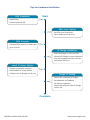
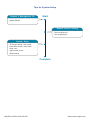
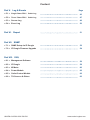
Inspired by Your Data Center
User Manual
IPM-04
PDU management software
W series PDU : Single Phase 250V
Three Phase 400V
Designed and manufactured by Austin Hughes
UM-IPM-04-250V-400V-Q215V1
www.austin-hughes.com
Legal Information
First English printing, October 2002
Information in this document has been carefully checked for accuracy; however, no guarantee is given to the correctness
of the contents. The information in this document is subject to change without notice. We are not liable for any injury or
loss that results from the use of this equipment.
Safety Instructions
Please read all of these instructions carefully before you use the device. Save this manual for
future reference.
■
■
■
■
■
■
■
■
■
■
■
Unplug equipment before cleaning. Don’t use liquid or spray detergent; use a moist cloth.
Keep equipment away from excessive humidity and heat. Preferably, keep it in an air-conditioned environment with
temperatures not exceeding 40º Celsius (104º Fahrenheit).
When installing, place the equipment on a sturdy, level surface to prevent it from accidentally falling and causing dam
age to other equipment or injury to persons nearby.
When the equipment is in an open position, do not cover, block or in any way obstruct the gap between it and the
power supply. Proper air convection is necessary to keep it from overheating.
Arrange the equipment’s power cord in such a way that others won’t trip or fall over it.
If you are using a power cord that didn’t ship with the equipment, ensure that it is rated for the voltage and current
labelled on the equipment’s electrical ratings label. The voltage rating on the cord should be higher than the one listed
on the equipment’s ratings label.
Observe all precautions and warnings attached to the equipment.
If you don’t intend on using the equipment for a long time, disconnect it from the power outlet to prevent being dam
aged by transient over-voltage.
Keep all liquids away from the equipment to minimize the risk of accidental spillage. Liquid spilled on to the power
supply or on other hardware may cause damage, fire or electrical shock.
Only qualified service personnel should open the chassis. Opening it yourself could damage the equipment and invali
date its warranty.
If any part of the equipment becomes damaged or stops functioning, have it checked by qualified service personnel.
What the warranty does not cover
■
■
■
Any product, on which the serial number has been defaced, modified or removed.
Damage, deterioration or malfunction resulting from:
Accident, misuse, neglect, fire, water, lightning, or other acts of nature, unauthorized product modification, or
failure to follow instructions supplied with the product.
Repair or attempted repair by anyone not authorized by us.
Any damage of the product due to shipment.
Removal or installation of the product.
Causes external to the product, such as electric power fluctuation or failure.
Use of supplies or parts not meeting our specifications.
Normal wear and tear.
Any other causes which does not relate to a product defect.
Removal, installation, and set-up service charges.
□
□
□
□
□
□
□
□
Regulatory Notices Federal Communications Commission (FCC)
This equipment has been tested and found to comply with the limits for a Class B digital device, pursuant to Part 15 of the
FCC rules. These limits are designed to provide reasonable protection against harmful interference in a residential installation.
Any changes or modifications made to this equipment may void the user’s authority to operate this equipment. This
equipment generates, uses, and can radiate radio frequency energy and, if not installed and used in accordance with the
instructions, may cause harmful interference to radio communications.
However, there is no guarantee that interference will not occur in a particular installation. If this equipment does cause
harmful interference to radio or television reception, which can be determined by turning the equipment off and on, the
user is encouraged to try to correct the interference by one or more of the following measures:
■ Re-position or relocate the receiving antenna.
■ Increase the separation between the equipment and receiver.
■ Connect the equipment into an outlet on a circuit different from that to which the receiver is connected.
UM-IPM-04-250V-400V-Q215V1
www.austin-hughes.com
Unpacking
The equipment comes with the standard parts shown on the package contents. Check and make sure they are included and in good
condition. If anything is missing, or damage, contact the supplier immediately.
All electrical power and power control wiring must be installed by a qualified electrician
and comply with local and national regulations.
Don’t exceed the outlet, branch or phase limitations
Power ON
■ Connect the PDU into an appropriately rated receptacle
■ When the PDU is power on, the LED display will light up. That means all outlets are activated
■ Keep the equipments in the power off position until it is plugged into the PDU
UM-IPM-04-250V-400V-Q215V1
www.austin-hughes.com
Tips for hardware Installation
PDU Installation
Start
- Install PDUs
- Connect power & ON
PDU Level Setting
- Set PDU level from meter
- Never duplicate the level no.
PDU Cascade
- Cascade PDU (meter) via LAN cable
- Up to 16 level
IP Dongle Installation
- Place IP Dongle on 1st level PDU
- Connect IP Dongle to meter LINK port
- Plug the bundled terminator into last
level meter OUT port
Install IP Setup Utilities
- Prepare a notebook computer
- Download the IP setup utilities
- Configure the IP Dongle one by one
Dongle IP Setting
- Search the connected IP Dongle
- Set password & IP address
- Set subnet & gateway
- Repeat the steps for other IP Dongle
one by one
Complete
UM-IPM-04-250V-400V-Q215V1
www.austin-hughes.com
Tips for System Setup
Prepare a Management PC
Start
- Install IPM-04
Remote Access Setting
- Set incoming port
- Set outgoing port
System Setup
- IP Dongle setting, User setup
- Auto data refresh / auto scan /
temp. unit
- alarm email server
- Data backup
Complete
UM-IPM-04-250V-400V-Q215V1
www.austin-hughes.com
Content
Part I. “ W “ Meter
Page
< 1.1 > Meter Key Features
1
< 1.2 > Meter Reading & Setting
- Single Phase PDU
3
< 1.3 > Meter Reading & Setting
- Three Phase PDU
7
< 1.4 > Meter ( PDU ) Cascade
12
< 1.5 > IP Dongle Installation
13
< 1.6 > Meter System Timer
14
< 1.7 > Optional Accessory
- Temp. Sensor / Temp. + Humidity Sensor
15
- Extended Door-mount Amp / Temp. Display
17
Part II. Software
< 2.1 > Key Features
19
< 2.2 > IP Dongle Configuration
20
< 2.3 > Hardware Requirements of the Management PC
21
< 2.4 > Supported OS Platform & Language
21
< 2.5 > Software Download
22
< 2.6 > First Time Start-up Setting
23
< 2.7 > Web Server Port no. Change
25
Part III. System Setup & Remote Access
< 3.1 > System Setup
26
< 3.2 > Remote Access
32
Part IV. Software Usage & Operation
< 4.1 > Status
33
< 4.2 > Details
34
< 4.3 > Outlet Setting
35
< 4.4 > Sensor status
36
< 4.5 > Sensor setting
37
< 4.6 > Outlet Schedule Overview
38
< 4.7 > Outlet Schedule Setting
39
UM-IPM-04-250V-400V-Q215V1
www.austin-hughes.com
Content
Part V. Log & Events
Page
< 5.1 > Single Phase PDU / Outlet Log
43
< 5.2 > Three Phase PDU / Outlet Log
47
< 5.3 > Sensor Log
49
< 5.4 > Event Log
50
Part VI. Report
51
Part VII. SNMP
< 7.1 > SNMP Setup via IP Dongle
52
< 7.2 > IP Dongle Firmware Upgrade
54
Part VIII. FAQ
< 8.1 > Management Software
56
< 8.2 > IP Dongle
58
< 8.3 > W Meter
60
< 8.4 > Power Module
62
< 8.5 > Outlet Control Module
62
< 8.6 > TH Sensors & Others
63
UM-IPM-04-250V-400V-Q215V1
www.austin-hughes.com
Part I. “ W “ Meter
< 1.1 > Meter Key Features
Four intelligent PDU series covering single & three phase equipped with W Meter :
Monitored PDU :
Switched PDU :
1
W
PDU
2
Wi
PDU - Outlet Measurement
3
WS PDU
4
WSi PDU - Outlet Measurement
Monitored PDU
Switched PDU
W
Wi
WS
WSi
IPM-04
IPM-04
IPM-04
IPM-04
Outlet Amp + kWh Measurement
Outlet Switch ON / OFF
Field Replaceable Meter
2.8” Color LCD ( featured w/ Touchscreen )
Circuit / Phase Amp + kWh Measurement
Support Single & Three Phase PDU
Phase Balance % ( 3 Phase PDU only )
Temp-Humid Sensor port x 2
16 PDU Levels in Single Daisy Chain
One IP Access up to 16 PDU Levels
Tool-less Mounting for Vertical PDU
SNMP Capability via IP Dongle
Free Management Software
( via PDU IP Dongle, IPD-04S )
UM-IPM-04-250V-400V-Q215V1
P.1
www.austin-hughes.com
W series PDU is equipped with a highly advanced component - “ W “ Meter .
Single & Three Phase PDU can be inter-cascaded in a single daisy chain.
Simply connect 1 x IP Dongle to access up to 16 PDUs to save IP network address.
SNMP Capability via IP Dongle
Built-in buzzer will sound when circuit or bank Amp over alarm setting.
Field replaceable design allows meter replacement without PDU power interruption.
1
Cascade port
Up to 16 PDU Level
2
Sensor port x 2
- Temp. Sensor
- Temp. + Humid. Sensor
3
2.8” color LCD
Featured w/ Touchscreen
4
Reset button
To re-power the meter if necessary but won’t
cause any change on settings and memories.
UM-IPM-04-250V-400V-Q215V1
P.2
www.austin-hughes.com
< 1.2 > Meter Reading & Setting
Touch Button
( Single & Dual Circuit )
Reading < Single Phase PDU >
•
Amp, Voltage & Power Factor
•
kWh Energy Consumption
•
Active & Apparent Power
•
Temp. & Humidity
Single Circuit
1-3
Dual Circuit
4-7
1-4
5-8
Page no.5
Touch °C / °F to change temp. unit
Page no.6
Touch °C / °F to change temp. unit
Page no.7
Wi / WSi outlet measurement PDU only
Page no.8
Wi / WSi outlet measurement PDU only
UM-IPM-04-250V-400V-Q215V1
P.3
www.austin-hughes.com
Touch Button
( 63A )
63A
1-2
3-6
7 - 10
Page no.8
Touch °C / °F to change temp. unit
Page no.10
Wi / WSi outlet measurement PDU only
UM-IPM-04-250V-400V-Q215V1
P.4
www.austin-hughes.com
< 1.2 > Meter Reading & Setting
Setting < Single Phase PDU >
Touchscreen
Calibration
Monitored
PDU
Switched PDU
If no any calibrate touch in 30 seconds,
it will return to Touchscreen page
PDU Level Setting
Default no. : 16
Buzzer ON / OFF
Default : ON
Default : Screen < ON > Scan < OFF >
* OFF Screen :
- Screen OFF in 30 seconds
- If want to turn on the screen just touch it
- OFF in 30 seconds if no any further touch
* ON Scan :
- Scanning starts in 30 seconds
- Then scan each page per 3 seconds
Outlet ON / OFF
Default : ON
WS / WSi Switched PDU only
UM-IPM-04-250V-400V-Q215V1
P.5
www.austin-hughes.com
UM-IPM-04-250V-400V-Q215V1
P.6
www.austin-hughes.com
< 1.3 > Meter Reading & Setting
Touch Button
Reading < Three Phase PDU >
•
Amp, Voltage & Power Factor
•
kWh Energy Consumption
•
Active & Apparent Power
•
Phase Balance
•
Temp. & Humidity
Three Phase 16A / 32A
1-3
4-5
6-8
Page no.6
Touch °C / °F
to change
temp. unit
32A
Bank x 6
32A
Bank x 6
16A
Bank x 3
16A
Bank x 3
Page no.8
Wi / WSi outlet
measurement
PDU only
UM-IPM-04-250V-400V-Q215V1
P.7
www.austin-hughes.com
Phase Reading ( 400V, 32A, Bank x 6 )
Phase 1
( L1 )
Phase 2
( L2 )
Phase 3
( L3 )
Phase Reading ( 400V, 16A, Bank x 3 )
Phase 1
( L1 )
Phase 2
( L2 )
Phase 3
( L3 )
UM-IPM-04-250V-400V-Q215V1
P.8
www.austin-hughes.com
< 1.3 > Meter Reading & Setting
Touch Button
Reading < Three Phase PDU >
Three Phase 63A
1-3
4
5-8
Page no.6
Touch °C / °F
to change
temp. unit
Page no.8
Wi / WSi outlet
measurement
PDU only
UM-IPM-04-250V-400V-Q215V1
P.9
www.austin-hughes.com
Phase Reading ( 400V, 63A, Bank x 6 )
Phase 1
( L1 )
Phase 2
( L2 )
Phase 3
( L3 )
UM-IPM-04-250V-400V-Q215V1
P.10
www.austin-hughes.com
< 1.3 > Meter Reading & Setting
Setting < Three Phase PDU >
Touchscreen
Calibration
Monitored
PDU
Switched PDU
If no any calibrate touch in 30 seconds,
it will return to Touchscreen page
PDU Level Setting
Default no. : 16
Buzzer ON / OFF
Default : ON
Default : Screen < ON > Scan < OFF >
* OFF Screen :
- Screen OFF in 30 seconds
- If want to turn on the screen just touch it
- OFF in 30 seconds if no any further touch
* ON Scan :
- Scanning starts in 30 seconds
- Then scan each page per 3 seconds
Outlet ON / OFF
Default : ON
WS / WSi Switched PDU only
UM-IPM-04-250V-400V-Q215V1
P.11
www.austin-hughes.com
< 1.4 > Meter ( PDU ) Cascade
■ The PDU can be cascaded up to 16 levels
■ For IP PDU access simply connect 1 x IP Dongle - IPD-04-S
■ 1 x IP Dongle allows access to 16 levels
■ Single & 3 Phase PDU can be inter-cascaded in the single daisy chain
1st level
LINK
TH 1
2nd level
OUT
LINK
Cat 5 / 6 cable
Up to 20M
TH 2
TH 1
3rd level
OUT
TH 2
LINK
Cat 5 / 6 cable
Up to 20M
TH 1
OUT
TH 2
Last level
LINK
TH 1
OUT
TH 2
To setup page for PDU level setting as below :
PDU Daisy Chain Terminator
To stabilize the data transmission among cascaded PDUs, it is a MUST to plug the terminator
into the OUT port of
the last PDU meter.
Last level
LINK
OUT
PDU Daisy Chain Terminator
( Free bundled with each PDU IP Dongle )
into OUT port
TH 1
TH 2
Part no. : DCT-01
UM-IPM-04-250V-400V-Q215V1
P.12
www.austin-hughes.com
< 1.5 > IP Dongle Installation
IP Dongle Access to 16 PDU Levels
Patented IP Dongle provides IP remote access to the PDUs by a true network IP address chain.
Only 1 x IP Dongle allows access to max. 16 PDUs in a single daisy chain - which is a highly efficient
application for saving not only the IP remote accessories cost, but also the true IP addresses required
on the PDU management.
Hot-Pluggable design facilitates the IP Dongle installation. Simply integrate the IP Dongle to the 1st
PDU, then the entire daisy chain group can be remote over IP.
Part no.
IPD-04-S
IP Dongle for vertical PDU
- SNMP function
- Free bundle a Daisy Chain Terminator
Installation steps :
- slide and fix the IP Dongle on the plate over the meter
- plug its RJ-45 connector into the LINK port of the 1st level PDU meter
- plug the bundled daisy chain terminator into the OUT port of the last level PDU
- connect IP Dongle to network device via CAT. 5 / 6 cable
meter
Network Hub
Daisy Chain
Terminator
IP Dongle
To LAN port
To LINK port of
the 1st PDU
into
OUT port
LINK
TH 1
OUT
TH 2
1st level
UM-IPM-04-250V-400V-Q215V1
LINK
Cat 5 / 6 cable
Up to 20M
TH 1
OUT
TH 2
2nd level
P.13
LINK
Cat 5 / 6 cable
Up to 20M
TH 1
OUT
TH 2
3rd level
LINK
TH 1
OUT
TH 2
Last level
www.austin-hughes.com
< 1.5 > IP Dongle Installation
Part no.
IPD-H04-S
IP Dongle for rackmount PDU
- SNMP function
- Free bundle a Daisy Chain Terminator
Installation steps :
- fix the IP Dongle on the rear side of rackmount PDU with 4 screws
- plug its RJ-45 connector into the LINK port of the 1st level PDU meter
- plug the bundled daisy chain terminator into the OUT port of the last level PDU
- connect IP Dongle to network device via CAT. 5 / 6 cable
meter
Network Hub
To LAN port
To LINK port
of the 1st PDU
< 1.6 > Meter System Timer
Each PDU comes with a system timer to show the current date & time.
It will be synchronized with the system time of the management PC under circumstances below:
■ When the PDU connected to IPM-04 at the first time
■ When the PDU is reconnected to IPM-04 after disconnection
■ At 00:00:00 ( hh:mm:ss ) daily
The system timer will be frozen when the PDU is powered OFF.
UM-IPM-04-250V-400V-Q215V1
P.14
www.austin-hughes.com
< 1.7 > Optional Accessory
Temp. / Temp. + Humidity Sensor
W Meter provides 2 sensor ports for Temp. & Humidity monitoring. Once sensors connected, the
reading will display in the meter.
•
Plug n Play
•
sensor with 2M or 4M cord
•
low profile design with magnetic base for easy affixing to the cabinet
Temp. & Humid. Sensor
Temp. Sensor
Part no. :
IG - TH01 - 2M ( 2M cord )
IG - TH01 - 4M ( 4M cord )
Part no. :
IG - T01 - 2M ( 2M cord )
IG - T01 - 4M ( 4M cord )
LINK
OUT
To TH1 port
To TH2 port
TH 1
UM-IPM-04-250V-400V-Q215V1
P.15
TH 2
www.austin-hughes.com
< 1.7 > Optional Accessory
Temp. / Temp. + Humidity Sensor
Part no.
Temperature
Sensitivity
Temp. & Humid. Sensor
Temp. Sensor
IG - TH01
IG - T01
Range
Accuracy
0 to 80°C ( 32 to 176°F )
±1.0°C typical ( ±2°F )
Resolution
0.1°C ( 0.2°F )
Response Time
Relative
Humidity
Sensitivity
Range
Accuracy
Resolution
Response Time
Power
Requirement
5 to 30 sec
0 to 100% R.H
/
0 to 100, ±8.0% R.H
20 to 80, ±4.5% R.H.
/
1% R.H.
/
8 sec
/
Voltage
12VDC, powered by sensor port
Current Consumption
20mA
Power consumption
Power on indicator
Housing
0.24 Watt
Red LED
Chassis & Cover
Cable
Cable Length
Dark gray
Magnetic base for unrestricted installation
TH sensor w/ 2m cable ( standard )
TH sensor w/ 4m cable ( option )
Cable Specification
Cable Color
Green LED
plastic
Color
Installation
±1.5°C ( ±3°F)
T sensor w/ 2m cable ( standard )
T sensor w/ 4m cable ( option )
4-wired 3.5mm to RJ11
Black
Beige
Operating
0 to 80°C Degree
Storage
-5 to 80°C Degree
Humidity
0~100%, non-condensing
Dimensions
Product
30L x 25Wx 18H mm
Weight
Net
Compatibility
InfraPower
Environmental
10g
Single & 3 Phase W / WS / Wi / WSi series PDU
InfraSolution
X-2000 series
InfraGuard
Safety Regulatory
Environmental
UM-IPM-04-250V-400V-Q215V1
Cabinet sensor system
FCC & CE certified
RoHS2 & REACH compliant
P.16
www.austin-hughes.com
< 1.7 > Optional Accessory
Extended Door-mount Amp / Temp. Display
External Door Mount PDU Display ( IP-ED-02 ) provides RJ-11 port x 2 for PDU amp. & Temperature
monitoring. Once connected, the reading of PDU amp. and the temp. shows in the external door
mount display.
- Plug n Play
- Support two PDUs display amp. and temp.
- Adjustable Mounting Kit for easy installation to cabinet door
- Bundled 3m RJ-11 cable x 2
Extended Door-mount Amp / Temp. Display
Part no.
IP-ED-02
Front View
Rear View
Package Contents
Extended Door-mount Amp. / Temp. Display x 1
Bundled 3m RJ-11 cable x 2
Screw & tape not provided
Product Dimension
Packing Dimension
350(W) x 165(L) x 35(H) mm
60mm
Weight
Net : 0.24kg
Gross : 0.47kg
100mm
25mm
15mm
UM-IPM-04-250V-400V-Q215V1
P.17
www.austin-hughes.com
< 1.7 > Optional Accessory
Extended Door-mount Amp / Temp. Display
Installation steps :
- connect the meter and extended door-mount PDU display via a bundled RJ-11 cable
- only meter TH2 port supports the door-mount PDU display
- the display on the door top corner position is recommended
- fix the display on the cabinet door by screw or tape
PDU 1
PDU 2
LINK
LINK
OUT
OUT
Meter TH2 port to port no.1
TH 1
TH 2
TH 1
TH 2
Meter TH2 port to port no.2
UM-IPM-04-250V-400V-Q215V1
P.18
www.austin-hughes.com
Part II. Software
< 2.1 > Key Features
InfraPower Manger IPM-04 is a free but powerful and user friendly PDU mangement software.
The Windows based software consolidates management of max. 800 single & three phase PDUs
via 50 IP dongles.
5 concurrent user access are bundled for achieving the demand of multi-user / multi-tasking in
nowadays’ time-sharing data center operation.
InfraPower IPM-04
Features
Capacity
50
800
5
IP Dongle Group (Just 1 for 16 PDU levels)
PDU number
Concurrent Users
Enhanced
Features
Outlet Level kWh & Amp Measurement
Outlet Scheduling
Energy Consumption (kWh) Monitoring
Apparent Power (kVA) Monitoring
Power Factor Measurement
Circuit Breaker Monitoring
SNMP Capability via IP Dongle
Basic
Features
Aggregate Current (Amp) Monitoring
Individual Outlet Switch ON/OFF
Temp-Humid Monitoring
Alarm Threhold Setting
Rising Alert Threshold Setting
Remote Access via Web
Graphic User Interface
Reporting
PDU Series
Support
Single & 3 Phase W
Monitored PDU
Single & 3 Phase Wi
Monitored PDU ( Outlet Measurement )
Single & 3 Phase WS
Switched PDU
Single & 3 Phase WSi Switched PDU ( Outlet Measurement )
UM-IPM-04-250V-400V-Q215V1
P.19
www.austin-hughes.com
< 2.2 > IP Dongle Configuration
After the completion of IP Dongle connection, please take the following steps to configure the IP Dongle :
Step 1. Prepare a notebook computer to download the IP setup utilities from the link :
http://www.austin-hughes.com/support/utilities/infrapower/IPdongleSetup.msi
Step 2. Double Click the IPDongleSetup.msi
and follow the instruction to complete the installation
Step 3. Go to each first level PDU with the notebook computer & a piece of CAT. 5 / 6 cable to configure the
IP Dongle by IP setup utilities as below. Please take the procedure for all IP dongles ONE BY ONE
IP Dongle on 1st level PDU
CAT. 5 / 6 cable
To notebook computer
LAN port
To IP Dongle
LAN port
Reconnect the IP Dongle with the network device
( router or hub ), after finish IP Dongle configuration.
Ensure the PDU in
power ON status
Write down the new IP address & password
for < Setup > purpose, refer to < 3.1 > System Setup
Step 4. Click “ Scan ” to search the connected IP Dongle
Step 5. Enter device name in “ Name ” ( min. 4 char. / max. 16 char. ). Default is “ Name ”
Step 6. Enter device location in “ Location ” ( min. 4 char. / max. 16 char. ). Default is “ Rack_001 ”
Step 7. Enter password in “ Password ” for authentication ( min. 8 char. / max. 16 char. ) Default is “ 00000000 ”
Step 8. Enter new password in “ New password ” ( min. 8 char. / max. 16 char. )
Step 9. Re-enter new password in “ Confirm new password ”
Step 10. Input the desired “ IP address ” / “ Subnet mask ” / “ Gateway ”, then Click “ Save ” to confirm the input
The default IP setting is as below : IP address :
192.168.0.1
Subnet mask : 255.255.255.0
Gateway :
UM-IPM-04-250V-400V-Q215V1
192.168.0.254
P.20
www.austin-hughes.com
< 2.3 > Hardware Requirements of the Management PC
Please prepare a management PC with the hardware requirements as below for
InfraPower Manager - IPM-04
Recommended hardware requirements :
- Processor:
Dual Core 2GHz or above
- Memory:
2GB RAM
- Available Disk Space:
500GB
- Drive:
DVD ROM drive
- Display:
1440 x 900 or higher resolution monitor
( for the best view, resolution is 1920 x 1080 )
- The default service port of web server is 80.
- A dedicated PC to run InfraPower Manager - IPM-04 is recommended.
- Make sure the management PC is POWER ON & IPM-04 is under operation.
Otherwise, daily data backup will NOT be proceeded.
< 2.4 > Supported OS Platform & Language
InfraPower Manager – IPM-04 supports the OS platforms & languages as below:
- MS Windows XP Professional with SP3 (32bit only)
- MS Windows 7 Professional with SP1
- MS Windows Server 2003 R2 Standard Edition with SP2
- MS Windows Server 2008 Standard Edition SP2
- MS Windows Server 2008 R2 Standard Edition SP1
Ensure the user logins in the management PC as a member of “Administrators” Group
before IPM-04 Installation and execution.
User can select the following languages under Control Panel > Region and Language in English Edition OS:
1) Arabic (Saudi Arabia)
2) Chinese (Traditional, Hong Kong S.A.R.)
3) Dutch (Netherlands)
4) English (Australia)
5) English (United Kingdom)
6) English (United States)
7) French (France)
8) German (Germany)
9) German (Switzerland)
10) Italian (Italy)
11) Japanese (Japan)
12) Korean (Korea)
13) Norwegian (Norway)
14) Portuguese (Portugal)
15) Russian (Russia)
16) Spanish (Spain)
17) Turkish (Turkey)
UM-IPM-04-250V-400V-Q215V1
P.21
www.austin-hughes.com
< 2.5 > Software Download
InfraPower Manager, IPM-04, is a PDU management software to enhance the features and benefits
of all W series Single & 3 Phase PDUs by providing a centralized and remote management platform,
and total reporting with detailed logs & event occurrences.
IPM-04 supports max. 5 concurrent login users and manage multi- IP Dongle groups max. 50, hence
the concurrent login users can access & remote PDUs max. 800 ( 50 IP dongles x 16 level PDUs ).
Software download
Please download the InfraPower Manager - IPM-04 to the management PC
from the link http://www.austin-hughes.com/support/software/infrapower/IPM-04.msi
Double click the
IPM-04.msi
and follow the instruction to complete the installation.
IPM-04.msi
click “ Next ”
click “ Install ”
click “ Finish ”
Complete
UM-IPM-04-250V-400V-Q215V1
P.22
www.austin-hughes.com
< 2.6 > First Time Start-up Setting
Step 1. Double Click the InfraPower Manager - IPM-04
and follow the instruction to complete start-up setting.
IPM-04
InfraPower Manager
For MS Windows 7 and MS Windows server 2008,
it requires to run a program with administrator rights before execution:
- Right click InfraPower Manager - IPM-04 , and then select Properties.
- Click the Compatibility tab.
- Tick the box Run this program as an administrator, and then click OK.
3
UM-IPM-04-250V-400V-Q215V1
P.23
www.austin-hughes.com
< 2.6 > First Time Start-up Setting
Step 2. Click “ Next “ in “ InfraPower Manager start-up setting “ box
Step 3. Input the fields of the following window & Click “ Install “
If the port of web server
is not 80, please input the
appropriate no. here and
follow the instruction in “
Change port no. of web
server“ next page to make
the change effective.
PostgreSQL password can be changed by user.
The password MUST contain at least three of the following four character groups:
English uppercase characters ( A through Z )
English lowercase characters ( a through z )
Numerals ( 0 through 9 )
Non-alphabetic characters ( such as !, $, #, % )
Complete
UM-IPM-04-250V-400V-Q215V1
P.24
www.austin-hughes.com
< 2.7 > Web Server Port no. Change
Web server port no. change
If users want to use another port no. instead of 80, please take the following steps after
InfraPower Manager IPM-04 “ First time start-up setting “ is completed.
Step 1. Go to the path of web server being installed. ( Default: C:\AppServ\Apache2.2\conf\ )
Step 2. Open “ httpd.conf “ & change “ Listen 80 “ to “ Listen xx “ where xx means that the
port no. will be selected by the user
Step 3. Save the change of “ httpd.conf “
Step 4. Restart Apache services.
Go to Control Panel > Administrative Tools > Services > Apache2.2 & Click “ Restart “
Complete
UM-IPM-04-250V-400V-Q215V1
P.25
www.austin-hughes.com
Part III. System Setup & Remote Access
< 3.1 > System Setup
Users can follow below step 1 - 3 to access the management PC and InfraPower Manager IPM-04
Step 1. Open Internet Explorer ( I.E. ), version 8.0 or above
Step 2. Enter the URL of management PC into the address bar
( If fail to access, please ask MIS to check if the port for web server is enable.
Default port : 80 )
e.g. http://192.168.0.1/IPM-04/
Step 3. Enter “ User name “ . Default is “ admin “
Enter “ Password “ . Default is “ 00000000 “
1
Login user
2
3
Login user
4
Login user
Router or hub
Login user
5
Login user
Management PC
InfraPower Manager IPM-04
Only one administrator among 5 concurrent users
Only Administrator is authorised to access < User >, < Setup >, < Alarm >, < General > & < Backup >
UM-IPM-04-250V-400V-Q215V1
P.26
www.austin-hughes.com
< 3.1 > System Setup
In < User >, administrator can create 4 more operators ( concurrent users ).
Step 1. Tick “ Operator 1: “
Step 2. Input “ User name “ & “ User login password “
Step 3. Input user login password in “ Confirm password “ again
Step 4. Repeat Step 1 to 3 for other operators
Step 5. Click “ Apply “ to finish the user setup
UM-IPM-04-250V-400V-Q215V1
P.27
www.austin-hughes.com
< 3.1 > System Setup
In < Setup >, administrator can activate max. 50 IP Dongle groups & set the group command password
Step 1. “ Activate “ IP Dongle group 01
Step 2. Input “ IP address “ & “ password “ of the IP Dongle
Step 3. “ Enable “ Command password
Step 4. Input “ New command password ”. Default is “ 00000000 “
Step 5. Input new command password in “ Confirm new password “ again.
Step 6. Click “ Apply “ to finish the IP Dongle group setup
Step 7. Repeat step 1 to 6 for other IP Dongle groups
UM-IPM-04-250V-400V-Q215V1
P.28
www.austin-hughes.com
< 3.1 > System Setup
In < Alarm >, administrator can configure the alarm email server & max. 5 email recipients to receive
alarm notifications from the software
Default is “Disable”.
Step 1. “ Enable “ alarm email
Step 2. Input “ SMTP server ” and “ SMTP port “
Step 3. Input “ User email “
Step 4. “ Enable “ or “ Disable “ the “ SMTP authentication “
Step 5. Input “ User name “ and “ Password “
Step 6. Select the “ SMTP secure “ ( None / SSL / TLS )
Step 7. Input the “ Alarm interval “
Step 8. Input the alarm recipient email account in “ Alarm mail recipient 01 “
Step 9. Repeat step 8 for other alarm recipients
Step 10. Click “ Apply “ to finish the alarm email server setting
UM-IPM-04-250V-400V-Q215V1
P.29
www.austin-hughes.com
< 3.1 > System Setup
In < General >, administrator can change the “ Refresh rate “ , “ Scan rate “ & “ Temperature unit “
across all IP Dongle groups
In < Backup >
Default is “ Enable “
Default Backup Path : “ C:\Program Files\InfraPower Manager (IPM-04)\ “
UM-IPM-04-250V-400V-Q215V1
P.30
www.austin-hughes.com
< 3.1 > System Setup
In < Sys log >, it provides past 2000 event records of :
-<
User >
- < Setup >
- < Alarm >
- < General >
- < Backup >
UM-IPM-04-250V-400V-Q215V1
P.31
www.austin-hughes.com
< 3.2 > Remote Access
After the completion of < System Setup > administrator and 4 concurrent users can access the
management PC remotely. All of them can follow the steps below to access management PC &
IPM-04
Step 1. Add the port of web server in the firewall settings of the management PC.
- Open “ Control Panel ”
- Select “ Windows Firewall “
- Select “ Advanced settings ”
- Right Click “ Inbound Rules ” & select “ New Rule… “
- Select “ Port ” & Click “ Next> ”
- Select ” TCP ” then “ All local ports ” & Click “ Next> ”
- Select “ Allow the connection “ & Click “ Next> “
- Tick all three options & Click “ Next> “
- Input the “ Name “ & “ Description “ of the port & Click “ Finish “
Step 2. Open the web browser of remote client PC
Step 3. Input the URL of
InfraPower Manager IPM-04
in the address bar
e.g. http://192.168.0.1/IPM-04/
If the port no. of web server is not 80, please enter the appropriate port no. follow
the IP address e.g. http://192.168.0.1:81/IPM-04/
Step 4. System authentication page pops up automatically.
Input “ User name “, “ Password “ & Click “ Login “
UM-IPM-04-250V-400V-Q215V1
P.32
www.austin-hughes.com
Part IV. Software Usage & Operation
< 4.1 > Status
< Status > provides
- Search function to search new installed PDUs in each IP Dongle group.
During searching process, the PDU system timer will be synchronized from the management PC
- Scan function to monitor the PDUs’ status of each IP Dongle group ONE by ONE
UM-IPM-04-250V-400V-Q215V1
P.33
www.austin-hughes.com
< 4.2 > Details
In < Details >,
- Change “ Name “ and “ Location “ of PDU & Click “ Apply “
- Change “ Alarm amp. “ . “ Rising alert amp. “ & “ Low alert amp. “ of PDU’s banks or circuits &
Click “ Apply “
- Click “ Reset “ to reset peak amp. and kWh of PDU’s banks or circuits if necessary
- Click “ ON / OFF “ to switch ON / OFF outlet ( Switched PDU only )
- View On / OFF status of each PDU’s outlet
- View aggregated current on the PDU
- View latest loading & energy consumption of each PDU outlet ( Outlet Measurement PDU only )
- View latest Voltage of each PDU bank or circuit
UM-IPM-04-250V-400V-Q215V1
P.34
www.austin-hughes.com
< 4.3 > Outlet Setting
In < Outlet setting >,
- Change PDU’s outlet name
- Change “ Power up sequence delay ” of PDU’s outlet ( Switched PDU only )
- Change “ Alarm amp. ” , “ Rising alert amp. “ & “ Low alert amp. ” of PDU’s outlet
( Outlet Measurement PDU only )
Click “ Apply ” to finish the above settings
- Click “ Reset ” to reset peak amp. or kWh of PDU’s outlet ( Outlet Measurement PDU only )
UM-IPM-04-250V-400V-Q215V1
P.35
www.austin-hughes.com
< 4.4 > Sensor Status
In < TH status >,
- View status, location, latest reading & alarm setting of Temp. & Humid sensors
The GUI will not show the readings if the TH sensors are NOT installed & activated.
UM-IPM-04-250V-400V-Q215V1
P.36
www.austin-hughes.com
< 4.5 > Sensor Setting
In < TH setting >,
- Default TH setting :
Deactivate
- “ Activate ” Temp. & Humid sensors ONLY when they are connected
- Change “ Location ” , “ Rising alert Setting “ & “Alarm Setting ” of Temp. & Humid sensors
- Click “ Apply ” to finish the above settings
If no any TH sensor connected, NEVER activate.
UM-IPM-04-250V-400V-Q215V1
P.37
www.austin-hughes.com
< 4.6 > Outlet Schedule Overview
< Outlet Schedule Overview > provides an overview on outlet schedule setting of PDUs, and scan
the page by IP Dongle group one by one.
UM-IPM-04-250V-400V-Q215V1
P.38
www.austin-hughes.com
< 4.7 > Outlet Schedule Setting
In < Outlet Schedule Setting >, user can set max. 6 outlet On / Off schedules in each PDU.
The outlet schedule can be set on one-time, daily or weekly basis. ( Switched PDU only )
UM-IPM-04-250V-400V-Q215V1
P.39
www.austin-hughes.com
< 4.7 > Outlet Schedule Setting
PDU outlet schedule is a function allowing users to set a specific time to switch either ON or OFF
the outlets on daily, weekly or one-time basis.
Each PDU provides 6 schedule tasks. Users can follow the steps below to enable the PDU outlet
schedule
Step 1. Go to < Outlet Schedule Overview > page, Click “ Setting ”
UM-IPM-04-250V-400V-Q215V1
P.40
www.austin-hughes.com
< 4.7 > Outlet Schedule Setting
Step 2. In < Outlet Schedule Setting > page, Select “ Outlet schedule 1 “ & Tick “ Enable “
Step 3. Provide the name of the outlet schedule
Step 4. Select the action ( either ON or OFF )
Step 5. Select the time for outlet schedule.
Daily ON / OFF Schedule
Weekly ON / OFF Schedule
One-time ON / OFF Schedule
UM-IPM-04-250V-400V-Q215V1
P.41
www.austin-hughes.com
< 4.7 > Outlet Schedule Setting
Step 6. Tick the outlets to switch ON / OFF
Step 7. Click “ Apply “ to save the settings
Step 8. Repeat step 2 to 7 for Outlet Schedule no.2 to 6 if necessary
If the outlet schedule task is “ One-Time “, the setting will return to “ Disable “ once the
task is completed.
To cancel the outlet schedule, tick “ Disable “ & Click “ Apply “ to finish the change.
UM-IPM-04-250V-400V-Q215V1
P.42
www.austin-hughes.com
Part V. Log & Events
< 5.1 > Single Phase PDU / Outlet Log
< Single Phase PDU Log >
provides past 2000 log records of each Single Phase PDU.
The software will generate a PDU log record every 10 mins.
< Single Phase PDU Outlet Log >
provides past 2000 log records of each Single Phase PDU’s
Outlet .
The software will generate an outlet log record every 10 mins.
UM-IPM-04-250V-400V-Q215V1
P.43
www.austin-hughes.com
< 5.1 > Single Phase PDU / Outlet Log
< Single Phase Daily kWh Log - PDU >
provides past 2000 daily energy consumption log records of each Single Phase PDU.
The record is logged at 00:00 everyday ( +/- 5 mins. )
The daily kWh log will not be recorded at 00:00 if the PDU connected less than 24 hours
< Single Phase Daily kWh Log - Outlet >
provides past 2000 daily energy consumption log records of each Single Phase PDU’s
Outlet .
The record is logged at 00:00 everyday ( +/- 5 mins. ) .
( Single Phase Outlet Measurement PDU only )
UM-IPM-04-250V-400V-Q215V1
P.44
www.austin-hughes.com
< 5.1 > Single Phase PDU / Outlet Log
< 63A PDU Log >
provides past 2000 log records of each 63A PDU.
The software will generate a PDU log record every 10 mins.
< 63A PDU Outlet Log >
provides past 2000 log records of each Single Phase PDU’s
Outlet .
The software will generate an outlet log record every 10 mins.
UM-IPM-04-250V-400V-Q215V1
P.45
www.austin-hughes.com
< 5.1 > Single Phase PDU / Outlet Log
< 63A Daily kWh Log - PDU >
provides past 2000 daily energy consumption log records of each 63A PDU.The record is logged at
00:00 everyday ( +/- 5 mins. )
The daily kWh log will not be recorded at 00:00 if the PDU connected less than 24 hours
< 63A Daily kWh log - Outlet >
provides past 2000 daily energy consumption log records of each 63A PDU’s
Outlet .
The record is logged at 00:00 everyday ( +/- 5 mins. ).
( 63A Outlet measurement PDU only )
UM-IPM-04-250V-400V-Q215V1
P.46
www.austin-hughes.com
< 5.2 > Three Phase PDU / Outlet Log
< Three Phase PDU Log > provides past 2000 log records of each Three Phase Phase PDU.
The software will generate a log every 10 mins.
< Three Phase PDU Outlet Log > provides past 2000 log records of each Three Phase Phase PDU’s
Outlet . The software will generate a log every 10 mins.
UM-IPM-04-250V-400V-Q215V1
P.47
www.austin-hughes.com
< 5.2 > Three Phase PDU / Outlet Log
< Three Phase Daily kWh Log - PDU >
provides past 2000 daily energy consumption log records of each Three Phase PDU. The record is
logged at 00:00 everyday ( +/- 5 mins. )
The daily kWh log will not be recorded at 00:00 if the PDU connected less than 24 hours
< Three Phase Daily kWh Log - Outlet >
provides past 2000 daily energy consumption log records of each Three Phase PDU’s
Outlet .
The record is logged at 00:00 everyday ( +/- 5 mins. ).
( 3 Phase Outlet measurement PDU only )
UM-IPM-04-250V-400V-Q215V1
P.48
www.austin-hughes.com
< 5.3 > Sensor Log
< TH log > provides past 2000 TH log records of each PDU.
The software will generate a TH log record every 10 mins.
UM-IPM-04-250V-400V-Q215V1
P.49
www.austin-hughes.com
< 5.4 > Event Log
< Event > based on IP Dongle group one by one to provide past 2000 event records of :
- IP Dongle
connection
- PDU
connection
- TH sensor connection
- PDU
configuration
- Outlet
configuration
- TH sensor configuration
- Scheduling configuration
UM-IPM-04-250V-400V-Q215V1
P.50
www.austin-hughes.com
Part VI. Report
< Report > provides monthly report for PDU log , Outlet log , TH Sensor log ,
Daily kWh log & Event log which can be exported in CSV format.
Please follow the steps below to export the log category you want :
Step 1. Select “ Category ” , “ Period “ & “ Target “
Step 2. Click “ Apply ” & Click “ OK “ from the pop up window
Step 3. Right Click the file name below & Select “ Save target as “ to download the log file
Step 4. Click “ Close “ to complete or “ Open “ to view the content of log file
Complete
UM-IPM-04-250V-400V-Q215V1
P.51
www.austin-hughes.com
Part VII. SNMP
< 7.1 > SNMP Setup via IP Dongle
< SNMP Setup >
The IP Dongle can manage all PDUs in a single daisy-chain up to 16 PDUs via SNMP v2c
( Simple Network Management Protocol ).
Only IP Dongle model : IPD-04-S or IPD-H04-S can support SNMP
( I ).
Accessing MIB Files
Step 1. Click the following link to go to the mangement software download page :
http://www.austin-hughes.com/downloads/IPDL/MIB.html
Step 2. Select the appropriate MIB file of the PDU series
( II ). Enabling SNMP Support
The following procedure summarizes how to enable the IP Dongle for SNMP support.
Step 1. Connect the IP Dongle to a computer. ( Please refer to < 2.2 > IP Dongle Configuration )
Step 2. Open the Internet Explorer ( I.E. ) version 8.0 or above
Step 3. Enter the configured IP Dongle address into the I.E. address bar.
Default IP address is “ 192.168.0.1 “
Step 4. Enter “ Login name “ & “ Password “. Default login name & password are “ 00000000 “
UM-IPM-04-250V-400V-Q215V1
P.52
www.austin-hughes.com
< 7.1 > SNMP Setup via IP Dongle
Step 5. Select the SNMP from the left navigation
Step 6. The SNMP Settings window appears as below:
Step 7. Click “ Enable “ in “ SNMP Agent “ to start the SNMP agent service
Step 8. Input “ Read Community “. Default is “ public ”
Step 9. Input “ Write Community “. Default is “ private ”
Step 10. Select “ disabled “ or “ V2Trap “ in “ SNMP Traps “
If select “ V2Trap “ , please input IP address of the SNMP management station in “ Station IP: “
Step 11. Click “ Apply “ to finish the SNMP settings
Complete
UM-IPM-04-250V-400V-Q215V1
P.53
www.austin-hughes.com
< 7.2 > IP Dongle Firmware Upgrade
< Firmware Upgrade >
For function enhancement of IP dongle WEB UI or fail to search the PDU, please take the following
steps to remotely upgrade the IP Dongle firmware :
Step 1. Click the following link to go to the mangement software download page :
http://www.austin-hughes.com/downloads/IPDL/IPDfirmware.html
Step 2. Select the appropriate IP Dongle firmware file of the PDU series
Step 3. Connect the IP Dongle to the computer.
Step 4. Open the Internet Explorer ( I.E. ) version 8.0 or above
Step 5. Enter the configured IP Dongle address into the I.E. address bar.
Default IP address is “ 192.168.0.1 “
Step 6. Enter “ Login name “ & “ Password “. Default login name & password are “ 00000000 “
Step 7. Select the Firmware from the left navigation
UM-IPM-04-250V-400V-Q215V1
P.54
www.austin-hughes.com
< 7.2 > IP Dongle Firmware Upgrade
Step 8. The firmware upgrade window appears as below :
Step 9. Click “ Browse ” and select the firmware file ( xxx.img ) from the specific path in the
pop up window and Click “ Open ”
Step 10. Click “ Upgrade ” to start the upgrade process. It takes a few minutes to complete.
Step 11. Once complete, UI will return to the login page.
UM-IPM-04-250V-400V-Q215V1
P.55
www.austin-hughes.com
Part VIII. FAQ
< 8.1 > Management Software
1.
Is IPM-04 management software free of charge ?
Yes.
2.
What is InfraPower Manager ?
The InfraPower Manager IPM-04 is a Windows based system to consolidate management of max. 800
PDUs via 50 IP dongles, using a simple web interface which monitors and controls Single & 3 Phase W
series PDUs.
- SNMP Capability via IP Dongle
- Outlet switch On/Off and scheduling
- Outlet level kWh & amp measurement
- Temp-Humid monitoring
- Graphic user interface
- PDU & outlet reporting ( kWh / Amp / Event / Temp & Humid )
3.
Which OS platform does IPM-04 support ?
- MS Windows XP Professional with SP3 (32bit only)
- MS Windows 7 Professional with SP1
- MS Windows 7 Ultimate with SP1
- MS Windows Server 2003 R2 Standard Edition with SP2
- MS Windows Server 2008 Standard Edition SP2
- MS Windows Server 2008 R2 Standard Edition SP1
Ensure the user logins as a member of “Administrators” Group before IPM-04 Installation
and execution.
4.
What are the default ports used in the IPM-04 ?
- UTP port : 8890 for searching IP Dongle
- TCP port : 4000 for IP Dongle communication
- TCP port : 80 for HTTP
- TCP port : 25 for email alarm service ( can be changed by user )
5.
Why can’t I access the login page ?
- If the web service is started & the port of web server is open in firewall setting
6.
Why can’t I login remotely ?
- If the login name & password is correct
7.
Which database does the IPM-04 support ?
PostgreSQL
8.
What is the PostgreSQL default password for IPM-04 ?
1qaz2WSX
9.
How can I receive alarm email and get full log report ?
Ensure that IPM-04 is executed and the alarm server is configured properly and being enabled.
UM-IPM-04-250V-400V-Q215V1
P.56
www.austin-hughes.com
< 8.1 > Management Software
10.
What is the default user name & login password of IPM-04 ?
Default user name “ admin ” / Default login password “ 00000000 ”
11.
What is the command password of IPM-04 ?
- Each IP Dongle group has its command password ( Default “ 00000000” ) .
- For security, it will be requested for any PDU configuration and control.
- Only administrator can set command password.
- The passwords are disabled or enabled, same or different subject to the administrator’s management.
12.
Is it possible to increase PDU from 800 & IP Dongle group from 50 ?
Yes, but custom management software & service charges required.
13.
Is it possible to increase the concurrent user from 5 ?
Yes, but custom management software & service charges required.
14.
Can I manage W series PDUs from different workstations ?
Yes, max. 5 concurrent login users from different workstations.
15.
Why UI shows PDU / PDUs disconnection ?
- the PDU is power OFF or
- duplicate the PDU level no. or
- cable loose / defective
- the IP Dongle fails
Refer to < 8.2 > IP Dongle
- the W Meter fails
Refer to < 8.3 > W Meter
- the power module fails
Refer to < 8.4 > Power Module
UM-IPM-04-250V-400V-Q215V1
P.57
www.austin-hughes.com
< 8.2 > IP Dongle
1.
What is the IP Dongle ?
The IP Dongle, with patented hot-plug & field replaceable design and SNMP
function, provides a simple and economical way to consolidate management of
max. 16 pcs of W series Single & 3 Phase PDUs via a single network IP address
to save IP address cost.
2.
Does IP Dongle have a built-in UI ?
Yes, a built-in UI provides a general remote monitoring & control for cascaded PDUs.
However, this built-in UI can only manage up to 16 PDUs in a daisy chain, no any reporting, event & log.
If need a complete monitoring & control AND a log & reporting for some hundred PDUs, the free IPM-04
PDU management software is absolutely required.
3.
Can I use the built-in dongle UI and IPM-04 management software simultaneously?
No, only either one.
4.
Is the IP Dongle essential to IPM-04 management software ?
Yes, the software can’t run without IP Dongle
5.
Is the IP Dongle essential to SNMP function ?
Yes, absolutely.
6.
What is default setting of IP Dongle ?
The default IP setting is as below : IP address :
192.168.0.1
Subnet mask : 255.255.255.0
Gateway :
192.168.0.254
7.
What is the IP setup utilities?
This is a windows application used to assign the IP address of IP Dongle.
Please find the link below :
http://www.austin-hughes.com/support/utilities/infrapower/IPdongleSetup.msi
8.
What are the default ports used in IP setup utilities ?
- UTP port : 8880, 8881, 8882, 8883, 8884, 8888, 8889, 8890 & 8891
9.
Does the IP Dongle support DHCP (Dynamic Host Configuration Protocol)?
No, the IP Dongle only works with static IP-address.
10.
Will the reset of IP Dongle affect the power to the outlets ?
No, the IP Dongle operates on a separate circuit, so the power to the outlets will remain unchanged.
UM-IPM-04-250V-400V-Q215V1
P.58
www.austin-hughes.com
< 8.2 > IP Dongle
11.
What are the symptoms if the IP Dongle fails ?
- UI shows IP Dongle disconnection and users fail to access the whole cascaded PDUs
- Green LED off of IP Dongle
12.
Why the IP Dongle fails to work ?
- the IP Dongle itself fails or
- the 1st level W Meter fails or
- the 1st level Power Module fails or
- cable loose or defective between IP Dongle and the network device
13.
How can I replace a failed IP Dongle ?
Download the guide below to replace the IP Dongle :
http://www.austin-hughes.com/support/replacementguide/infrapower/RG-IP-W-IP-Dongle.pdf
14.
Does the IP dongle have firmware built-in ?
Yes
15.
How can I get the updated IP dongle firmware ?
Please find the link below :
http://www.austin-hughes.com/download/IPDL/IPDfirmware.html
16.
Can I remotely update the IP dongle firmware ?
Yes.
Download the guide below to update the firmware accordingly :
http://www.austin-hughes.com/support/upgradeguide/infrapower/UG-IP-IP-Dongle.pdf
UM-IPM-04-250V-400V-Q215V1
P.59
www.austin-hughes.com
< 8.3 > W Meter
1.
What are features of the W Meter ?
- Support single & 3Phase PDU and they can be inter-cascaded in a single daisy chain
- Support switched PDU and outlet amp + kWh measurement
- Simply connect 1 x IP Dongle to access up to 16 PDUs to save IP network address
- SNMP Capability via IP Dongle
- Sensor port x 2
- 2.8” color LCD featured w/ touchscreen
- Built-in buzzer will sound when circuit or bank Amp over alarm setting
- Field replaceable design allows meter replacement without PDU power interruption
2.
What is the default PDU level ?
Level 16
3.
What is the default outlet status of Switched PDU ?
ON
4.
If one of the cascaded PDU W Meter fails, will it affect the data transmission among PDUs in
the same daisy chain ?
No , the meter design prevents this from happening.
5.
If one of the cascaded W series PDU ( meter ) loses power, will it affect the data transmission
among PDUs in the same daisy chain ?
Yes, if the 1st level PDU loses power.
No , if NOT the 1st level PDU loses power.
6.
What is the maximum cabling distance between two cascaded W series PDUs ?
Up to 20 meter (66 feet) via CAT. 5 / 6 cable.
7.
What are the symptoms if the W Meter fails ?
- if the W Meter PDU is one of that among the 2nd to last level, UI shows PDU disconnection and users
fail to access this PDU
- if the W Meter PDU is the 1st level, UI shows IP Dongle disconnection and users fail to access the whole
cascaded PDUs
- W Meter no display
8.
Why the W Meter fails to work ?
- the W Meter itself fails or
- the Power Module fails and can’t supply power to W Meter so the W Meter fails to work or
- the Power Module IC defective and causes W Meter has no data return or
- the LAN cable loose or defective
9.
How can I replace a failed W Meter ?
Download the guide below to replace the W Meter :
http://www.austin-hughes.com/support/replacementguide/infrapower/RG-IP-New-W-Meter.pdf
UM-IPM-04-250V-400V-Q215V1
P.60
www.austin-hughes.com
< 8.3 > W Meter
10.
How accurate is the energy measurement on W Meter ?
The W Meter have an accuracy of +/- 1% of reading across the entire power and outlets energy
measurement compliant with IEC 62053/ANSI C12.20 Standards
- Ampere - squelched to 0A under 0.3A
- Accuracy is not defined below 0.3A.
Functional Specifications - Metering
Input Metering Range
0.3 to Rated Input Current
Outlet Metering Range
0.3 to 16.0A
Ampere Accuracy (A)
+/- 1%
Voltage Accuracy (V)
+/- 1%
Power Accuracy (kW)
+/- 1%
Energy Accuracy (kWh)
+/- (1%)*hours
11.
Does the W meter have firmware built-in ?
Yes
12.
What can I do if the W Meter turns white ?
- Use a pin to press the reset button
- If the symptom still persists, call your dealer for support
reset button
UM-IPM-04-250V-400V-Q215V1
P.61
www.austin-hughes.com
< 8.4 > Power Module
1.
What is feature of the Power Module ?
- convert AC to DC for W Meter, IP Dongle & outlet control module
- field replaceable design allows replacement without PDU power interruption
2.
How affect the W Meter if the Power Module fails ?
It will cause the meter fails to work as below :
- if the W Meter PDU is one of level among the 2nd to the last,
UI shows PDU disconnection and users fail to access this PDU
- if the W Meter PDU is the 1st level, UI shows IP Dongle disconnection and
users fail to access the whole cascaded PDUs
- W Meter no display and / or no data return
3.
How affect the switched & measurement WS / WSi / Wi PDU if the Power Module fails ?
- lose outlet On/Off control and outlet amp & kWh measurement
- but outlet can still supply power to device
4.
Why the Power Module fails to work ?
- the power module itself fails
5.
How can I replace a failed Power Module ?
Download the guide below to replace the Power Module :
http://www.austin-hughes.com/support/replacementguide/infrapower/RG-IP-W-Power-Module.pdf
< 8.5 > Outlet Control Module
1.
How many types of Outlet Control Module ?
The outlet control module is a built-in PCB and NOT a hot-swapped & field replaceable design.
- switched & measurement module for WSi switched & outlet level measurement PDU
- outlet measurement module for Wi outlet level measurement PDU
- switched module for WS switched PDU
2.
How affect the switched & measurement WS / WSi / Wi PDU if the Outlet Module fails ?
- lose outlet On/Off control and outlet level measurement
- but outlet can still supply power to device
3.
Why the outlet control module fails to work ?
- the outlet control module itself fails
4.
How can I replace a failed Outlet Control Module ?
No, not like W Meter & Power Module, Outlet Control Module is NOT hot-swapped & field replaceable
design. You have to replace the whole PDU.
5.
How can I replace a failed PDU ?
Download the guide below to replace the PDU :
http://www.austin-hughes.com/support/replacementguide/infrapower/RG-IP-New-W-PDU.pdf
UM-IPM-04-250V-400V-Q215V1
P.62
www.austin-hughes.com
< 8.6 > TH Sensors & Others
TH sensors
1.
How accurate is the Temp. & Humid. sensor ?
± 1°C ( typical ) & ± 4.5% RH ( typical )
2.
How accurate is the Temp. sensor ?
± 1.5°C ( typical )
3.
What is the default TH setting ?
Default : Deactivate
4.
Is the TH sensor plug-n-play ?
Yes, but only for the local meter display.
No, for management software UI. You have to activate the sensor in < TH Sensor >.
Note : never activate if no sensor connection
Others
1.
Will the PDU settings remain unchanged after power OFF ?
Yes, the settings will remain unchanged such as PDU & Outlet Name, Location, Alarm amp., Low alert
amp. ......
2.
Does the InfraPower PDU has the over ampere protection ?
Yes, the optional resettable fuse and circuit breaker available.
3.
What is the standard inlet cable length of InfraPower PDU ?
3 meter ( 9.9 feet )
4.
Where can I find the Catalogue / User manual / Model list / Wire diagram of InfraPower PDUs ?
Please visit the www.austin-hughes.com
5.
How can we get a further support?
Please send the email to [email protected] or [email protected]
The company reserves the right to modify product specifications without prior notice and assumes no responsibility
for any error which may appear in this publication.
All brand names, logo and registered trademarks are properties of their respective owners.
Copyright 2015 Austin Hughes Electronics Ltd. All rights reserved.
UM-IPM-04-250V-400V-Q215V1
P.63
www.austin-hughes.com