1
THERMAL PRINTING MECHANISM
USER'S MANUAL
A620 & A621
Reference : FDE 3104471 Issue B
October 99
AXIOHM, 1-9 Rue d’Arcueil
BP 675, 92542 Montrouge Cedex, France
Tel : (33) (0) 1 47 46 78 00 Fax (33) (0) 1 46 55 13 44
1 / 37
Table of Contents
1.
GENERAL DESCRIPTION..........................................................................................................................................3
1.1. MAIN FEATURES .......................................................................................................................................................3
1.2. SPECIFICATIONS..................................................................................................................................................3
1.3. ORDER CODE ............................................................................................................................................................5
1.4. WARRANTY ..............................................................................................................................................................6
2.
INSTALLATION / SET-UP ..........................................................................................................................................7
2.1. YOUR PRINTER.....................................................................................................................................................7
2.1.1.
Package ...........................................................................................................................................................7
2.1.2.
General description..........................................................................................................................................7
2.1.3.
Printer location................................................................................................................................................8
2.2. PLUGGING & CONNECTING YOUR PRINTER ...................................................................................................8
2.2.1.
Connecting the power supply and interface on A620 versions...........................................................................8
2.2.2.
Installing the battery and connecting the interface on A621 versions ...............................................................9
2.3. OPTIONAL RUBER BOO T....................................................................................................................................9
2.4. LOADING PAPER ................................................................................................................................................10
2.4.1.
Paper Specifications.......................................................................................................................................10
2.5. TROUBLESHOOTING..........................................................................................................................................11
2.5.1.
Light indicators on A620 (desktop).................................................................................................................11
2.5.2.
Problems & Solutions on A620 .......................................................................................................................11
2.5.3.
Light indicators on A621 (portable)................................................................................................................11
2.5.4.
Problems & Solutions on A621 .......................................................................................................................11
2.5.5.
Further details to solve eventual problems .....................................................................................................12
2.6. PRINT A SELF TEST TICKET.............................................................................................................................12
2.7. CLEANING YOUR PRINTER ..............................................................................................................................12
3.
FUNCTION DESCRIPTION FOR PRINTER DRIVING .........................................................................................13
3.1. DEFAULT SETTINGS.................................................................................................................................................13
3.2. INTERFACE CONNECTIONS .......................................................................................................................................13
3.2.1.
PC → Board Connections ..............................................................................................................................14
3.2.2.
Serial interface timing....................................................................................................................................14
3.3. PROGRAM MODE.....................................................................................................................................................14
3.3.1.
How to enter the program mode .....................................................................................................................14
3.3.2.
How to move in the program ..........................................................................................................................14
3.3.3.
how to quit and save the program...................................................................................................................15
3.4. AUTOMATIC SWITCH ON ( A621 ONLY ) ................................................................................................................16
4.
PROGRAMMING.......................................................................................................................................................17
4.1. COMMAND SUMMARY FOR THE A620 PRINTER .........................................................................................................17
4.2. COMMAND DESCRIPTION FOR THE A620 PRINTER ....................................................................................................19
4.3. ESC/POS COMMAND DESCRIPTION .........................................................................................................................23
4.4. COMMAND DESCRIPTION FOR THE A620 PRINTER WITH EMULATION COMPATIBLE WITH CITIZEN 560.........................30
5.
STANDARD AND INTERNATIONAL CHARACTER SET ....................................................................................32
5.1. STANDARD .............................................................................................................................................................32
5.2. INTERNATIONAL .....................................................................................................................................................32
6.
POWER SUPPLY SPECIFICATIONS.......................................................................................................................33
6.1. WITHOUT BATTERY PACK .......................................................................................................................................33
6.1.1.
European Power supply..................................................................................................................................33
6.1.2.
US Power Supply............................................................................................................................................34
6.1.3.
UK Power supply............................................................................................................................................34
6.2. WITH BATTERY PACK .............................................................................................................................................35
6.2.1.
Duracell DR10 Specifications ........................................................................................................................35
6.2.2.
Gold Peak GP VD151 specifications ..............................................................................................................35
7.
BARCODES SPECIFICATIONS ...............................................................................................................................36
8.
CHARACTER CELL STRUCTURE..........................................................................................................................37
A620 & A621
User Manual page 2 / 37
Ref : FDE - 3104471
Issue : B
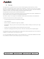
1.
GENERAL DESCRIPTION
The A620 and A621 are versatile Clamshell (Easy paper loading) thermal printers, designed for desktop or portable use.
By following the guide lines in this manual and with careful handling, a long and reliable operating life can be expected from
these printers.
Please note that portable versions that include batteries are provided with unloaded batteries for safety and storage reasons.
1.1.
Main Features
! International character set.
! Automatic power-off features.
! User selectable options stored in non-volatile RAM.
! Automatic power up from data line activity.
! Built-in tab stops.
! Self-test facility.
! Graphics.
! Reset command.
! Diagnostic Mode.
! Emulation Choice : see chapter "Order Code".
! Bar Code Printing.
! User defined character set.
1.2.
SPECIFICATIONS
FEATURE
VALUE / COMMENT
UNIT
Static thermal dot line printing
-
384
-
Resolution
8
Dots/mm
Printing width
48
mm
58 ± 0.1
mm
16 x 24 dots. (24 columns)
or 9 x 24 (40 columns)
-
RS232 Serial.
-
8 minimum
K bytes
Printing Speed
12
character lines / sec*
Height
72
mm
Width
108
mm
Depth
147
mm
Weight
425
611 (With battery)
g
0 to 50
°C
Storage Temperature
-20 to 50
°C
Operating humidity
10 to 85
% RH (Non-Condensing)
Storage humidity
10 to 90
% RH (Non-Condensing)
Electrical Reliability
50
million head pulses per dot
Mechanical Reliability (abrasion
resistance)
50
Km
Printing method
Number of resistor dots
Paper width
Character Fonts
Interface
Buffer
Operating Temperature
* When the number of Dots "ON" is < 30 %. Otherwise the multi-heat mode is activated and 4 heats will be performed. This
mode causes a decreasing printing speed.
A620 & A621
User Manual page 3 / 37
Ref : FDE - 3104471
Issue : B
Battery models :
External, replaceable battery pack, Duracell DR10 or GP VD151.
Text can be printed continuously for approximately 20,000 lines when
the batteries are fully charged.
It will take 14 hours (without printing) to totally charge the battery via
the printer.
As an example after ½ hour charging, the printer can print 1 meter of
paper (270 text lines with the test used).
A power saving feature automatically switches the printer off when the
interface has not been used for a 1 or 5 minute (programmable) period.
A continuous power-on option is available.
Power supplies :
For desktop models, without batteries, a supply of 9 Vdc. is required. The
current rating of the supply will depend on the print duty (More black
print - more current) but typically a 9v supply at 3A will suffice for most
applications.
Emi and Safety
CE mark
FCC class B
C-tick for Australia
UL
cUL / CSA
Vibration
Sinusoïdal vibration tests
The standard used for this test was : IEC68-2-6
5-9 Hz, 6 mm displacement
9-200 Hz, 1g of accélération.
1 octave / minute
12 cycles per axis
3 axes
Printer unpacked and operating
Random vibration tests
The standard used for this test was : IEC 68-2-36
5-200 Hz, DSP : 0.01 g2/Hz
200-500 Hz, DSP : 0.03 g2/Hz.
mean acceleration : 1.7 g
Duration : 30min per axis
3 axes
Printer unpacked and operating
Shake vibration tests
The standard used for this test was : IEC 68-2-29
Wave : half sinusoidal
Acceleration : 15 g
Duration : 6 min
6 axes (±OX, ±OY, ±OZ)
Drop test
A620 & A621
The printer is packed.
1 meter on concrete
1 meter on wood
User Manual page 4 / 37
Ref : FDE - 3104471
Issue : B
1.3.
Order Code
A6 printer is available in many variants.
The table below shows the valid product codes which are used to described each version.
This chapter give the meaning of each digit of the full product name.
It can help you to know the characteristics of your mechanism.
All versions proposed in this chapter are not necessarily available. If you are looking for one of those : once you have
determined your need, contact your sales representative to make sure the needed version is available (or in which
conditions it could be created).
Digits description :
A62 <x2> <x3> <x4< <x5> <x6>
Application
x2 = 0 : Desktop
x2 = 1 : Portable
x2 = 2 : Label
Interface and software configuration
x3 =
Emulation
RS232 Centronics
ESC POS / Citizen 560
0
1
/ Compatible DP 1200
ESC POS second
4
5
receipt management
Verifone P250
A
B
IrDA
2
RF
3
6
7
C
D
Specific fonts
x4 = 0 : Standard Font
x4 = K : Kanji Font
Board configuration
x5 = 0 : Standard board configuration ( Hitachi Microprocessor )
x5 = N : New board configuration ( ST10 microprocessor )
note : There is a different power supply with the new board configuration.
Power supply
x6 = B : With battery
x6 = R : With battery and rubber boot
x6 = 0 : Without power supply
x6 = E : European Power supply
x6 = U : US Power supply
x6 = G : UK Power supply
x6 = J : Japanese Power supply
x6 = A : Australian Power supply
A620 & A621
User Manual page 5 / 37
Ref : FDE - 3104471
Issue : B
1.4.
Warranty
The supplied printers are guaranteed for a period of 12 (twelve) months beginning at the date of delivery (ex-works).
The printers are guaranteed against defective material and/or workmanship. The warranty covers solely, and at Axiohm’s
choice, the cost of repair or replacement by Axiohm in its factory, after restitution by the customer, of the printers admitted by
AXIOHM to be defective, and excluding assembling, dismounting, shipping and other expenses.
The implementation of the warranty will not extend the warranty period.
Due to the complexity of the electronic and mechanical techniques used in the operation of such a printer, AXIOHM does not
warranty particular results for its installation out of the published specifications.
This warranty is subject to strict compliance with AXIOHM’s technical instructions for installation, use and maintenance.
In particular, this warranty will not be valid for any defects due to:
•
Use of thermal papers other than those recommended by AXIOHM
•
Incorrect maintenance
•
Defective installation or modification not approved by AXIOHM
•
Non-compliance, during any period, with the specified working conditions including the electrical power supply
specifications
•
Abnormal wear or mechanical damage, including dot burning due to power overloads
•
transportation in packaging other than the type of carton / foam insert in which the printer was originally shipped
Any transportation, storage or setting up which does not comply with the technical specifications given to the customer by
AXIOHM, or its official distributor, will invalidate this warranty.
In no event shall AXIOHM assume any liability in excess of that defined above. It is agreed that AXIOHM will not be liable
for any indemnity for accidents to persons, damage to property or for loss of earnings.
A620 & A621
User Manual page 6 / 37
Ref : FDE - 3104471
Issue : B
2.
INSTALLATION / SET-UP
2.1.
YOUR PRINTER
2.1.1. Package
The packing box contains :
n Printer
n Power supply for A620 versions (except A6200000) with connecting cables to the printer and
to the power network.
n Battery for A621000B versions (except A6210000)
n Paper roll
n Set Up Guide
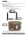
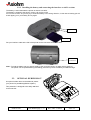
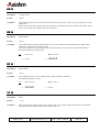
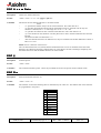
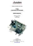
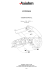
2.1.2. General description
The A620 & A621 are complete printers designed with the clamshell easy paper loading system.
A620 series are desktop printer versions, A621 are portable versions that cannot be used while connected
to a power supply for battery loading.
Opening Cover
Finger recesses to
open cover
Tear bar
for paper
cutting
" Off " button
" on " & Paper feed button
A620 & A621
User Manual page 7 / 37
Ref : FDE - 3104471
Issue : B
2.1.3. Printer location
The printer should be set on a stable holder (for desktop versions) in a place where the following conditions are
achieved :
n temperature from 0 to 50°C for operating (- 20 to 50 for storage)
n no risk of water, grease or dust exposure
n No mechanical stress
n It is recommended to avoid the mechanical vibrations
n When using the power adapter avoid using a mains outlet which also supplies heavy switching machinery
since a noisy supply may impair printer operation.
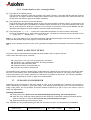
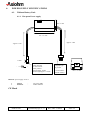
2.2.
PLUGGING & CONNECTING YOUR PRINTER
2.2.1. Connecting the power supply and interface on A620 versions
Approximate
length : 1.8m
Approximate
length : 1.8m
To be connected to the printer
-
To be connected to the
power network. The
connector type depends
on the country.
+
Connect the interface
cable with the DB25
connector
Note : When using versions provided without power supply, please ensure that the adapter provides the
correct operating voltage and current (see chapter "Power Supply Specifications").
A620 & A621
User Manual page 8 / 37
Ref : FDE - 3104471
Issue : B
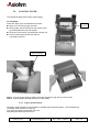
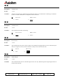
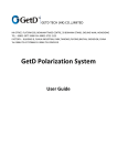
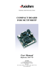
2.2.2. Installing the battery and connecting the interface on A621 versions
The battery is set underneath the printer as shown here after.
The battery is clipped to the printer, push to clip, pull to unclip.
Do not force to much as you may try to insert the battery in the wrong direction, in this case a locating pin will
avoid clipping, turn your battery and try again.
contacts
set & clip
Set your interface cable at the rear of the printer to the connector shown here after.
interface
connection
Note : To load the battery set your power supply to the connector shown on A620 version (page 4)
The printer can be operated during the loading process only when the battery is loaded enough.
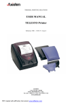
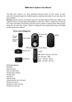
2.3.
OPTIONAL RUBER BOO T
An optional rubber boot can be added to protect
your printer for portable applications (A621).
This protection is designed to be easily attached
to the user belt.
A620 & A621
User Manual page 9 / 37
Ref : FDE - 3104471
Issue : B
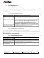
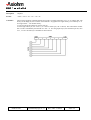
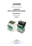
2.4.
LOADING PAPER
The Clamshell design allows easy paper loading.
To load paper :
Roll setting
indications
Follow the steps given and illustrated here after :
n Open the cover using finger recesses.
n Set the paper roll as indicated on the picture below
by pushing aside the right roll support.
n Close the cover leaving a small length of paper out.
n Cut the small length left with the tear bar.
Your paper roll is set.
right roll support
Note 1 : Do not remove paper by pulling excessive lengths through the top of the printer.
Note 2 : PAPER MUST NOT BE STUCK TO THE CORE
2.4.1. Paper Specifications
The paper used should be recommended by AXIOHM (Recommended paper : JUJO AF50KS-E3)
The paper width must be 57 to 58 mm
The maximum paper roll diameter is 55 mm
Standard paper thickness 65 microns
A620 & A621
User Manual page 10 / 37
Ref : FDE - 3104471
Issue : B
2.5.
TROUBLESHOOTING
2.5.1. Light indicators on A620 (desktop)
When the printer is powered the "off " button is lighted (colour red), the printer is in stand-by mode.
When the printer is set "on", the "on" button is lighted (colour green), the "off" button is still lighted, the printer can
receive data and print.
2.5.2. Problems & Solutions on A620
Lights are "off " when powered
Check the power supply and cables connections.
Lights are continuously "on " but
printer does not operate
Check to see if the interface cable is well connected.
The green light is flashing
Check that cover is well closed, if not close it.
Open the cover and make sure there is paper left in the printer, if not :
remove the paper roll core, place a new paper roll.
Open the cover and check there is no paper jam, if there is some :
unwind the paper untill no wrinkle appears, close the cover with wrinkled
part out and cut it with the tear bar.
Printing quality is deteriorating
The printhead may be getting dirty, see next chapter.
2.5.3. Light indicators on A621 (portable)
When the printer is powered by installing the battery, none of the button is lighted.
When the printer is set "on", the "on" button is lighted (colour green), the "off" button is not lighted, the printer can
receive data and print.
When loading the battery, the "off" button (colour red) is lighted. In this case the printer can be used only if the
battery is loaded enough as previously mentioned.
2.5.4. Problems & Solutions on A621
The green light is continuously
"on " but printer does not operate
Check to see if the interface cable is well connected.
The green light is flashing
Same solution as for A620 version described above
Printing quality is deteriorating
The printhead may be getting dirty, see next chapter.
Very low printing speed and very
low printing density.
The battery needs to be re-powered.
A620 & A621
User Manual page 11 / 37
Ref : FDE - 3104471
Issue : B
2.5.5. Further details to solve eventual problems
(1) The paper is not feeding properly.
If the print looks squashed, check that the paper roll is sitting correctly in the paper well and that the roll is the
right way up. The paper should be feeding off the bottom of the roll into the back of the mechanism NOT off
the top of the roll. Remove paper and reload if necessary.
(2) The printer does not switch on from the data line.
If the printer does not automatically switch on when the communications channel is active, check that the host
is able to send data and the handshaking is disabled. When the printer is off, most host equipment will not be
able to send data as the DTR line is inactive. For the switch on procedure, DTR must be disabled, the NUL
characters transmitted, then DTR enabled to resume normal communications.
(3) The printer prints “ ?” “ !” or “ *” in place of the transmitted characters or it does not action commands.
Check the handshaking line, parity setting and baud-rate. The different characters denote particular errors:
“ ?” - parity error, “ !” - framing error, “ *” - over run error.
Note 1 : in any case make sure you use thermal sensitive paper and that the paper roll is well set in its bucket.
Check that the sensitive layer of the paper is on the print-head side
Note 2 : when resetting the printer, every running operation is stopped and all information sent before resetting are
lost.
2.6.
PRINT A SELF TEST TICKET
The printer must be powered and some paper must be loaded in order to get the self test.
Follow next instructions to print a self test :
n
n
n
n
n
If the printer is "on" set it "off" by pushing the "off" button.
activate the ("on" & paper feed) button and keep it pressed.
wait for the self test ticket to start
release the button, the self test will run
press the "off" button to stop the test
The software issue is printed in double height, double width text, followed by the character set in normal text and a
list of the current settings of the user selectable options. If the settings are correct for your host you are ready to
connect the printer to your system, otherwise you will need to re-programme the printer. The self test is repeated
until the power is switched off. Power on again for normal operation.
2.7.
CLEANING YOUR PRINTER
Depending on the environment in which the printer is used, it can accumulate dust. Therefore it is necessary to
clean it periodically to maintain a good print quality. The cleaning period depends on the environment and the
usage of the printer, but the printhead should be cleaned at least once a year or up to one month in case of
heavy duty applications.
Cleaning Instructions :
n Unplug the printer. Never clean the head immediately after printing, the head may be hot.
n Open the cover, clean the heating dots line of the head with a cotton stick containing a solvent alcohol
(ethanol, methanol, or IPA) but do not touch the printhead with your fingers !
n Allow the solvent to dry and close the cover.
N.B : AXIOHM can also provide cleaning kits with the instructions to use it. The kit reference is CK60000A.
A620 & A621
User Manual page 12 / 37
Ref : FDE - 3104471
Issue : B
3.
FUNCTION DESCRIPTION FOR PRINTER DRIVING
3.1.
Default Settings
A620
A621
Data bits 8
Parity None
Baud Rate 9600
Country USA
Print Mode Text
Auto-Off Disabled
Emulation Standard ( Compatible DP1000 / DP1200 )
DTR Normal
Chars/Line 24
Graphics Standard
Contrast 2
Label Disabled ( Does not exist yet )
Data bits 8
Parity None
Baud Rate 9600
Country USA
Print Mode Text
Auto-Off 5 minutes
Emulation Standard ( Compatible DP1000 / DP1200 )
DTR Normal
Chars/Line 24
Graphics Standard
Contrast 2
Label Disabled ( Does not exist yet )
Default settings can be restored by pressing both the feed and programme switches together at power up. Releasing
the feed button before the programme button will set original defaults*.
* " Default restored" should be printed on the paper.
3.2.
Interface Connections
The A620 printers are available as standard with RS232 Serial interface.
The interface type is printed on the self-test slip.
The connector is a 25 way D socket for desktop model.
The connector is a Binder 5 for portable model.
A620
Function
RX
TX
CTS
DTR
GND
NC
FG
RTS
A620 & A621
A621
( 25 Way D Socket )
Connector Pinout Input/Output
3
2
5
20
7
6,8-19,21-25
1
4 (+10V via 1K)
IN
OUT
IN
OUT
OUT
User Manual page 13 / 37
Function
( Binder )
Connector Pinout
Input/Output
RX
TX
CTS
DTR
GND
NC
FG
RTS
3
2
5
4
1
-
IN
OUT
IN
OUT
OUT
Ref : FDE - 3104471
Issue : B
3.2.1. PC → Board Connections
A620
25 Way D Socket
→
Pins :
3
2
5
20
7
→
→
→
→
→
PC
3 ( TX )
2 ( RX )
4 ( DTR )
6 ( DSR )
5 ( GND )
Pins :
A621
Binder
→
PC
3
2
5
4
1
→
→
→
→
→
3
2
4
6
5
Ref. 09-9792-30-05-5
3.2.2. Serial interface timing
MARK = - 10 V
SPACE = + 10 V
N.B. :
DTR WILL BE SET FOR A MINIMUM OF 70 µs AT THE END OF THE STOP BIT ON EACH CHARACTER.
THIS CONDITION WILL BE LONGER FOR BUFFER FULL AND WILL BE SET UNTIL RESET IF A PRINTER
FAULT OCCURS.
3.3.
Program Mode
The program switch may be accessed through a small hole on the side of the printer. This can be pressed using a
small pin eg a paper clip
3.3.1. How to enter the program mode
To enter the program mode, press the program switch and the paper feed button together and then release the paper feed
button. The program mode starts automatically.
3.3.2. How to move in the program
If you want to validate a parameter, press the paper feed button ; in the other case, if you want to make another selection,
press the switch program button.
A620 & A621
User Manual page 14 / 37
Ref : FDE - 3104471
Issue : B
3.3.3. how to quit and save the program
When all the necessary changes to the parameters have been made, press the programme and the feed switch together
to update the status of the printer. If no switches are pressed for 15 seconds the set-up mode is terminated without
changing the original parameters.
Parameter (FEED Switch)
Status (PROGRAMME Switch)
(1) Number of data bits
8 bit data ** (** Default Settings)
7 bit data
(2) * Parity
No parity **
Odd parity
Even parity
(3) * Baud Rate
300 baud
600 baud
1200 baud
2400 baud
4800 baud
9600 baud **
19200 baud
* NB: Not printed for a parallel interface
(4) Country
USA **
FRANCE
GERMANY
UK
DENMARK 1
SWEDEN
(5) Print Mode
TEXT (Normal Print)
DATA (Inverted Print)
(6) Auto POWER OFF
5 minutes **
1 minute
Disabled
(7) Emulation
DP1000 / DP1200 **
Compatible Citizen 560
ESC/POS
(8) DTR
Normal **
Inverted
(9) Characters/Line
24 **
40
(10) Graphics
Standard **
Compatible Epson
High resolution graphics
(11) Contrast
1-10
A620 & A621
User Manual page 15 / 37
1 is lightest
10 is darkest
Ref : FDE - 3104471
ITALY
SPAIN
JAPAN
NORWAY
DENMARK 2
(2 Default)
Issue : B
3.4.
Automatic Switch On ( A621 ONLY )
As a standard mode of operation, the A621 will “wake-up” in response to activity on the data line. To use this power
saving facility, the DTR handshaking must be disabled whilst a string of approximately 95 NUL characters (00H)
are sent to the printer. This allows time for the logic to reset and initialise the printer correctly. Any NUL characters
that are received as valid data from this string will be discarded as non-printable data. Once the start up sequence is
complete, reactivate the DTR handshaking so that normal communications can be resumed.
Basic program example :
OPEN "COM1:9600,n,8,1,RS,DS0,CS0" FOR OUTPUT AS #1
FOR CHAR = 1 TO 95
PRINT #1, CHR$(0);
NEXT CHAR
CLOSE
OPEN "COM1:9600,n,8,1,RS,DS0,CS0" FOR OUTPUT AS #1
PRINT #1, "A621 Woke up with succes"
When used in combination with the auto-off feature, the printer can effectively be switched on when required to print,
thus extracting maximum capacity from the battery pack.
A620 & A621
User Manual page 16 / 37
Ref : FDE - 3104471
Issue : B
4.
PROGRAMMING
4.1.
Command Summary for the A620 Printer
Function
Keystroke
Hex
Decimal
Command Summary For Emulation compatible with DP1000 and DP1200
Horizontal Tab
Line Feed
Form/Label Feed
Vertical Tab
Carriage Return
Double Width
Single Width
Reset
Underline
Underline Release
Reverse Print
Double Height
Standard Graphics
Epson Graphics
24 Column
40 Column
CTRL I
CTRL J
CTRL K
CTRL L, n
CTRL M
CTRL N
CTRL O
CTRL Q
CTRL U
CTRL X
CTRL Y
CTRL Z
CTRL [, n
CTRL [,K,n1,n2
CTRL\
CTRL]
09H
0AH
0BH
0CH, n
0DH
0EH
0FH
11H
15H
18H
19H
1AH
1BH, n
1BH,4BH,n1,n2
1CH
1DH
9
10
11
12,n
13
14
15
17
21
24
25
26
27,n
27,75,n1,n2
28
29
0AH
0CH
0DH
0EH
0FH
14H
18H
1BH, 4BH
1BH, 43H*
1BH, 4FH*
1BH, 31H*
1BH, 32H*
1EH
1FH
10
12
13
14
15
20
24
27,75
27,67 *Commands
27,79 acknowledged
27,49 but not
27,50 executed
30
31
Command Summary For Emulation compatible with Citizen 560
Line Feed
Form Feed
Carriage Return
Shift Out
Shift In
Reverse Print
Clear Buffer
Graphic Print
Page length/format
Paging Is Off
2.75 mm Spacing
5.5 mm Spacing
Double Width
Single Width
A620 & A621
CTRL J
CTRL L
CTRL M
CTRL N
CTRL O
CTRL T
CTRL X
ESC K
ESC C
ESC O
ESC 1
ESC 2
-
User Manual page 17 / 37
Ref : FDE - 3104471
Issue : B
Command Summary For ESC/POS Emulation (compatible with Epson)
Horizontal Tab
Line Feed
Form Feed
Carriage Return
Set Print Mode
Set print position
Set cancel UDC
User Defined Character
Bit image graphics
Initialise Printer
Set form length
Character Set
Print & Feed
Status Request
Inverted Printing
HRI print position
HRI character font
Bar code height
Print bar code
Bar code magnification
A620 & A621
CTRL I
CTRL J
CTRL L
CTRL M
ESC !,n
ESC $ n1,n2
ESC %,n
ESC & s,n,m,
[a[p]sxa]m-n+1
ESC*m,n1,n2
ESC @
ESC C,n
ESC R,n
ESC d,n
ESC v
ESC {,n
GS,H,n
GS,f,n
GS,h n
GS k n,d,m,NUL
GS w,n
09H
0AH
0CH
0DH
1BH, 21H, n
1BH, 24H, n1,n2
1BH, 25H, n
1BH, 26H, s,n,m,
[a[p]sxa]m-n+1
1BH, 2AH,m,n1,n2
1BH, 40H
1BH, 43H, n
1BH, 52H, n
1BH, 64H, n
1BH, 76H
1BH, 7BH, n
1DH, 48H, n
1DH, 66H, n
1DH, 68H, n
1DH, 6BH, n,d,m,0H
1DH, 77H, n
User Manual page 18 / 37
9
10
12
13
27,33,n
27,36,n1,n2
27,37,n
27, 38,s,n,m,
[a[p]sxa]m-n+1
27,42,m,n1,n2
27,64
27,67,n
27,82,n
27,100,n
27,118
27,123,n
29,72,n
29,102,n
29,104,n
29,107,n,d,m,0
29,119,n
Ref : FDE - 3104471
Issue : B
4.2.
Command Description for the A620 Printer
09 H
Description
Horizontal tab.
Format
<09 h>
Comments
This command moves the printing position to the next horizontal tab position.
Tab stops occur at every 8th column. On receipt of this command, spaces are entered into the line up to the
next tab stop.
Ex :
09 41 41 41 41 41 41 41 41 41
⇒ _ _ _ _ _ _ _ _AAAAAAAAA
LF
Description
Feed one line.
Format
<0A h>
Comments
This command prints and moves the printing position to the beginning of the next line.
If LF and CR are sent, the CR is ignored to avoid a double feed.
Ex :
41 41 41 41 41 0A 41 41 41
⇒ AAAAA
AAA
0B H
Description
Form feed.
Format
<0A h>
Comments
This command Will feed 5 fast line feeds in normal mode or will feed to top of label registration mark in
label mode.
0C H n
Description
Vertical Tab.
Format
<0C h> <n>
Comments
This command fast feeds the paper by n lines where n is a single byte hex number in the range 0 < n < 63.
Note that a vertical tab will print the contents of the line buffer before being executed.
A620 & A621
User Manual page 19 / 37
Ref : FDE - 3104471
Issue : B
0D H
Description
Carriage return.
Format
<0D h>
Comments
This command prints the current line and feeds one line. If CR and LF are sent, the LF is ignored to avoid a
double feed.
On the receipt of the last printable character, the printer will automatically print the data in the buffer. If CR
and LF are sent after this condition, they will be ignored.
0E H
Description
Double width.
Format
<0E h>
Comments
This command Turns double width printing on. This state continues until terminated by the single width
command or completion of the current line.
If the last character in the line buffer is double width but there is only room for a single width character,
then it will be printed in single width.
Ex :
41 41 41 41
⇒ AAAA
0E 41 41 41 41
⇒
AAAA
0F H
Description
Single width.
Format
<0F h>
Comments
This command reverts to single width printing. Single and double width can
be combined anywhere on a line.
Ex :
⇒
0E 41 41 41 41
AAAA
0F 41 41 41 41
⇒ AAAA
11 H
Description
Reset.
Format
<11 h>
Comments
This command causes printer status reset. Printer status is set to single width, normal height, no underline.
Note that the buffer remains unaltered to avoid any data loss.
A620 & A621
User Manual page 20 / 37
Ref : FDE - 3104471
Issue : B
15 H
Description
Underline ON.
Format
<15 h>
Comments
Characters sent after this command will be underlined. Tabs are not underlined. Underlining is terminated
by the U/L release command or on completion of the current line.
Ex :
41 41 41 41
15 41 41 41 41
⇒ AAAA
⇒ AAAA
18 H
Description
Underline OFF.
Format
<18 h>
Comments
This command Terminates underlining.
Ex :
15 41 41 41 41
18 41 41 41 41
⇒ AAAA
⇒ AAAA
19 H
Description
Reverse Print.
Format
<19 h>
Comments
This command sets the print to white on black. The command will toggle between reverse and normal print
wherever it appears on a line, but the condition is always reset at the end of the line.
Ex :
⇒
41 41 41
AAA
19 41 41 41
⇒
AAA
1A H
Description
Double Height.
Format
<1A h>
Comments
This command Prints the line in double height for one line only. Double height and single height cannot be
mixed on the same line.
A620 & A621
User Manual page 21 / 37
Ref : FDE - 3104471
Issue : B
1B H n
Description
Standard graphics.
Format
<1B h> <n>
Comments
Standard 1000 Emulation
Graphics command to enter bit image printing. The number of graphic bytes sent will depend on the column
selection ie 24 or 40. For each graphic byte sent, 6 bits out of the 8 bits are used to build the graphics string
(LSB as the right most dot) and 'n' is the number of times the string will be repeated for a repetitive pattern.
The value of 'n' is limited to a maximum of 255 lines. The print buffer will be printed first if not empty.
Examples:
To repeat a string of data bytes, d1....d24 over two rows for 24 column printing send : 1BH, 02H, d1....d24.
For a non-repeated string send : 1BH, 01H, d1....d24.
High Resolution Graphics
To make use of the higher resolution on the DP1200 that is not available on the 1000, there is an option in
the set up for changing the default graphics. This works in the same manner as the standard emulation but
there are 48 characters across the line, rather than 24 or 40. This provides full dot addressable graphics at 8
dots/mm and a true image of the data received.
1C H
Description
24 Columns Font.
Format
<1B h>
Comments
This command selects 24 column font. ie Sets 24 characters per line printing.
1D H
Description
40 Columns Font.
Format
<1D h>
Comments
This command selects 40 column font. ie Sets 40 characters per line printing.
ESC K n1 n2
Description
Graphics compatible with Epson.
Format
<1B h> <4B h> <n1> <n2>
Comments
This command Made possible by the higher resolution and memory capability of the DP1200 over the
standard 1000. The number of graphic bytes is determined by n1 (low order byte) and n2 (high order byte).
For maximum graphics resolution of 384 printable positions, n1=128 and n2=1 (representing 256). For 200
graphic bytes, n1=200, n2=0. That is 0<n1<255, 0<n2<1.
Each data character represents 8 dot rows of graphics, the LSB being the lowest dot.
The command and data must be sent for each line of graphics.
A620 & A621
User Manual page 22 / 37
Ref : FDE - 3104471
Issue : B
4.3.
ESC/POS Command Description
09 H
Description
Horizontal tab.
Format
<09 h>
Comments
This command moves the printing position to the next horizontal tab position.
Tab stops occur at every 8th column. On receipt of this command, spaces are entered into the line up to the
next tab stop.
Ex :
09 41 41 41 41 41 41 41 41 41
⇒ _ _ _ _ _ _ _ _AAAAAAAAA
LF
Description
Feed one line.
Format
<0A h>
Comments
This command prints and moves the printing position to the beginning of the next line.
If LF and CR are sent, the CR is ignored to avoid a double feed.
Ex :
41 41 41 41 41 0A 41 41 41
⇒ AAAAA
AAA
0C H
Description
Form Feed.
Format
<0C h>
Comments
This command prints the current line and feeds the number of lines determined by using the ESC C
command..
0D H
Description
Form Feed.
Format
<0D h>
Comments
This command prints the current line and feeds one line. If CR and LF are sent, the LF is ignored to avoid a
double feed.
A620 & A621
User Manual page 23 / 37
Ref : FDE - 3104471
Issue : B
ESC ! n
Description
Set print mode.
Format
<1B h> <21 h> <n>
Comments
This command sets the print mode according to the following table and n is a single byte in which each bit
sets the printing function. Note that underlines cannot be used with a horizontal tab and any combination of
double height and width can be used. Double and single height cannot be mixed on a line, however, whereas
double and single width can be mixed anywhere on a line.
Default is n = 0.
Value
Bit
0
1
2
3
4
5
6
7
Function
Character Font
Undefined
Undefined
Undefined
Double-height
Double-width
Undefined
Underline
0
16 x 24
Cancelled
Cancelled
Cancelled
1
9 x 24
Set
Set
Set
ESC % n
Description
Set / Cancel user defined character set.
Format
<1B h> <25 h> <n>
Comments
The range of n is 0 < n < 255. This sets or cancels the user defined character set.
Note: Once the user defined character set has been cancelled the default character set will be loaded and the
user defined characters will be lost.
A620 & A621
User Manual page 24 / 37
Ref : FDE - 3104471
Issue : B
ESC & s n m Data
Description
Define user defined characters.
Format
<1B h> <26 h> <s> <n> <m> [a[p] s x a]m-n+1
Comments
This allows the user-defined characters to be down-loaded:
where:
"s" specifies the number of bytes in the vertical direction. This value must be 3.
"n" specifies the beginning ASCII code for the definition and "m" the final code. If only one
character is defined, use n = m. The range for n is 32 < n < m < 255.
"a" specifies the number of dots in the horizontal direction. This value must be 16.
"p" is the dot data for the characters. The dot pattern for a dots in the horizontal direction from the
left side.
The amount of data to be defined is s x a.
After user-defined characters are defined once, they are available until another definition is made or
ESC % n is sent.
NOTE: See Ch "character cell structure".
The User defined character set (UDCS) and the standard character set are not available at the same time.
Normally, the UDCS will be battery backed. However, if the batteries are left to discharge completely, then
the UDCS will be lost and the default character set will be loaded.
ESC @
Description
Initialise printer.
Format
<1B h> <40 h>
Comments
This command initialise printer. Clears the print buffer and resets the printer mode to default values.
ESC R n
Description
Select International character set.
Format
<1B h> <52 h> <n>
Comments
The character set from the following table is determined by the value of n. The default value is the character
set programmed in the printer.
n
0
1
2
3
4
5
6
7
8
9
10
A620 & A621
Country
U.S.A.
France
Germany
U.K.
Denmark 1
Sweden
Italy
Spain
Japan
Norway
Denmark 2
User Manual page 25 / 37
Ref : FDE - 3104471
Issue : B
ESC d n
Description
Print and feed.
Format
<1B h> <64 h> <n>
Comments
This command prints the data in the print buffer and performs n line feeds.
ESC v
Description
Status request.
Format
<1B h> <76 h>
Comments
The current printer status is transmitted to the host computer on receipt of this command. It takes the form
of a single byte with each bit representing a specific printer condition. The conditions indicated are “true”
when the bit is a logic “1".
Bit 0
1
2
3
4
5
6
7
Paper out
Feeding paper
Lid open
Low voltage
Always zero
Not used
Not used
Buffer full
The byte is sent regardless of the CTS handshaking signal.
ESC { n
Description
Inverted print.
Format
<1B h> <7B h> <n>
Comments
When n = 1 then print is inverted and text will be printed from right to left. For normal print n = 0. The
default mode is set by the programmed parameters in the printer.
ESC C n
Description
Set form lenght.
Format
<1B h> <43 h> <n>
Comments
When used in conjunction with the form feed command (0CH), the printer will feed n lines. Note that if n =
0 then there will be no line feeds. The default value is n = 0.
A620 & A621
User Manual page 26 / 37
Ref : FDE - 3104471
Issue : B
ESC $ n1 n2
Description
Print starting position.
Format
<1B h> <24 h> <n1> <n2>
Comments
This command sets the print starting position to the specified number of dots from the margin. The range is
from 0 to 384 where n2 is the high order byte (0˜n2 ˜1) and n1 is the low order byte (0˜n1˜255). The default
condition is n1=n2=0 which positions print on the left margin. The print position will always be rounded
down to the nearest multiple of 8. (eg Print position 45 will be rounded down to 40.)
GS k n d m Nul
Description
Bar codes / Set bar code types.
Format
<1D h> <6B h> <n> <d> <m> <00 h>
Comments
The print bar code command selects a bar code, formats the data and prints the bar code according to the
variables n, d and m. The type of bar code is defined by “n” and valid values are displayed in the table
below.
n
0
1
2
3
4
5
6
7
Bar code types
UPC-A
UPC-E
EAN13
EAN8
CODE39
ITF
NOT ASSIGNED
CODE128
d is the string of characters to be printed as the bar code.
m specifies the number of characters sent. This must be sent for code128 bar codes but is optional for the
others.
This command will always set the print position to that specified by the ESC $ (print position) command.
Certain error conditions result in data being ignored and nothing being printed, these conditions are:
-
invalid bar code type
invalid characters (d) in bar code
too many/few characters sent (UPC and EAN bar codes)
number of characters sent is not equal to m
bar code is wider than paper
Check characters can be sent but are overwritten by the calculated check character and are therefore
redundant.
A620 & A621
User Manual page 27 / 37
Ref : FDE - 3104471
Issue : B
GS w n
Description
Set bar code magnification.
Format
<1D h> <77 h> <n>
Comments
This command selects magnification (horizontal size) of the bar code. The range is 2< n<4. The default
value is n=3.
GS h n
Description
Set bar code height.
Format
<1D h> <68 h> <n>
Comments
The range is 1<n<255 and n specifies the number of dots in the bar code height. Default value is n=162.
Note that if n=0, the default height is used.
GS H n
Description
Set HRI print position.
Format
<1D h> <48 h> <n>
Comments
The range is 0<n<3. The default value is n=0 and ”n” defines the print position as follows:
n=0 not printed
n=1 above the bar code
n=2 below the bar code
n=3 above and below the bar code
Guard patterns are not printed in the HRI text.
GS f n
Description
Select HRI font.
Format
<1D h> <66 h> <n>
Comments
The range is n=0 or 1 (default 0). If n=0, the 24 column font is selected.
If n=1, the 40 column font is selected.
A620 & A621
User Manual page 28 / 37
Ref : FDE - 3104471
Issue : B
ESC * m n1 n2 d
Description
Graphics.
Format
<1B h> <2A h> <m> <n1> <n2> <d>
Comments
The bit image graphics command formats and prints a bit image depending on m, n1, n2 and the data. The
density of bit image (m) has no effect on the DP1200. All graphics are single density, but ordinarily m = 0
for single and m = 1 for double density.
n1, and n2 specify the number of of bytes sent (d).
n2 is the high order byte ( 0 £ n2 £ 1 ), n1 is the low order byte ( 0 £ n1 £ 255). The total number of data
bits to send is calculated by the formula n2 x 256 + n1. For 384 graphic bytes, the maximum per line, then
n2=1, n1=128. The data (d) is formatted as shown below.
A620 & A621
User Manual page 29 / 37
Ref : FDE - 3104471
Issue : B
4.4.
Command Description for the A620 Printer with Emulation compatible with
Citizen 560
0A H
Description
Line feed
Format
<0A h>
Comments
This command prints the current line and feeds one line. If LF and CR are sent, the CR is ignored to avoid a
double feed.
0C H
Description
Form feed
Format
<0C h>
Comments
This command will feed 4 fast line feeds.
0D H
Description
Carriage return
Format
<0D h>
Comments
This command prints the current line and feeds one line. If CR and LF are sent, the LF is ignored to avoid a
double feed.
On the receipt of the last printable character (eg 24th, if characters per line is set to 24) the printer will
automatically print the data in the buffer. If CR and LF are sent after this condition, they will be ignored.
0E H
Description
Shift OUT
Format
<0E h>
Comments
This command access upper half of character set if 7 data bits selected. If 8 data bits selected, then turn
DOUBLE WIDTH printing on.
0F H
Description
Shift IN
Format
<0E h>
Comments
This command access lower half of character set if 7 data bits selected. If 8 data bits selected, then turn
SINGLE WIDTH printing on.
A620 & A621
User Manual page 30 / 37
Ref : FDE - 3104471
Issue : B
14 H
Description
Reverse print
Format
<14 h>
Comments
This command sets the print to white on black. The command will toggle between reverse and normal print
wherever it appears on a line but the condition is always reset at the end of the line.
18 H
Description
Clear buffer
Format
<18 h>
Comments
This command clears the print data in the buffer. All the previous input data is cleared with this code.
However, in case of graphic print mode, this code is treated as data.
1E H
Description
Double width
Format
<1E h>
Comments
This command turns double width printing on. This state continues until terminated by the single width
command or completion of the current line.
If the last character in the line buffer is double width, but there is only room for a single width character,
then it will be printed in single width.
1F H
Description
Single width
Format
<1F h>
Comments
This command reverts to single width printing. Single and double width can be combined anywhere on a
line.
ESC K n1 n2 H
Description
Graphics command ( Compatible with Citizen 560 )
Format
<1B h> <4B h> <n1> <n2>
Comments
This command requires special note because all associated data will be ignored. The number of graphics
bytes determined by n1 and n2, will be received but discarded so as not to appear as erroneous text. Note that
n1 can only be up to 240 and n2 will be read as zero as the 560 only allows printing of 240 graphics bytes. If
more than 240 graphics characters are sent, then the balance will be interpreted as non-graphic data.
A620 & A621
User Manual page 31 / 37
Ref : FDE - 3104471
Issue : B
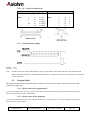
5.
STANDARD AND INTERNATIONAL CHARACTER SET
5.1.
0
0
1
2
3
4
5
6
7
8
9
A
B
C
D
E
F
Standard
1
DC4
CAN
LF
ESC
FF
CR
SO
2
SP
!
"
#
$
%
&
'
(
)
*
+
,
.
/
3
0
1
2
3
4
5
6
7
8
9
:
;
<
=
>
?
4
@
A
B
C
D
E
F
G
H
I
J
K
L
M
N
O
5
P
Q
R
S
T
U
V
W
X
Y
Z
[
\
]
^
_
6
`
a
b
c
d
e
f
g
h
i
j
k
l
m
n
o
7
p
q
r
s
t
u
v
w
x
y
z
{
|
}
~
◊
8
Ç
ü
é
â
ä
à
å
ç
ê
ë
è
ï
î
ì
Ä
Å
9
É
æ
Æ
ô
ö
ò
û
ù
ÿ
Ö
Ü
¢
£
¥
.
ƒ
A
á
í
ó
ú
ñ
Ñ
o
°
¿
¬
¬
½
¼
¡
«
»
B
!
"
#
*
l
|
M
D
@
<
C
.
N
+
$
(
%
'
&
E
α
β
Γ
π
Σ
σ
µ
τ
Φ
Θ
Ω
δ
∞
φ
∈
∩
124D
7CH
|
ù
ö
|
ø
ö
ò
ñ
|
ø
ø
125D
7DH
}
è
ü
}
å
å
è
}
}
å
å
126D
7EH
~
"
ß
~
~
ü
i
~
~
ü
ü
2
0
/
)
3
G
K
9
6
5
7
8
E
A
>
,
123D
7BH
{
é
ä
{
æ
ä
ä
"
{
æ
æ
=
;
:
4
D
J
L
H
F
B
?
C
O
P
SP indicates a space character. Blank locations indicate unused codes.
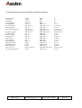
5.2.
International
n
U.S.A.
France
Germany
U.K.
Denmark 1
Sweden
Italy
Spain
Japan
Norway
Denmark 2
A620 & A621
0
1
2
3
4
5
6
7
8
9
10
35D
23H
#
#
#
£
#
#
#
.
#
#
#
36D
24H
$
$
$
$
$
¤
$
$
$
¤
$
64D
40H
@
à
§
@
@
‹
@
@
@
‹
‹
91D
5BH
[
°
ƒ
[
Æ
Ä
°
i
[
Æ
Æ
92D
5CH
\
ç
Ö
\
Ø
Ö
\
Ñ
¥
Ø
Ø
User Manual page 32 / 37
93D
5DH
]
§
Ü
]
Å
Å
é
¿
]
Å
Å
94D
5EH
^
^
^
^
^
Ü
^
^
^
Ü
Ü
96D
60H
`
`
`
`
`
é
ù
`
`
é
é
Ref : FDE - 3104471
Issue : B
F
≡
±
≥
≤
⌠
⌡
÷
≈
°
•
.
√
6
²
#
SP
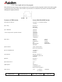
6.
POWER SUPPLY SPECIFICATIONS
6.1.
Without Battery Pack
6.1.1. European Power supply
62+/-1 mm
107 +/-1 mm
Approx. 1.8m
Approx. 1.8m
11mm
-
+
DC-Jack Female connector –
5.5mm external
2.5 mm internal
Centre positive.
Overall length 50mm
Barrell length approx. 11mm.
sector connector*
European type
no ground
* in accordance
with the country
78.8 +/-1 mm
Remark : power supply 23.4VA
•
•
INPUT
OUTPUT
:
:
230 VAC 50Hz
9VDC 2600mA
CE Mark
A620 & A621
User Manual page 33 / 37
Ref : FDE - 3104471
Issue : B
6.1.2. US Power Supply
Remark : power supply 27 VA
•
•
INPUT
OUTPUT
:
:
120 VAC 60Hz 45 w
9VDC 3000mA
MARQUAGE UL, CSA
6.1.3. UK Power supply
The Power supply is the same than the European one. Only the power sector cable changes with a different connector.
sector connector
UK type
with ground
A620 & A621
User Manual page 34 / 37
Ref : FDE - 3104471
Issue : B
6.2.
With Battery Pack
6.2.1. Duracell DR10 Specifications
Nickel-Metal Hybride Rechargeables.
Nominal Voltage
Rated Capacity
Average Weight
Maximum Volume
Terminals
Operating Temperature Range
6.0 V
1800 mAh at C/5 to 5.0 V
21 °C ( 70°F )
182 g ( 6.4 oz.)
78 cm3 ( 4.8 in.3 )
Flat
-20 °C to +50 °C
(-4 °F to 122 °F )
CHARGING
Optimum dischargeable capacity may be achieved using a three stage charge regime :
Rate
C
Followed by
C/10
Followed by
C/300
Current (mA)
1800
Purpose
Main charge
Termination
dT/dt = 1°C/min
Temperature range
10°C to 45°C
150
Top-up charge
Timed 0.5 hour
0°C to 45°C
5
Charge maintenance
None required
-20°C to 50°C
6.2.2. Gold Peak GP VD151 specifications
Model N°
Battery type
For use with
Color
Nominal voltage
Cut off voltage
Capacity
Continuous operating time*
Temperature range
VD 151
Nickel Metal Hybride
Sony NP-55/66/77
Black
6.0 V
5.0 V
1700 mAh at 0.2 °C **
45 Minutes ( estimated )
Charge : 0 – 45 °C
Discharge : -20 – 50 °C
Storage : -20 – 50 °C
Casing material
ABS
Typical weight
165 g
Charging
Battery should be charged in a GP or an original
Manufacturer charger
First charge rate
: 0.1 °C
Subsequent charge rate : 0.1 °C – 1°C
Safety
Each battery is equipped with a thermostat and thermistor to
protect battery from high temperature or short circuit. Each
cell is also equipped with a safety event system in case abuses
occur.
Warranty
6 months limited warranty from data of purchases.
* data valid only when the battery pack is on fully charged condition
** Battery pack should be firstly charged and discharged for 3 complete cycles as a warm-up.
The pack should then be charged at 0.1 °C and it's capacity be measured by discharging at 0.2 °C.
A620 & A621
User Manual page 35 / 37
Ref : FDE - 3104471
Issue : B
7.
BARCODES SPECIFICATIONS
UPC-A, UPC-E, EAN13 and EAN8
These bar code types only accept numeric characters and require a specified number of characters.
UPC-A, 12 (including check character)
UPC-E, 6 (no check character)
EAN13, 13 (including check character)
EAN8, 8 (including check character)
The bar code has right and left guard patterns which are automatically generated. UPC-A and EAN13 are split into two
halves with an automatically generated centre guard pattern. It is not necessary to send a check character as this is
automatically calculated.
CODE39
This bar code type will accept any uppercase alphanumeric characters plus - . * $ / + % and the space character. Code39 uses
start and stop characters which are * characters and are automatically inserted.
ITF
ITF accepts only numeric characters which are encoded in pairs. If an odd number of characters are received, a 0 is inserted at
the start of the bar code. Start and stop characters are inserted automatically.
CODE128
Subsets A, B and C are supported. Subset A includes all uppercase alphanumeric characters and control codes, subset B
includes all alphanumeric characters and subset C uses digit pairs.
Start and stop patterns are generated by the printer and the subset is selected automatically unless forced into a particular set.
The check character is generated automatically. For those characters that are non-printable and therefore not normally
accessible, special codes have been designated using “>”. Characters at the top of the table providing functions from “DEL”
through to “FNC1" are addressed by commands “>1" to “>8" inclusive.
A620 & A621
User Manual page 36 / 37
Ref : FDE - 3104471
Issue : B
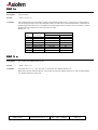
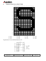
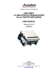
8.
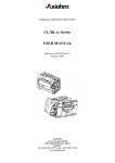
CHARACTER CELL STRUCTURE
16 15 14 13 12 11 10 9
8
7
6
5
4
3
2
1
1
2
3
4
5
6
7
8
9
10
11
12
13
14
15
16
17
18
19
20
21
22
23
24
P1 = 00H
P2 = 00H
P3 = 00H
P4 = 00H
P5 = 00H
P6 = 00H
P7 = 3FH
P8 = 00H
P9 = C0H
P10 = 7FH
P11 = 80H
P12 = E0H
Organisation of a user-defined character cell
A620 & A621
User Manual page 37 / 37
Ref : FDE - 3104471
Issue : B