1
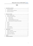
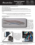
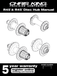
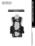
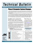
Type Internal upper stack height InSet™ / Tapered / 1.5 External Internal | External ream depth lower stack height Headset Name S.H.I.S Standard InSet1 ZS44/28.6|ZS44/30 InSet2 ZS44/28.6|ZS56/40 InSet4 ZS49/28.6|ZS49/30 InSet3 ZS44/28.6|EC49/40 InSet5 ZS49/28.6|EC49/40 InSet7 ZS44/28.6|EC44/40 InSet8 ZS44/28.6|EC44/33 1-1/8 | 1.5" Tapered EC34/28.6|EC49/40 1.5 | 1-1/8" Devo EC49/28.6|EC49/30 1.5" EC49/38.1|EC49/40 Headtube Opening Upper Lower Upper Lower Upper Lower Upper Lower Upper Lower Upper Lower Upper Lower Upper Lower Upper Lower Upper Lower Headtube I.D. Fork Steerer Tube 44.00 mm (+0.00 -0.05) 1-1/8" 44.00 mm (+0.00 -0.05) 1-1/8" 44.00 mm (+0.00 -0.05) 1-1/8" 55.95 mm (+0.00 -0.05) 1.5" 49.61 mm (+0.00 -0.04) 1-1/8" 49.61 mm (+0.00 -0.04) 1-1/8" 44.00 mm (+0.00 -0.05) 1-1/8" 49.61 mm (+0.00 -0.04) 1.5" 49.61 mm (+0.00 -0.04) 1-1/8" 49.61 mm (+0.00 -0.04) 1.5" 44.00 mm (+0.00 -0.05) 1-1/8" 44.00 mm (+0.00 -0.05) 1.5" 44.00 mm (+0.00 -0.05) 1-1/8" 44.00 mm (+0.00 -0.05) 33.95 mm (+0.00 -0.05) 49.61 mm (+0.00 -0.04) 49.61 mm (+0.00 -0.04) 49.61 mm (+0.00 -0.04) 49.61 mm (+0.00 -0.04) 49.61 mm (+0.00 -0.04) Stem Cap Bolt Torque = 1.7Nm (15 in.lbs) 1 upper stack height = upper cup + bearing cap. lower stack height = lower cup + baseplate 2 convertable to fit a 1-1/8" or 1.5" steerer tube, depending on baseplate and/or bearing cap 3 InSet™ / Tapered / 1.5 Made in the USA All Chris King Precision Components products are manufactured in the USA using industry leading environmental and quality control standards. Printed on 100% post consumer recycled paper fiber. Printed with soy ink. Chris King Precision Components 2801 NW Nela Street, Portland, Oregon 97210 800.523.6008 | www.chrisking.com | [email protected] 1-1/4" 1-1/8" 1.5" 1-1/8" 1-1/8" 1.5" 1.5" Fork Crown Seat O.D. Stack Height 8.2 mm 4.2 mm 30.1 mm 8.2 mm 5.6 mm 39.8 mm 8.0 mm 4.0 mm 30.1 mm 8.2 mm 14.2 mm 39.8 mm 8.0 mm 14.2 mm 39.8 mm 8.2 mm 14.0 mm 39.8 mm 8.2 mm 33.1 mm 39.8 mm 30.1 mm 39.8 mm 14.0 17.7 14.2 18.1 14.2 18.1 14.2 mm mm mm mm mm mm mm 1 Min. Ream Depth Convertability 9.5 mm 9.5 mm 9.5 mm 11.0 mm 16.0 mm 16.0 mm 9.5 mm 20.0 mm 16.0 mm 20.0 mm 9.5 mm 9.5 mm 9.5 mm 9.5 mm 9.5 mm 20.0 mm 20.0 mm 20.0 mm 20.0 mm 20.0 mm 2 3 convertable to fit a 1-1/8" or 1-1/4" tapered steerer tube, depending on baseplate Additional Support Check our web site often for updated technical information produced in an effort to help you, our customers, stay on your bike. Visit: chrisking.com/tech. Additional Questions? Please email us at [email protected] or call the Customer Service Hotline at 800-523-6008. Warranty Chris King Precision Components warrants its bicycle headsets to be free from defects in materials or workmanship for a period of 10 years from the original date of purchase. Any Chris King product that is found by Chris King Precision Components to be defective in materials or workmanship will be repaired or replaced at the sole discretion of Chris King Precision Components providing it is returned to the factory freight prepaid. This warranty does not cover damage or failure resulting from misuse, abuse, alteration, neglect, normal and reasonable wear and tear, crash or impact, failure to perform routine maintenance as instructed, or use other than that for which the product was intended. If a defect is found, our entire liability and your sole remedy shall be, at our option, free repair or replacement of the Chris King product. Chris King Precision Components shall not be held liable for any indirect, special, or consequential damages. The warranty does not cover any Chris King Precision Components product where the serial number has been altered or removed. This written express warranty is in lieu of all other warranties, implied or expressed, and does not cover any representation or warranty made by dealers beyond the provisions of this warranty. This warranty gives you specific legal rights, and you may also have other rights which vary state to state. Rev. 1/13-A Thank you for your purchase! Congratulations! You have just purchased what many people regard as the finest headset in the world. Since 1976 Chris King has been supplying cyclists with the best made, most reliable headsets you can buy. With proper installation and maintenance you can expect to enjoy the many years of the legendary quality and performance built into each and every component we make. Compatibility The InSet and 1.5 are NoThreadSet™ designs. See the InSet / 1.5 Specifications table for required headtube dimensions. Do not attempt to modify a different style headtube to fit this dimension. Contact the bicycle frame manufacturer or an authorized Chris King dealer to verify frame compatibility. Installation We recommend that the headset installation procedure be performed by a professional bicycle mechanic. Reaming and Facing of Headtube Proper preparation of the headtube and fork crown is essential for optimal headset performance. Every headtube must be reamed and faced, even if the frame is new and appears to be prepared at the factory. Headtube bore (inner diameter) and ream depth must measure to the exact specifications indicated in the InSet Specifications table. *For Carbon frames compatibility check with frame manufacturer Chris King frame cutting tools: To ensure optimal press fit, alignment and longevity, the use of high quality reaming and facing tools (such as those manufactured by Chris King) is required. These cutting tools are engineered to machine metal bicycle frames to precise diameters and depths. See the Chris King Reaming and Facing Tool Manual for detailed instructions on reaming and facing procedure. 1. Ream the headtube to ensure that the head tube bore is the proper diameter, depth and roundness. Be sure to use the reamer stop plate in conjunction with the reamer tool to ensure that the headtube is reamed to the proper depth. Reaming the headtube deeper than the frame manufacturer’s specifications may compromise the structural integrity of the headtube. An improperly reamed head ube may cause frame failure, loss of control of the bicycle while riding, serious injury or death. 2. Face the headtube to ensure that the ends are square and parallel to each other, and that all paint and anodization material is removed from the frame-headset interface. 3. Using a deburring tool, small file or sand paper, carefully remove any sharp edges or burrs and slightly round, or chamfer, the inside edges of the headtube at the top and bottom to prevent scraping any metal from the cups during installation. 4. Clean head tube to remove any chips, shavings, and/or cutting oil. Installation of Bearing Cups Chris King headset cup press adapter kit: To ensure proper installation, the use of a Chris King headset cup press adapter kit is necessary. Our press adapters help to correctly align the bearing cups with the headtube and prevent damage to the bearings by directing pressure only and evenly over the bearing cups. The kit includes a baseplate installation adapter that prevents damage to the baseplate by protecting the conical bearing contact surface from the crown race setting tool. Sizes are available to fit all popular headset pressing and setting tools. 1. Proper press fit should not exceed the measurement found in the InSet and 1.5 Specifications table. Do not file or otherwise remove material from the headset cups to make them fit. 2. Be sure that surfaces of headset cup press adaptors are clean and free of burrs to minimize risk of marring headset cup finish during installation. Press in both bearing cups using a headset cup installation press fitted with Chris King headset cup press adapters. Check to ensure the cups are seated flatly against the ends of the head tube. Preparation of Fork and Installation of Baseplate Proper preparation of the fork is essential for best headset performance. 1. See table for crown seat outer diameter (OD) specifications. The proper baseplate press fit should be with no more than 0.1 mm (0.004”) of interference. 2. Clean to remove any chips, shavings, and/or cutting oil from the crown race seat area. 3. Slide the baseplate, conical side up, onto the fork steer tube. With the beveled side of the Chris King baseplate installation adapter against the baseplate, use a crown race setting tool to set the baseplate. InSet A F B G C H I J D E A. stem cap screw B. stem cap C. star nut D. scuff washer E. GripLock assembly F. GripLock cap G. cap O-ring H. split ring I. bearing ring J. bearing ring O-ring K. upper bearing cup L. lower bearing cup M. baseplate K L M Cutting the Steer Tube Use extreme caution when cutting steer tube to avoid injury. 1. Insert fork, with baseplate installed, into frame. 2. Slide GripLock cap assembly, then spacers (if needed), and then the stem over steerer tube. Scribe a line flush with top of stem. 3. Remove items from steerer tube and mark another line 3 mm below the first. Cut on the lower line using a hacksaw and saw guide. 4. Remove all sharp edges from inside and outside of steerer tube. With a file or sandpaper, round outside edge of tube to avoid shearing GripLock cap O-ring upon installation. Installation of Star Nut Note: star nut is not included in 1.5 NoThreadset assembly. We recommend using a retention device such as the Chris King PreLoader when using a straight 1.5 steerer tube. *For forks with Carbon steerers please refer to the Fork Manufacturers instructions regarding pre-load devices 1. Thread star nut onto installation tool. (If installation tool is not available, thread bolt well into star nut and use it to drive the star nut 15 mm below the top of the steer tube.) 2. With a soft hammer or mallet, drive star nut straight into steer tube until tool contacts top of steer tube. Unscrew tool from star nut. GripLock™ Assembly The GripLock is shipped pre-assembled. If it has been disassembled, fit assembly together as shown in diagram. Follow the procedure below. 1. Place thin bearing ring O-ring into outer groove of bearing ring. 2. Place split ring into bearing ring. 3. Snap the bearing ring and split ring into the GripLock cap. 4. Feed cap O-ring into the groove created by the assembled parts. GripLock™ Installation, Final Assembly and Adjustment 1. Remove all sharp edges from inside and outside edges of the cut steerer tube with a file or sand paper to avoid shearing the cap O-ring during installation. 2. Apply thin layer of grease onto cap O-ring. 3. Insert fork into frame. 4. Place assembled GripLock onto steerer tube. In most cases, the assembly will easily slide onto steerer. If cap O-ring hangs up on the top edge of the steerer tube, take care not to shear the O-ring. Gently push the cap O-ring to the side and push the GripLock assembly onto the steerer using steady downward pressure and a slight twisting or rocking motion. 5. Note: If GripLock assembly comes apart during installation, go back to “GripLock Assembly” section and then repeat the installation steps. 6. Slide scuff washer, then any spacers and stem onto steerer tube. Thread stem cap screw through stem cap and into star nut. Tighten to 15 in.lbs. (1.7 Nm) of torque using 5 mm hex wrench. 7. Adjust alignment of stem and then secure stem according to the manufacturer’s specifications. 8. Check headset for proper adjustment. When properly adjusted, the fork will rotate smoothly without play or restriction. Some settling may occur after a few rides; readjust as necessary. New seals will produce some resistance in rotation for the first 50-100 hours of use. Avoid confusing this with rubbing or binding that may result from improper installation, poorly cut spacers, or stems that are not properly faced. We recommend using Chris King Spacers Maintenance Chris King headsets are designed to provide the maximum life of any headset with a minimum of maintenance. Besides an occasional adjustment, the only service necessary is an occasional cleaning and regreasing of the bearings. Riding conditions will dictate how often to service your headset. In wet conditions, service may be necessary as often as every 6 months; in dry conditions, up to every 5 years. GripLock™ Removal 1. Remove stem cap, stem and spacers from steerer tube. Release GripLock “lock” by tapping side of steerer tube with palm of hand or rubber mallet. Do not hit steerer tube from top, as this may damage the headset bearings. Headset parts are available from any authorized Chris King dealer or directly from Chris King Precision Components Headset Removal Do not at any time attempt to remove headset bearings from bearing cups. 1. Remove cups from headtube using a headset cup remover tool. We recommend a Park Tool™ RT-2 on all headsets listed in the specifications table, except for the 1-1/8” | 1.5 tapered headset, which requires the Park Tool™ RT-1. Be sure that tool contacts the inside edges of the cup skirt, not the bearing. 2. To remove baseplate from fork, we recommend using a crown race removal tool to lessen the possibility of warping or deforming the baseplate. If the baseplate is warped, it must be replaced with a new one to ensure proper alignment. If necessary, a 1/4” or 3/8” drift punch can be used for baseplate removal instead. Be sure to alternate strikes on either side of fork crown to lessen the possibility of warping or bending. 3. After removing the baseplate from the fork, check for deformities by placing it on a level surface. If the baseplate does not sit level on the surface and in any way appears to be warped or deformed, it must be replaced for optimal bearing performance. Service of Bearings Do not at any time attempt to remove headset bearings from bearing cups. Chris King sealed bearings have removable snap rings that hold the rubber seals in place. 1. Carefully, using a small screwdriver, pick, or penknife, remove the snap ring by inserting tool into split of snap ring. Gently work one end of the snap ring toward bearing center until it is out of its groove. Follow the ring around with the tool until the snap ring is completely dislodged. 2. Lift and remove exposed rubber seal to access the interior of the bearing. 3. Thoroughly flush the bearing with a light spray lubricant (e.g., WD-40™) and blow dry. 4. Wipe dirt and other contaminants from the seals and snap rings. Used snap rings and seals can be reinstalled unless warped, punctured, or otherwise damaged. If damaged, replacement seals and snap rings are available from any authorized Chris King dealers or directly from Chris King Precision Components. Some solvents, synthetic lubricants, and greases with high-pressure additives may attack and damage seals and other nonmetallic materials. Minimize exposure to these substances and thoroughly dry bearing assembly after cleaning. Do not use citrus based cleaners 5. Lay a bead of waterproof grease around the top of the bearing. Rotate the inner race to work grease throughout the ball area. 6. Reinstall rubber seal between inner and outer bearing race. *Be sure to reinstall seals and snap ring in their orginal orientation. 7. Insert one edge of snap ring into groove of outer bearing race. Press along entire groove until snap ring is fully seated; a small gap should be visible between both ends of the snap ring. 8. Turn inner race of bearing by hand to test for binding. If bearings do not run smooth, repeat steps 1-8. Binding is often a result of improperly seated seals and/or snap rings.