1
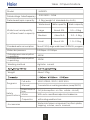
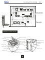
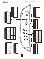
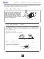
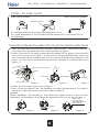
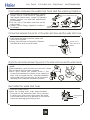
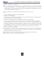
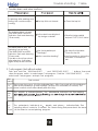
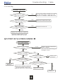
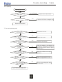
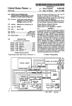
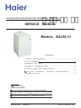
Computerized Automatic Washing Machine
· þÎ ñÊ Ö²
SERVICE MANUAL
Models XQJ60-31
Contents
1.Table of Specifications ...........................................................1
2.Circuit Diagram
3.Names of the Parts................................................................3
4.Usage of Operating Knobs............................................................4
5.Product Briefs and Major Features..................................................5
Key Points in Installa tion,
Adjustment
and Disassembly .. .........7
7.Trouble sh ooting .........................................................................13
8.Exploded view of the components ...................................19
9. Components List
Features:
T op-head model,nice and elegant
Soak wash the wash result is more better
Eccentric plusator better effect
Special No.: HWM5TL
Edition: 2006.07.08
Table Of Specifications
Model
HWM5TL
Rated voltage *rated frequency
230-240V~ 50Hz
Rated wash/spin capacity
5.0kg (weight of standard dry cloth)
Water level
Water level and quantity
Water quantity
Wash capacity
Large
About 50L
3.5~4.5kg
Medium
About 44L
2.0~3.5kg
Small
About 35L
1.0~2.0kg
of different wash capacity
Standard water consumption
About 150L (Large wate r level, NORMAL program)
Water inlet pre ssure
0.03Mpa~0.78M pa
Ratedpowerconsumption
in washing
Ratedpowerconsumption
in spinning
450W
300W
Washing method
Agitater current
Weight
About 37kg
Programs
Safety
specifications
Accessories
Full auto
HE AVY, NOR MAL , GE NT L E , QU ICK WAS H
Manual
F ree selection on washing procedures (except QU ICK )
Power source
fuse
5A (interception on the whole circuit)
Motor
With auto-resett hermalp rotectiondevice
Capacitor
with safeguardfunction
Water inlet pipe component, bottom plate,
tapping screws, user's manual,
1
Overall Dimension Sketch
540
56
0
940
Unit:mm
Circuit Diagr am
The capacitor coil L is used to protect the circuit,please do not dismantle it
Disturbance
Controller
Retractor
R/W
Drain Pump
5A
White
C
L
B rown
B rown
Fuse
B rown/W hite
B lue/W hite
B lue
Blue
Blue
Black
Red
Blue Coldwater Gray
inlet valve
Blue
Hot water
Blue inlet va lve
Red/Blue
Motor
2
Orange
Computer P rogram Controller
Orange
Power switch
Macro-active switch
Purple
R/W
Stop switch
R/W
Pink
Water level sensor
Pink
Gray
Gray
T emperature sensor
The Actual Circuit Diag
Red/Blue
Gray
Orange
ColdWater
inletvalve
Orange
Pink
Purple
Pink
Orange
Black
R/W
Blue
White
Red
C L
Gray
Blue
B rown
B rown/W hite
Gray
B lue/W hite
Stop switch
Control panel seat
Orange
R ed/white
B rown
Macro-active
switch
R/W
Gray
Fuse
B lue
Water level
Sensor
Hot Water
inletvalve
Powerswitch
Temperature sensor
Motor
Disturbance
Controller
ram
Drain pump
Outer switch
Retractor
Blue
Names of the par ts
T op lid
Detergent box
Inner tub
Back faceplate
Control panel film
Water absorption gasket
Power switch
Hot Water inlet
valve
Control panel seat
Power cord
Cold Water inlet
valve
Handle
Hook
Hight Pulsator
Back cover
Cabinet
Drain hose bushing
Adjustable foot
Fixed foot
adjustable foot seam
WASH CYCLE
QUICK WASH
GENT LE
NORMAL
W as hing the bigger, thick er or
heavier dir ty laundr ies
Common was hing
W as hing the wool en tex tiles or under wear
Quick was hing of the light dir ty laundr ies
H eavy
N or mal
Gentle
Qui ck
P r ogr am A ppl i cabl e ci r cu m s t an ces
S elect following four automatic pr ogr ams with the button
PROCESS
SPIN
RINSE
WASH
P us h the button to s elect one or mor e pr ogr ams
fr om s oak , was h r ins e and s pin.
WAT ER
LEVEL
LITT LE
MEDIUM
LARGE
HEAVY
SELECT
P us h the button to s el ect the r es er ve
was hing time among 4 hour
8 hour
12 hour
24 hour
D e l ay s t a r t b u t t o n
DELAY START
T IMER ON
T IME REMAINING
START
PAUSE
P us h
or
to s el ect
was h cycl e pr oces s
water
level temp s elect four
function.
F ac t i o n s e l e c t b u t t o n
OFF
ON
POWER SWIT CH
T emper atur e of war m water is s uitable
or higher water temper atur e in the
dr um is ex pected.
SOAK
P us h the button once to s witch on the power.
W hen the power is on, pus h the button once
to cut off the power.
T emper atur e of war m water is high
and need to mix with s ome cool water
W ar m/W ar m
H ot/cold
P ow er s w i t ch bu t t on
N o r equir ement on water temper atur e
P r o g r am bu t t o n
T EMP
SELECT
COLD/COLD
WARM/COLD
HOT/COLD
I n pus hing, pus h the button to r es ume oper ating.
I n oper ating, pus h the button to paus e the oper ating.
A fter s wi tch on the power, pus h i t once to s tar t the
was hing machine
" S t a r t /P a u s e " bu t t o n
Cold/Col d
Cool water valve is s et automatically when
was her is s tar ted.
P us h down the button, thr ee types of water inlet
can be s elected col d/cold, war m/war m, hot/cold.
P ay attention to the water in dr um not being
over 50 .
" T emp s el ect " bu t t on
P r o c e du r e s e l e c t i o n b u t t o n
P us h the button to s el ect or adjus t
differ ent water level.
W at e r l e v e l s e l e c t i o n b u t t o n
T he indicator is on, indicating the pr ogr am or
mode s elected and about to r un
T he indicator is off, i ndicating that the pr ogr am
or mode is not s elected
T he indicator is fl as hing, indicati ng the r unning
pr ogr am
I n di c at o r m ad e a n d m e a n i n g
Usage of the
Operation
Knobs
Product Briefs
and Major Features
<1>Product Briefs
(1) Computersequencer
It adopts pouring seal with polyurethane on the surface.The light-emitting diode is sealed with
insulation bushing to avoid humidity.T o avoid splashing,the bottom of the control panel seat
wherethe computer plate is installed adopts enclosed structure,and the surface of the operation
components of the front control board is coated with control panel film.
(2) Structure of the top lid
intergrated top lid structure.
(3) Power transmission system
During washing, the rotation of Motor 1 is transferred to Follower 5 from Drive Wheel 2 through
Belt 3. Meanwhile, Ratchet 7 will be braked by Pawl 8 through the actionforce of the spring, and
the movement will be transferred to Center Gear 9, and then be retarded and transferred to
Tie-rod 10 through a planetary gear mechanismconsisting of Center Gear 9, Planet Gear 10 and
Spin Shaft 4 (inner gear), then Tie-rod 10 is connectedto Pulsator 12 via a spline shaft.Therefore,
Pulsator 12 will movealong with the clockwise and counterclockwise rotation of the Motor 1.
During spinning, the rotation of Motor 1 is transferred to Follower 5 from Drive Wheel 2 through
Belt 3. Meanwhile, Pawl 8 will leave Ratchet 7 by the actionof the puller. Clutch Reed 6is twisted
tightly on the down part of Spin Shaft 4. The Spin tub 13 is connectedto Spin shaft 4 with flange.
The movement of Motor 1 will be retarded by V-belt, and then transferred to Spin shaft 4 and
make the Spin tub 13 to spin.
(4) Damping system
In installing the damping component, please note that the hangers at the motor side are
different from those of the other side. The motor side shall use the yellow spring. The other shall
use white spring.
Product Briefs
(2) Major features
B rand new appearance,top head modle:
1+1 control,simple operation
Automatic power-off function:
Low vibration and low noise:
Alarm against breakdown:
Imbalance-revising function:
:
And Major Features
Key Points in Installa tion, Adjustment and Disassembly
Please install and adjust the washing machineaccordingto the requirement of this manual.
It is important for user's safe and proper using the machine.
Install
the bottom plate
After you open the package,please lean
the washing machinegently down on soft
items ( like the towel cloth, blanket, etc. ).
Install the bottomplate to the bottomof
the machine with the eight screws by
a cross screwdriver, then lift the machine
up gently. See to the figure:
Back
Front
Bottom plate
Screw
Adjust
the installation
Soft items
position
The largest allowed slope of the base of the machineis 2 . The slanting or rough
ground will result in unstable running or stoppage of the machine.Please adjust it
with following methods:
Confirm it's horizontal:
Hang the lead lin e to confirm if it is horizon tal.
Adjust the adjustable foot:
1.T o twist the adjustable foot, please first lift up the side of the foot slightly, loosen
the adjustable nut, and twist the foot.
2.Fasten the nut after adjustment.
Loosen
High
Adjustable nut
Fasten
Adjustable foot
Low
Key Points in Installa tion, Adjustment
and Disassembly
How to changethe direction of the drain hose
Cover outer drain hose to drain outlet of washing machineand fasten with drain hose clamp.
Usage of the drain hose
0.8m<H<1.2m
The drain hose must be hang up when using the washing machine.The high of the
drain hose less than 1.2m.
Key Points in Installa tion, Adjustment and Disassembly
Confirm the water faucet
Water faucet, not suitable
Water faucet, suitable
Outlet end surface
It is required that the front end shall be longer than 10cm.
The outlet end surface of the faucet shall be flat and smooth. If not please file it to
avoid leakage.
Conn ectio n betw een th e water in let hos e jo in ter and th e water faucet
1.Press the lower end of the lock lever and push down the slider. Take off the water inlet
hose jointer from the water inlet hose component.See to Figure 1.
2.Loosen the screw till the water faucet can be accessed. Put the jointer of the water inlet
hose on the faucet. See to Figure 2. (If the faucet is too large and the jointer can not be
set on the water faucet, please loosen the four screws and take out the bushing in the
jointer. The front end of the faucet must be smooth, otherwise it may leak water. See to
Figure 3.)
Water inlet hose jointer
Screw
Slider
Nameplate
Screwdriver
Lock lever
Water inlet hose
Figure 1
Figure 2
Bushing
Figure 3
3.Fasten the four screws evenly. See to Figure 4.
4.T ake off the nameplate. T wist the fastening nut as per the indication of the figure to
seal up the outlet end surface of the faucet. See to Figure 5.
Remarks:
Before installation, the threading is 4mmabove the upper surface of the nut. After
installation, the threading is 2mm above the upper surface of the nut. See to Figure 6.
About 4mm
before twisting;
about below 2mm
after twisting
Nut
Figure 4
Figure 5)
Figure 6
Key Points in Installa tion, Adjustment and Disassembly
Conn ectio n betw een the water in let hose and the was hin g machin e
1.Do not take off the water absorption cushion.
Please check if the cushion is dropped or
damaged before each usage. If it happens
please contact our after-sale department
immediately.
2.Put the nut of the water inlet hose on the
valve jointer.
3.Fasten the nut. Swing it gently to confirm if Jointer of the
it's suitable.
water inlet valve
Nut of the water inlet hose
Water absorption cushion
Connection between the join ter of the water inlet hos e and the water inlet hos e
1.Push down the slider. Insert the water inlet
hose into the jointer.
2.Hang the lock lever to the jointer. Release
the slider till a click sound is heard.
Locking lever
Jointer of the
water inlet hose
Slider
Check the connection between the jointer of the water inlet hos e and the water faucet
1.Swing the hose gently to confirm if it is fastened
stable.
2.After installation, open the faucet to check if it leaks.
3.Do not bend the hose with overstrain.
4.Each time before use please check if the
connection between the jointer of the water inlet
hose and the water faucet, and the installation
of the water inlet hose are firm, so as to prevent
dropping from improper installation position.
Dismantle the water inlet hose
1.Close the water faucet.
2.Press the locking lever. Push down the slider .
Then pull off the water inlet hose. If the machine
is used more than once ever y week, the jointer
of the water inlet hose can be kept on the faucet
to prevent damaging the fixing screw.
Locking lever
Slider
Key Points in Installa tion, Adjustment and Disassembly
2. Key points
in Disassembly
Points of attention in maintenance
(1) General attention
Be sure to pull off the power plug in disassembly or maintenance.
The wiring between the conductionwires mostly adopts AMP terminal. Keep the terminal in
good condition during dismantling or maintenance.
In inserting the conducting wires, be sure to plug the pins to the root and make it hard to be
pulled out.
If welding is needed,be careful not to touch the plastic or other insulation parts with the iron.
When connectingthe wires, be sure to keep the wire away from the mobile parts like the belt,
radiating pulley and jib etc., and the sharp protruding parts and the parts with high temperature
(motor). Connect and fix the wires as per their original mode.
If there's metal object at the wire fixing point, be sure to insulate with insulation materials.
Retain the dismantled screws for future usage in installation.
(2) Points of attention in usage of electric components
In case that the power is on, the earthing circuit of the computersequencer can have 220V
voltage to earth. T ake care not to get electric shock.
Store the computersequencer and driver under 4 -30
. Avoid direct sunlight.
In trouble-shooting, it may require hot-line work. Please be extremely careful to avoid electric
shock.
<1>Thepart of control panel seat
(1) Method of opening the control panel
a. Open the back cover. Loosen the two locking belt fixed on the cabinet (used in inner wiring),
to loosen the inner wiring.
b. Loosen the four screws used to install the control panel seat , lift the control panel from
rear to up forwards to dismantle it from the cabinet. Then move it forwards several times to
pull the control panel seat to the rear side.
Attention:
Do not lift the control panel seat by force, otherwise the control rod may get transformed,
and the jointer part of the connecting pipe of the water level switch may be loosened,
or the connectingpipe may be broken and leak gas.
After opening the control panel seat, hold it with one hand or lean it on supporter like the wall.
Do not put it down. Otherwise it may pull the wire unit and connectingpipe.
Key Points in Installa tion, Adjustment and Disassembly
(2) Points of attention in assembly:
Fix the wiring in the control panel seat to its original position. Do not make it touch sharp
corner and mobile position. The space surrounding the computersequencer is rather narrow.
Please dispose it carefully and do not make the wire squeezed into the gapbetween the front
control board and the control panel seat.
When installing control panel seat to cabinet, please check if it is correct .
<2>The cabinet and outer tub component
(1) Method of disassembling
a. Loosen the two motor bolt unit to dismantle the motor. To adjust the tension of the belt, loosen
the bolts and move the motor left and right.
b. Loosen the four fastening screws to dismantle the Transisting guard shield.
c. Loosen the two fastening bolts and dismantle the axis to dismantle the Electro-magnet iron.
d. In dismantling the drain valve, first loosen the screws, then rotate combinationpart with the
drain hose, overflow hose and outer tub slowly to make it loose. Then dismantle the drain valve.
e. In dismantling the inner tub, first take off the outer tub cover, then dismantle the pulsator, finally
dismantle the inner tub. Handle with care when taking the inner tub off from the outer tub.
(2) Points of attention in assembly
In installation of the drain valve, please smear a pieceof 801 glue at the connectionpart
between the drain valve and outer tub and between the overflow hose and drain hose to
guarantee that the drain valve will not leak.
T ake care not to scratch the cabinetand influence the appearanceof the machine.
In fastening the screws, make it tight without sliding.
Trouble-shooting
T able
1. Trouble alarm and solve method
In spinning after washing and
rinsing, the machine stops
running.
The top lid is not closed.
The draining does not work,
(The WASH,RINSE and SPIN
indicator flash and alarming
10 seconds)
Is the drain hose blocked
by foreign material?
Clean the foreign materi al
and push S T AR T /PAU S E button
Are the laundries put
slantingly?
Re-order the laundries.
Close the top lid.
L evel the machine in right position.
After about 10 seconds,it will
start .
The safety switch acts. The
spinning can not work
(The WASH,RINSE and SPIN
indicator flash and alarming
10 seconds)
If trouble can not be solved
after alarming, it will alarm
again every a few minutes.
Is the machine slanting?
Close the top lid.
2. T est program (test without water)
Push and hold the " PROGRAM SELECT
" and "PROCEDURE SELECT
" buttons, then push
to
down the power switch to enter buzzer T est program. Push the " PROCEDURE SELECT
select wash T est program and spin T est programs.
Test
name
Test content
B uzzer The buz zer ring s once. All of the indicators flash . After 3 se conds, all of the indicators
flash and the buzzer rin gs inter mittebtly 3 times(0.3s c onnected,0.3s s hutoff). The
T est
program power is switch ed off automatically after finis hing.
The
Wash
T est
the
program
WASH
indicator flashes
program select
the
standard
indicator is on. Run washing
button
The
standard indicator is on
wash and rinse
indicators flash. Run
S pin
spinning without water for 5 minutes. The alarm during that procedure is the same
T est
program as the alarm in normal spinning program.
Trouble-shooting
T able
3. Trouble-shooting charts
1. No action(The indicator is off)
Confirm that there's n o power failur e,
and the power plug is ins erted reliably.
Th e power sw itch is at "On" mode.
Measure the voltage
of the two ends of the power in put
of the sequencer.
Exist
Replace the sequencer.
Pull off
the power Not exist
plug
Measu re the resis tance
between the inner terminal in the
yellow palst ic part of the wire unit and
the terminal of the power
receptacle.
The resistance
is 0.
Infinite
Measu re the resis tance
between the inner terminal in the
yellow palst ic part of the wire unit and
the black wire of wire unit
Measu re the resis tance
between the inner terminal in the
blue palstic part of the wire unit and
the orange wire of wire unit
The resistance
is 0.
Infinite
Replace the wire unit.
The resistance
is 0.
Replace the
power cord.
Infinite
Check if the fuse is burnt?
No
Measu re the resis tance
of the two terminal of power
sw itch connected with orange wire.
Infinite
Replace power switch.
Yes
Replace the fuse.
At this time please check if the other
electric components work normally.
The resistance
is 0.
Replace the wire unit.
Trouble-shooting
T able
2. No water filling
Switch on the power. Push
the START/P AUSE button.
Confirm the action sound
of the water inlet valve?
Remove the foreign materials of the water
inlet valve filter screen or raise the water
pressure to 0.03Mpa-0.78MPa before use.
Exist
Not exist
Measure the voltage
of the two ends of the
water inlet valve?
Exist
Replace the water inlet valve.
Not exist
Measure the voltage
of the two ends of the
computer seq uencer?
Exist
Replace the wire unit.
Not exist
Replace the computer sequencer.
At this time please check if the
water inlet valve works normally.
Start the test without water.
Enter no-water washing.
Check the action of the
motor.
It acts.
Not exist
Measure the voltage of the
two ends of the motor.
Not exist
Exist
Replace the
wire unit.
Measure the voltage
of the two ends of the output of
the computer se quencer.
Not exist
Replace the computer se quencer.
At this time please check if the
capacitor and motor works normally.
Please check the transmission
system carefully.
If it is normal of the bearing part
locking the clutch.
Exist
If th e motor overheat
protector acts?
Yes
Please check
the reason.
No
If the capacitor has broken
circuit or s hort circuit?
No
Yes
Replace the motor.
Replace the
capacitor.
Trouble-shooting
4. No draining
T able
Set rinse or spin.
Start the machine.
Check if the E lectro-magnet iron acts?
Roll up normally Check the drain system like
the drain valve etc.
No
Measu re the
voltage of the two ends of
the E lectro-magnet ir on
Exist
Re place the Electro-magnet ir on
No Exist
Measure the voltage
of the two ends of the output
of the computer sequencer.
Exist
Replace the wire unit.
No Exist
Replace the computer
sequencer.
At this time check if the Electro-magnet iron
works normally.
5. Keep filling water
Open the water faucet with out
swit ching on the power.
If the water can fill into
the water inlet valve
Yes
Replace the water inlet valve.
No
Switch on the power. Do not
push the "Start/Pause" button.
If the water can fill into
the water inlet valve
Yes
At this time please check if the
water inlet valve is well.
No
Check if the wire connecting
the computer board to the
water level s witch is bad?
Replace the computersequencer.
Yes
Replace the wire unit.
No
Selec t "low " water leve l
and start the machine to
check if the gas cell
has water?
Yes
It leaks gas. Please check and
repair the gas guide system.
Please smear 801 glue in installation
of the connectingpipe.
Please smear 801 glue in installation
of the gas cell cover.
Yes
Clear various factors like
the foreign Materials.
Blow from the connecting pipe to the
water level sensor and gas cell to see
if there's blocking.
No
Check if the gas guide sys tem
is blocked?
No
Replace the water level switch.
Trouble-shooting
T able
6. No spinning
The washing and
draining are normal.
Check the On/Off point of the
safety switch.
No On/Off point
Replace the safety switch.
Normally
Check if the clutch pawl
is pulled enough.
No
Replace the Electro-magnet iron
Yes
Replace the retarder .
7. T oo much spinning noise
If t he noise of the motor
is too much?
Yes
Replace the motor.
No
If the motor is fastened
tightly?
Yes
If the bearing of the retarder
is wel l?
No
No
Fasten the motor.
Replace the bearing.
Yes
If the departing of
the ratchet and pawl
is w ell?
Yes
Adjust the angle or the distance of
the ratchet and pawl. The distance
between the ratchet and the pawl is
above 2mm.
Yes
Adjust the cabinet to acquire
balance.
Yes
Adjust the gap between the
balance ring and the outer tub.
No
If the machine body
vibrate resonantly with the
cabinet?
No
If the balance ring is ru bbing
the outer tub cover?
No
If the connecting pipe
or the wire unit bumps
the outer tub?
No
The hanger seat is lack of oil.
Inject oil at the hanger seat.
Yes
Fix the connecting pipe and
the wire unit.
Trouble-shooting T
8. T oo much noise in washing
If the noise of the motor
is too much?
No
If the motor fast ened tightly?
Yes
No
Replace the motor.
Fasten the motor.
Yes
If t he inner gear of the retarder
is engaged well?
No
Replace the retarder.
Yes
If the belt is too tight
or loose?
Yes
Adjust the belt.
No
If the radiating pulley is
loose?
Yes
Fasten the radiating pulley.
No
The pulsator is rubbing the
bottom of the inner tub.
Yes
Add pulsator gasket.
able
Sincere Forever
Haier Group
Haier Industrial Park, No. 1, Haier Road
266101,Qingdao,China
http://www.haier.com