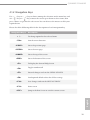
1
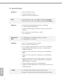
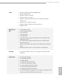
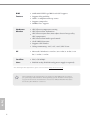
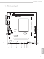
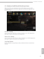
User Manual
Version 1.1
Published April 2014
Copyright©2014 ASRock INC. All rights reserved.
Copyright Notice:
No part of this documentation may be reproduced, transcribed, transmitted, or
translated in any language, in any form or by any means, except duplication of
documentation by the purchaser for backup purpose, without written consent of
ASRock Inc.
Products and corporate names appearing in this documentation may or may not
be registered trademarks or copyrights of their respective companies, and are used
only for identification or explanation and to the owners’ benefit, without intent to
infringe.
Disclaimer:
Specifications and information contained in this documentation are furnished for
informational use only and subject to change without notice, and should not be
constructed as a commitment by ASRock. ASRock assumes no responsibility for
any errors or omissions that may appear in this documentation.
With respect to the contents of this documentation, ASRock does not provide
warranty of any kind, either expressed or implied, including but not limited to
the implied warranties or conditions of merchantability or fitness for a particular
purpose.
In no event shall ASRock, its directors, officers, employees, or agents be liable for
any indirect, special, incidental, or consequential damages (including damages for
loss of profits, loss of business, loss of data, interruption of business and the like),
even if ASRock has been advised of the possibility of such damages arising from any
defect or error in the documentation or product.
The terms HDMI™ and HDMI High-Definition Multimedia Interface, and the HDMI
logo are trademarks or registered trademarks of HDMI Licensing LLC in the United
States and other countries.
This device complies with Part 15 of the FCC Rules. Operation is subject to the following
two conditions:
(1) this device may not cause harmful interference, and
(2) this device must accept any interference received, including interference that may cause undesired operation.
CALIFORNIA, USA ONLY
The Lithium battery adopted on this motherboard contains Perchlorate, a toxic substance
controlled in Perchlorate Best Management Practices (BMP) regulations passed by the
California Legislature. When you discard the Lithium battery in California, USA, please
follow the related regulations in advance.
“Perchlorate Material-special handling may apply, see www.dtsc.ca.gov/hazardouswaste/
perchlorate”
ASRock Website: http://www.asrock.com
Contents
Chapter 1 Introduction
1
1.1 1
Package Contents
1.2 Specifications
2
1.3 Motherboard Layout
5
1.4 7
I/O Panel
Chapter 2 Installation
8
2.1 9
Installing Memory Modules (DIMM) 2.2 Expansion Slots (PCI Express Slots)
11
2.3 Jumpers Setup
12
2.4 Onboard Headers and Connectors
13
Chapter 3 Software and Utilities Operation 17
3.1 17
Installing Drivers
3.2 A-Tuning
18
3.3 Intel® Smart Connect Technology
20
3.4 ASRock Cloud 25
3.5 Start8
35
Chapter 4 UEFI SETUP UTILITY
38
4.1 38
Introduction
4.1.1 UEFI Menu Bar
38
4.1.2 Navigation Keys
39
4.2 Main Screen
40
4.3 Advanced Screen
41
4.3.1 CPU Configuration
42
4.3.2 Chipset Configuration
44
4.3.3 Storage Configuration
46
4.3.4 Intel® Smart Connect Technology
47
4.3.5 Super IO Configuration
48
4.3.6 ACPI Configuration
49
4.3.7 USB Configuration
51
4.3.8 Trusted Computing
52
4.4 Tools
53
4.5 Hardware Health Event Monitoring Screen
55
4.6 Security Screen
56
4.7 Boot Screen
57
4.8 Exit Screen
59
Q1900M / D1800M
Chapter 1 Introduction
Thank you for purchasing ASRock Q1900M / D1800M motherboard, a reliable
motherboard produced under ASRock’s consistently stringent quality control.
It delivers excellent performance with robust design conforming to ASRock’s
commitment to quality and endurance.
In this manual, Chapter 1 and 2 contains the introduction of the motherboard
and step-by-step installation guides. Chapter 3 contains the operation guide of the
software and utilities. Chapter 4 contains the configuration guide of the BIOS setup.
Because the motherboard specifications and the BIOS software might be updated, the
content of this documentation will be subject to change without notice. In case any
modifications of this documentation occur, the updated version will be available on
ASRock’s website without further notice. If you require technical support related to
this motherboard, please visit our website for specific information about the model
you are using. You may find the latest VGA cards and CPU support list on ASRock’s
website as well. ASRock website http://www.asrock.com.
1.1 Package Contents
ASRock Q1900M / D1800M Motherboard (Micro ATX Form Factor)
ASRock Q1900M / D1800M Quick Installation Guide
ASRock Q1900M / D1800M Support CD
2 x Serial ATA (SATA) Data Cables (Optional)
1 x I/O Panel Shield
English
•
•
•
•
•
1
1.2 Specifications
Platform
• Micro ATX Form Factor
• All Solid Capacitor design
• High Density Glass Fabric PCB
CPU
• Intel® Quad-Core Processor J1900 (2 GHz) (for Q1900M)
• Intel® Dual-Core Processor J1800 (2.41 GHz) (for D1800M)
Memory
• Dual Channel DDR3/DDR3L Memory Technology
• 2 x DDR3/DDR3L DIMM Slots
• Supports DDR3/DDR3L 1333/1066 non-ECC, un-buffered
memory
• Max. capacity of system memory: 16GB
(see CAUTION)
Expansion
Slot
• 1 x PCI Express 2.0 x16 Slot (PCIE2 @ x1 mode)
• 2 x PCI Express 2.0 x1 Slots
Graphics
•
•
•
•
•
•
•
•
•
English
Audio
2
Intel® 7th generation (Gen 7) graphics
DirectX 11.0, Pixel Shader 5.0
Three graphics output options: D-Sub, DVI-D and HDMI
Supports HDMI Technology with max. resolution up to
1920x1200 @ 60Hz
Supports DVI-D with max. resolution up to 1920x1200 @
60Hz
Supports D-Sub with max. resolution up to 1920x1200 @
60Hz
Supports Auto Lip Sync, Deep Color (12bpc), xvYCC and
HBR (High Bit Rate Audio) with HDMI Port (Compliant
HDMI monitor is required)
Supports HDCP with DVI-D and HDMI Ports
Supports Full HD 1080p Blu-ray (BD) playback with DVI-D
and HDMI Ports
• 5.1 CH HD Audio (Realtek ALC662 Audio Codec)
• Supports Surge Protection (ASRock Full Spike Protection)
Q1900M / D1800M
PCIE x1 Gigabit LAN 10/100/1000 Mb/s
Realtek RTL8111GR
Supports Wake-On-WAN
Supports Wake-On-LAN
Supports Lightning/ESD Protection (ASRock Full Spike
Protection)
• Supports LAN Cable Detection
• Supports Energy Efficient Ethernet 802.3az
• Supports PXE
LAN
•
•
•
•
•
Rear Panel
I/O
•
•
•
•
•
•
1 x PS/2 Mouse Port
1 x PS/2 Keyboard Port
1 x D-Sub Port
1 x DVI-D Port
1 x HDMI Port
3 x USB 2.0 Ports (Supports ESD Protection (ASRock Full
Spike Protection))
• 1 x USB 3.0 Port (Supports ESD Protection (ASRock Full
Spike Protection))
• 1 x RJ-45 LAN Port with LED (ACT/LINK LED and SPEED
LED)
• HD Audio Jacks: Line in / Front Speaker / Microphone
Storage
• 2 x SATA2 3.0 Gb/s Connectors, support NCQ, AHCI and
Hot Plug
Connector
•
•
•
•
•
•
•
•
•
English
1 x Print Port Header
1 x COM Port Header
1 x TPM Header
1 x Chassis Intrusion Header
1 x CPU Fan Connector (3-pin)
1 x Chassis Fan Connector (3-pin)
1 x 24 pin ATX Power Connector
1 x Front Panel Audio Connector
2 x USB 2.0 Headers (Support 3 USB 2.0 ports) (Supports ESD
Protection (ASRock Full Spike Protection))
3
64Mb AMI UEFI Legal BIOS with GUI support
BIOS
Feature
•
•
•
•
•
Hardware Monitor
• CPU/Chassis temperature sensing
• CPU/Chassis Fan Tachometer
• CPU/Chassis Quiet Fan (Auto adjust chassis fan speed by
CPU temperature)
• CPU/Chassis Fan multi-speed control
• CASE OPEN detection
• Supports CPU Fanless
• Voltage monitoring: +12V, +5V, +3.3V, CPU Vcore
OS
• Microsoft® Windows® 8.1 32-bit / 8.1 64-bit / 8 32-bit / 8 64bit / 7 32-bit / 7 64-bit
Certifications
• FCC, CE, WHQL
• ErP/EuP ready (ErP/EuP ready power supply is required)
Supports Plug and Play
ACPI 1.1 compliant wake up events
Supports jumperfree
SMBIOS 2.3.1 support
* For detailed product information, please visit our website: http://www.asrock.com
Due to limitation, the actual memory size may be less than 4GB for the reservation
for system usage under Windows® 32-bit operating systems. Windows® 64-bit operating systems do not have such limitations. You can use ASRock XFast RAM to utilize
the memory that Windows® cannot use.
English
4
Q1900M / D1800M
1.3 Motherboard Layout
PS2
Mouse
PS2
Keyboard
CPU_FAN1
DDR3_A1 (64 bit, 240-pin module)
64Mb
BIOS
VGA1
HDMI1
ATXPWR1
DDR3_B1 (64 bit, 240-pin module)
DVI1
USB 2.0
T: USB2
B: USB3
USB 3.0
USB 2.0:
USB0
USB 3.0:
USB1
Top:
RJ-45
RoHS
LAN
Center:
FRONT
Top:
LINE IN
Bottom:
MIC IN
CMOS
Battery
PCIE1
AUDIO
CODEC
PCIE2
SPEAKER1
Super
I/O
1
PCIE3
CLRCMOS1
1
CI1
LPT1
1
1
COM1
PANEL1
USB4_5
1
PLED PWRBTN
SATA2_2
TPMS1
USB6
1
1
1
1
1
HDLED RESET
English
HD_AUDIO1
SATA2_1
5
No. Description
English
6
1
CPU Fan Connector (CPU_FAN1)
2
2 x 240-pin DDR3 DIMM Slots (DDR3_A1, DDR3_B1)
3
ATX Power Connector (ATXPWR1)
4
Chassis Fan Connector (CHA_FAN1)
5
Chassis Speaker Header (SPEAKER1)
6
SATA2 Connector (SATA2_1)
7
System Panel Header (PANEL1)
8
SATA2 Connector (SATA2_2)
9
Clear CMOS Jumper (CLRCMOS1)
10
USB 2.0 Header (USB6)
11
USB 2.0 Header (USB4_5)
12
COM Port Header (COM1)
13
Print Port Header (LPT1)
14
TPM Header (TPMS1)
15
Front Panel Audio Header (HD_AUDIO1)
16
Chassis Intrusion Header (CI1)
Q1900M / D1800M
1.4 I/O Panel
1
3
2
12
11
10
No. Description
No. Description
1
PS/2 Mouse Port
7
Front Speaker (Lime)
2
USB 2.0 Ports (USB_23)
8
Microphone (Pink)
3
HDMI Port
9
USB 3.0 Port (USB1)
4
LAN RJ-45 Port*
10
DVI-D Port
5
USB 2.0 Port (USB0)
11
D-Sub Port
6
Line In (Light Blue)
12
PS/2 Keyboard Port
4
5
6
7
9
8
* There are two LEDs on each LAN port. Please refer to the table below for the LAN port LED indications.
ACT/LINK LED
SPEED LED
Activity / Link LED
Speed LED
Status
Description
Status
Description
Off
Blinking
On
No Link
Data Activity
Link
Off
Orange
Green
10Mbps connection
100Mbps connection
1Gbps connection
English
LAN Port
7
Chapter 2 Installation
This is a Micro ATX form factor motherboard. Before you install the motherboard,
study the configuration of your chassis to ensure that the motherboard fits into it.
Pre-installation Precautions
Take note of the following precautions before you install motherboard components
or change any motherboard settings.
• Make sure to unplug the power cord before installing or removing the motherboard.
Failure to do so may cause physical injuries to you and damages to motherboard
components.
• In order to avoid damage from static electricity to the motherboard’s components,
NEVER place your motherboard directly on a carpet. Also remember to use a grounded
wrist strap or touch a safety grounded object before you handle the components.
• Hold components by the edges and do not touch the ICs.
• Whenever you uninstall any components, place them on a grounded anti-static pad or
in the bag that comes with the components.
• When placing screws to secure the motherboard to the chassis, please do not overtighten the screws! Doing so may damage the motherboard.
English
8
Q1900M / D1800M
2.1 Installing Memory Modules (DIMM)
This motherboard provides two 240-pin DDR3/DDR3L (Double Data Rate 3)
DIMM slots. If only one DIMM module is installed, please install it into DDR3_A1.
It is not allowed to install a DDR or DDR2 memory module into a DDR3/DDR3L
slot; otherwise, this motherboard and DIMM may be damaged.
English
The DIMM only fits in one correct orientation. It will cause permanent damage to
the motherboard and the DIMM if you force the DIMM into the slot at incorrect
orientation.
9
1
2
3
English
10
Q1900M / D1800M
2.2 Expansion Slots (PCI Express Slots)
There are 3 PCI Express slots on the motherboard.
Before installing an expansion card, please make sure that the power supply is
switched off or the power cord is unplugged. Please read the documentation of the
expansion card and make necessary hardware settings for the card before you start the
installation.
PCIe slots:
English
PCIE1 (PCIe 2.0 x1 slot) is used for PCI Express x1 lane width cards. PCIE2 (PCIe 2.0 x16 slot) is used for PCI Express x1 lane width cards. PCIE3 (PCIe 2.0 x1 slot) is used for PCI Express x1 lane width cards. 11
2.3 Jumpers Setup
The illustration shows how jumpers are setup. When the jumper cap is placed on
the pins, the jumper is “Short”. If no jumper cap is placed on the pins, the jumper
is “Open”. The illustration shows a 3-pin jumper whose pin1 and pin2 are “Short”
when a jumper cap is placed on these 2 pins.
Clear CMOS Jumper
(CLRCMOS1)
(see p.5, No. 9)
Default
Clear CMOS
CLRCMOS1 allows you to clear the data in CMOS. To clear and reset the system
parameters to default setup, please turn off the computer and unplug the power
cord from the power supply. After waiting for 15 seconds, use a jumper cap to
short pin2 and pin3 on CLRCMOS1 for 5 seconds. However, please do not clear
the CMOS right after you update the BIOS. If you need to clear the CMOS when
you just finish updating the BIOS, you must boot up the system first, and then shut
it down before you do the clear-CMOS action. Please be noted that the password,
date, time, and user default profile will be cleared only if the CMOS battery is
removed.
If you clear the CMOS, the case open may be detected. Please adjust the BIOS option
“Clear Status” to clear the record of previous chassis intrusion status.
English
12
Q1900M / D1800M
2.4 Onboard Headers and Connectors
Onboard headers and connectors are NOT jumpers. Do NOT place jumper caps over
these headers and connectors. Placing jumper caps over the headers and connectors
will cause permanent damage to the motherboard.
System Panel Header
(9-pin PANEL1)
(see p.5, No. 7)
Connect the power
switch, reset switch and
system status indicator on
the chassis to this header
according to the pin
assignments below. Note
the positive and negative
pins before connecting
the cables.
PWRBTN (Power Switch):
Connect to the power switch on the chassis front panel. You may configure the way to
turn off your system using the power switch.
RESET (Reset Switch):
Connect to the reset switch on the chassis front panel. Press the reset switch to restart
the computer if the computer freezes and fails to perform a normal restart.
PLED (System Power LED):
Connect to the power status indicator on the chassis front panel. The LED is on when
the system is operating. The LED keeps blinking when the system is in S1/S3 sleep state.
The LED is off when the system is in S4 sleep state or powered off (S5).
HDLED (Hard Drive Activity LED):
Connect to the hard drive activity LED on the chassis front panel. The LED is on when
the hard drive is reading or writing data.
English
The front panel design may differ by chassis. A front panel module mainly consists
of power switch, reset switch, power LED, hard drive activity LED, speaker and etc.
When connecting your chassis front panel module to this header, make sure the wire
assignments and the pin assignments are matched correctly.
13
Serial ATA2 Connectors
(SATA2_1:
see p.5, No. 6)
(SATA2_2:
see p.5, No. 8)
These two SATA2
connectors support SATA
data cables for internal
storage devices with up to
3.0 Gb/s data transfer rate.
SATA2_1
SATA2_2
USB 2.0 Headers
(9-pin USB4_5)
(see p.5, No. 11)
(4-pin USB6)
(see p.5, No. 10)
Front Panel Audio Header
(9-pin HD_AUDIO1)
(see p.5, No. 15)
Besides three USB 2.0
ports on the I/O panel,
there are two headers on
this motherboard.
1
P- P+
USB_PWR
GND
This header is for
connecting audio devices
to the front audio panel.
1. High Definition Audio supports Jack Sensing, but the panel wire on the chassis must
support HDA to function correctly. Please follow the instructions in our manual and
chassis manual to install your system.
2. If you use an AC’97 audio panel, please install it to the front panel audio header by
the steps below:
A. Connect Mic_IN (MIC) to MIC2_L.
B. Connect Audio_R (RIN) to OUT2_R and Audio_L (LIN) to OUT2_L.
C. Connect Ground (GND) to Ground (GND).
D. MIC_RET and OUT_RET are for the HD audio panel only. You don’t need to
connect them for the AC’97 audio panel.
E. To activate the front mic, go to the “FrontMic” Tab in the Realtek Control panel
and adjust “Recording Volume”.
English
14
Q1900M / D1800M
Chassis Speaker Header
(4-pin SPEAKER1)
(see p.5, No. 5)
Please connect the chassis
speaker to this header.
Please connect fan cable
to the fan connector and
match the black wire to
the ground pin.
GND
FAN_VOLTAGE
FAN_SPEED
CPU Fan Connectors
(3-pin CPU_FAN1)
(see p.5, No. 1)
Please connect the CPU
fan cable to the connector
and match the black wire
to the ground pin.
GND
FAN_VOLTAGE
FAN_SPEED
ATX Power Connector
(24-pin ATXPWR1)
(see p.5, No. 3)
12
24
1
13
This motherboard provides a 24-pin ATX power
connector. To use a 20-pin
ATX power supply, please
plug it along Pin 1 and Pin
13.
GND
S_PWRDWN#
GND
+3V
SERIRQ#
LAD2
LAD1
LAD3
LAD0
SMB_CLK_MAIN
SMB_DATA_MAIN
PCIRST#
This connector supports Trusted
Platform Module (TPM) system,
which can securely store keys,
digital certificates, passwords,
and data. A TPM system also
helps enhance network security,
protects digital identities, and
ensures platform integrity.
GND
TPM Header
(17-pin TPMS1)
(see p.5, No. 14)
FRAME
This motherboard supports
CASE OPEN detection feature
that detects if the chassis cove
has been removed. This feature
requires a chassis with chassis
intrusion detection design.
PCICLK
Chassis Intrusion Header
(2-pin CI1)
(see p.5, No. 16)
GND
+3VSB
1
English
Chassis Fan Connector
(3-pin CHA_FAN1)
(see p.5, No. 4)
15
Serial Port Header
(9-pin COM1)
(see p.5, No. 12)
Print Port Header
(25-pin LPT1)
(see p.5, No. 13)
This COM1 header
supports a serial port
module.
AFD#
ERROR#
PINIT#
SLIN#
GND
1
SPD7
SPD6 ACK#
SPD5
BUSY
SPD4
PE
SPD3
SLCT
SPD2
SPD1
SPD0
STB#
English
16
This is an interface
for print port cable
that allows convenient
connection of printer
devices.
Q1900M / D1800M
Chapter 3 Software and Utilities Operation
3.1 Installing Drivers
The Support CD that comes with the motherboard contains necessary drivers and
useful utilities that enhance the motherboard’s features.
Running The Support CD
To begin using the support CD, insert the CD into your CD-ROM drive. The CD
automatically displays the Main Menu if “AUTORUN” is enabled in your computer.
If the Main Menu does not appear automatically, locate and double click on the file
“ASRSETUP.EXE” in the Support CD to display the menu.
Drivers Menu
The drivers compatible to your system will be auto-detected and listed on the
support CD driver page. Please click Install All or follow the order from top to
bottom to install those required drivers. Therefore, the drivers you install can work
properly.
Utilities Menu
The Utilities Menu shows the application software that the motherboard supports.
Click on a specific item then follow the installation wizard to install it.
English
To improve Windows 7 compatibility, please download and install the following hot
fix provided by Microsoft.
“KB2720599”: http://support.microsoft.com/kb/2720599/en-us
17
3.2 A-Tuning
A-Tuning is ASRock’s multi purpose software suite with a new interface, more new
features and improved utilities, including XFast RAM and a whole lot more.
3.2.1 Installing A-Tuning
When you install the all-in-one driver to your system from ASRock’s support CD,
A-Tuning will be auto-installed as well. After the installation, you will find the icon
“A-Tuning“ on your desktop. Double-click the “A-Tuning“
icon, A-Tuning
main menu will pop up.
3.2.2 Using A-Tuning
There are five sections in A-Tuning main menu: Operation Mode and Tools.
Operation Mode
Choose an operation mode for your computer.
English
18
Q1900M / D1800M
Tools
Various tools and utilities.
XFast RAM
English
Boost the system’s performance and extend the HDD’s or SDD’s lifespan! Create a
hidden partition, then assign which files should be stored in the RAM drive.
19
3.3 Intel® Smart Connect Technology
Intel® Smart Connect Technology is a feature that periodically wakes your computer
from Windows® sleep state to refresh email or social networking applications. It
saves your waiting time and keeps the content always up-to-date.
3.3.1 System Requirements
•
Confirm whether your motherboard supports this feature.
•
Operating system: Microsoft Windows 8/7 (32- or 64-bit edition)
•
Set the SATA mode to AHCI. If Windows 8/7 is already installed under IDE
mode, directly changing the SATA mode to AHCI may cause Windows 8/7
to crash while booting. If your system is not in AHCI mode, please follow the
instructions below.
There are certain risks. Please backup any important data before operating to avoid
loss.
English
20
1.
Press Win + R simultaneously in Windows 8/7, type "Regedit" into the word
box then click OK.
2.
Enter into HKEY_LOCAL_MACHINE\SYSTEM\CurrentControlSet\services\
msahci in Windows Registry Editor. Double click on the value Start and
change the value from 3 into 0. Click on OK.
Q1900M / D1800M
3.3.2 Setup Guide
Installing ASRock Smart Connect Utility
Step 1
Install ASRock Smart Connect Utility, which is located in the folder at the following
path of the Support CD: \ ASRock Utility > Smart Connect.
Step 2
English
Once installed, run ASRock Smart Connect from your desktop or go to Windows
Start -> All Programs -> ASRock Utility.
21
Step 3
Click the Add button. Take Foxmail as an example, add Foxmail to the Application
list.
Step 4
Select Foxmail from the Application List, then click the arrow pointing right to add
this application to the Smart Connect List.
English
Step 5
Click Apply to enable Smart Connect.
22
Q1900M / D1800M
Step 6
Double-click the Intel® Smart Connect Technology Manager icon
Windows system tray.
in the
Step 7
Drag the slider to configure how often the system will connect to the network to
download updates. Shorter durations will provide more frequent updates, but may
cause more power consumption.
Using Smart Connect
Keep the applications which you wish to connect to the internet and receive
updates while the system is in sleep state running. Foxmail for instance, keep
Foxmail running.
2.
Click on Windows Start -> the arrow next to Shut down, and click on Sleep.
3.
Windows system will enter sleep state.
English
1.
23
English
24
4.
The system will wake up from sleep state periodically, and then start to update
Foxmail. The screen will not display anything so the computer can maintain
minimum power usage. Afterwards, the system will automatically return to
sleep state again.
5.
Upon waking up the system, you will find the new mail that were sent to you
during sleep state are already updated and ready to be read in Foxmail.
Q1900M / D1800M
3.4 ASRock Cloud
ASRock partners with Kloudian to make your mobile devices connect to
your PC seamlessly!
Have you ever been in a situation where you emergently needed certain files in your
computer, however the computer was gazillion miles away out of reach? ASRock Cloud
includes several technologies and software solutions for remotely controlling your
computer, even if the computer is in off mode. For ASRock motherboards with a Realtek®
LAN chip, ASRock Cloud allows users to remotely wake up their computers via the
internet by using a secondary device, such as a smartphone or tablet. Users may use
English
Kloudian® Orbweb.ME Professional to remotely wake up and control their computers, or
they could wake up the computer then use any other preferred remote desktop application.
This motherboard supports Wake-On-WAN with the onboard Realtek® LAN, so you can
connect with your PC from anywhere in the world. You will be able to power your PC on
or turn it off, monitor and take control of it remotely with another smartphone, tablet or
computer.
25
3.4.1 Realtek® Wake-On-WAN
Realtek® Wake-On-WAN allows you to wake up and remote control your home computer
from sleep or shutdown state.
Before configuring this feature, verify the followings on your host computer:
•
Make sure that the "PCIE Devices Power On" is enabled in UEFI SETUP
UTILITY > Advanced > ACPI Configuration.
*The UEFI screen is for reference only. The actual screen may differ by model.
•
English
26
Make sure that the "Shutdown Wake-On-Lan" is enabled in Device Manager >
Network Adapters > Realtek PCIe GBE Family Controller > Advanced.
Q1900M / D1800M
3.4.2 Configuring and Using Orbweb.ME Professional
Kloudian® Orbweb.ME Professional is a remote control software allowing you to easily
access and control the remote host installed with the Orbweb.ME Professional host
software.
Installing Orbweb.ME Professional on the Host Computer
You can find the Orbweb.ME Professional host software in the Support CD or just
download it from http://orbweb.me.
Step 1
Click on the Orbweb.ME Professional installer package file to start installation.
Step 2
Follow the onscreen instructions to complete the installation.
Step 3
When installation completes, reboot the computer.
Signing Up for Host Computer Registration
Step 1
Double-click the Orbweb.ME Professional icon
on your desktop.
Step 2
English
On the Orbweb.ME Portal login page, click Sign Up to create an Orbweb.ME account and
name your host computer.
27
Step 3
You will receive a verification email. Follow the steps in the email to verify your account.
After verifying your account, you can access your PC through web browsers at
http://orbweb.me.
On the Account Verified page, if you click Go to My Computers, you will see the Orbweb.
ME portal page as a client.
Setting Up Shared Folders on Host Computer
Step 1
Double-click the Orbweb.ME Professional icon
on your desktop.
Or, if you just finished signing up for your host computer, you can click Configure this
computer in the screen to begin.
Step 2
Click Folder Settings tab and the default shared folders display.
To add a folder, click
. Select a folder to add it into Orbweb.ME. Then click Save.
English
You can access the documents in these shared folders on the host computer remotely
through Xplorer from your client device.
28
Q1900M / D1800M
REMOTE ACCESS FROM A CLIENT DEVICE
The lastest version of Java is required to be installed to use the Remote Desktop and
Xplorer functions.
Using Remote Wake-Up
Remote Wake-Up allows you to remotely put your host computer to sleep and wake your
host computer up from a client device.
If you use a motherboard with dual LAN ports, please disable one of the LAN ports
to use the Remote Wake-Up function. To do so, go to Control Panel > Network and
Sharing Center > Manage Network Connections, right-click Local Area Connections
and select Disable.
For Windows PC users:
Step 1
Go to Orbweb.ME portal login page: http://orbweb.me
Step 2
Log in with your Orbweb.ME account and password.
Step 3
Find the host computer from the list by the computer name you give.
Ready to Connect / Blue
Unable to Connect / Gray
Online / Blue
Wakable / Red
English
Online / Green
Offline / Gray
Wakeable mode
29
Step 4
Click
and power options appear. Click to select Restart, Sleep or Shut Down.
Select Restart from the options to restart your host computer remotely.
When you select Sleep or Shut Down, if the host device is WOW(Wake-On-Wan)
compatible, you can put your host computer to sleep (S3/S4) or shut down your host
computer (S5) remotely. The host status in the Status column shows offline and ready to be
awaked
and the power option shows wakable
To wake up the computer, click
.
.
Please be noted that if the host device is not WOW compatible, the host status icon
will turn offline and the power option icon will disappear. You have to physically
wake up computer in order to bring power option icon back to online.
For iOS or Android Mobile Devices users:
Download and install “Orbweb.ME Professional” app from the App Store (iOS) or Play
Store (Android).
Step 1
Tap the “Orbweb.ME Professional” app icon
to launch it.
Step 2
Log in with your Orbweb.ME account and password.
Step 3
Tap the Power Options icon
and power options appear.
Tap to select Restart, Sleep or Shutdown.
English
30
Q1900M / D1800M
Please be noted that if the host device is not WOW compatible, the host status icon
will turn offline and the power option icon will dissappear. You have to physically
wake up computer in order to bring power option icon back to online.
Using Remote Desktop
Remote Desktop allows you to remotely access your host computer from a client device.
For Windows PC users:
Step 1
Go to Orbweb.ME portal login page: http://orbweb.me
Step 2
Log in with your Orbweb.ME account and password.
Step 3
Click the Connect icon
.
Step 4
Click on Remote Desktop.
If the Remote Desktop Connection dialog appears, click Connect to continue.
Step 5
Enter the Windows password to log in and you will see the desktop of your host computer.
English
Please refer to the user manual of the Kloudian® Orbweb.ME Professional for more
instructions on how to use Orbweb.ME Professional.
31
For iOS or Android Mobile Devices users:
Download and install “Orbweb.ME Professional” app from the App Store (iOS) or Play
Store (Android).
Step 1
Tap the “Orbweb.ME Professional” app icon
to launch it.
Step 2
Log in with your Orbweb.ME account and password.
Step 3
Tap the host computer name that you want to access under the Remote Desktop section.
Step 4
Enter the Windows password to log in and you will see the desktop of your host computer.
English
32
Q1900M / D1800M
Using Xplorer
Xplorer allows you to remotely access documents on your host computer from a client
device.
For Windows PC users:
Step 1
Go to Orbweb.ME portal login page: http://orbweb.me
Step 2
Log in with your Orbweb.ME account and password.
Step 3
Click the Connect icon
.
Step 4
Click on Xplorer.
Step 5
Root directory displays. Click on a folder name to open the folder.
Step 6
English
Click on a file name to preivew the file.
You can also delete, rename, move, and copy a selected file. For more instructions on how
to use Xplorer, refer to the user manual of the Kloudian® Orbweb.ME Professional.
33
For iOS or Android Mobile Devices users:
Download and install “Orbweb.ME Professional” app from the App Store (iOS) or Play
Store (Android).
Step 1
Tap the “Orbweb.ME Professional” app icon
to launch it.
Step 2
Log in with your Orbweb.ME account and password.
Step 3
Tap the Connect icon
.
Step 4
Tap a folder name under the Xplorer section and you can see the files in this folder.
Tap a file name to preivew the file.
You can also delete, rename, move, and copy a selected file. For more instructions
on how to use Xplorer, refer to the user manual of the Kloudian® Orbweb.ME
Professional.
English
Tutorial Video
34
Q1900M / D1800M
3.5 Start8
For those Windows 8 users who miss the Start Menu, Start8 is an ideal solution that
brings back the familiar Start Menu along with added customizations for greater
efficiency.
3.5.1 Installing Start8
Install Start8, which is located in the folder at the following path of the Support CD:
\ ASRock Utility > Start8.
3.5.2 Configuring Start8
Style
English
Select between the Windows 7 style and Windows 8 style Start Menu. Then select
the theme of the Start Menu and customize the style of the Start icon.
35
Configure
Configure provides configuration options, including icon sizes, which shortcuts you
want Start Menu to display, quick access to recently used apps, the functionality of
the power button, and more.
Control
English
36
Q1900M / D1800M
Control lets you configure what a click on the start button or a press on the
Windows key does.
Desktop
Desktop allows you to disable the hot corners when you are working on the desktop.
It also lets you choose whether or not the system boots directly into desktop mode
and bypass the Metro user interface.
About
English
Displays information about Start8.
37
Chapter 4 UEFI SETUP UTILITY
4.1 Introduction
This section explains how to use the UEFI SETUP UTILITY to configure your
system. You may run the UEFI SETUP UTILITY by pressing <F2> or <Del> right
after you power on the computer, otherwise, the Power-On-Self-Test (POST) will
continue with its test routines. If you wish to enter the UEFI SETUP UTILITY after
POST, restart the system by pressing <Ctl> + <Alt> + <Delete>, or by pressing the
reset button on the system chassis. You may also restart by turning the system off
and then back on.
Because the UEFI software is constantly being updated, the following UEFI setup
screens and descriptions are for reference purpose only, and they may not exactly
match what you see on your screen.
4.1.1 UEFI Menu Bar
The top of the screen has a menu bar with the following selections:
English
38
Main
For setting system time/date information
Advanced
For advanced system configurations
Tool
Useful tools
H/W Monitor
Displays current hardware status
Security
For security settings
Boot
For configuring boot settings and boot priority
Exit
Exit the current screen or the UEFI Setup Utility
Q1900M / D1800M
4.1.2 Navigation Keys
Use < > key or < > key to choose among the selections on the menu bar, and
use < > key or < > key to move the cursor up or down to select items, then
press <Enter> to get into the sub screen. You can also use the mouse to click your
required item.
Please check the following table for the descriptions of each navigation key.
+ / -
Description
To change option for the selected items
<Tab>
Switch to next function
<PGUP>
Go to the previous page
<PGDN>
Go to the next page
<HOME>
Go to the top of the screen
<END>
Go to the bottom of the screen
<F1>
To display the General Help Screen
<F4>
Toggle sound on/off
<F7>
Discard changes and exit the SETUP UTILITY
<F9>
Load optimal default values for all the settings
<F10>
Save changes and exit the SETUP UTILITY
<F12>
Print screen
<ESC>
Jump to the Exit Screen or exit the current screen
English
Navigation Key(s)
39
4.2 Main Screen
When you enter the UEFI SETUP UTILITY, the Main screen will appear and
display the system overview.
Q1900M:
D1800M:
English
40
Q1900M / D1800M
4.3 Advanced Screen
In this section, you may set the configurations for the following items:
CPU Configuration, Chipset Configuration, Storage Configuration, Intel® Smart
Connect Technology, Super IO Configuration, ACPI Configuration, USB
Configuration and Trusted Computing.
English
Setting wrong values in this section may cause the system to malfunction.
41
4.3.1 CPU Configuration
Active Processor Cores
Select the number of cores to enable in each processor package.
Intel SpeedStep Technology
Intel SpeedStep technology allows processors to switch between multiple
frequencies and voltage points for better power saving and heat dissipation.
CPU C States Support
Enable CPU C States Support for power saving. It is recommended to keep C3, C6
and C7 all enabled for better power saving.
Enhanced Halt State (C1E)
Enable Enhanced Halt State (C1E) for lower power consumption.
No-Execute Memory Protection
Processors with No-Execution Memory Protection Technology may prevent certain
classes of malicious buffer overflow attacks.
English
Hardware Prefetcher
Automatically prefetch data and code for the processor. Enable for better
performance.
42
Q1900M / D1800M
Adjacent Cache Line Prefetch
Automatically prefetch the subsequent cache line while retrieving the currently
requested cache line. Enable for better performance.
Intel Virtualization Technology
English
Intel Virtualization Technology allows a platform to run multiple operating systems
and applications in independent partitions, so that one computer system can
function as multiple virtual systems.
43
4.3.2 Chipset Configuration
DRAM Voltage
Use this to configure DRAM Voltage. The default value is [Auto].
Primary Graphics Adapter
Select a primary VGA.
Share Memory
Configure the size of memory that is allocated to the integrated graphics processor
when the system boots up.
Onboard HD Audio
Enable/disable onboard HD audio. Set to Auto to enable onboard HD audio and
automatically disable it when a sound card is installed.
Front Panel
Enable/disable front panel HD audio.
Onboard HDMI HD Audio
English
Enable audio for the onboard digital outputs.
44
Q1900M / D1800M
Onboard LAN
Enable or disable the onboard network interface controller.
PCIE1 Link Speed
Select the link speed for PCIE1.
Deep S5
Configure deep sleep mode for power saving when the computer is shut down.
Restore on AC/Power Loss
Select the power state after a power failure. If [Power Off] is selected, the power will
remain off when the power recovers. If [Power On] is selected, the system will start
to boot up when the power recovers.
Good Night LED
English
By enabling Good Night LED, the Power/LAN LEDs will be switched off when the
system is on. It will also automatically switch off the Power and LAN LEDs when
the system enters into Standby/Hibernation mode.
45
4.3.3 Storage Configuration
SATA Controller(s)
Enable/disable the SATA controllers.
SATA Mode Selection
IDE: For better compatibility.
AHCI: Supports new features that improve performance.
AHCI (Advanced Host Controller Interface) supports NCQ and other new features
that will improve SATA disk performance but IDE mode does not have these advantages.
SATA Aggressive Link Power Management
SATA Aggressive Link Power Management allows SATA devices to enter a low
power state during periods of inactivity to save power. It is only supported by AHCI
mode.
English
Hard Disk S.M.A.R.T.
S.M.A.R.T stands for Self-Monitoring, Analysis, and Reporting Technology. It is a
monitoring system for computer hard disk drives to detect and report on various
indicators of reliability.
46
Q1900M / D1800M
4.3.4 Intel® Smart Connect Technology
Intel® Smart Connect Technology
English
Intel® Smart Connect Technology automatically updates your email and social
networks, such as Twitter, Facebook, etc. while the computer is in sleep mode.
47
4.3.5 Super IO Configuration
Serial Port 1
Enable or disable the Serial port 1.
Serial Port Address
Select the address of the Serial port.
Parallel Port
Enable or disable the Parallel port.
Change Settings
Select the address of the Parallel port.
Device Mode
Select the device mode according to your connected device.
English
48
Q1900M / D1800M
4.3.6 ACPI Configuration
Suspend to RAM
Select disable for ACPI suspend type S1. It is recommended to select auto for ACPI
S3 power saving.
ACPI HPET Table
Enable the High Precision Event Timer for better performance and to pass WHQL
tests.
PS/2 Keyboard Power On
Allow the system to be waked up by a PS/2 Keyboard.
PCIE Device Power On
Allow the system to be waked up by a PCIE device and enable wake on LAN.
Ring-In Power On
Allow the system to be waked up by onboard COM port modem Ring-In signals.
English
RTC Alarm Power On
Allow the system to be waked up by the real time clock alarm. Set it to By OS to let
it be handled by your operating system.
49
USB Keyboard/Remote Power On
Allow the system to be waked up by an USB keyboard or remote controller.
USB Mouse Power On
Allow the system to be waked up by an USB mouse.
English
50
Q1900M / D1800M
4.3.7 USB Configuration
USB Controller
Enable or disable all the USB ports.
USB 3.0 Controller
Enable or disable all the USB 3.0 ports.
Legacy USB Support
English
Enable or disable Legacy OS Support for USB 2.0 devices. If you encounter USB
compatibility issues it is recommended to disable legacy USB support. Select UEFI
Setup Only to support USB devices under the UEFI setup and Windows/Linux
operating systems only.
51
4.3.8 Trusted Computing
Security Device Support
Enable to activate Trusted Platform Module (TPM) security for your hard disk
drives.
English
52
Q1900M / D1800M
4.4 Tools
Instant Flash
Save UEFI files in your USB storage device and run Instant Flash to update your
UEFI.
Internet Flash
English
ASRock Internet Flash downloads and updates the latest UEFI firmware version
from our servers for you. Please setup network configuration before using Internet
Flash.
*For BIOS backup and recovery purpose, it is recommended to plug in your USB
pen drive before using this function.
53
Network Configuration
Use this to configure internet connection settings for Internet Flash.
Internet Setting
Enable or disable sound effects in the setup utility.
UEFI Download Server
Select a server to download the UEFI firmware.
English
54
Q1900M / D1800M
4.5 Hardware Health Event Monitoring Screen
This section allows you to monitor the status of the hardware on your system,
including the parameters of the CPU temperature, motherboard temperature, fan
speed and voltage.
CPU Fan 1 Setting
Select a fan mode for CPU Fans 1, or choose Customize to set 5 CPU temperatures
and assign a respective fan speed for each temperature.
Chassis Fan 1 Setting
Select a fan mode for Chassis Fan 1, or choose Customize to set 5 CPU temperatures
and assign a respective fan speed for each temperature.
Case Open Feature
English
Enable or disable Case Open Feature to detect whether the chassis cover has been
removed.
55
4.6 Security Screen
In this section you may set or change the supervisor/user password for the system.
You may also clear the user password.
Supervisor Password
Set or change the password for the administrator account. Only the administrator
has authority to change the settings in the UEFI Setup Utility. Leave it blank and
press enter to remove the password.
User Password
Set or change the password for the user account. Users are unable to change the
settings in the UEFI Setup Utility. Leave it blank and press enter to remove the
password.
Secure Boot
Enable to support Windows 8 Secure Boot.
English
56
Q1900M / D1800M
4.7 Boot Screen
This section displays the available devices on your system for you to configure the
boot settings and the boot priority.
Fast Boot
Fast Boot minimizes your computer's boot time. In fast mode you may not boot
from an USB storage device. Ultra Fast mode is only supported by Windows 8 and
the VBIOS must support UEFI GOP if you are using an external graphics card.
Please notice that Ultra Fast mode will boot so fast that the only way to enter this
UEFI Setup Utility is to Clear CMOS or run the Restart to UEFI utility in Windows.
Boot From Onboard LAN
Allow the system to be waked up by the onboard LAN.
Setup Prompt Timeout
Configure the number of seconds to wait for the setup hot key.
Bootup Num-Lock
Select whether Num Lock should be turned on or off when the system boots up.
English
Boot Beep
Select whether the Boot Beep should be turned on or off when the system boots up. Please
note that a buzzer is needed.
57
Full Screen Logo
Enable to display the boot logo or disable to show normal POST messages.
AddOn ROM Display
Enable AddOn ROM Display to see the AddOn ROM messages or configure the
AddOn ROM if you've enabled Full Screen Logo. Disable for faster boot speed.
CSM (Compatibility Support Module)
CSM
Enable to launch the Compatibility Support Module. Please do not disable unless
you’re running a WHCK test. If you are using Windows 8 64-bit and all of your
devices support UEFI, you may also disable CSM for faster boot speed.
Launch PXE OpROM Policy
Select UEFI only to run those that support UEFI option ROM only. Select Legacy
only to run those that support legacy option ROM only. Do not launch?
Launch Storage OpROM Policy
English
Select UEFI only to run those that support UEFI option ROM only. Select Legacy
only to run those that support legacy option ROM only. Do not launch?
Launch Video OpROM Policy
Select UEFI only to run those that support UEFI option ROM only. Select Legacy
only to run those that support legacy option ROM only. Do not launch?
58
Q1900M / D1800M
4.8 Exit Screen
Save Changes and Exit
When you select this option the following message, “Save configuration changes
and exit setup?” will pop out. Select [OK] to save changes and exit the UEFI SETUP
UTILITY.
Discard Changes and Exit
When you select this option the following message, “Discard changes and exit
setup?” will pop out. Select [OK] to exit the UEFI SETUP UTILITY without saving
any changes.
Discard Changes
When you select this option the following message, “Discard changes?” will pop
out. Select [OK] to discard all changes.
Load UEFI Defaults
Load UEFI default values for all options. The F9 key can be used for this operation.
Launch EFI Shell from filesystem device
English
Copy shellx64.efi to the root directory to launch EFI Shell.
59
Contact Information
If you need to contact ASRock or want to know more about ASRock, you’re welcome
to visit ASRock’s website at http://www.asrock.com; or you may contact your dealer
for further information. For technical questions, please submit a support request
form at http://www.asrock.com/support/tsd.asp
ASRock Incorporation
2F., No.37, Sec. 2, Jhongyang S. Rd., Beitou District,
Taipei City 112, Taiwan (R.O.C.)
ASRock EUROPE B.V.
Bijsterhuizen 3151
6604 LV Wijchen
The Netherlands
Phone: +31-24-345-44-33
Fax: +31-24-345-44-38
ASRock America, Inc.
13848 Magnolia Ave, Chino, CA91710
U.S.A.
Phone: +1-909-590-8308
Fax: +1-909-590-1026
English
60