1
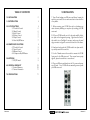
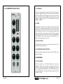
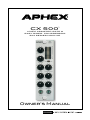
CX 500
™
LOGIC ASSISTED GATE &
EASY RIDER® COMPRESSOR
500 SERIES MODULE
Owner’s Manual
SAFETY DECLARATIONS
WARNING: Do not place objects containing liquid on this unit as
it is not designed to protect against spillage. Do not expose this
unit to dripping or splashing of liquids as the unit is not designed
to protect against these occurrences.
WARNING: The CX 500 has been tested and meets the FCC, CE
and European Union rules, regulations, and guidelines for use. Do
not attempt to modify or change the CX 500, as this could void the
regulatory compliance, which would place you at risk of losing your
authority to operate the CX 500.
WARNING: Do not place objects on top of this unit if they weigh
more than 10 pounds.
Page 2
SAFETY DECLARATIONS
This equipment has been tested and found to comply with the limits
for a Class B digital device, pursuant to part 15 of the FCC rules.
These limits are designed to provide reasonable protection against
harmful interference in a residential installation. This equipment
generates, uses and can radiate radio frequency energy and, if not
installed and used in accordance with the instructions, may cause
harmful interference to radio communications. However, there is
no guarantee that interference will not occur in a particular installation. If this equipment does cause harmful interference to radio
or television reception, which can be determined by turning the
equipment off and on, the user is encouraged to try to correct the
interference by one or more of the following measures.
1. Reorient or relocate the receiving antenna.
2. Increase the separation between the equipment and receiver.
3. Connect the equipment into an outlet on a circuit different from
that to which the receiver is connected.
4. Consult the dealer or an experienced radio/TV technician for help.
Page 3
TABLE OF CONTENTS
1.0 INSTALLATION 1.0 INSTALLATION
5
2.0 INTRODUCTION
6
3.0 GATE FUNCTIONS
3.1 Threshold Control
3.2 Attack Control 3.3 Hold Control
3.4 Release Control 3.5 Depth Control
3.6 Gate On/Off Button 4.0 COMPRESSOR FUNCTIONS
4.1 Threshold Control
4.2 Speed Control
4.3 Output Control
4.4 Compressor On/Off Button
6
6
6
7
7
7
7
5.0 METERING
5.1 GR/PK Switch
9
9
6.0 SERVICE & WARRANTY
6.1 Limited Warranty 6.2 Service Information 10
10
11
7.0 SPECIFICATIONS
11
Page 4
8
9
9
9
9
1. Turn off and unplug your 500 series rack frame. Inspect the
card slot you intend to use to make sure that it is clean and free
of any debris.
2. Before removing your CX 500 from its box, discharge any
static electricity buildup you may have by touching your 500
series rack.
3. Pull your CX 500 module out of its box and carefully slide it
into place in the designated opening. Sight down the back of
the module (use a flashlight if necessary) and ensure the card
edge connector is aligned to seat into the card slot of the frame.
4. Firmly and evenly push the CX 500 module into place until it
is positively seated in the card slot.
5. Use the 2 thumb screws in the module to mount the CX 500
front panel to the 500 series rack. These screws have a pretty
tight fit; please be careful not to cross thread.
6. Plug your 500 series rack back into the AC source and power
up your rack. Your CX 500 will automatically power up with
your 500 series rack.
Page 5
2.0 INTRODUCTION
Many other products combine a compressor and gate, but there
are problems making them work together. That’s because the compressor’s release occurs during the gate’s closure. The gate is trying
to reduce the signal level while the compressor is trying to raise it.
The compressor’s gain release counter-effects (fights against) the
gate.
3.3 HOLD
Range: 5mS to 500mS. Balance HOLD with RELEASE to obtain
the best gating effect. Usually a longer hold time allows you to use
a shorter release time. This can help when gating repetitive sounds
like drums. The gate can be held long enough to transition the
beats, and then a faster release can gate out the rumble and noise
more effectively. The HOLD setting should always be at least equal
to the ATTACK setting to insure the logic properly assists the attack
function.
The Aphex Easyrider® Compressor is gain locked whenever the
Logic-Assisted Gate activates. This holds the compression gain
constant until the gate again opens, when compression is instantly
returned to active duty and continues seamlessly. Gating and Compression happily work together! Even if the GATE DEPTH is set for
zero, the compression gate will operate as indicated by the threshold LED LOGIC ASSISTED GATE (Patent #5,334,947)
3.4 RELEASE
The CX 500 features the award-winning Aphex Logic-Assisted Gate
technology that has been so widely acclaimed since its first introduction with the Aphex Model 612 Expander/Gate. It never hesitates or chatters. Once triggered, even by a microscopic transient,
it progresses fully through the attack, hold, and release sequence.
Range: 2 to 80dB. Sets the maximum amount of gain reduction
the gate will generate. At 80dB, the gate is virtually a switch. The
audio will gate completely off. Less depth will allow the gate to
reduce the signal but not necessarily cut it off. The best setting is
one that reduces the unwanted noises just enough to be useful.
Deep gating can sometimes be apparently extreme, making the
sound seem chopped, especially with high background noise levels
when the track is naked. Gated tracks added to a mix will have their
gating effects masked by other tracks, allowing deeper gating to be
used in many cases
3.0 GATE FUNCTIONS
3.1 THRESHOLD
Range: -60 to +20dB. Adjust to reliably open the gate (let sound
through) but reject unwanted background noise. The Gate can be
effectively turned off by turning the threshold all the way to -60dB.
3.2 ATTACK
Range: 100mS to 1S. Causes the gate to close (stop audio) very
abruptly to very softly. This should be set to bring the best gating
effect to the kind of sound you have.
3.5 DEPTH
3.6 GATE ON/OFF BUTTON
Pressing the Gate button in will light the button and the Gate function will be active. Pushing it again deactivate the Gate function
and the button will not light.
Range: 4uS to 100mS. Set to the fastest setting that does not cause
a noticeable click when the gate opens. Slower settings may be
useful for effects.
Page 6
Page 7
4.0 COMPRESSOR FUNCTIONS
4.1 THRESHOLD
When the input signal level exceeds the thresh- old setting, the
compressor engages. Turning the knob counterclockwise lowers the
threshold so that compression begins at a lower input level. Turning
the knob clockwise raises the threshold so that compression only
happens at higher input levels. The threshold can be set from
-20dBu to +30 dBu.
4.2 SPEED
The Easyrider Compressor has a complex set of time constants that
adapt to the sound wave characteristics. The base time constant
can be set by the user with the Speed control. This can be looked
at like the release time control on other compressor/limiters. With
faster speed (shorter release time) the audio will be more aggressively compressed and you will hear the sound becoming busier and
fatter. Regardless of the Speed setting, the automatic time constants are working, just faster or slower.
4.3 OUTPUT KNOB
The Output level knob determines the overall output level of the
module and drives the VU meter.
4.4 COMPRESSOR ON/OFF BUTTON
This button turns the compressor function on and off. When on the
button will light up.
5.0 METERING
5.1 GR/PK SWITCH
When this switch is set to GR (Gain Reduction) the two-color
bargraph indicates both compression and gating. Compression
is shown as a green down-going bar while gating drives one red
bar downwards. When the switch is set to PK the meter becomes
an output PEAK meter. The meter will indicate output levels from
-16dBu to +21dBu.
Page 8
Page 9
6.0 SERVICE & WARRANTY
6.1 LIMITED WARRANTY
PERIOD
Two years from date of purchase.
SCOPE
All defects in workmanship and materials. The following are not covered:
a. Voltage conversions.
b. Units on which the serial number has been defaced, modified, or removed
c. Damage or deterioration:
1. Resulting from installation and/or removal of the unit.
2. Resulting from accident, misuse, abuse, neglect, unauthorized product modification or failure to follow instructions contained in the User’s Manual.
3. Resulting from repair or attempted repair by anyone not authorized by Aphex.
4. Occurring from shipping (claims must be presented to shipper).
WHO IS PROTECTED
This warranty will be enforceable by the original purchaser and by any subsequent
owner(s) during the warranty period, so long as a copy of the original Bill of
Sale is submitted whenever warranty service is required.
WHAT WE WILL PAY FOR
We will pay for all labor and material expenses for covered items. We will pay
return shipping charges if the repairs are covered by the warranty.
LIMITATION OF WARRANTY
No warranty is made, either expressed or implied, as to the merchantability
and fitness for any particular purpose. Any and all warranties are limited to
the duration of the warranty stated above.
EXCLUSION OF CERTAIN DAMAGES
Aphex’s liability for any defective unit is limited to the repair or replacement
of said unit, at our option, and shall not include damages of any other kind,
whether incidental, consequential, or otherwise.
Some States do not allow limitations on how long an implied warranty lasts
and/or do not allow the exclusion or limitation of incidental or consequential
damages, so the above limitations and exclusions may not apply to you.
6.2 SERVICE INFORMATION
If it becomes necessary to return this unit for repair, you must first contact
Aphex for a Return Authorization (RMA number), which will need to be
included with your shipment for proper identification. If available, repack
this unit in its original carton and packing material. Otherwise, pack the
equipment in a strong carton containing at least 2 inches of padding on
all sides. Be sure the unit cannot shift around inside the carton. Include a
letter explaining the symptoms and/or defect(s). Be sure to reference the
RMA number in your letter and mark the RMA number on the outside of the
carton. If you believe the problem should be covered under the terms of the
warranty, you must also include proof of purchase. Insure your shipment and
send it to APHEX at the address provided with the RMA.
7.0 SPECIFICATIONS
OPERATING LEVEL
Switch Setting:
CONNECTOR PINOUT
+4dBu
INPUT
Type:
Impedance:
Unbalanced:
Nominal Level: Maximum
Level:
CMRR:
Transformerless, active balanced
40KΩ
20KΩ
+4dBu
+24dBu
>40dB
OUTPUT
Impedance:
Nominal Level:
Maximum Level:
AUDIO
Frequency Response:
Dynamic Range:
THD:
IMD:
110Ω
+4dBu
+24dBu Unloaded
+0.5dB 10Hz-38KHz
120dB
10Hz - 22kHz @ max output
.0003%
10Hz - 22kHz 0 max output,
.0007%
1
CHASSIS GROUND
2
OUTPUT + (+4 LEVEL)
3
(unused)
4
OUTPUT - (+4 LEVEL)
5
COMMON
6
LINK
7
(unused)
8
INPUT- (+4 LEVEL)
9
(unused)
10
INPUT+ (+4 LEVEL)
11
(unused)
12
+16VDC
13
POWER SUPPLY COMMON
14
-16VDC
15
(unused)
This warranty gives you specific legal rights, and you may also have other
rights which vary from State to State.
Page 10
Page 11
PO Box 711674 Salt Lake City, Utah 84171 USA
PHONE: 801.699.2272 FAX: 435.604.7409
www.APHEX.com
Page 12