1
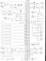
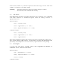
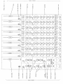
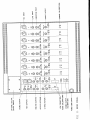
CONTENTS
1
INTRODUCTION
2
PRECAUTIONS
3
3.1
3.2
3.3
3.4
3.5
3.6
3.7
3.8
3.9
3.10
3.11
3.12
INSTALLATION
AC Mains Supply
Mic Inputs
Line Inputs
Insertion Points
Direct Outputs
Main Stereo Outputs
Monitor Outputs
Aux Outputs
Stereo 2T Return
Effects Returns
Link Inputs and Outputs
Headphone Outputs
4.22 Calibration
4
4.1
4.2
4.3
4.4
4.5
4.6
4.7
4.8
4.9
4.10
4.11
4.12
4.13
4.14
4.15
4.16
4.17
4.18
4.19
4.20
4.21
4.22
4.23
4.24
4.25
OPERATION
Channel Section
Mic/Line Selection
Phantom Power
Input Gain Control
Phase Reverse
High Pass Filter
Equalisation
Aux Sends
Pan Control
Mute Switch
PFL Switch
Channel Fader
Drive and Peak LEDs
Insertion Point
Direct Output
Master Section
Stereo Mix
Aux Masters
Effects Returns
Monitor & Headphone Level
PFL Balance Level
2T Return
Loudspeaker Mute
Metering
Digital Output Option
4.26
4.27
4.28
4.29
4.30
4.31
Bit Rate Select
Sampling Frequency Select
Digital Output Meter
Lock Status
Output Formats
Wordclock Input
5
USER TIPS / FAQs
6
SERVICE
7
SPECIFICATIONS
1
INTRODUCTION
Congratulations on purchasing the TL Audio M-3 TubeTracker 8/2 Valve Mixer. The
M-3 combines classic valve techniques with low noise solid-state circuitry to produce
a unit offering high specification signal paths with the unique sound of valves. 8 input
channels are provided, all with mic and line inputs, 48V phantom power (selected via
a single switch in the master section), four band EQ, 2 aux sends, pan and 100mm
fader. Mixing is via balanced busses to valve mix amplifiers. The stereo output is also
controlled by 100mm faders, and monitored by illuminated moving coil VU meters.
Each channel features a direct output, configurable for +4dBu or -10dBu nominal
level. Two stereo effects returns and a two-track monitoring facility complete the
audio connections, also featuring +4dBu / -10dBu switching.
The number of channels may be extended by the link facility, which enables any
number of mixers to be daisy-chained together. Comprehensive monitoring is
provided on dedicated outputs, with automatic PFL switching, stereo return and
headphone output. Typical applications include direct to stereo recording, use as 8
channel outboard EQ during mixdown, and as a complete studio, stage or PA mixer.
The mixer is 10U high, and may be housed in a 19” rack or tabletop mounted using
the supplied wooden trim. A separate, fully regulated DC power supply and cable is
included with the mixer. The PSU is also 19” rack mounting and occupies 2U of rack
space.
The block diagram of the M-3 TubeTracker is shown in fig.1. A solid state,
electronically balanced input amplifier is used, to achieve state of the art performance
with very low noise, low distortion and wide bandwidth. The mic input is via an XLR
socket and is suitable for low impedance (150-600 ohm) microphones, with a gain
control range of +16 to +60dB. A front panel switch selects 48V phantom power. The
line input has an effective overall gain range of -20 to +20dB, allowing the valve
stages to be fully driven from line level signals in the range -20 to +20dBu. The input
stage is directly coupled to a second stage triode valve amplifier. Increasing the gain
at the input stage allows the unique overdriven valve sound to be gradually
introduced, as indicated by the “Drive” and “Peak” LEDs.
An insertion point is provided, pre-EQ, providing a means of connecting external
equipment (a compressor, for example) into the channel.
The equaliser section provides shelving LF and HF filters, followed by swept
frequency low-mid and high-mid peaking filters. The EQ stages may be bypassed for
easy A-B comparison.
Mixing to the stereo buss is via a pan control and 100mm fader. PFL and channel
MUTE switches are also provided. Two Aux sends are also available, Aux 1
switchable pre or post fade, and Aux 2 permanently post fade.
After the buss mix amplifiers (which incorporate a triode valve stage), the link inputs
are also added, allowing expansion to any number of channels. The stereo outputs are
controlled by long throw faders, and interfaced via electronically balanced, earth free
solid state output drivers.
The monitoring outputs normally follow the stereo output, but may be switched to the
2 track return inputs, to check recording onto tape, for example. Any PFL signal
automatically over-rides the monitor output. The monitor level and relative PFL level
are individually controlled.
Dual moving coil VU meters follow the monitor outputs. The meters are factory set
for 0dB indication = +4dBu, but may be recalibrated using trimpots accessable from
the rear panel.
The Aux outputs are controlled by master level controls, and two stereo effects returns
provide line level inputs, with gain and balance controls. Rear panel switches allow
these signals to be set for +4dBu or -10dBu nominal operating level.
Please read this manual fully before installing or operating the M-3 mixer.
2
PRECAUTIONS
As with all electrical equipment, care must be taken to ensure reliable, safe operation
of your mixer. The following points should always be observed:
- All mains wiring should be installed and checked by a qualified
electrician,
- Ensure the correct operating voltage is selected on the power supply
before connecting to the mains supply,
- Connect the power supply to the mixer before switching on,
- Never operate the mixer or power supply with any cover removed,
- Do not expose to rain or moisture, as this may present an electric
shock hazard,
- Replace the fuses with the correct type and rating only,
- Refer any service requirement to qualified personnel.
Warning: This equipment must be earthed.
Caution: Ensure adequate ventilation of the power supply and mixer.
3
INSTALLATION
3.1
AC Mains Supply.
The mixer includes a separate T L Audio VR150 power supply, which provides fully
regulated DC outputs for the valve HT and heaters, phantom power and solid-state
circuitry. It is essential that the mixer is only powered from a TL Audio VR150
supply.
The mixer may be mounted in a standard 19” rack, occupying 10U of space. Adequate
ventilation must be provided, with free space or vent panel immediately above and
below the mixer ventilation slots. Alternatively, the mixer may be table-top mounted,
in which case it must be placed on a firm, flat surface which will not obstruct the air
flow through the ventilation slots. The wood trim included with the mixer may be
fitted if required. In both rack and tabletop applications, care must be taken to provide
a solid support for the mixer and the cables that will be connected to it.
The power supply is fitted with an internationally approved 3-pin IEC connector. A
mating socket with power cord is provided with the unit, wired as follows:
Brown: Live.
Blue:
Neutral.
Green/Yellow: Earth (Ground).
All mains wiring should be performed by a qualified electrician with all power
switched off, and the earth connection must be used.
The power supply generates a certain amount of heat during use, which must be
allowed to dissipate from the ventilation slots. The supply includes a low noise, slow
speed DC fan, drawing air in from the rear of the unit and exhausting from the front
vents. Never cover the power supply or locate it near a source of heat, for example a
radiator or power amplifier.
The power supply should be connected to the mixer with the multi core cable
supplied, before connecting the supply to the mains. The connectors should be
inserted and secured into place by tightening the locking rings. The cable is specially
selected for the high voltage and current requirements. Do not substitute any other
cable or attempt to extend the cable supplied.
Before connecting the power supply to the mains, check that the voltage selector
switch on the rear panel is correctly set. The unit may be set for 115V (accepting
voltages in the range 110V to 120V, 60Hz AC), or to 230V (for voltages in the range
220V to 240V, 50Hz AC). The fuse required is 20mm anti-surge, 2AT for 230V rated
voltage or 3.15AT for 115V rated voltage.
Warning:
3.2
attempted operation on the wrong voltage setting, or with an
incorrect fuse, will invalidate the warranty.
Mic Inputs.
Each channel has a female, 3-pin XLR connector for mic connection. It is compatible
with either balanced or unbalanced signals, when the mating connector is
appropriately wired:
Balanced inputs:
- Pin 1 = Ground (screen).
- Pin 2 = Signal Phase (“+” or “hot”).
- Pin 3 = Signal Non-Phase (“-” or “cold”).
Unbalanced inputs:
- Pin 1 = Ground (screen)
- Pin 2 = Signal Phase (“+” or “hot”).
- Pin 3 = Signal Ground
When using unbalanced signals, the signal ground may be obtained by linking pins 1
and 3 in the mating XLR connector. Good quality screened cable should be used,
particularly for microphone or low level sources, to prevent hum or noise pickup.
3.3
Line Inputs.
A 3 pin, 0.25” jack plug is required, which is also compatible with balanced or
unbalanced sources, when wired as follows:
Balanced inputs:
- Tip = Signal Phase (“+” or “hot”),
- Ring = Signal Non-Phase (“-” or “cold”),
- Screen = Ground.
Unbalanced inputs:
- Tip = Signal Phase (“+” or “hot”),
- Ring = Ground,
- Screen = Ground.
3.4
Insertion Points.
The insertion points are also interfaced via a 3 pin, 0.25” switched jack socket on the
rear of the unit. The pin connections are:
- Sleeve = Ground,
- Tip = Send,
- Ring = Return.
The insertion point is unbalanced. If used as an additional send only (e.g. as a send to
a tape machine or monitor mixing desk), the Tip and Ring should be wired together, to
preserve the signal path through the insertion point.
3.5
Direct Outputs.
The Direct Output connector is a 3 pin, 0.25” jack socket on the rear of the unit. The
output automatically adjusts for balanced or unbalanced connection, and may be set
for +4dBu (switch out) or -10dBu (switch in) nominal level.
The mating connector should be wired as follows:
Balanced outputs:
- Tip = Signal Phase (“+” or “hot”),
- Ring = Signal Non-Phase (“-” or “cold”),
- Screen = Ground.
Unbalanced outputs:
- Tip = Signal Phase (“+” or “hot”),
- Ring = Ground,
- Screen = Ground.
3.6
Main Stereo Outputs.
The main outputs are via balanced, 3 pin male XLR connectors.
connectors should be wired as follows:
The mating
- Pin 1 = Ground (screen),
- Pin 2 = Signal Phase (“+” or “hot”),
- Pin 3 = Signal Non-Phase (“-” or “cold”).
If an unbalanced output is required, pins 1 and 3 should both be connected to ground.
3.7
Monitor Outputs.
The monitor outputs are via balanced, 3 pin jack connectors. The mating connectors
should be wired as follows:
- Sleeve = Ground (screen),
- Tip
= Signal Phase (“+” or “hot”),
- Ring
= Signal Non-Phase (“-” or “cold”).
If an unbalanced output is required, the sleeve and ring should both be connected to
ground.
3.8
Aux Outputs.
The Aux outputs are also via balanced, 3 pin jack connectors. The mating connectors
should be wired as follows:
- Sleeve = Ground (screen),
- Tip
= Signal Phase (“+” or “hot”),
- Ring
= Signal Non-Phase (“-” or “cold”).
If an unbalanced output is required, the sleeve and ring should both be connected to
ground. The Aux outputs may be set to +4dBu or -10dBu nominal level.
3.9
Stereo 2T Return.
A stereo input is provided to the monitor section, to allow off-tape monitoring, etc.
The inputs are via balanced, 3 pin jack connectors. The mating connectors should be
wired as follows:
- Sleeve = Ground (screen),
- Tip
= Signal Phase (“+” or “hot”),
- Ring
= Signal Non-Phase (“-” or “cold”).
If an unbalanced signal is used, the sleeve and ring should both be connected to
ground. These inputs may also be set to +4dBu or -10dBu nominal level.
3.10
Effects Returns.
Two stereo inputs are provided, for effects returns or other line level sources. The
connectors are 3 pin jack sockets, and the mating connectors should be wired as
follows:
- Sleeve = Ground (screen),
- Tip
= Signal Phase (“+” or “hot”),
- Ring
= Signal Non-Phase (“-” or “cold”).
If unbalanced signals are used, the sleeve and ring should both be connected to
ground. These inputs may also be set to +4dBu or -10dBu nominal level. A single
mono source can be connected to each effects return by plugging into the left input
only. The M-3 will automatically feed this mono signal equally to both left and right
channels, thus removing the need for a split cable.
3.11
Link Inputs and Outputs.
The link facility allows two or more mixers to be “daisy-chained” together, to increase
the number of input channels. The stereo outputs, aux mixes and PFL busses are all
connected when mixers are linked, with the master controls on the last (“master”)
mixer controlling the outputs (see fig. XX.). The output faders and aux masters on the
other (“slave”) mixers do not effect the output level from the master, but continue to
control their own outputs, which may be used as sub-group outputs.
The link connectors are 15 pin “D” type connectors, with locking posts. The cable
used to link mixers together should connect pins 2 to 15 straight through. All of the
audio connections on the link connectors are balanced, and the PFL control signal is
optically isolated. Pin 1 is an overall ground connection, which should be connected to
the cable screen.
3.12
Headphone Outputs.
The front panel jack socket is suitable for driving headphones of 32 ohms or higher
impedance. A standard 0.25” jack plug should be used.
3.13
Calibration.
Various calibration trims are accessible from the rear panel. The “+10dB” and “0dB”
trims should only require adjustment if a valve or fader is replaced. The “Meter” trims
may be used to re-adjust the calibration of the VU meters if a setting other than 0VU =
+4dBu is required.
The rear panel connectors are identified in fig. 2.
4
OPERATION
4.1
Channel Section.
The front panel controls for a channel are identified in fig. 3.
4.2
Mic/Line Selector.
Ensure that the correct input connector, mic or line, is being used and that the front
panel ‘LN’ switch is set to the appropriate position. In the ‘up’ position the mic input
is selected: depressing the LN switch selects the line input as the source. Note that
both mic and line inputs may be connected at the same time, but only one is selected.
When recording microphones via the M-3’s direct outputs to an 8 track recorder, it is
possible to connect the recorder outputs back to the line inputs of the M-3, thus
making the line inputs function as ‘tape returns’. Once the recording has been made
selecting the line input as the source will then enable the off-tape signal to be
monitored, but care must be taken that the recorder is not in ‘input’ or ‘record-ready’
modes, otherwise a feedback loop will be created through the recorder and mixer. This
technique is useful purely as a means for checking off-tape signals, since the fader and
EQ settings applied to the source will automatically affect the playback signal as well.
4.3
Phantom Power.
+48V phantom power is available at the mic socket, controlled by a switch in the
master section and signalled by a red LED. This switch applies +48V simultaneously
to all 8 mic inputs, but will not damage any dynamic mics connected providing they
are wired correctly as per section 3.2.
CAUTION: Operation of the phantom power switch, or plugging a microphone in
with phantom power applied, may cause a click or thump in your loudspeakers. To
prevent this happening, ensure that the channel level control and stereo faders are set
to minimum before operating the switch or plugging in a microphone. Switching
between mic and line at very high input gain settings may also cause an audible thump
if the level control is not turned down.
4.4
Input Gain Control.
The gain control should be set to obtain the best signal to noise ratio, whilst preserving
adequate headroom. Note that there is 44dB variation from fully anticlockwise to
clockwise of the gain control, so any changes should be gradual to avoid sudden
overload or severe distortion. The line input accepts a wide variety of signals down to
a nominal level of -10dB, where the 20dB gain available ensures that the valve stages
can be fully driven when required. However, this large amount of gain should be used
sparingly on higher level inputs, to avoid an increase in the noise floor and
introduction of distortion.
4.5
Phase Reverse.
The phase reverse switch is used to invert the phase of the input signal and is active on
both mic and line inputs. This could be required when processing a signal that is out of
phase with other signals in a mix, in which case the resultant phase error typically
appears as a loss of low frequency signal content, due to cancellation of out of phase
components. If the M-3 is used in a multi-microphone recording situation then some
phase cancellation may occur between certain microphones, which the phase reverse
switch will correct.
4.6
High Pass Filter.
The high pass (low cut) filter is a second order circuit (12dB per octave), with the 3dB point at 90Hz. Like the phase reverse switch, the high pass filter is active on both
mic and line inputs, and is ideal for removing unwanted LF content from the input
signal. Examples would be foot noise and traffic rumble being picked up by a
microphone, or excessive low frequency response from a close mic’d source (known
as the proximity effect). The filter is bypassable for easy A/B comparison.
4.7
Equalisation.
Before switching the EQ into circuit, it is advisable to set the cut/boost controls to
their centre, or flat, position. The EQ is brought into circuit with the “EQ” push
switch, signalled by a green LED.
Each channel has four bands of equalisation: shelving low frequency (LF), peaking
low-mid (LM), peaking high-mid (HM) and shelving high frequency (HF).
The LF shelf operates at a frequency of 80Hz, while the HF shelf is set at 12kHz. The
EQ slopes have a second order 12dB/octave response, and an associated gain control
on both bands provides up to 15dB of cut or boost on each selected frequency,
controlling the full range of frequencies below the LF corner frequency and above the
HF corner frequency.
Both mid bands have a fixed Q of 0.7 (which corresponds to a bandwidth of around
1.5 octaves) allowing +/- 15dB cut or boost over a moderately broad band of
frequencies. The centre frequency is selected via the dedicated variable frequency
control, and the required amount of cut or boost is applied using the associated gain
control. The range of frequencies selectable is 50Hz to 2kHz on the LM band, and
500Hz to 18kHz on the HM band, giving a wide spread of frequencies with good
overlap in the 500Hz to 2kHz region.
4.8
Aux Sends.
The channel is equipped with two aux sends (set post EQ), normally used to either
feed FX devices or as headphone cue sends.
Aux 1 is switchable pre or post fade from the front panel, whist Aux 2 is permanently
connected post fade.
4.9
Pan Control.
The pan control positions the image within the stereo field, from fully left in the anticlockwise position, through centre at the detented position to fully right in the
clockwise position. The gain law is -3dB at the centre.
4.10
Mute Switch.
The channel may be muted or switched on without affecting the level set on the
channel fader. Red LEDs indicate which channels are currently muted.
4.11
PFL Switch.
When PFL, or pre-fade listen, is accessed, a red LED illuminates on the channel (or
channels) selected, and also on the master section of the mixer. PFL allows the signal
present on the channel to be monitored before the channel fader is opened and the
signal connected to the main output.
4.12
Channel Fader.
A 100mm fader is located at the bottom of the channel, and sets the level of that
channel’s signal that is fed into the stereo mix buss. The fader provides +10dB of gain
at its maximum position.
4.13
Drive and Peak LEDs.
The yellow Drive LED provides a visual indication of the signal level through the
input valve stage, and therefore the extent of “warming” or valve character being
introduced. The drive LED will gradually illuminate as the input level or gain is
increased, over the range +6dBu to +16dBu.
The red Peak LED operates as a conventional warning that clipping is about to occur.
The operating level of both input and post fader stages is monitored, and the LED
illuminates at a threshold of +21dBu, when there is less than 5dB of headroom
remaining to the direct output.
Normal operation would be to set the input gain so that the Drive LED is illuminating
regularly, with occasional illumination of the Peak LED occurring on loud transients.
4.14
Insertion Point.
The channel insertion point is configured pre EQ, where it may be used to insert a
compressor or other signal processor into the channel path.
4.15
Direct Output.
The channel direct out may be used to feed a multitrack recorder while simultaneously
obtaining a live or monitor stereo mix, making the M-3 ideal for the tracking of voices
and instruments. It also allows the mixer to be operated as 8 independent channels, for
example as outboard EQ inserted into a larger console. The direct output is configured
post fader, allowing the channel fader to control the level being fed through to the
output. An operating level switch is provided adjacent to the rear panel connector,
which selects whether the direct output functions at -10dB or +4dB, allowing easy
interfacing with all types of equipment.
4.16
Master Section.
The controls for the M-3 master section are shown in Fig. 3.
4.17
Stereo Mix.
A single 100mm long throw fader allows accurate control of the stereo mix output
level. The stereo mix will include the link inputs, which are provided to connect
multiple M-3s together (see section 3.11).
4.18
Aux Masters.
Each aux send features a rotary master level control, which governs the overall level
from the aux output. An associated PFL switch allows each aux send to be auditioned
in isolation, by placing the aux signal (pre the master level control) on the PFL buss.
An operating level switch is provided adjacent to the rear panel connector which
selects whether each aux send functions at -10dB or +4dB, allowing easy interfacing
with all types of equipment.
4.19
Effects Returns.
The two stereo effects returns are each equipped with a rotary fader and a L/R balance
control. Both returns are fed directly into the stereo mix. A PFL switch allows each
return to be auditioned in isolation. A mono signal can be fed to either of the returns
by connecting it to the left hand return input only. This will automatically feed the
mono signal equally to both left and right hand sides of the stereo buss
simultaneously.
An operating level switch is provided adjacent to the rear panel connector which
selects whether each aux return functions at -10dB or +4dB, allowing easy interfacing
with all types of equipment.
The effects returns are typically used to feed the outputs of FX devices back into the
stereo mix, adding ‘wet’ signal to the ‘dry’ stereo mix. However, the returns can also
be used as simple extra line inputs for signals that require no EQ or FX to be added to
them via the mixer.
4.20
Monitor & Headphone Level.
The M-3 provides a stereo monitor output, for connection to a power amplifier and
monitor loudspeakers, plus a front panel headphone output. The Monitor level control
governs the level of signal fed to both these outputs.
The monitor signal normally follows the main stereo output, but will automatically
switch over to the PFL buss whenever any PFL button is pressed, this condition being
indicated by a red LED. Similarly, the monitor signal will follow the 2T return when
the 2T return switch is activated in the master section.
4.21
PFL Balance Level.
The PFL Balance control allows adjustment of the PFL signal level relative to the
main stereo monitor level, as the PFL signal could be considerably louder than the
stereo output, depending on the mix.
4.22
2-T Return.
When recording the stereo mix output onto DAT or CD-R, for example, it is
sometimes useful to be able to monitor the output from the mastering machine, in
place of the mixer stereo output, as confirmation that the signal is actually being
recorded (this is particularly useful when using a four-headed DAT machine or a three
-headed analogue 2T machine, since the off-tape signal can be monitored). This is
achieved by selecting the 2T Return switch near the monitor level control. This
facility may also be used for playback after recording.
4.23
Loudspeaker Mute.
This switch mutes the rear panel monitor output. This is particularly useful when
using headphones, enabling the main monitors to be muted without needing to turn off
their amplifiers. This is also useful for temporarily muting the monitors without
needing to alter any fader levels, for instance during a telephone call.
4.24
Metering.
Two illuminated VU meters on the M-3 normally monitor the main stereo output, but
will automatically switch to monitor the PFL buss when any PFL switch is engaged.
Similarly, when the 2T return is selected as the monitor source (via the relevant select
switch - see section 4.22) the meters will automatically switch to monitor the 2T
return.
The meters are calibrated to indicate 0VU when a signal level of +4dBu is generated
at the main outputs. The meter reference level may be changed via the two adjustment
trimmers (labelled Meter L and Meter R) on the rear panel - using a small screwdriver.
A pair of red Peak LEDs operate on the stereo buss as a conventional warning that
clipping is about to occur. The LEDs illuminate at a threshold of +21dBu, when there
is less than 5dB of headroom remaining on the main outputs. Normal operation would
be to set the stereo buss fader levels so that occasional illumination of the Peak LEDs
occurs on loud transients.
4.25
Digital Output Option.
The M-3 supports an optional digital output card (DO-1) that is fitted via the rear
panel. The DO-1 card provides simultaneous AES/EBU, SPDIF and TOSLINK optical
outputs, plus a Wordclock input. The master section of the M-3 provides front panel
control of the bit rate and sample rate, plus an LED indication of external lock and a
bargraph meter monitoring digital output level. These related front panel controls and
meters will have no effect until the DO-1 card is fitted.
The DO-1 enables the M-3 to directly interface with digital equipment that carries
these same format inputs, thus bypassing any A/D input stage.
4.26
Bit Rate Select.
A three position rotary switch enables the user to select whether a 16, 20 or 24 bit
word length is outputted by the DO-1’s digital outputs. The output is properly dithered
to the selected word length.
4.27
Sampling Frequency Select.
The DO-1 card is capable of generating a digital output at four different sampling
rates: 44.1, 48, 88.2 and 96kHz. These rates are selectable via a four position rotary
switch on the M-3 front panel.
4.28
Digital Output Meter.
The output level generated by the DO-1 card is monitored via an 8 segment LED
ladder that registers levels from ‘SIG’ (signal present) through to digital CLIP, which
corresponds to a 0dBFS level sustained for several consecutive samples. Both left and
right channels are monitored and the meter registers the higher of the two.
4.29
Lock Status.
The Lock LED will illuminate when the M-3 is locked to an external clock source
connected via the rear panel Wordclock input, assuming that the rear panel switch is
set to ‘External’ and the correct sample rate is selected (see section 4.26). At all other
times the M-3 will be synced to its own internal clock.
4.30
Output formats.
The DO-1 card offers three separate output formats, all of which are active
simultaneously:
AES/EBU - a balanced pro format on 3 pin XLR, conforming to AES3 and IEC609584 standard.
SPDIF - an unbalanced coaxial consumer style format on RCA phono, conforming to
IEC60958-3 standard.
Optical - offers an optical version of the SPDIF format on a TOSLINK optical
connector, with data conforming to IEC60958-3 standard.
4.31
Wordclock Input.
A rear panel Wordclock Input is provided for connecting the M-3 to an external
master clock source. An associated switch on the rear panel selects between external
synchronisation and internal clock. In external mode the front panel sample rate
selection switch is still active and needs to be set to match the frequency of the
incoming wordclock source.
The Wordclock input connector is a BNC-type terminated in 75 ohms.
5
USER TIPS AND FAQs
Q:
Is there any way of making the channel direct outputs pre EQ and pre
fader?
No, but you can use the channel insert points to feed a multitrack recorder, and
these are both pre EQ and pre fader. Just connect the ‘send’ of the M-3 insert
point to the tape machine input, and ensure that the tip and ring of the insert
cable are connected together to maintain signal flow through the channel (see
section 3.4).
A:
Q:
A:
Suppose I want to patch a compressor or EQ into the M-3 stereo mix
buss?
There are no master insert points on the M-3, but you can connect
outboard devices to the M-3 master XLR outputs. Simply patch the required
outboard between the M-3 outs and the inputs of your mastering machine,
using the M-3 2-T return to listen to the processed stereo signal. This also has
the advantage of using balanced connections, rather than unbalanced mix buss
insert points.
Q:
A:
How many valve stages are in the M-3?
Each channel utilises one triode valve stage in the preamp stage - this comes
just after the 90Hz filter section, so is active on both mic and line inputs. There
is also a triode valve stage in both the left and right mix busses, just ahead of
the stereo fader. All the valves are ECC83/12AX7A types, and all the valve
stages are run from a 200V DC power supply.
Q:
A:
Is it better to leave the unit switched on all the time?
Doing this will avoid the typical 30 minutes warming up period that the unit
would normally require to settle, but will reduce the lifespan of the valves
since the valve heater will be on constantly. Most users would power off
between sessions but leave a suitable warming up period before use.
Q:
A:
How long will the valves last before they need replacing?
This very much depends on whether the unit is left powered up all the time
(see above) and whether the unit is moved around and subject to vibration.
We’d say the average lifespan in a static set-up would be three to four years.
6
SERVICE
Should the mixer or power supply require service, it must be taken or posted to an
authorised dealer. Please retain the original packing for possible future use, and ensure
the unit is suitably protected during transit. The manufacturer cannot accept
responsibility for damage caused during transportation.
The mixer is supported by a limited warranty for a period of one year from the date of
purchase. During this period, any faults due to defective materials or workmanship
will be repaired free of charge. The warranty excludes damage caused by deliberate or
accidental misuse, operation on the incorrect mains voltage, or without the correct
type and value of fuse fitted. If claiming service under warranty, proof of purchase
date must be included. It is the user’s responsibility to ensure fitness for purpose in
any particular application. The warranty is limited to the original purchase price of the
equipment, and specifically excludes any consequential damage or loss.
Please record the following details:
Serial Number.............................
Date purchased...........................
Dealer.........................................