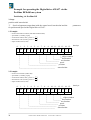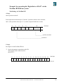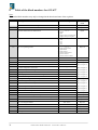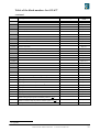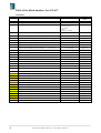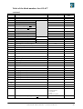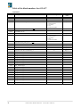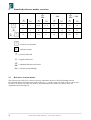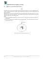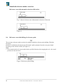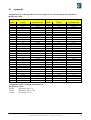
1
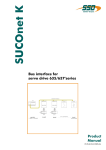
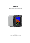
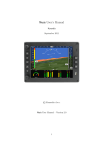
Profibus DP
EUROTHERM
DRIVES
Series
Bus interface
PRODUCT
MANUAL
Product manual Model: Profibus DP
07-05-04-02-E-V0801.doc
Further descriptions, that relate to this document
UL: 07-01-05-06
635 – Product manual
UL: 07-02-08-03
637 – Product manual
UL: 07-02-09-01
637+ – Product manual
UL: 10-06-03
Serial transfer protocol
EASY-serial - Product Description
ã EUROTHERM Drives Limited.
All rights reserved. No portion of this description may be produced or processed in any form without the
consent of the company.
Changes are subject to change without notice.
EUROTHERM has registered in part trademark protection and legal protection of designs.
The handing over of the descriptions may not be construed as the transfer of any rights.
Made in Germany, 2001
2
Product manual Model: Profibus DP
07-05-04-02-E-V0801.doc
CONTENTS
Page
The most important thing first ........................................................................................5
1
Appendix for user manual Digital drive 635/637/637+
for the bus system Profibus DP ............................................................................6
2
Basic features of the Profibus DP.........................................................................6
2.1
2.2
2.3
Device data base .................................................................................................................6
Ident number.......................................................................................................................6
Communication ..................................................................................................................6
3
Digital drive 635/637/637+ with Profibus DP......................................................7
3.1
3.2
3.3
3.4
3.5
3.6
3.7
Data length..........................................................................................................................7
Bus watching ......................................................................................................................7
Station address....................................................................................................................7
Schematic sketch ................................................................................................................7
Selection of the correct baud rate .......................................................................................8
Bus termination ..................................................................................................................9
Fieldbus diagnosis via the EASYRIDERâ shell .............................................................10
4
Definitions of the data field .................................................................................11
4.1
4.1.1
4.1.2
4.2
4.3
4.3.1.
4.4
4.4.1.
Numbers representation in the serial commands ..............................................................11
2 byte hexadecimal values (WORD) ................................................................................11
4 byte hexadecimal values (LWORD)..............................................................................11
Parameter scaling..............................................................................................................11
Contents of the control word byte 0 .................................................................................12
Inhalte des Steuerwortes Byte 1 Contents of the control word byte 1..............................12
Edge change of the control word ......................................................................................13
Move commands without edge change.............................................................................13
5
Data frames ..........................................................................................................14
5.1
5.2
5.3
5.4
5.5
5.6
5.7
5.8
5.9
5.10
Host login / logout (1/2) ..................................................................................................14
Control word "start absolut" (3) and "start incremental" (4) ...........................................14
Control word "start reference run" 1) (5) .........................................................................14
Control word "stop" (6) ....................................................................................................15
Control word "stop with braking ramp" (7).....................................................................15
Control word "preset counter" (8) ...................................................................................15
Control word "set BIAS processing pointer" (9) .............................................................16
Control word "move +" (10) and "move -" (11)..............................................................16
Control word "move synchron on" (12) ..........................................................................16
Control word "synchron setting" (13)..............................................................................17
Product manual Model: Profibus DP
07-05-04-02-E-V0801.doc
3
CONTENTS
Page
5.11
5.12
5.13
5.14
5.14.1
5.15
5.16
5.17
5.18
5.19
5.20
5.21
Control word "eyemark command 1" (14) .....................................................................17
Control word "eyemark command 2" (15) .....................................................................17
Control word "virtual axis" (16).......................................................................................18
Control word "read data block" (17) ...............................................................................18
Input data ..........................................................................................................................18
Control word "write data block" (18) ..............................................................................19
Control word reserved (19)..............................................................................................19
Control words Digital drive 635/637/637+:
"disable/ enable" (20/21) "RESET" (22) "save data" (23)...........................................19
Control word "operating mode speed loop" (24).............................................................20
Control word "write/read variable / flags" (25) ...............................................................21
Input buffer (Digital drive 635/637/637+ → master) .......................................................23
Data contents of the input buffers.....................................................................................24
6
Pin assignment bus interface Profibus DP ........................................................26
7
Example for operating the Digital drive 635/637/637 +
via the Profibus DPfield bus system..................................................................27
7.1
7.2
7.2.1
7.2.2
7.2.3
Positioning via Profibus DP .............................................................................................27
Example for control by Siemens S7 .................................................................................30
Read Data .........................................................................................................................30
Write Data ........................................................................................................................31
Watch and control variables .............................................................................................31
8
Table of the block numbers for 635 /637 ...........................................................32
9
Standard reference modes overview ..................................................................38
9.1
9.2
9.3
9.4
9.5
9.6
Reference run and modes .................................................................................................38
Reference run to the resolver zero position ......................................................................39
Reference run to the reference sensor...............................................................................40
Reference run to the reference sensor and the resolver zero position ..............................41
Reference run with automatic selection of direction ........................................................41
Reference run with shifting of reference point .................................................................42
10
Appendix...............................................................................................................43
11
Index......................................................................................................................44
12
Modification Record ............................................................................................46
4
Product manual Model: Profibus DP
07-05-04-02-E-V0801.doc
The most important thing first
We thank you for the trust that you have shown in our product.
The operating instructions presented hereserves as an overview of the technical data and features.
Please read the operating instructions before putting the product to use.
If you have any questions, please contact your nearest Eurotherm representative.
Improper application of the product in connection with dangerous voltage, can lead to injuries.
In addition, damage can also occur to motors or other products.
Therefore please observe strictly our safety precautions.
Topic: Safety precautions
We assume that as an expert, you are familiar with the relevant safety regulations, especially
in accordance with VDE 0100, VDE 0113,VDE 0160, EN 50178, the accident prevention
regulations of the employers liability insurance company and the DIN regulations and that you
can use and apply them.Also the CE - regulations are to be observed and guaranteed.
Depending on the kind of application, additional norms e.g. UL, DIN are to be observed.
If our products are employed in connection with components from other manufacturers, their
operating instructions are also to be strictly observed.
Product manual Model: Profibus DP
07-05-04-02-E-V0801.doc
5
1
Appendix for user manual Digital drive 635/637/637+
for the bus system Profibus DP
A Profibus DP module (RP_PDP) can be integrated as an option into the Digital drive 635/637/637+.
Consequently it is possible to network the Digital drive 635/637 as a slave in the Profibus DP bus system.
2
Basic features of the Profibus DP
The Profibus DP was developed for a fast data exchange. The bus access occurs between the masters (not
Eurotherm drives) in token passing mode and to the peripheral devices in the master slave mode.
The bus cycle time will be calculated exactly only in a mono master system
(only one master in the system).
A maximum of 126 participators (master and slaves) can be connected on the bus system.
2.1
Device data base
Each Profibus DP device is characterized by typical features and the efficiency on the bus. These features
are provided (according to the Profibus norm) to the user in the form of device specification sheets and a
device data base (GSD; ASCII-file).
The fixed file format facilitates the configuration of Profibus DP systems. This device master file (GSD)
comes with the EASYRIDERâ shell.
File name:
2.2
ASB_1008.GSD
Ident number
Each participator must have an individuall ident number. This make it easier to projekt the sytems and
allows the unequivocal assignment of the connected participators.
The Ident number and the device data base will be controlled by the Profibus User Organisation (PNO).
The 635/637 has following ident number:
Ident number: 1008
2.3
Communication
The maximum cable length depends on the transmission rate
(see DIN 19245-3):
187,5 kBit/s:
up to 1000 m cable length
500 kBit/s:
up to 400 m cable length
1,5 MBit/s:
up to 200 m cable length
3 MBit/s:
up to 150 m cable length
6 MBit/s:
< 150 m cable length
12 MBit/s:
up to 100 m cable length
The Digital drive 635/637 supports baud rates up to 6 Mbit/s.
With baud rates > 1,5 Mbits/s special connector plugs are to be provided.
These contain the bus termination resistors and the corresponding inductivities, in order to reduce the line
reflections.
Note:
When removing such plugs, there can be mismatches which can produce interference on the bus.
The communication occurs via the RS 485 standard. For the bus cable shoud be used a twisted pair cable
with shield.
6
Product manual Model: Profibus DP
07-05-04-02-E-V0801.doc
3
Digital drive 635/637/637+ with Profibus DP
3.1
Data length
At the Digital drive 635/637 there are configurated 16 byte for input and output data.
Byte for sign by configuration the master:
0xBF (hex)
3.2
191d
Bus watching
The Digital drive 635/637 makes it possible, to detect a bus break and to execute a definition reaction.
For that, the bus watching must be activated by the master!
Follow reaction can activate after detected a bus break:
- no reaction
- stop abrupt
- stop with braking ramp
- disable Digital drive 635/637
The selection and the setting made by the EASYRIDER shell in the menu
→ commissioning → fieldbus.
3.3
Station address
The station address will be set with
Digital drive 635/637 by DIP-switches on the interface card or by the EASYRIDER shell.
- valid address range: 2 - 125
If the station address should be set by the EASYRIDER shell, the DIL-switches must
set smaller than 2.
By the EASYRIDER shell you have to program
the address in the menu → commissioning → fieldbus.
The changed data should be stored in the EEPROM with button /.
It should be considered, that the setting of a
station address only during the initialization of the Digital drive 635/637, so after when you switch on the
power supply (24V), will be get in.
3.4
Schematic sketch
Profibus DP fieldbus
master
Eurotherm
servo drive
drive
Product manual Model: Profibus DP
Eurotherm
servo drive
drive
07-05-04-02-E-V0801.doc
7
3.5
Selection of the correct baud rate
The baud rate should always be set high enough to fulfill the required system reaction time
The lower the baud rate is selected,
- the more insensitive the system is to interference from outside.
- the less difficult it will be to repress eventual interference.
The bus cycle time depends on the set baud rate.
It should not be less than the greatest telegram update time of a slave in the system.
This allows you to prevent telegrams arriving from the bus faster than they can be processed
by the respective participant.
The update time for the 635/637 is 2 msec.
In a mono master system the system reaction time can be calculated in dependency on the selected
baudrate as following:
The theoretically system reaction time =
[token + GAP test + number of stations * offset + number of E/A-bytes * 11 + TSM] * tBit
Up to 1,5 MBit/s (all stations have inputs and outputs) and the lower limiting values according to DIN
19245-3 the cycle time can be calculated as follows:
cycle time = [70 + 403 + number of stations * 246 + number of E/A-bytes * 11 + 1 ] * tBit
Examples:
In the following, a few examples are shown of how the cycle time changes depending on the number of
participants at the same baud rate.
Useful data: 16 bytes I/O per participant
cycle time [ms]
participator
Zyklus number of the transmit i/o bytes per cycle
500 kBit/s
1,5 MBit/s
2
4
5
10
64 Byte
128 Byte
160 Byte
320 Byte
3,3 ms
5,7 ms
6,9 ms
12,9 ms
1,1 ms
1,9 ms
2,3 ms
4,3 ms
Below an extract from the DIN 19245-3 to calculate the system reaction time:
Token
GAP
Offset
TSM
:
:
:
:
TID1+ TToken
TID1 + TSD1 + TSL
TID1 + 2 * TSD2_R + min TSDR
= (37 + 33)1tBit
= (37 + 66 + 300)1tBit
= (37 + 198 + 11)1tBit
TToken : time to send a token telegram
TSD1 : time to send a telegram with Start Delimiter SD1
TID1
TSDR
TSL
TSM
1
8
: Idle Time
: Station-Delay-Time of the responder
: Slot-Time
: Safty Margin
times for 1,5 MBit/s
Product manual Model: Profibus DP
07-05-04-02-E-V0801.doc
= 70 tBit
= 403 tBit
= 246 tBit
= 1 tBit
3.6
Bus termination
For communication, a defined quiescent level must be ensured on the bus. Therefore termination
resistors must be added to the first and last participant in the bus train.
At baud rates of up to 1,5 Mbits/s, the termination resistors integrated on the interface card of the
Digital drive 635/637 can be used for one bus termination.
Both jumpers (9 and 10) are to be closed (on).
Bus plugs with integrated termination resistors can also be used.
With baud rates of > 1,5 Mbits/s special connecting plugs are to be used.
(see chapter 2.3, transmission technology)
a) 635 - plan view
b) 637 - plan view
picture 3.1
DIP switches for: - station address (1 - 8)
- termination resistors (9, 10)
Product manual Model: Profibus DP
07-05-04-02-E-V0801.doc
9
3.7
Fieldbus diagnosis via the EASYRIDERâ shell
Additionally, the EASYRIDER shell also offers an online Profibus DP diagnosis display.
Menu: → Diagnosis → Fieldbus
This display offers the following possibilities for diagnosis:
- station address
- name of drive
- bus status: connection ok/ interrupted
This allows you to detect whether communication with the master exists.
- status:
Here the internal status of the Profibus ASICs is displayed.
Here the user gets important information about the internal state machine of the Profibus ASICs.
It can be very helpful for an initial commissioning.
0x49:
0xA9:
0x05:
Master in STOP
Data exchange
Connection interrupted
All other status displays indicate incorrect parameterization of the drive with the master.
- display of the baud rate
- firmware version of the Profibus DP interface
- display of the data contents of each received telegram.
10
Product manual Model: Profibus DP
07-05-04-02-E-V0801.doc
4
Definitions of the data field
Definition of the data field in the Profibus DP fieldbus system for the Digital drive 635/637:
Output data (master → Digital drive 635/637):
16 byte data unit
0.
1.
2
2.
3.
4.
2
5.
6.
2
|
control word( see 4.3)
4.1
7.
2
8.
9.
10.
2
11.
12.
2
13.
2
14.
15.
2
(Byte)
|
parameter
Numbers representation in the serial commands
4.1.1 2 byte hexadecimal values (WORD)
Number range ±215 (signed integer)
Example: The hexadecimal value 0123h
represents itself as follows:
01 = High-Byte (Byte 1)
23 = Low-Byte (Byte 2)
Precedence within the serial command:
4.1.2 4 byte hexadecimal values (LWORD)
Number range ±231 (signed long)
Example: The hexadecimal value 01234567h represents itself as follows:
01 = High-Byte (Byte 1)
23 = Low-Byte (Byte 2)
45 = High-Byte (Byte 3)
67 = Low-Byte (Byte 4)
Precedence within the serial command:
4.2
Parameter scaling
parameter
speed
acceleration, deceleration:
scaling
value = v [rpm]
value = a [rpm/s] / 5
Product manual Model: Profibus DP
07-05-04-02-E-V0801.doc
11
4.3
Contents of the control word byte 0
HOST-login necessary
activated drive necessary
commandnumber
dec
hex
0
1
2
3
4
5
6
7
8
9
10
11
12
13
14
15
16
17
18
19
20
21
22
23
24
25
00
01
02
03
04
05
06
07
08
09
0A
0B
0C
0D
0E
0F
10
11
12
13
14
15
16
17
18
19
Edge change necessary
command description
read status
Host login
Host logout
start absolute position
start incremental position
start reference run
stop
stop (with braking ramp)
preset counter
set BIAS-processing pointer
move +
move move synchron
synchron adjustment
eyemark control 1
eyemark control 2
virtual axis
data-bloc read
data-bloc write
not used
deactivate Digital drive
activate Digital drive
reset Digital drive
store data in drive
operating mode speed (serial)
read/ write variable/ flag
4.3.1. Inhalte des Steuerwortes Byte 1
notes
attention! 2. interface login
yes
yes
yes
yes
yes
yes
yes
yes
yes
yes
yes
yes
yes
yes
yes
yes
yes
yes
yes
yes
yes
yes
yes
yes
yes
yes
yes
yes
yes
yes
yes
yes
yes
yes
yes
yes
yes
yes
yes
*)
yes
reference mode see chapter 9
only in operating-mode 5 with BIAS
status-response see command
*) and status-response see command
yes
no
yes
no
yes
yes
no
yes
yes
*)
*) edge and status-response see command
Contents of the control word byte 1
dec hex command description
0
00 read status with realposition 1
1
01 read status with realposition 2
The answer( Inputbuffer) is described in chapter 5.20
12
Product manual Model: Profibus DP
07-05-04-02-E-V0801.doc
4.4
Edge change of the control word
In installations the cycle times of the PLC and the respective bus system are often different and also
not syschronous.
In this case the following points must be observed:
With normal program processing the PLC new telegrams to the bus master at a certain time. If the
bus cycle time is now shorter than the PLC cycle time the telegrams will be sent several times
according to the bus cycle time. New telegrams are usually transferred from the PLC again once
after a further PLC cycle is ended.
Without a slope evaluation of the control words This fact would result in the commands being
executed several times.
This is, however, undesirable with some commands.
With the command "start incremental" this would result in the specified position being added to
setpoint position with every telegram received.
With telegrams with slope evaluation identical control words in sequence are only accepted once.
For an intentional repetition of a control word another control word must be sent in between. For
this the control word "0", actually not a command,can be used.
4.4.1. Move commands without edge change
As of firmwareversion 5.12 you have the possibility to send the following commands
without edge change.
HOST-login necessary
activated drive necessary
commandnumber
dec
hex
Edge change necessary
notes
command description
yes
no
parameter like command 03
46 stop
yes
no
parameter like command 06
71
47 stop (with braking ramp)
yes
no
parameter like command 07
74
4A move +
yes
yes
no
parameter like command 0A
75
4B move 4C move synchron
yes
yes
no
parameter like command 0B
yes
yes
no
parameter like command 0C
67
43 start absolute position
70
76
yes
Product manual Model: Profibus DP
07-05-04-02-E-V0801.doc
13
5
Data frames
5.1
Host login / logout
(1/2)
The most data frames are accepted by the Digital drive only after a host registration.
The host registration must only be sent uniquely to connecting the control voltage (24V).
For Host login / logout only the control word from the Digital drive 635/637 will be evaluated. The 2nd to
15th bytes can containe any data.
Only one interface will be have a login
(COM1 or COM2).
.
Send a telegramm (output data) with 01h
'Host login' in the control word to the
635/637.
0.
1.
2.
3.
4.
5.
6.
7.
8.
9. 10. 11. 12. 13. 14. 15.
data byte
01 00 xx xx xx xx xx xx xx xx xx xx xx xx xx xx
xx : don`t care
5.2
Control word "start absolut" (3) and "start incremental" (4)
0.
1.
2.
3.
4.
5.
6.
7.
2
2
low-word high-word
2
8.
9.
10.
11.
2
2
2
12.
13.
14.
15.
2
2
|
(Byte)
|
|
|
|
|
|
|
|
|
|
|
|
|
|
|
|
|
|
|
not assigned
|
offpos window (0-32768)
−1
decelaration ramp [Wert x 5 minsec ]
|
|
|
|
acceleration ramp [Wert x 5
min−1
sec
]
-1
|
|
|
position
control word
speed [min ]
Control word "start reference run" 1)
5.3
0.
1.
2
2.
3.
4.
5.
6.
7.
2
2
low-word high-word
8.
9.
2
10.
11.
2
|
(5)
12.
13.
2
|
2
|
14.
15.
2
(Byte)
|
|
|
|
|
|
|
|
|
|
control word
|
|
|
|
|
|
position
|
|
|
|
byte 15: reference mode
|
|
|
|
(see chapter 9)
|
|
|
offpos window
|
|
decelaration ramp
|
acceleration ramp
speed [min-1]
|
1) The reference run is only started, if the Bit “position reached“ is set (= 1).
(See also chapter -Data contents of the input buffers-)
14
Product manual Model: Profibus DP
07-05-04-02-E-V0801.doc
Data frames
5.4
Control word "stop"
0.
1.
2.
2
3.
4.
2
5.
6.
2
(6)
7.
8.
2
|
|
|
|
not analyzed
|
|
|
control word
5.5
9.
10.
11.
12.
13.
14.
15.
2
2
2
2
(Byte)
|
|
|
|
|
not analyzed
|
offpos window
Control word "stop with braking ramp" (7)
0.
1.
2.
2
3.
4.
2
6.
2
|
|
|
|
|
|
|
|
|
control word
5.6
5.
|
|
|
|
|
|
|
not analyzed
7.
8.
9.
10.
11.
12.
13.
14.
2
15.
2
2
2
2
(Byte)
|
|
|
|
|
|
|
|
|
|
|
|
|
|
|
|
|
|
|
not analyzed
|
|
|
offpos window
|
decelaration ramp
Control word "preset counter" (8)
0.
1.
2
2.
3.
4.
5.
2
2
low-word high-word
|
|
|
|
|
|
|
|
control word
|
|
|
|
|
|
position
6.
7.
2
8.
9.
2
10.
11.
2
|
|
|
|
not analyzed
|
Byte 6: 1 ≡ counter 1
2 ≡ counter 2
Product manual Model: Profibus DP
12.
13.
14.
15.
2
2
|
|
(Byte)
07-05-04-02-E-V0801.doc
15
Data frames
5.7
Control word "set BIAS processing pointer" (9)
0.
1.
2.
2
3.
4.
2
5.
6.
2
7.
8.
2
|
|
|
|
|
|
not analyzed
|
|
|
BIAS pointer
|
control word
5.8
9.
10.
11.
12.
13.
14.
15.
2
2
2
2
|
|
|
|
(Byte)
Control word "move +" (10) and "move -" (11)
0.
1.
2.
2
3.
4.
2
6.
2
|
|
|
|
|
|
|
|
|
control word
5.9
5.
|
|
|
|
|
|
|
not analyzed
7.
8.
9.
10.
11.
12.
2
13.
2
2
|
|
|
|
|
speed
|
|
|
|
not analyzed
|
acceleration ramp
14.
2
15.
2
(Byte)
|
Control word "move synchron on"
(12)
Starts the position synchronous positioning of the axis according to an external master encoder.
0.
1.
2
2.
3.
|
|
|
|
|
|
|
|
|
|
|
|
control word
16
4.
5.
2
2
low-word high-word
6.
7.
2
8.
9.
2
10.
11.
2
12.
13.
2
14.
15.
2
(Byte)
|
|
|
|
|
|
|
|
|
|
nicht ausgewertet / not analyzed
|
|
|
|
|
Byte 7: 0 = overtake immeadiate
|
|
1 = overtake after format length (master)
|
|
|
|
|
Byte 6: synchronprogram no. (1-16); 0 = no profil
|
|
format length (master)
Product manual Model: Profibus DP
07-05-04-02-E-V0801.doc
Data frames
5.10 Control word "synchron setting" (13)
0.
1.
2.
3.
4.
5.
6.
7.
8.
9.
10.
2
2
2
2
low-word high-word low-word high-word
2
|
|
|
|
|
|
|
|
|
|
|
|
control word
11.
12.
2
13.
14.
15.
2
2
(Byte)
|
|
|
|
|
|
|
|
not analyzed
|
|
|
|
|
Byte 10: inputprofil
|
|
0 = no Profil
|
|
1 = ramp down
|
|
2 = ramp up ↑
|
|
|
offset (master)
|
gearfactor (master) *)
*)permitted variable content: ± 1...32767. The content of the variable is interpreted
as gear factor * 256.
5.11 Control word "eyemark command 1" (14)
0.
1.
2.
3.
4.
5.
6.
2
2
low-word high-word
2
|
|
|
|
|
|
control word
7.
8.
2
9.
10.
2
|
|
|
|
|
format length
11.
12.
2
13.
14.
15.
2
2
(Byte)
|
|
|
|
|
Byte 15: 0 = OFF
|
|
1 = ON
|
eyemark window close
eyemark window open
5.12 Control word "eyemark command 2" (15)
0.
1.
2
2.
3.
4.
5.
2
2
low-word high-word
|
|
|
|
control word
6.
7.
2
|
|
|
sensor position
8.
9.
2
10.
11.
2
12.
13.
2
|
|
|
|
not analyzed
max. correction
Product manual Model: Profibus DP
14.
15.
2
(Byte)
|
07-05-04-02-E-V0801.doc
17
Data frames
5.13 Control word "virtual axis" (16)
0.
1.
2.
2
3.
4.
2
5.
6.
2
|
|
|
|
control word
7.
8.
2
|
|
|
|
|
|
not analyzed
9.
10.
11.
12.
13.
2
2
2
|
|
|
|
|
|
|
|
|
14.
15.
2
(Byte)
|
Byte 15: 0 = OFF
1 = ON
5.14 Control word "read data block" (17)
With 'read data block' the parameters of the requested data block and the following data block in
the input data are returned. Only even data block numbers are accepted.
0.
1.
2.
2
3.
4.
2
5.
6.
2
7.
8.
2
9.
10.
2
11.
12.
2
|
|
|
|
|
|
|
|
|
not analyzed
|
|
data block-No 100h... see chapter 8
|
reserve
control word
13.
14.
15.
2
2
|
|
(Byte)
5.14.1 Input data
0.
1.
2
2.
3.
4.
2
|
|
|
|
|
|
|
|
|
|
|
reserve
control word
5.
2
6.
7.
8.
9.
10.
11.
4
12.
4
13.
14.
15.
2
(Byte)
|
|
|
|
|
|
|
not analyzed
|
|
data block + 1
|
data block
data block-No 100h... see chapter 8
If an invalid block number is requested, the data contents of the input data of bytes 2 - 15 is FFh
18
Product manual Model: Profibus DP
07-05-04-02-E-V0801.doc
Data frames
5.15 Control word "write data block" (18)
Changing parameters on the Digital drive 635/637 is only possible if there has been a login through
the master (Host login COM2).
If parameters are to be changed on the Digital drive 635/637, all 8 bytes of the parameter data must
always be entered during "write data block" to the selected block number!
The table of block numbers is located in the chapter 8. In this connection, the marked areas can
only be changed in the deactivated state of the regulator.
0.
1.
2.
2
3.
4.
2
5.
6.
7.
2
|
|
|
|
|
|
|
|
|
|
|
reserve
control word
8.
9.
10.
11.
4
12.
13.
14.
4
15.
2
(Byte)
|
|
|
|
|
|
|
not analyzed
|
|
data block + 1
|
data block
data block-No 100h... see chapter 8
5.16 Control word reserved
(19)
5.17 Control words Digital drive 635/637:
"disable/ enable"
(20/21)
"RESET"
(22)
"save data"
(23)
0.
1.
2
2.
3.
2
4.
5.
2
6.
7.
2
|
|
|
|
not analyzed
|
control word
8.
9.
10.
11.
12.
13.
2
2
2
|
|
|
Product manual Model: Profibus DP
14.
15.
2
(Byte)
|
07-05-04-02-E-V0801.doc
19
Data frames
5.18 Control word "operating mode speed loop" (24)
With this telegram you can send new speed values to the digital drive.
With byte 15 you can switch between rated value via the Profibus DP and analog rated value.
Caution:
If the the speed loop is switched off via the Profibus DP (byte 15 = 0) an analog value possibly
applied to connector X10 pin 18 and 5 can be used.
0.
1.
2.
3.
2
2
|
|
|
|
|
|
|
|
|
|
4.
5.
6.
2
7.
8.
9.
10.
11.
2
2
|
|
|
|
|
|
|
|
|
|
|
|
|
|
not analyzed
|
|
current limit [
|
integrator [
∆n
sec
12.
13.
2
Value x Imax
31
2
|
|
|
14.
15.
2
(Byte)
|
Byte 15: 0 = OFF
1 = ON
]
]
|
speed [ min -1 ]
control word
A negative speed is created through the 2 complement.
e.g.
+ 2000 ≡ 0x7D0
- 2000 ≡ 0xF82F
In order to use this function the operating mode speed control must selected in the digital drive.
This can be done either with the help of EASYRIDER or with the telegram,
"write data block".
The operating mode is preselected for the digital drive in block number 0x101.
20
Product manual Model: Profibus DP
07-05-04-02-E-V0801.doc
Data frames
5.19 Control word "write/read variable / flags" (25)
in byte 2 of the outputbuffer the mode of the command is explained . In byte 3 the startadress
of the variable or flag is defined.
byte 2 = 0
write one variable
byte 2 = 1
write one flag
byte 2 = 2
write 3 ariables
byte 2 = 3
write 4 flags
byte 2 = 4
read 2 variables + realpos1
byte 2 = 5
read 8 flags
byte 2 = 6
write 3 var., read 3 var.
Notice:
After a write command (byte 2: 0 - 3) the Input buffer explained in chapter 5.21 will be received.This
commands are only accepted with an edge change.
write:
Byte 2: 0: write variable
0
19
1
2
3
4
5
6
7
8
......
15
0
|
|
|
value
variable no. (0...255)
|
not analyzed
|
Byte 2: 1: write flag
2
3
4
5
.......
15
1
|
|
|
state
flag no. (0... 255)
|
not analyzed
|
Byte 2: 2 : write 3 variables successive
2
3
4
5
6
7
8
9
10
11
12
13
14
15
2
|
|
|
value
variable no. (0...253)
|
value Nr.+1
|
value +Nr.+2
|
Byte 2: 3 : write 4 flages successive
2
3
4
5
6
7
8
........
15
3
|
|
|
|
|
|
|
state
Nr. +1 +2 +3
flag no. (0...252)
Product manual Model: Profibus DP
|
reserviert
07-05-04-02-E-V0801.doc
21
Data frames
Control word "write/read variable / flags" (25)
read:
request:
|
Byte 2: 4 : read 2 variables successive + actual position 1
2
3
4
.....
15
4
|
|
|
not analyzed
variable no. (0...254)
Input buffer:
|
Byte 2: 4 : read 2 variables successive + actual position 1
0
25
1
2
25
4
3
4
5
6
7
8
|
|
|
value
|
Nr.
variable no. (0...254)
9
10
11
|
value
Nr.+1
12
13
14
15
|
actual position 1
Control word "write/read variable / flags"(25)
request:
|
Byte 2: 5 : read 8 flages successive
2
3
4
.......
15
5
|
|
|
not analyzed
flage no. (0...248)
Input buffer:
Byte 2: 5 : read 8 flages successive
0
25
1
2
25
5
3
4
5
6
7
8
9
10
11
|
|
|
|
|
|
|
|
|
|
state
|
Nr. +1 +2 +3 +4 +5 +6 +7
flage no. (0...248)
22
Product manual Model: Profibus DP
07-05-04-02-E-V0801.doc
12
.......
15
|
reserved
Data frames
Control word "write/read variable / flags" (25)
request:
Byte 2: 6 : write 3 variables successive
2
3
4
5
6
7
8
9
10
11
12
13
14
15
2
|
|
|
value
variable no. (0...250)
|
value Nr.+1
|
value +Nr.+2
|
Input buffer:
Byte 2: 6 : read 3 variables successive
0
25
1
2
25
6
3
4
5
6
7
8
9
|
|
|
value
|
Nr.+3
variable no. (0...250)
10
11
12
13
|
value
Nr.+4
14
15
|
value
Nr.+4
5.20 Input buffer (Digital drive 635/637 → master)
The data contents of the input puffer are engaged as a default with the necessary regulator
information.
With byte 1 of the control word can be determined, whether in byte 2 - 5 of the status word the
actual position 1 (byte 1=0) or the actual position 2 (byte 1=1) should be send return.
With the commands “read data block“ (5.14) and “variable /flags“ (5.19) is the returned status
dependent on the respective command.
As of firmwareversion 5.12 you have the possibility to send the following commands without edge
change. Sent control word 1:1 is then returned in bytes 0 and 1 in the status word.
16 Byte data unit
0.
1.
2
2.
3.
4.
5.
2
2
low-word high-word
|
|
|
|
|
|
|
status word
6.
7.
2
8.
9.
2
10.
11.
2
12.
13.
2
14.
15.
2
(Byte)
|
|
|
|
|
|
|
|
|
|
|
status word 2
|
|
|
|
status word 1
|
|
|
error status
|
|
Digital drive 635/637 I/O status
|
actual speed
position 1; position 2
Product manual Model: Profibus DP
07-05-04-02-E-V0801.doc
23
Data frames
5.21 Data contents of the input buffers
byte 0:
a.) commandnumber <=25
copy of the control word byte 0
(the last command will be stored if > 0)
b.) commandnumber >=64 ( 40 hex)
copie of the control word byte 0
byte 1:
a.) commandnumber <=25
copy of the control word byte 0
(for one data cycle, then 0)
b.) commandnumber >=64 ( 40 hex)
copie of the control word byte 1
byte 2-5:
actual position 1 / 2
(see "contents of the control word" byte 1)
byte 6+7:
actual speed in rpm
byte 8: Input status
7
X10.4
6
X10.11
5
X10.25
4
X10.2
3
X10.14
2
X10.15
1
X10.24
0
X10.22
5
Limit switch
2
reached
4
Output
X10.12
31
Output
X10.13
21
Output
X10.20
1
Output
X10.23
0
Output
X10.8
6
5
4
3
2
1
0
Overvoltage
Temperature
of the output
stage too
high
Motor
temperature
too high
Resolver
error
internal used
active before
ready
Overcurrent
(Software)
byte 9: Output status
7
target
position
2
reached
6
position
control
basic22
byte 10: Error status 1
7
I2t-motor
1
inverted logic
2
as of firmware 5.12
24
Product manual Model: Profibus DP
07-05-04-02-E-V0801.doc
Data frames
Data contents of the input buffers
byte 11: Error status 2
7
6
5
4
3
2
WatchdogReset
Internal stop
Overcurrent
(Hardware)
not used
not used
EEPROMcheck total
1
0
Ballast power I2t-regulator
exceeded
byte 12: Status word 1 byte1
7
6
Setpoint
within
setpoint zero
window
Warning
output stage
temperature
5
Warning I2tregulator
4
3
Warning
motor
temperature
Warning
I2t-motor
2
1
Ballast active Undervoltage
0
Output stage
passive
byte 13: Status word 1 byte2
7
6
5
4
Limit switch
reached
Warning33
Speed
regulator
without
I-gain
internal used
3
2
EEPROMWarning
storage runs ballast power
1
0
N/I
switchover
internal used
byte 14: Status word 2 byte 1
7
6
5
4
3
2
1
0
Position
reached
internal used
internal used
COM2
disabled
drive
target
position
reached
internal used
COM2
host login
COM2 active
(RS232/422)
byte 15: Status word 2 byte 2
7
6
5
4
3
2
1
0
Trailing
distance ok
Trailing
distance ok
referenced
COM1
disabled
drive
new format
started
registration
error
COM1
hostlogin
COM1 active
dynamically
3
total warning, without T1
Product manual Model: Profibus DP
07-05-04-02-E-V0801.doc
25
6
Pin assignment bus interface Profibus DP
Connection plug: SUB D-9 female
The Profibus DP interface is galvanically isolated which makes the physical transmission
free of interference.
Provided module: RP_PDP
Pin Designation
Description
3
4
5
6
B
RTS
GND
+5V
Line B
Request to Send
Ground
Potential +5V
8
A
Line A
The voltage provided on COM2 PIN 5 and PIN 6 (+5V) serves as a voltage supply of the external
bus termination resistors (connecting plugs with internal termination resistors).
The signal RTS is required for the direction detection with fibre optic connections (LWL).
26
Product manual Model: Profibus DP
07-05-04-02-E-V0801.doc
7
Example for operating the Digital drive 635/637 via the
Profibus DPfield bus system
7.1
Positioning via Profibus DP
1. Step:
Host login via the Profibus DP bus
(once after power on, or always after host logout necessary)
.
Send a telegramm (output data) with 01h
'Host login' in the control word to the
635/637.
0.
1.
2.
3.
4.
5.
6.
7.
8.
9. 10. 11. 12. 13. 14. 15.
data byte
01 00 xx xx xx xx xx xx xx xx xx xx xx xx xx xx
xx : not analyzed
2. Step:
check host login
In the input data (master) in the data byte 14 the bit 1 'COM2 host login' will be set.
0.
00
...
14.
...
data byte
xxxx xx1x
|_______________________ COM2 'Host login'
Product manual Model: Profibus DP
07-05-04-02-E-V0801.doc
27
Example for operating the Digital drive 635/637 via the
Profibus DPfield bus system
Positioning via Profibus DP
3. Step:
position with 'start absolut'
.
Send a telegramm (output data) with the control word 'start absolut' and the
for position and speed to the Digital drive 635/637.
parameters
1. Example:
- Position 500.000 increments (500.000d ≡ 0007A120h)
- speed 2000 (≡ 7D0h) [1/rpm]
−1
- acceleration 1000 (≡ 3E8) [value x 5 minsec ]
- deceleration 1500 (≡ 5DC) [value x 5
min−1
sec
]
- offpos window 100 (≡ 64h)
0.
1.
2.
3.
4.
5.
6.
7.
8.
9. 10. 11. 12. 13. 14. 15.
data byte
03 00 20 A1 07 00 D0 07 E8 03 DC 05 64 00 xx xx
|
|
|
|
|
|
|
|
|
|
|
|__offpos window
|
|
|
|
|_______ deceleration
|
|
|
|______________ acceleration
|
|
|____________________ speed
|
|______________________________ position
|_______________________________________
start absolute
2. Example:
- Position 0 increments (00d ≡ 00h)
- speed 2000 (≡ 7D0h) [1/rpm]
- acceleration 1000 (≡ 3E8) [value x 5
- deceleration 1500 (≡ 5DC) [value x 5
min−1
sec
min−1
sec
]
]
- offpos window 100 (≡ 64h)
0.
1.
2.
3.
4.
5.
6.
7.
8.
9. 10. 11. 12. 13. 14. 15.
data byte
03 00 00 00 00 00 D0 07 E8 03 DC 05 64 00 xx xx
|
|
|
|
|
|
|
|
|
|
|
|__ offpos window
|
|
|
|
|________ deceleration
|
|
|
|______________ acceleration
|
|
|____________________ speed
|
|______________________________ position
|_______________________________________
start absolute
28
Product manual Model: Profibus DP
07-05-04-02-E-V0801.doc
Example for operating the Digital drive 635/637 via the
Profibus DPfield bus system
Positioning via Profibus DP
4. Step:
check 'position reached'
In the input data in the data byte 15 the bit 5 'position reached' can be checked,
and / or the position value (byte 2 - 5) can be compared with the set value.
0.
2.
3.
4.
5.
....
14.
....
00
00
00
00
00
...
xx1x xxxx
...
data byte
|
|
|
|
|
|
|__________ position reached
|
|______________________________________ position 0
5. Step:
host logout via the Profibus DP bus
. Send a telegramm (output data) with 02h
'host logout' in the control word to
the 635/637.
0.
1.
2.
3.
4.
5.
6.
7.
8.
9. 10. 11. 12. 13. 14. 15.
data byte
02 00 xx xx xx xx xx xx xx xx xx xx xx xx xx xx
xx : not analyzed
Product manual Model: Profibus DP
07-05-04-02-E-V0801.doc
29
Example for operating the Digital drive 635/637 via the
Profibus DPfield bus system
7.2
Example for control by Siemens S7
In order to address profibus participants with the the Siemens S7 controller with a consistent data
length of more than 4 bytes, the following functional modules must be used:
SFC 14: read data consistent
SFC 15: write data consistent
With it assists the point of view is to be seen always from the master.
These functional modules must then be inserted in a the corresponding place in the program
execution.
7.2.1 Read Data
With 'call SFC 14' the module is called up into the net. The corresponding specifications must be
entered subsequently after the '='.
CALL SFC 14
LADDR : = W#16#200
RET_VAL: = MW100
RECORD : = P#DB100. DBx 0.0 Byte 16
W#16#200 :
Gives the word address of the memory area for which a participant was configures.
e.g. Address 0x200 ≡ 500d
MW100:
The functional module must be able to store pending messages in a flag word.
P#DB100. DBx 0.0 Byte 16:
Target area, in which the entry data are stored.
e.g in data module 100, as of byte 0 for 16 bytes.
30
Product manual Model: Profibus DP
07-05-04-02-E-V0801.doc
Example for operating the Digital drive 635/637 via the
Profibus DPfield bus system
Example for control by Siemens S7
7.2.2 Write Data
With 'Call SFC 15' the module is called up into the hetwork. The corresponding specifications must
subsequently be entered by the user after the '='.
CALL SFC 15
LADDR : = W#16#200
RECORD : = P#DB100. DBx 20.0 Byte 16
RET_VAL: = MW102
W#16#200 :
gives the word address of the memory area for which a participant was configured.
e.g. address 0x200 ≡ 512d.
P#DB100. DBx 20.0 Byte 16:
Target area in whish the output data for the slave are stored.
e.g. in data module 100, as of byte 20 for
16 bytes.
MW102:
The functional module must be able to store pending messages in a flag word.
7.2.3 Watch and control variables
An initial data exchange can be made with the online function in the Siemens programming
software in the corresponding module with:
LOAD → ,Observing and controlling variables‘
for reading (example):
DB100.DBW 0
2
4
...
for writing (example):
DB100.DBW 20
22
24
...
Product manual Model: Profibus DP
07-05-04-02-E-V0801.doc
31
8
Table of the block numbers for 635 /637
Note:
The marked block numbers may only be changed in the deactivated state of the regulator.
block-no. Meaning
100h
Axis identification with networking
Value range
Byte X in telegram
frame
1 - 255
Byte 6
reserved
Byte 7
Function identification for ISP function
0-3
Byte8
0 = Output
1 = Input
2 = Stepper motor pulse/direction
3 = Stepper motor pos./negative
Output increments
0-3
Byte 9
0-5
Byte 10
0 = 1024
1 = 512
2 = 256
3 = 128
101h
635 / 637 operating modes
0 = torque-speed control
1 = speed control
2 = torque control
3 = position-speed control
4 = position control
5 = position control + BIAS
reserved
Byte 11
reserved
102h
103h
104h
0/1
reserved
"
Bit 1 in Byte 12
1 = 14 BIT Resolver resolution (16384 increments / rpm)
"
Bit 2 in Byte 12
1 = Motor temperature sensor PTC
"
Bit 3 in Byte 12
1 = current drop with warning active
"
Bit 4 in Byte 12
1 = program switch locked
"
Bit 5 in Byte 12
1 = analog input for external current limiting aktive
"
Bit 6 in Byte 12
1 = internal ballast present and active
"
Bit 7 in Byte 12
1 = slope monitoring of the active input
"
Bit 0 in Byte 13
1 = monitoring control voltage
"
Bit 1 in Byte 13
1 = position control on actual position 2
"
Bit 2 in Byte 13
1 = MP2 for position output
"
Bit 3 in Byte 13
1 = sinus ramps active
"
Bit 4 in Byte 13
1 = direction of rotation positive
"
Bit 5 in Byte 13
reserved
"
Bit 6 in Byte 13
1 = counter direction actual position 2 positive
"
Bit 7 in Byte 13
0-4
Byte 6
Active OK deceleration table level 0 - 4
in 200 ms steps
position reached low time
0 - 255 ms
Byte 7
Ucc overvoltage threshold
400 / 765 V
Byte 8,9
UCC- low threshold
15 - 350 V
Byte 10,11
UCC-ballast threshold
15 - 400 V
Byte 12,13
10 - 999 ohm
Byte 6,7
10 - 999 watt
Byte 8,9
ballast resistor
in 1/10 Ω
ballast power
32
Bit 0 in Byte 12
Product manual Model: Profibus DP
07-05-04-02-E-V0801.doc
Table of the block numbers for 635 /637
continued
block-no. Meaning
Value range
Byte X in telegram
frame
105h
reserved
Byte 10,11
reserved
Byte 12,13
106h
rated current motor
Byte 6,7
number of pole pairs
Byte 8,9
107h
108h
109h
10Ah
EMF/1000min-1
Byte 10,11
Motor inductance (terminal inductance)
Byte 12,13
Motor resistance (terminal resistance)
Byte 6,7,
12T Monitoring time
Byte 8,9
resistance value NTC T1
Byte 10,11
resistance value NTC T2
Byte 12,13
resistance value PTC
Byte 6,7
byte 6 = ramp-filter, byte 7 = flag ramp-filter
10Bh
0-32
motor name ASCII 18 bytes
Byte 8,9
Byte 10,11
Byte 12,13
10Ch
Byte 6,7
Byte 8,9
10Dh
Byte 10,11
Byte 12,13
10Eh
Byte 6,7
Byte 8,9
10Fh
Byte 10,11
reserved
110H
111h
Byte 12,13
Maximum current limit - grade value (grade = I_max/32)
0-31
Byte 6,7
P_gain - grade value for the current controller 2
0-31
Byte 8
I_gain - grade value for the current controller 5
0-31
Byte 9
P_gain - grade value for the speed controller 5
0-31
Byte 10
I_gain - grade value for the speed controller 5
112h
113h
0-31
Byte 11
P_gain position controller
1 - 32767
Byte 12,13
I_gain position controller
1 - 32767
Byte 6,7
V_gain position controller
256 - 1/256
Byte 8,9
(0 - 12000) * 1,45
Byte 10,11
0 - 64000
Byte 12,13
0 - 64000
Byte 6,7
0 - 32767
Byte 8,9
Default speed for position controller in rpm * 1,45
Default braking ramp for position controller [value x 5
114h
min−1
sec
Default acceleration ramp for position controller [value x 5
]
min−1
sec
Default position reached for position controller in increments
2
]
see appendix
Product manual Model: Profibus DP
07-05-04-02-E-V0801.doc
33
Table of the block numbers for 635 /637
continued
block-no. Meaning
115h
Trailing window in increments
Trailing reaction
Value range
Byte X in telegram
frame
0 - 32767
Byte 10,11
0-3
Byte 12
0 = without reaction
1 = stop abrupt
2 = stop
3 = deactivate regulator
reserved
116h
Byte 13
window for 0 V setpoint
Setpoint integrator-steepness
117h
10000 = off (without integrator)
Setpoint evaluation X10 5/18
Setpoint evaluation with torque control
118h
119h
11Ah
Byte 6,7
Byte 8,9
+/-14000 rpm
Byte 10,11
in 1/100 A
Setpoint value norming test point 1 speed
Setpoint value norming test point 2 current
+/- 150 mV
<= 9999 in 5 min/s Steps
in 1/100 A
Norming analog input external current limiting
1/100
Speed 0 offset storage value
+/-311 mV
Offset resolver position
Byte 12,13
200 - 15000 rpm
Byte 6,7
2 - +10% Imax
Byte 8,9
0,1 - 20 V
Byte 10,11
+/-512
Byte 12,13
always 0
Byte 6,7
reserved
Byte 8,9
11Bh
....
reserved
136h
800h - 8FFh Reserved for EASYRIDER extra info
900h - 9FFh Initializing data for the 16 possible synchronous profiles
A00h
A01h
A02h
Input definition input X 10.2 (function 0 - 3 see operating instructions)
0-3
Byte 6
Input definition input X 10.4
0-3
Byte 7
Input definition input X 10.11
0-3
Byte 8
Input definition input X 10.14
0-3
Byte 9
Input definition input X 10.15
0-3
Byte 10
Input definition input X 10.24
0-3
Byte 11
Input definition input X10.25
0-3
Byte 12
Output definition output X 10.12
0-2
Byte 13
Output definition output X 10.1
0-2
Byte 6
Output definition output X 10.20
0-2
Byte 7
Output definition output X 10.23
0-2
Byte 8
reserved
A03h
34
x
reserved
Byte 9
Byte 10-13
Product manual Model: Profibus DP
07-05-04-02-E-V0801.doc
Table of the block numbers for 635 /637
continued
block-no. Meaning
Value range
Byte X in telegram
frame
0 - 255 (see EASYRIDER)
Byte 6
10 position sets a' 14 byte
A04h
A05h
COMMAND
position set 0
free
"
-
Byte 7
speed in rpm * 1,45
"
(0 - 12000) * 1,45
Byte 8,9
"
0 - 32000
Byte 10,11
"
0 - 32000
Byte 12,13
acceleration ramp [value x 5
braking ramp [value x 5
A06h
A07h
ê
min−1
sec
min−1
sec
]
]
"
0 - 32767
Byte 6,7
setpoint position
low word
"
32 Bit
Byte 8,9
setpoint position
high word
"
32 Bit
Byte 10,11
position set 1
0 - 255 (see EASYRIDER)
Byte 12,13
position reached window in increments
COMMAND
"
....
A26h
long
SOLL_POS;
high word
A027h
special funktion I_Conversion 4 Byte
float
A028h
special funktion S_Conversion 4 Byte
float
A029h
pulse_z2 4 Byte
position set 9
....
A3F
reserve
A40h A7Fh
BIAS program info data
A40h
BIAS_START_SET
0 - 1499
BIAS_STOP_MODE
0/1
SPS_STOP_MODE
0-2
VIRTUAL_MODE
0
A41h
A42h
....
Program name 64 Byte
....
A51h
A52h
BIAS - program data Byte 1 - 4
BIAS - program data Byte 5 - 8
A54h
BIAS - program data Byte 9 - 12
A55h
BIAS -program version Byte 1 - 4
A56h
BIAS -program version Byte 5 + 6; reserve 2 Byte
A57h
reserved until A7Fh
A80h ABFh
BUS module data
A80h
until A83h reserve
A84h
SUCOnet_K BUS Axis-number
SUCOnet_K BUS Bus interruption
1 - 255
Byte 6
0-3
Byte 7
0 = without reaction
1 = stop abrupt
2 = stop
3 = deactivate regulator
SUCOnet_K BUS braking ramp [value x 5
min−1
sec
]
Product manual Model: Profibus DP
0 - 64000
07-05-04-02-E-V0801.doc
Byte 8,9
35
Table of the block numbers for 635 /637
continued
block-no. Meaning
A85h
until A87h reserve
A88h
PROFIBUS axis-number
PROFIBUS bus interruption
Value range
Byte X in telegram
frame
1 - 255
Byte 6
0-3
Byte 7
0 = without reaction
1 = stop abrupt
2 = stop
3 = deactivate regulator
PROFIBUS braking ramp [value x 5
A89h
until A8Bh reserved
A8Ch
CAN-BUS Node number
min−1
sec
]
CAN-BUS Bus interruption
0 - 64000
Byte 8,9
1 - 255
Byte 6
0-3
Byte 7
0 = without reaction
1 = stop abrupt
2 = stop
3 = deactivate regulator
0 - 64000
Byte 8,9
CAN-BUS baud rate
0-6
Byte 10
CAN-BUS bus-mode ASB , CAL
0/1
Byte 11
CAN-BUS extended identifier j/n
0/1
Byte 12
CAN-BUS send status automatically j/n
0/1
Byte 13
CAN-BUS braking ramp [value x 5
A8Dh
36
A8Eh
until A8Fh
A90h
CAN _IID Message 0
A91h
CAN _IID Message 1
A92h
CAN _IID Message 2
A93h
CAN _IID Message 3
A94h
CAN _IID Message 4
A95h
CAN _IID Message 5
A96h
CAN _IID Message 6
A97h
CAN _IID Message 7
A98h
CAN _IID Message 8
A99h
CAN _IID Message 9
A9Ah
CAN _IID Message A
A9Bh
CAN _IID Message B
A9Ch
CAN _IID Message C
A9Dh
CAN _IID Message D
A9Eh
CAN _IID Message E
A9Fh
CAN _IID Message F
min−1
sec
]
Product manual Model: Profibus DP
07-05-04-02-E-V0801.doc
Table of the block numbers for 635 /637
continued
block-no. Meaning
AA0h
INTERBUS ASB profile = 0, profile 22 = 1
INTERBUS bus interruption
Value range
Byte X in telegram
frame
0/1
Byte 6
0-3
Byte 7
0 = without reaction
1 = stop abrupt
2 = stop
3 = deactivate regulator
INTERBUS braking ramp [value x 5
AA1h
min−1
sec
0 - 64000
]
Byte 8,9
until ABFh
AC0h-FFFh
reserve
1000h 1FFFh
Synchronous profiles (according to EASYRIDER calculation)
2000h 2FFFh
BIAS program 0 - 1499 blocks (of 8 bytes)
see EASYRIDER help
set number 0 = adress 2C000H - 2C007h = BUS-command
2000h and 2001h
3000h-
1024 x 64 Byte reseved
Product manual Model: Profibus DP
07-05-04-02-E-V0801.doc
37
9
Standard reference modes overview
+
+
0
1
0 (6)
1 (7)
12
13
18
19
2
3
8
9
14
15
20
21
4
5
10
11
16
17
22
23
= resolver zero position
= reference sensor
= positive direction
= negative direction
= automatic direction selection
= reference point shifting
9.1
Reference run and modes
The reference run of the axis is always necessary when there must be a fixed relationship between
the electrical and the mechanical zero point of the axis, e. g. with a rotary axis with a tool or a linear axis.
In order to be able to solve this task flexibly, 24 standard reference modes are offered. These are
explained in the following text.
38
Product manual Model: Profibus DP
07-05-04-02-E-V0801.doc
Standard reference modes overview
9.2
Reference run to the resolver zero position
The resolver located in the motor represents an absolute position registering system. The zero
position of this system can be used to create a zero point with high repeat accuracy. Figure 1
showes a typical application. The axis to be referenced is connected directly with the motor so
that a clear coordination between the motor and output position results.
Process: The axis executes a counter preset according to the resolver zero position and moves to
the zero point in the specified direction.
Fig.1: Reference run to the resolver zero position
Product manual Model: Profibus DP
07-05-04-02-E-V0801.doc
39
Standard reference modes overview
9.3
Reference run to the reference sensor
Reference runs to an external reference sensor are necessary wherever no exact assignment at the
motor to output position can be made. Typical application examples are systems with gearboxes as
shown in figure 2
Process: The axis starts the refernce run in the specified direction. The actual position is zeroed
upon detection of the low-high slope of the external reference sensor. At the same time the axis is
stopped via the active deceleration ramp.
Note:
1. If input X10.24 not configured6 as "reference sensor", a start fault occurs upon execution of a
reference run.
2. If the zero position is not reachable in the specified direction7 after stopping the axis, the zero
point is not moved to.
Fig.2: reference run to an external reference sensor
40
Product manual Model: Profibus DP
07-05-04-02-E-V0801.doc
Standard reference modes overview
9.4
Reference run to the reference sensor and the resolver zero position
+
The reference modes with reference sensor and resolver zero position represent a combination of
the induvidual modes. They are always required wherever no clear coordination of motor position
to output position can be made on the one hand. On the other hand, however the high repeat
accuracy of the resolver zero point is required. Typical applications are also on the other hand
systems with gearboxes8 (see figure 2)
Process: The axis starts the reference run in the specified directions. A counter preset is executed
according to the following resolver zero position
selection of the high-low slope of the external
reference sensor. At the same time the axis is stopped via the active deceleration ramp.
If the zero point can be reached in the specified direction, this is subsequently moved to.
Note:
1. If input X10.24 is not configured as "reference sensor" a start fault will occur upon execution of
a reference run.
2. If the zero position is not reachable in the specified direction after stopping the axis, the zero
point will
not be moved to.
9.5
Reference run with automatic selection of direction
The previous reference types can be combined with the automatic selection of direction. If the
automatic selection of direction is active, there are 2 differences.
1. The axis can use both reference directions. As a result, the zero point can always be moved to.
2. With reference modes with reference sensor, the reference run is started in the opposite direction
if the reference sensor is already activeat the start of the reference run (see figure 3).
After the reference sensor becomes free (inactive) the axis is stopped (see figure 4).
Subsequently the reference sensor is moved to in the specified reference direction and the
reference run is ended according to the reference mode.
Product manual Model: Profibus DP
07-05-04-02-E-V0801.doc
41
Standard reference modes overview
Reference run with automatic selection of direction
Fig. 3: Start of reference run with automatic selection of direction
Figure 4:
9.6
Reference run with shifting of reference point
The previous reference modes can also be combined with the reference point shifting. With this,
the actual
position 0 is shifted by the amount specified in the "path" parameter from the zero point found
according to the reference modes (see figure 5).
Note:
1. Is the actual position 0 is not reached in the specified direction after stopping the axis , the actual
position 0 is not moved to.
Figure 5: Reference point shifting
42
Product manual Model: Profibus DP
07-05-04-02-E-V0801.doc
10
Appendix
Assignment of the table positions for P- and I-gain in the current and speed controller to
the physical value
Index
0
1
2
3
4
5
6
7
8
9
10
11
12
13
14
15
16
17
18
19
20
21
22
23
24
25
26
27
28
29
30
31
current controller
P-gain
I-gain in 1/ms
0,77
0,87
0,99
1,12
1,27
1,44
1,64
1,86
2,11
2,4
2,73
3,1
3,52
4
4,55
5,17
5,88
6,68
7,59
8,62
9,8
11,14
12,66
14,39
16,35
18,58
21,11
23,99
27,26
30,98
35,2
40
1/80
1/69,6
1/60,55
1/52,68
1/45,83
1/39,87
1/34,69
1/30,18
1/26,26
1/22,85
1/19,88
1/17,3
1/15,05
1/13,09
1/11,39
1/9,91
1/8,62
1/7,5
1/6,53
1/5,68
1/4,94
1/4,3
1/3,74
1/3,25
1/2,83
1/2,46
1/2,14
1/1,86
1/1,62
1/1,41
1/1,23
1/1,07
Index
0
1
2
3
4
5
6
7
8
9
10
11
12
13
14
15
16
17
18
19
20
21
22
23
24
25
26
27
28
29
30
31
speed controller
P-gain
I-gain in 1/ms
0,75
0,87
1,01
1,17
1,36
1,58
1,84
2,14
2,49
2,9
3,37
3,92
4,56
5,3
6,16
7,16
8,33
9,69
11,27
13,1
15,23
17,71
20,59
23,94
27,84
32,37
37,64
43,77
50,89
59,17
68,8
80
120
1/103,2
1/88,75
1/76,33
1/65,64
1/56,45
1/48,55
1/41,75
1/35,91
1/30,88
1/26,56
1/22,84
1/19,64
1/16,89
1/14,53
1/12,5
1/10,75
1/9,25
1/7,96
1/6,85
1/5,89
1/5,07
1/4,36
1/3,75
1/3,23
1/2,78
1/2,39
1/2,06
1/1,77
1/1,52
1/1,31
1/1,13
Assignment of the transmitted parameters to
the physical values
P-Gain
physicalic value * 8
I-Gain
physicalic value * 150
V-Gain
percentage * 2,56
Product manual Model: Profibus DP
07-05-04-02-E-V0801.doc
43
11
Index
Seite
A
acceleration ramp ........................................................................................................................14
actual position .............................................................................................................................24
B
baud rate ........................................................................................................................................8
BIAS pointer................................................................................................................................16
blocknumbers ..............................................................................................................................32
bus cable ........................................................................................................................................6
Bus termination .............................................................................................................................9
Bus watching .................................................................................................................................7
C
cablelength.....................................................................................................................................6
communication ..............................................................................................................................6
connector ......................................................................................................................................6
control word ................................................................................................................................12
cycle time ......................................................................................................................................8
D
data block , write .........................................................................................................................19
data block, read............................................................................................................................18
Data length ....................................................................................................................................7
decelaration ramp ........................................................................................................................14
device data base ...........................................................................................................................6
DIP switches..................................................................................................................................9
E
EASYRIDER shell ......................................................................................................................10
edge change ...........................................................................................................................13, 21
Error status ..................................................................................................................................24
Example...............................................................................................................27, 28, 29, 30, 31
F
Fieldbus diagnosis .......................................................................................................................10
G
GSD...............................................................................................................................................6
H
Host login ....................................................................................................................................27
Host login / logout.......................................................................................................................14
44
Product manual Model: Profibus DP
07-05-04-02-E-V0801.doc
Index
Seite
I
ident number..................................................................................................................................6
I-gain...........................................................................................................................................43
Input buffer..................................................................................................................................23
Input data.....................................................................................................................................18
N
Numbers representation...............................................................................................................11
P
Pin assignment.............................................................................................................................26
preset counter ..............................................................................................................................15
R
reference mode ............................................................................................................................14
reference modes...................................................................................................38, 39, 40, 41, 42
Reference run ........................................................................................................................14, 38
reference sensor ...........................................................................................................................40
RTS..............................................................................................................................................26
S
scaling..........................................................................................................................................11
SFC 14.........................................................................................................................................30
SFC 15.........................................................................................................................................30
Siemens S7 ............................................................................................................................30, 45
speed............................................................................................................................................14
speed loop....................................................................................................................................20
Station address...............................................................................................................................7
status............................................................................................................................................10
system reaction time ......................................................................................................................8
T
termination resistors ......................................................................................................................9
U
update time ....................................................................................................................................8
Product manual Model: Profibus DP
07-05-04-02-E-V0801.doc
45
12
Modification Record
Version
Modification
Chapter Date
V04.47HM98
new chapter
text modification
text addition
text addition
text addition
text addition
command addition
Blocknumber
corrected
S7 command
corrected
Separation
German / English
13
4.1
4.2
5.1
7.1
5.3
5.19
8
V05.31HM99
V06.13SA00
V07.43SA00
V0801
46
Name
Comment
Dokumentation in
Eurotherm-Format
11.11.1998 H. Mund
03.08.1999 H. Mund
30.03.2000 T.Saladin
7.2
23.10.2000 T.Saladin
Eurotherm-Format
all
16.03.2001 N.Dreilich
Product manual Model: Profibus DP
07-05-04-02-E-V0801.doc
AUSTRALIA
Eurotherm Pty Ltd.
Unit 10
40 Brookhollow Avenue
Baulkham Hills
New South Wales 2153
Tel.: +61 (2) 9634 8444
Fax: +61 (2) 96348555
http://www.eurotherm.com.au
[email protected]
AUSTRIA
Eurotherm GmbH
Geiereckstrasse 18/1
A1110 Vienna
Tel.: +43 (1) 798 7601
Fax: +43 (1) 798 7605
http://www.eurotherm.at
[email protected]
BELGIUM
Eurotherm BV
Rue du Val-Notre-Dame 384
B-4520 Moha
Tel.: +32 85274080
Fax: +32 85274081
[email protected]
CANADA
Eurotherm Drives
530 Seaman Street
Unit 3
Stoney Creek
Ontario L8E 3X7
Tel.: +1 (905) 664 8911
Fax: +1 (905) 6645869
[email protected]
DENMARK
Eurotherm Drives Danmark
Enghavevej 9D
DK-7100
Vejle
Tel.: +45 (70) 201311
Fax: +45 (70) 201312
[email protected]
FRANCE
Eurotherm Vitesse Variable
SA
15 Avenue de Norvège
Villebon / Yvette
91953 Courtaboeuf Cedex
Paris
Tel.: +33 1 (69) 185151
Fax: +33 1 (69) 185159
GERMANY
Eurotherm Antriebstechnik
GmbH
Von-Humboldt-Strasse 10
64646 Heppenheim
Tel.: +49 (6252) 798200
Fax: +49 (6252) 798205
http://www.eurotherm.de
[email protected]
HONG KONG
Eurotherm Ltd.
Unit D
18/F Gee Chang Hong Centre
65 Wong Chuk Hang Road
Aberdeen
Tel.: +852 2873 3826
Fax: +852 2870 0148
[email protected]
INDIA
Eurotherm India Ltd.
152 Developed Plots Estate
Perungudi
Chennai 600 096
Tel.: +91 (44) 496 1129
Fax: +91 (44) 496 1831
[email protected]
IRELAND
Eurotherm Ireland Ltd.
I.D.A. Industrial Estate
Monread Road
Naas
Co. Kildare
Tel.: +353 (45) 879937
Fax: +353 (45) 875123
ITALY
Eurotherm Drives SPA
Via Gran Sasso 9
20030 Lentate Sul Seveso
Milano
Tel.: +39 (0362) 557308
Fax: +39 (0362) 557312
http://www.eurothermdrives.it
[email protected]
JAPAN
Nemic-Lambda KK
Eurotherm Division
Denpa Building
1-11-15 Higahi Gotanda
Shinagawa-Ku
Tokyo 141-0022
Tel.: +81 (3) 3447 6441
Fax: +81 (3) 3447 6442
http://www.eurotherm.com/japan.htm
[email protected]
KOREA
Eurotherm Korea Ltd.
3F J-Building
402-3 Poongnab-Dong
Songpa-Ku
Seoul 138 040
Tel.: +82 (2) 478 8507
Fax: +82 (2) 488 8508
NETHERLANDS
Eurotherm BV
Genielaan 4
2404CH
Alpen aan den Rijn
Holland
Tel.: +31 (172) 411 752
Fax: +31 (172) 417 260
http://www.eurotherm.nl
[email protected]
NORWAY
Eurotherm Drives Norge
Postboks 650
1411 Koltbotn
Oslo
Tel.: +47 (66) 992550
Fax: +47 (66) 803131
[email protected]
SPAIN
Eurotherm Espana SA
Calle La Granja 74
Pol. Ind. Alcobendas
28108 Madrid
Tel.: +34 (91) 6616001
Fax: +34 (91) 6619093
[email protected]
SWEDEN
Eurotherm Drivteknik AB
Box 9084
S-30013 Halmstad
Tel.: +46 (35) 177300
Fax: +46 (35) 108407
http://www.eurotherm.se
[email protected]
SWITZERLAND
Eurotherm Produkte
(Schweiz) AG
Schwerzistrasse 20
CH 8807 Freienbach
Tel.: +41 (55) 4154400
Fax: +41 (55) 4154415
[email protected]
UK
Eurotherm Drives Ltd.
New Courtwick Lane
Littlehampton
West Sussex BN17 7RZ
Tel.: +44 (0) 1903 737000
Fax: +44 (0) 1903 737100
http://www.eurotherm.co.uk
[email protected]
U.S.A.
Eurotherm Drives Inc.
9225 Forsyth Park Drive
Charlotte
North Carolina 28273
Tel.: +1 (704) 588 3246
Fax: +1 (704) 588 3249
http://www.eurothermdrives.com
[email protected]
Eurotherm Antriebstechnik GmbH
Im Sand 14 • D-76669 Bad Schönborn • Telefon 07253-940 40 • Fax 07253-940 499
E-Mail: [email protected] • Internet http://www.eurotherm.de