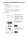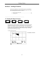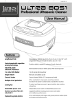
1
CRIT-LINE III User Manual ® 695 North 900 West, Kaysville, UT 84037 USA Toll Free 1-800-546-5463 · 801-451-9000 Fax 801-549-9250 www.crit-line.com CRIT-LINE III ® U.S. Federal law restricts this device to sale by or on the order of a physician. Frequency, duration, and parameters of treatment are to be determined by the prescribing physician. Fresenius Medical Care 695 North 900 West Kaysville, UT 84037 USA Fresenius Medical Care and triangle logo are trademarks of Fresenius Medical Care Holdings, Inc. or its affiliated companies. All other marks are the property of their respective owners. CRIT-LINE® III is a trademark of Fresenius Medical Care North America. This document is compatible with the CRIT-LINE® III monitor. Document No. 43-0002 Rev F (Last Update January 2013) Printed in the United States of America. Contents Contents Table of Contents ...............................................................i & ii Your Guide to the User Manual .........................................iii Section 1 The CRIT-LINE III System Introduction................................................................................ 1-1 Language Selection ................................................................... 1-2 The CLM III At A Glance ........................................................... 1-3 Fig.1 The CLM III Fig.2 Back Panel The Keypad ............................................................................... 1-4 Display Screens ........................................................................ 1-5 Primary Display Screens ................................................ 1-5 Secondary Display Screens ............................................ 1-6 Advanced Feature Pathways ..................................................... 1-7 Power Supply Adapter ............................................................... 1-8 Disposable Blood Chamber ....................................................... 1-10 Sensor Clip ................................................................................ 1-11 Internal Memory ........................................................................ 1-12 Optional Accessories ................................................................. 1-13 Symbols ..................................................................................... 1-14 Section 2 Set-Up Procedures Pre-priming Attachment of the Blood Chamber ......................... 2-1 Post-priming Attachment of the Blood Chamber ....................... 2-2 Sensor Clip Attachment ............................................................. 2-3 Section 3 Using the CRIT-LINE III Clearing the Memory ................................................................ 3-1 Running a Patient. ..................................................................... 3-3 Setting the Date and Time ......................................................... 3-6 Setting the Date. ............................................................. 3-6 Setting the Time .............................................................. 3-7 Entering the Patient ID, Station ID and Name ........................... 3-8 Entering the Patient ID .................................................... 3-8 Entering the Station ID .................................................... 3-9 Entering the Name .......................................................... 3-9 Entering the Patient/Station ID from Profile Screen ........ 3-10 Default Screen Selection ........................................................... 3-11 Screen Contrast Adjustment ...................................................... 3-13 i Contents Section 4 Ending a Session Ending the Dialysis Session ...................................................... 4-1 Output Options .......................................................................... 4-4 Printing ........................................................................... 4-4 Data Downloading .......................................................... 4-6 Selecting a Printer .......................................................... 4-6 Section 5 Advanced Features Hematocrit Limit – (Hct Limit) .................................................... 5-1 Hysteresis .................................................................................. 5-3 Recirculation .............................................................................. 5-3 Spot-checking ............................................................................ 5-6 Calibration Procedures .............................................................. 5-8 Verification Filter ............................................................. 5-8 Marking Clinical Interventions .................................................... 5-12 Section 6 Warning Messages Sensor Obstruction .................................................................... 6-2 No Blood Detected .................................................................... 6-2 Low Voltage ............................................................................... 6-2 Section 7 Performance Characteristics Operational Considerations ....................................................... 7-1 Percent Blood Volume Change....................................... 7-1 Corrections for Mean Cell Volume in Hct Sampling ........ 7-1 Reference Standard for Hematocrit ................................ 7-2 Reference Standard for Oxygen Saturation .................... 7-2 Hemoglobin Estimation ................................................... 7-2 General Precautions ....................................................... 7-2 Standard Specifications .................................................. 7-4 Section 8 Instrument Maintenance Cleaning the Sensor Clip ........................................................... 8-1 Cleaning the CLM III ................................................................. 8-2 Cleaning the Display Screen ..................................................... 8-2 Service ...................................................................................... 8-2 Warranty .................................................................................... 8-2 Preventative Maintenance ......................................................... 8-3 Electrical Safety Testing ............................................................ 8-3 ii Contents Your Guide to the User Manual This user manual has been designed to assist you in operating the CRITLINE III Monitor. It provides an overview and guide to the monitor’s use during hemodialysis. This manual includes a comprehensive table of contents, eight unique sections, and a collection of “Tech Notes” to answer questions and assist you in the clinical use of the CRIT-LINE. Each section covers a specific range of topics. Some topics may be addressed in greater detail in other sections and are clearly referenced throughout the manual. Individual sections instruct you on how to set up the monitor, use it during a dialysis session, and instrument maintenance. The advanced features topics enhance the CRIT-LINE’s usefulness and clinical effectiveness. iii The CRIT-LINE III System Section 1 The CRIT-LINE III System The CRIT-LINE® System includes the CRIT-LINE III Monitor (CLM III) with its sensor clip, the power supply adapter, and the disposable CRIT-LINE Blood Chamber (sold separately). The headings in this section are as follows: Introduction……………………………………………………………... 1.1 Language Selection……………………………………………………... 1.2 CLM III at a Glance………….................................................................. 1.3 The Keypad……………………….…………………………………….. 1.4 Display Screens…………………............................................................. 1.5 Advanced Feature Pathways……………………………………………. 1.6 Power Supply Adapter………………………………………………….. 1.7 Disposable Blood Chamber…………………………………………….. 1.8 Sensor Clip………………….................................................................... 1.9 Internal Memory……………................................................................... 1.10 Optional Accessories……………... ……………………………………. 1.11 Symbols…………………………............................................................. 1.12 _______________________ 1.1 Introduction Welcome to CLM III, a non-invasive, optical technology that helps ensure better clinical outcomes, patient safety, and staff confidence. The CLM III continuously monitors in real time the following blood parameters: hematocrit, percent change in intravascular blood volume, and oxygen saturation. Proper use of the CLM III can result in optimized fluid removal while preventing morbid events that result from blood volume depletion. This is accomplished via staff adjustment of ultrafiltration while monitoring graphically displayed changes in the patient’s circulating blood volume in real time during the treatment session. By continuously monitoring hematocrit and oxygen saturation, the CLM III provides diagnostic information concerning the vascular compartment during hemodialysis therapy. The CLM III is used in conjunction with the CRIT-LINE blood chamber, a sterile disposable viewing window that is inserted into the patient’s extra corporeal blood tubing. Blood parameters are displayed approximately one minute after measurement has begun and are displayed continuously thereafter throughout the dialysis treatment. 1-1 The CRIT-LINE III System _________________________________ 1.2 Language Selection The CLM III offers menu screens in several languages. English is the default language. To select a language, press the MENU and keys at the same time. When the language screen appears, scroll to the desired language and press SELECT Once the SELECT key has been pressed, the CLM III automatically returns to the MAIN MENU. All subsequent menus from this point forward will be in the selected language. The language can be changed at any time by following the process described above. 1-2 The CRIT-LINE III System ______________________________________ 1.3 The CLM III at a Glance Fig. 1 The CLM III Monitor Carrying Handle Power Switch DC Input Port Serial Data Port Parallel Data Port Sensor Clip Cable Fig. 2 The Back Panel 1-3 The CRIT-LINE III System _____________________ 1.4 The Keypad Operating the CLM III is done entirely through the keypad/menu-driven system. The keypad is used to choose the CLM III’s modes of operation. These modes are listed on display screens which show other modes of operation and their associated menu choices. The following instructions, coupled with the on-screen directions, comprise all that is needed to operate the CLM III. To enter main and optional menu screens, press the MENU key. MENU To move the cursor, use the UP ARROW or DOWN ARROW keys. To enter your selection, press the SELECT key. Warning Light SELECT Battery Charging Indicator The individual keys may have specific functions when working in a particular mode. These functions are clearly displayed on the display screen. The warning light flashes red when a warning message appears or when the Hct Limit has been exceeded. The small green light at the bottom of the keypad indicates the CLM III is connected to its power supply adapter and that the battery is charging. 1-4 The CRIT-LINE III System ____________________________ 1.5 Display Screens The CLM III utilizes three primary display screens, and several secondary screens that contain specific feature menus. To use the CLM III, simply follow the correct “path” to the function you desire. To assist you, each screen has a corresponding icon (seen to the right of the actual screen in this section). The “path” that you need to take to get to a specific function will be mapped at the beginning of each section detailing that function in this manual. Below each sections title are the icons of the screens that you will see on the way to your final display choice. Using the appropriate keypad choices, you can navigate through the screens in the mapped order. Primary Display Screens The MAIN MENU screen allows you to choose the operating mode of the CLM III. NOTE: New Monitors sold after January 2006 may not display the H ABF option on the Main Menu NOTE: New Monitors sold after August 2011 may not display the TQA option on the Main Menu The STARTUP screen is the central display for most CLM III functions. All measurements, warnings, or messages can be viewed from this screen. STARTUP The PROFILE screen displays a plotted graph of the change in the measured parameters versus time to allow you to see the trend in those measurements. PROFILE 1-5 The CRIT-LINE III System The secondary display screens provide you with specific function menus and data entry points. Secondary Display Screens The INITIAL DATA screen allows the input of various parameters. It appears after selection of PATIENT RUN, SPOT CHECK, and RECIRCULATION on the MAIN MENU. INITIAL The MEMORY FULL screen appears whenever the monitor is turned on and there is data in the memory, or if there is not enough space to save another patient run. MEMORY The STARTUP/SPLIT screen menu appears after pressing the MENU key while viewing the STARTUP screen. Its icon is the same as the STARTUP screen without the menu displayed. STARTUP 1-6 The CRIT-LINE III System ___________________________________________ 1.6 Advanced Feature Pathways From the MAIN MENU, various operational modes can be accessed. Selecting patient run directs you to the PROFILE screen after passing the INITIAL DATA screen, and the STARTUP screen. Each of the other modes (SPOT CHECK, RECIRCULATION, CALIBRATION, OUTPUT OPTIONS, and CONTRAST) has a specific menu screen associated with its functions. You can locate most of this information in Section 5-Advanced Features. Output Options is located in Section 4-Ending a Session and Contrast in Section 3-Using the CRIT-LINE III. Shown below are the specific icons associated with the individual menus. When there is more than one way to reach a specific mode, more than one “icon path” will be shown. SPOT RECIRC. CAL OUTPUT CONTR. 1-7 The CRIT-LINE III System ____________________________________ 1.7 Power Supply Adapter The power supply adapter supplied with the CLM III must be used as the connector to the AC power source. During normal monitoring, the power supply adapter should be plugged into a grounded AC wall outlet and connected to the CLM III via the power supply socket on the back panel (see Figure 2). (European and Japanese Power Supplies are not earth grounded.) The CLM III has dual classification. It is a class I device when operated on internal batteries and a class II device when connected to an AC outlet WARNING: Fresenius suggest that the brick portion of the power supply be mounted to the top of the Crit-Line Monitor or to the dialysis machine using Velcro, plastic ties, or other means in order to prevent the brick from “hanging” down from the power jack which can result in the power jack coming loose or even breaking. Mounting the brick portion of the power supply will also keep it off the floor and less likely to get wet. See warning message below. WARNING: TO PREVENT POWER SUPPLY FROM OVERHEATING OR FAILURE: KEEP POWER SUPPLY DRY 1. Do not place the power supply in or near an area that is or has the potential to become wet. 2. Do not use the power supply that shows signs of corrosive build-up 3. Do not use a power supply that shows signs of damage such as frayed cords. 4. Protect the power supply from dropping. 1-8 The CRIT-LINE III System The CLM III utilizes a green charging indicator light on the bottom of the keypad to indicate that the monitor is plugged into an AC wall outlet and that the battery is charging. If the green charging indicator light is not illuminated and a known good working power supply is plugged into the CLM III, the keypad will need to be replaced. Contact the spare parts department to order a replacement font panel (bezel assembly & kit). The voltage indicator located next to the lightning symbol at the bottom left corner of the MAIN MENU screen indicates the voltage of the power source (i.e. AC wall outlet or battery). This voltage must be above 10.3V for the monitor to operate. If the battery is fully charged, the CLM III will function for approximately 2 hours on battery power. During continuous clinical use, the CLM III should be attached at all times to a plugged in power supply adapter. Doing so will ensure that the battery is always fully charged. Remote spot-checking, data transfer, or a power failure may require battery use. The LOW VOLTAGE warning message (See Section 6) indicates a low battery state. This state may be corrected by connecting the CLM III to a power supply; otherwise, the CLM III will turn off after a twominute countdown. A discharged battery will fully charge in 36 hours when properly connected to its power supply adapter, regardless of whether or not the CLM III is in the ON or OFF position. If the CLM III Monitor has run to battery extinction, you must first turn the power switch OFF, and then reestablish power. Be sure the green indicator light is on and wait 20 seconds before turning the monitor ON. Once the CLM III is connected to its power supply adapter, full monitoring functions return, regardless of battery status. CRIT-LINE III BATTERY CHARGING CHARACTERISTICS 2.5 2.0 1.5 (HRS) OPERATING TIME Refer to the graph below for approximate operating time of the CLM III when operating on battery power. Charging time refers to the length of time the CLM III has been connected to its power supply adapter after it has automatically shut OFF. 1.0 0.5 0 0 35 5 10 15 CHARGING TIME REQUIRED (HRS) 20 1-9 25 30 The CRIT-LINE III System _______________________________________ 1.8 Disposable Blood Chamber The CRIT-LINE Blood Chamber is a sterile disposable cuvette designed to insure a consistent viewing area for the CLM III’s sensor in order to provide accurate, repeatable measurements. The blood chamber is attached to the arterial side of the dialyzer during the pre-dialysis set-up procedure. (See Section 2 for more information). WARNING: DO NOT USE THE BLOOD CHAMBER IF ITS PACKAGE HAS BEEN OPENED, EXPIRED, OR ITS STERILITY HAS OTHERWISE BEEN COMPROMISED PRIOR TO USE. THE PACKAGE HAS THE LOT NUMBER, MONTH AND YEAR IT WAS MADE, AND EXPIRATION DATE. The CLM III is highly sensitive to the optical properties of the CRIT-LINE Blood Chamber. Reprocessing of blood chambers may sterilize the blood chamber, but does not restore the optical properties of an unused, sterile blood chamber. Therefore, it is important that a new sterile blood chamber be used during each monitoring session. The viewing area of the disposable blood chamber should be kept clean and free of obstruction. Air bubbles trapped in the CRIT-LINE Blood Chamber may cause the instrument to underestimate the hematocrit measurement. A blood clot may also alter the hematocrit measurement. WARNING: PROPERLY DISPOSE OF THE BLOOD CHAMBER AFTER USE. . Disposable Blood Chamber 1-10 The CRIT-LINE III System _______________________ 1.9 Sensor Clip The CLM III’s sensor clip is comprised of an electronic light emitter/detector unit housed in a precision-molded clip. The sensor detects the absorption and scattering properties of light transmitted through the whole blood as it flows through the CRITLINE Blood Chamber. The sensor clip locks into place around the blood chamber. Incorrect placement will most likely result in incorrect measurements. (See Section 2 for more information). Sensor Clip Whenever the CLM III is not being used, the sensor clip should be placed on the verification filter on the side of the monitor. This provides protection from damage and keeps the sensor elements clean. (See section 8 for cleaning instructions). Never remove the clip from the verification filter by pulling on the sensor cable. 1-11 The CRIT-LINE III System _______________________________ 1.10 Internal Memory The CLM III records data via an internal, non-volatile memory. There is enough memory to store a total of 26 hours of dialysis sessions, or data from 170 spotchecking and/or recirculation tests. If there is data in the memory when the CLM III is first turned on, this data must be erased before proceeding. The option to print or download data prior to clearing memory is always available (See Section 3-Clearing the Memory). Prior to returning to the MAIN MENU screen from any monitoring activity, the CLM III determines if there is enough room in the memory to store at least five additional hours of data. If not, it will prompt you to clear the memory (See Section 3-Clearing the Memory). When the data is printed or downloaded, the entire contents of the memory are printed or downloaded. Data cannot be selectively erased. All files are deleted when clearing the memory. WARNING: ONCE ERASED, DATA CANNOT BE RECOVERED. BE SURE THAT PRINTING/DOWNLOADING ACTIVITIES ARE SUCCESSFUL PRIOR TO CLEARING THE MEMORY. HEADER 1 3 HR. PATIENT RUN FOOTER 1 Example memory configuration: The internal memory configures the data into a file as illustrated in the example on the left. The header contains the date and time, while the footer contains the patient and station ID information. HEADER 2 MAX. 26 HR. EQUIVALENT 1 HR. PATIENT RUN FOOTER 2 HEADER 3 SPOT CHECK DATA Each patient run begins with a header and ends with a footer. The entire data file, including all headers, footers, and data is downloaded or printed at the same time. Each file is printed on a separate output page. FOOTER 3 LAST HEADER LAST DATA LAST FOOTER ETC. 1-12 The CRIT-LINE III System _________________________________ 1.11 Optional Accessories Optional accessories are available to maximize the CLM III’s convenience and performance capability. These accessories include: I.V. Pole Mount– Part # CL90000023 The I.V. pole mount securely positions the CLM III to the I.V. pole of the dialysis machine. Using the pole mount frees the space on the top of the dialysis machine, and providing an excellent viewing angle of the CLM III’s screen. Wireless Printer Radio - Client – Part# CL10023029 Print wirelessly from the Crit-Line Monitor to any printer in your facility. The client radio attaches to the Crit-Line Monitor. This allows the treatment profile to be sent wirelessly to the server radio to have the treatment profile printed. Wireless Printer Radio - Server – Part# CL10023030 Print wirelessly from the Crit-Line Monitor to any printer in your facility. The server radio, which is connected to a computer, receives information from the client radio and sends this data to the printer software which then sends it to a printer. Crit-Line Printer Software – Part # CL10029504 This allows for the printout of treatment profiles at the end of each treatment. No patient data is stored when using this software. Crit-Line Reporter Software – Part # CL10029500 This software is used to record individual blood volume profiles. It is also capable of recording recirculation data, electronic storage of treatment date, as well as treatment profile printouts. Data Download Serial Cable – Part # CL90000012 This custom made DB9/RJ 45 cable is used for serial data downloading and serial printing. This cable is specially modified and cannot be store bought. Blood Chamber Tubing Adapter Set – Part# CL10021039 Individually packaged and pre-sterilized disposable blood chamber tubing adapter set for use with CRRT. Single use only, disposable, packaged 36 per box. For a complete listing of all products, visit our website at www.crit-line.com 1-13 The CRIT-LINE III System 1.12 Symbols The CLM III label, located on the base of each CLM III, has several descriptive symbols which are used to identify the CLM III’s critical characteristics. The following is an explanation for each of these internationally accepted symbols: Class II Equipment Type BF Equipment ! For use within temperature limits Read Instructions Before Use Manufacture Identification Certification European CRIT-LINE III Monitor Label 1-14 Set Up Procedures Section 2 Set Up Procedures This section details how to setup the CLM III for patient monitoring during dialysis. Section headings include: Pre-priming attachment of the blood chamber………………....................2.1 Post-priming attachment of the blood chamber ………………………….2.2 Sensor clip attachment ………………………………………...................2.3 _______________________________________________________________ 2.1 Pre-priming Attachment of the Blood Chamber Follow these basic steps to attach the disposable CRIT-LINE Blood Chamber to the dialyzer during the pre-dialysis setup. 1. Inspect the blood chamber and its sterile package prior to use. Do not use any blood chamber where the package has expired, been opened, or otherwise compromised. Refer to the blood chamber package label to ensure that the blood chamber expiration date has not expired. 2. Remove the blood chamber from its sterile package and remove the red cap. Attach it by inserting it perpendicular into the arterial fitting of the dialyzer. Twist the wings of the blood chamber until the lure-lock connector is secure in the dialyzer. 3. Remove the white cap from the blood chamber and attach it into the twist lock fitting of the arterial blood tubing set. 4. Ensure that all connections are tight and that there is no kinking at the arterial tubing set connection. 5. Prime the entire circuit with saline and remove air bubbles in the dialyzer using normal priming procedures, making sure that no air bubbles are trapped inside the blood chamber. NOTE: Any air bubbles present in the blood chamber will cause the hematocrit reading to be inaccurate, and the instrument may display the message: NO BLOOD DETECTED. NOTE: Improper attachment of the arterial line to the Disposable Blood Chamber can cause blood/saline to leak onto and into the Sensor Clip. The connection of the Disposable Blood Chamber to the arterial line must be leak-proof. This can only be done by holding the Disposable Blood Chamber (not the dialyzer) securely in one hand and attaching the arterial line with the other hand, twisting at the wings. Be careful that you do not cross-thread the connection, and then thoroughly check for leakage at both connection points before attaching the Sensor Clip. Ensure there is no kinking in the bloodlines. 2-1 Set Up Procedures _______________________________________________________________ 2.2 Post-priming Attachment of the Blood Chamber If the tubing set is already primed, a disposable CRIT-LINE Blood Chamber can be installed by following the same basic instruction found in Section 2.1 with the following changes. 1. Pre-prime the blood chamber using a 3ml syringe of sterile saline to remove air. 2. Stop the blood pump and the dialysate lines. 3. Apply hemostat clamps to both the arterial and venous tubing lines. 4. Disconnect the arterial tubing set from the dialyzer and attach the CRIT-LINE Blood Chamber to the arterial side of the dialyzer and bloodline in the manner described in Section 2.1. NOTE: Post-prime attachment of the blood chamber may introduce air into the dialyzer and blood chamber. It is therefore important to remove the air in the blood chamber by inverting the dialyzer and tapping it until all air bubbles have migrated past the blood chamber to the air trap. 5. Remove the hemostat clamps and restart the blood pump. 6. Ensure the outside of the blood chamber is dry before attaching the sensor clip. NOTE: Improper attachment of the arterial line to the Disposable Blood Chamber can cause blood/saline to leak onto and into the Sensor Clip. The connection of the Disposable Blood Chamber to the arterial line must be leak-proof. This can only be done by holding the Disposable Blood Chamber (not the dialyzer) securely in one hand and attaching the arterial line with the other hand, twisting at the wings. Be careful that you do not cross-thread the connection, and then thoroughly check for leakage at both connection points before attaching the Sensor Clip. Ensure there is no kinking in the bloodlines. 2-2 Set Up Procedures ______________________________________ 2.3 Sensor Clip Attachment When properly attached, the sensor clip will lock into place on the blood chamber. It can be attached in either direction on the blood chamber. Ensure that it is secure prior to proceeding. NOTE: The sensor clip must be attached before monitoring takes place (i.e. before pressing START RUN). Care must be taken to ensure that the sensor clip is properly in place before attempting monitoring in order to ensure accuracy of the initial hematocrit reading. The CLM III’s sensor clip is continuously scanning for blood. In order for the sensor to determine a true starting hematocrit value, which initiates the processing of data, blood must be flowing throughout the dialyzer circuit and the blood pump must be running. These conditions must be met prior to selecting START RUN. If START RUN is selected prior to placing the sensor clip on the blood chamber, or if the blood circulating within the dialyzer is still mixing with saline, the initial hematocrit will be diluted and the hematocrit value will be lower than the “true” circulating hematocrit. Starting while the sensor clip is still on the verification filter will reflect the hematocrit and oxygen control values as the starting values. The initial hematocrit value is the starting point from which all blood volume calculations are made. Therefore, it is essential that the first hematocrit value measured by the CLM III be indicative of the circulating blood. To ensure an accurate initial Hct reading, visually verify proper blood flow in the dialyzer circuit prior to pressing START RUN. (See Section 4-Ending the Run, for information on when to remove the Sensor Clip). 2-3 Using the CRIT-LINE III Section 3 Using the CRIT-LINE III Blood volume monitoring is the primary function of the CLM III. This section explains how to get from the initial screen (i.e. the screen that appears when the CLM III is turned on), to the blood volume profile, oxygen saturation and hematocrit screens. The headings in this section include the following: Clearing the Memory………………….……....………………. 3.1 Running a Patient…………………………................................ 3.2 Setting the Date and Time………….…………………………. 3.3 Entering the Patient and Station ID…………………………… 3.4 Default Screen Selection……………….………………………3.5 Screen Contrast Adjustment…………………........................... 3.6 ______________________________ 3.1 Clearing the Memory MEMORY The CLM III’s memory is designed to record up to 26 hours of continuous data. Internal memory is non-volatile. Therefore, in the event that the monitor is turned OFF, the memory will be maintained until it is erased. Anytime patient monitoring has taken place and the power is cycled from OFF to ON, MEMORY FULL will be displayed. Once this message is displayed, memory must be cleared before the CLM III will allow any monitoring activity. NOTE: Printing or downloading data will not clear the memory. Once one or both of these options have been completed, the data must be cleared by selecting MEMORY CLEAR on the MEMORY FULL screen. MEMORY FULL will appear whenever: The CLM III is turned on and there is data in memory. There is not enough memory to monitor a new five-hour treatment. There is data in the memory prior to performing an accuracy verification test. 3-1 Using the CRIT-LINE III The MEMORY FULL screen provides two options: Data output via printing or downloading data (see Section 4–Output Options) Clearing the Memory To proceed beyond this screen, the memory must be cleared by: Position the cursor next to MEMORY CLEAR with the arrow key, press SELECT. Y denotes Yes N denotes No Press MENU to clear the memory. Press SELECT to save the memory for future printing/downloading NOTE: Once the memory has been cleared, data cannot be retrieved. If you do not want to clear the data (i.e. you want to print or download data prior to erasing) the output options feature must be selected (see Section 4 – Output Options). 3-2 Using the CRIT-LINE III ________________________________ 3.2 Running a Patient MEMORY MAIN INITIAL SETUP PROFILE Once the memory has been cleared, the MAIN MENU screen will appear. By default, the cursor will be next to PATIENT RUN. Pressing Select will activate the Initial Data screen. Software Version Monitor Serial Number Battery Voltage The next screen, the INITIAL DATA screen, has a prompt for data inputs in the reverse video in the lower left of the screen providing the options shown below. You may ignore the PATIENT ID prompt and proceed by simply pressing the SELECT key. (These fields can also be entered during the run if desired.) Select START RUN to ignore input fields and begin patient monitoring. NOTE: Entering the patient and station ID, as well as setting the date and time, will be discussed in detail in a later section. 3-3 Using the CRIT-LINE III The START UP screen will appear as shown below until a valid starting hematocrit value has been determined. The initialization process takes approximately one minute. START UP Screen Blood parameter monitoring begins as soon as numeric data appears on the screen. The highlighted window will instruct you to either set a Hct Limit or to wait ten seconds for the PROFILE screen to appear. You can choose to set a Hct Limit at this time, or access this screen later to set a limit. The Hct Limit is adjusted or set by pressing or (see Section 5 – Hematocrit Limit). If there is no keypad input, the screen will proceed to the default profile screen after 10 seconds (see example above). NOTE: You can never set a hematocrit limit that is lower than the starting or current hematocrit. 3-4 Using the CRIT-LINE III Once a PROFILE SCREEN appears, it can be exited at any time by press either MENU or SELECT . Pressing either of these keys will cause the START UP screen to appear. Anytime the START UP screen is accessed, the monitor will again automatically revert to the PROFILE screen in 10 seconds if no other keypad input takes place. Blood parameters are monitored continuously throughout the entire dialysis session. In the lower portion of the PROFILE screen, there are five information windows that indicate length of time the patient has been monitored (TIME), the current instantaneous Hct (HCT), instantaneous estimated HgB (Hemoglobin), percent change in blood volume (%BV), and the oxygen saturation (SAT). The displayed HgB value is calculated from the measured Hct. The oxygen saturation (SAT) is reflective of an arterial saturation if the blood monitored is from a fistula or graft, or a venous saturation if blood is coming from a central venous line. (See Section 7 for further information). NOTE: If any of the four information windows appear in reverse video, this means that the CLM III is momentarily revalidating data. Previously recorded values will continue to display until new stable values are measured and the reverse video clears. The BV PROFILE screen is the “default” profile screen of CLM III. The main function of the BV PROFILE screen is to show the continuous percentage change in a patient’s circulating intravascular blood volume over the course of a dialysis session. Using the hematocrit data, the CLM III calculates and graphically displays the percent change in blood volume. Where: %BV = ((H0/H)-1)X100 H0=Hct(start) H =Current Hct 3-5 Using the CRIT-LINE III ___________________________________________ 3.3 Setting the Date and Time MAIN INITIAL The CLM III is equipped with an internal clock and calendar that are powered by a real time clock battery. This battery is different than the battery that powers the CLM III when it is not powered by a power supply. When the power is off the settings are maintained. The clock and calendar have been installed so that data, whether printed or downloaded, will be time and date coded. The INITIAL DATA screen is the only screen where the date and time may be set. Date and time can only be adjusted in-between patient runs. NOTE: The internal clock runs on a 24-hour clock standard. Setting the Date To set the date: Scroll the cursor next to DATE ADJUST and press Select. The DATE MENU screen will appear and provide the options shown below: Scroll the cursor next to MONTH and press Select. 3-6 Using the CRIT-LINE III The month data entry window will appear. To set the month: Scroll the cursor next to the current month. Press Select. To set the day, scroll the cursor next to DAY in the DATE MENU and press SELECT. The numeric data entry window will then appear. Scroll the cursor next to the number of the first digit in the current day. Press Select Do the same for the second digit in the day and press SELECT. The DATE MENU window will then become active again allowing you to set the YEAR using the same procedure. NOTE: If you inadvertently choose a wrong digit when correcting the day and year, scroll to DEL (delete) and push SELECT to erase the entry. If the day or year is a single digit number you must select zero as the first digit and then select the digit that signifies the day or year. Once you have finished setting the date, scroll to RETURN on the DATA MENU and press SELECT. This will return you to the INITIAL DATA screen. If you make a mistake, simply repeat the above process. Setting the Time Choose TIME ADJUST from the INITIAL DATA screen. Using the same procedure used to set the date, set the hours (24-hour clock) and minutes of the internal clock Once the time has been set, scroll to RETURN and press Select. This will return you to the INITIAL DATA screen. NOTE: If you inadvertently choose the wrong first digit, scroll to DEL (delete) and press SELECT to erase the entry. If the hour or minute is a single digit number you can enter the single digit and then select SAVE to enter that digit. Or you can select zero as the first digit and then select the digit that signifies the hour or minute. NOTE: Once you have initiated blood volume monitoring you cannot reset the date and time without cycling the power, clearing the memory and accessing the INITIAL DATA screen. But, you can also change the date and time between patient runs. 3-7 Using the CRIT-LINE III ________________________________________________ 3.4 Entering the Patient ID, Station ID and Name MAIN INITIAL The CLM III provides the additional option of entering a patient and station ID. This information will appear at the top of printed graphs as well as any downloaded data. This option will enable you to keep better track of patient records. If this information is not entered during the initial setup, the patient and station ID can be entered at any time during the dialysis session or at the end of the treatment session. Entering the Patient ID: You can enter the PATIENT ID from either the INITIAL DATA screen prior to starting a run, or the SETUP screen during a run. To enter the PATIENT ID from the INITIAL DATA screen: Scroll to PATIENT ID and press SELECT. The alpha numeric data entry window will appear. Enter up to four characters, any combination of letters, numbers, and spaces to identify the current patient. To enter the PATIENT ID: Scroll to the first character and press SELECT. 3-8 Using the CRIT-LINE III Do the same for each character. If you wish to enter a space, scroll to that option instead of a letter. Once you have entered the third letter or space, pressing SELECT will take you back to the INITIAL DATA screen. If you choose less than four characters, pressing SAVE will take you back to the INITIAL DATA screen. NOTE: If the patient’s ID is only one letter, select the letter and then select SPACE twice. If you inadvertently select the wrong first initial select DEL (delete) to erase the entry. You can change the Patient ID, Station ID, or NAME any time during the dialysis session. If you plan on storing more than one dialysis session, recirculation test or spot check, be sure to always enter the patient ID so the printout can be referenced back to the individual patient for which data has been gathered. Patient data is erased from the monitor when the current dialysis session is stopped. Entering the Station ID: Once you are back into the INITIAL DATA screen, scroll to STATION ID and press SELECT: This will open and activate the numeric data entry window. Scroll to the first digit of the Station ID and press SELECT. Next, scroll to the second digit of the STATION ID and press SELECT. This will save your entry and return you to the INITIAL DATA screen NOTE: If the station ID is only one digit, select zero as the first digit. DEL (delete) will also allow you to erase a previous entry. Entering the Name The CLM III also provides the option to enter up to 12 digits for name or ID number. The ability to enter this data has been included so that printed and downloaded data can be easily identified, and it will only appear on the printed data sheet and the downloaded data. The option is only available in the English software. To enter a name or ID number, scroll to NAME and press SELECT. Scroll to NAME and press SELECT. 3-9 Using the CRIT-LINE III This will activate the alpha numeric data entry window. Scroll to each letter or number you wish to enter and press SELECT. Once the entry is complete scroll to SAVE and press SELECT to return to the INITIAL DATA screen prior to starting the run or the Setup Screen during the run. Save the data and continue on to patient monitoring. Entering the Patient ID and Station ID from the Profile screen: PROFILE START UP SETUP You can enter the PATIENT and STATION ID and NAME after you have started blood volume monitoring and a PROFILE screen has been activated. To exit the PROFILE screen and enter the START UP screen press SELECT or MENU. Once in the START UP screen press MENU. The START UP menu will then appear. The cursor will be next to SETUP/ STOP. Press SELECT. 3-10 Using the CRIT-LINE III The SETUP MENU will be accessed and provide the option to enter the PATIENT and STATION ID and NAME. From this point, follow the instructions in the previous section for entering the PATIENT and STATION ID and NAME. To get back to the PROFILE screen, scroll to CONTINUE in the SETUP MENU and press SELECT. This will return you to the START UP screen, which will then automatically revert to the PROFILE screen after 10 seconds. _______________________________________ 3.5 Default Screen Selection PROFILE START UP The preset default display screen is the %BV (blood volume) screen. 3-11 Using the CRIT-LINE III If you wish to see the profile for hematocrit or oxygen saturation (as shown above), you can change the default screen selection. To change the profile display, access the START UP MENU window. If you are in the PROFILE screen, this is done by first accessing the START UP screen by pressing either MENU or SELECT and then pressing MENU. Once in the START UP MENU window, scroll down to the choices under DEFAULT SCREEN. Choose the parameter you wish to monitor and press SELECT. Changing the default screen from BV to either of the other two options will only change the default for that specific dialysis session. Cycling the power or starting a new patient run will always reset the default screen to the blood volume profile. NOTE: In the upper right hand corner of the START UP screen a “BV ”, “SAT”, or “HCT” indicates the current default screen. 3-12 Using the CRIT-LINE III _______________________________________ 3.6 Screen Contrast Adjustment MAIN CONTRAST To adjust the screen contrast, select the CONTRAST option from the MAIN MENU. Scroll the cursor next to CONTRAST, and press Select. From the Contrast Adjust Screen use the UP and DOWN arrow buttons to lighten or darken the screen contrast. Each press of will lighten the screen, and each press of will darken the screen. Once the contrast has been adjusted, press the MENU button to save the adjustment setting. To return to the MAIN MENU without saving contrast adjustments made, press the SELECT button. Contrast can only be changed in between patient runs. Older model CLM III’s may not have the option to adjust the screen contrast in the Main Menu. If you have an older CLM III that requires the screen contrast to be adjusted, contact the spare parts department to order a screen adjustment kit. 3-13 Ending a Session Section 4 Ending A Session This section explains how to end a monitoring session. Also included in this section are instructions on how to use the output options on the CLM III. The headings in this section are as follows: Ending the Dialysis Session………………………………….. 4.1 Output Options……………………………………………….. 4.2 ____________________________________________ 4.1 Ending the Dialysis Session PROFILE STARTUP SETUP OUTPUT Monitoring with the CLM III should be concluded prior to the rinse-back procedure, stopping the blood pump, or moving the sensor clip back to the verification filter. Otherwise, the CLM III may indicate a false Hct reading. If the CLM III does read a false Hct, it will cause the blood volume and Hct graphs to rescale. Rescaling makes the information on the graph difficult to interpret. Properly ending a monitoring session will prevent unnecessary rescaling. To end a monitoring session: Press MENU or SELECT 4-1 Ending a Session This switches the display to the START-UP screen. Press MENU to access the START-UP menu. The START-UP Menu will be displayed. Position the cursor next to SETUP/STOP Press SELECT If you desire, you may input Patient ID, Station ID, or Name at this time. To stop, position the cursor next to STOP and press SELECT 4-2 Ending a Session This ends monitoring of the current run and stops the collection of data. The Patient ID and Name will be erased but the Station ID, Time, and Date remain in the memory. NOTE: The sensor clip should be removed from the blood chamber and secured on the verification filter at this time. The MAIN MENU will now be displayed. Select Patient Run to begin another monitoring session. See Section 4-Output Options. NOTE: If the CLM III calculates that there is not enough memory to record five additional hours of dialysis data, the MEMORY FULL screen will appear prompting you to download and/or clear the memory before attempting to initialize another patient run. Reference the appropriate heading in Spot Check, Recirculation, and Calibration for specific information on the other menu choices provided on the MAIN MENU screen (see Section 5-Advanced Features). 4-3 Ending a Session ___________________________ 4.2 Output Options MAIN OUTPUT MEMORY OUTPUT NOTE: See the Tech Notes Section on Printing Graphs and Data Retrieval for additional information on this subject. The OUTPUT OPTIONS menu can be reached from either the MAIN MENU screen or the MEMORY FULL screen. Printing Choose the printing method desired to print all Patient Runs in memory. 4-4 Ending a Session Information can be transferred by using either the parallel or serial port located on the back panel. (See Section 1-The CRITLINE At A Glance, Fig. 2). The port you select will depend on whether or not the printer you are using has a parallel or serial data port (most new printers have both). For more information refer to the Tech Notes Section on Printing Graphs and Data Retrieval. Printed data for each PATIENT RUN consists of three graphs on a single page of 8.5 by 11.5 inch paper. These graphs include a profile of the hematocrit, percent blood volume change, and oxygen saturation. Also included is the information as shown on the following sample printout. HEMA METRICS Patient ID. = **** Hct (start) = 30.2 Hct (max) = 36.5 Hct Limit = 38 Sat (min) = 88.2 Recirculation % 13 CRIT LINE Instrument S/N 174-300001 Name: Station ID. = ** Date 05/04/1998 Start Time 09:00:04 Stop Time 12:15:32 Calibration Date 03/03/1998 Last Verification Date 05/03/1998 38 36 HCT 34 32 30 0 1 2 3 4 0 1 2 3 4 0 1 2 3 4 5 0 %BV -10 -20 100 95 SAT 90 85 80 If RECIRCULATION or SPOT CHECK tests have been conducted from the MAIN MENU, the results will be printed on one separate page for each patient tested. NOTE: Printing data does not clear the memory. Once printing has taken place, the data can be erased by selecting MEMORY CLEAR then MENU to Clear Memory. After printing successfully, select MEMORY CLEAR then Menu to Clear Memory to move back to the MAIN MENU. Once you have printed you cannot return to the MAIN MENU until you have cleared the memory. 4-5 Ending a Session Data Downloading NOTE: See the Tech Notes Section on Printing Graphs and Data Retrieval for additional information on this subject. This option allows data to be downloaded from the CRIT-LINE III as text files at the conclusion of a monitoring session. Data can also be retrieved continuously during the monitoring session by proper connection of the serial port to a computer. Information is transferred from the serial data port located on the back I/O panel (see Section 1-The CRIT-LINE III at A Glance for specific location). After downloading data, you have the options of clearing the memory or selecting RETURN to enter the MAIN MENU. Unlike printing, you do not have to clear the memory to return to the MAIN MENU after downloading. NOTE: Downloading data does not erase the files from the memory. Data files are only erased when the memory has been manually cleared (see Section 3 - Clearing the Memory). Selecting a Printer The Crit-Line has several print drivers from which to choose. If using a HewlettPackard (HP) or HP compatible printer the HP LaserJet driver should be selected. The Printy A and B drivers are to be used when printing to the Printy family of printers. The default print driver is the HP LaserJet. Also available is the pc printer option which is used with the printer software to generate a printout from a computer. This option is the preferred option when a compatible printer is not available. To select a driver, scroll the cursor to SELECT PRINTER (found in the OUTPUT MENU) and press SELECT. To select a print driver: Scroll to the desired printer and press SELECT. The driver selected will then have the double asterisks to its left. To return to the MAIN MENU select RETURN. 4-6 Advanced Features Section 5 Advanced Features The CLM III provides several advanced features. Although these advanced features are not necessary for day-to-day operation of the CLM III, using them will allow you to maximize the effectiveness of the monitoring process. These advanced features include: Hematocrit Limit…………………………………………… 5.1 Hysteresis……………………………………………........... 5.2 Recirculation………………………………………….......... 5.3 Spot-checking……………………………………………… 5.4 Calibration…………………………………………………. 5.5 Marking Clinical Interventions and Events….…….………. 5.6 ___________________________________________ 5.1 Hematocrit Limit - (Hct Limit) PROFILE START UP NOTE: See the Tech Notes Section on Hypovolemia for additional information on this subject. The Hct Limit feature provides a way for the clinician to be alerted via an audible and visual alarm when the patient’s hematocrit has reached a pre-selected hematocrit limit level. Prior to setting a hematocrit limit, the user should fully understand this subject (see the Tech Notes Section on Hypovolemia). A hematocrit limit can be set and/or changed at any time during the monitoring process. When viewing the START-UP screen prior to the automatic change to the PROFILE screen, the HCT LIMIT block will blink and display asterisks instead of numbers. The Hct Limit that is typically set for any given patient is one or two Hct units below the hematocrit at which that patient experiences morbidity (i.e. nausea, vomiting, lightheadedness, etc), thereby providing a comfortable “margin of safety” for the patient run. The Hct Limit can be set by pressing the up or down arrow keys. The Hct Limit can never be set below the starting Hct or the current Hct level, whichever is higher. 5-1 Advanced Features Each press of will raise the Hct limit one unit, and each press of will lower the Hct limit one unit. To set the Hct Limit during a monitoring session, press the MENU key to return back to the START-UP screen. The value can be entered as explained above, using the arrow key(s). Upon returning to the BV profile monitoring screen, the Hct limit will be converted to appropriate units and displayed as a dashed, horizontal line on the graph. In the BV profile mode, the Hct Limit is converted into %BV units and appears as the “CRIT-LINE” shown above. This line will appear in both the BV and the Hct profile screens. No Hct Limit information is displayed when viewing an oxygen saturation profile screen. When the patient’s hematocrit rises to the level of the hematocrit limit, an audible warning will sound and the red light located between the arrow keys will flash. To silence the alarm, press any key. Press the Up Arrow key or Down Arrow key to raise or lower the value of the hematocrit limit as indicated after patient assessment. MENU SELECT 5-2 Advanced Features __________________ 5.2 Hysteresis The CLM III has a hysteresis (alarm delay) feature. This feature prevents the alarm from turning off until the patient’s Hct is 0.25 Hct units lower than the established Hct Limit. This feature has been added to prevent the alarm from sounding ON and OFF as the patient’s Hct toggles at the Hct Limit. To change the default value of 0.25 to another value, press the MENU and DOWN ARROW keys at the same time. Scroll to the desired value and press the select button. To save this value, scroll to “SAVE” and press Select. Otherwise, the previously selected default value (the value which appears next to the word “SAVE”) will be the default value once the CLM III power has been recycled. __________________ 5.3 Recirculation MAIN INITIAL STARTUP PROFILE START UP RECIRC. RECIRC. NOTE: See the Tech Notes Section on CRIT LINE III Access Recirculation for additional information on this subject. 5-3 Advanced Features The CLM III has an access recirculation feature that estimates the amount of blood that is being recirculated back into the dialysis circuit instead of the patients circulating volume. This feature provides a good indication of the effectiveness of the patient’s access (i.e. fistula, graft or catheter). To utilize this feature, proceed to the MAIN MENU. Scroll the cursor next to RECIRCULATION, and press Select. This feature is also available during a patient run. To momentarily leave profile monitoring and conduct a recirculation test, press MENU or SELECT to move to the START-UP screen. Then press MENU to bring up the START-UP menu. Scroll the cursor next to RECIRCULATION, and press Select NOTE: When performing a recirculation test during patient monitoring, the CLM III will continue to monitor blood parameters. No data will be lost or significantly altered while performing recirculation tests. If you began the path to RECIRCULATION directly from the MAIN MENU, an INITIAL DATA screen will appear allowing you to enter necessary patient and station data. You will then proceed through the STARTUP screen to RECIRCULATION. The CLM III displays a list of instructions on how to perform a recirculation test. This list is abbreviated from the comprehensive instructions available in the Tech Notes Section on Crit-Line III Access Recirculation. 5-4 Advanced Features The CLM III estimates recirculation by measuring the effect on hematocrit that a bolus of saline has when injected into the venous and arterial lines. NOTE: See the Tech Notes Section on Access Recirculation for additional information on this subject. Follow the on-screen directions and press the MENU key. At the conclusion of the test, the recirculation percentage will be displayed on the screen. It is now possible to REPEAT the test or continue monitoring by selecting CANCEL. This calculated value is also present on printed charts and downloaded data (see Section 4-Output Options). If more than one recirculation test is performed during a PATIENT RUN only the most recent value will be displayed and printed. If RECIRCULATION is accessed from the MAIN MENU, the SAVE option will appear at the end of the RECIRCULATION measurement. SAVE allows the user to record selected recirculation test results in memory and also to add the patient ID if not already done. Tests that are saved will appear on a separate page when the printed. Hitting save goes back to recirculation, but that test is saved. Hitting return goes to recirculation for the next test. 5-5 Advanced Features _________________________ 5.4 Spot-checking MAIN INITIAL STARTUP SPOT The CLM III can also be utilized to quickly measure the hematocrit and oxygen saturation values of multiple patients. To perform spot check measurements, perform the following steps : From the MAIN MENU scroll to SPOT CHECK. Press Select The INITIAL DATA screen will appear so you can input the PATIENT and STATION ID. Scroll the cursor next to START RUN and press Select The START-UP screen will appear and denote SPOT CHECK in the warning or message block. The notation SC will appear in the upper right corner of the display screen to indicate that you are in the Spot Check mode. 5-6 Advanced Features NOTE: A Hct Limit cannot be set during spot checking, nor will the monitor revert to a profile monitoring screen. Once a Hct and Sat value has been determined, another Hct and O2 Sat sample may be taken by attaching the CLM III sensor clip onto the next patient’s CRIT-LINE Blood Chamber. Once attached, the SPOT CHECK message on the screen will flash indicating that data is being processed. When complete the asterisks in the Hct and Sat boxes will be replaced with number values. Pressing the MENU key will switch the screen to the SETUP MENU. SAVE completes the data file. PATIENT and STATION ID and NAME can be changed as needed. CONTINUE to Spot Check the next patient. STOP returns you to the MAIN MENU. Whenever SAVE is selected, the current PATIENT ID and STATION ID are recorded into memory along with their corresponding Hct and O 2 Sat readings. If you do not plan to print or download the spot check data it is not necessary to save the files in order to monitor another patient. NOTE: If you choose SAVE, be sure to change the PATIENT ID and STATION ID numbers as you move from patient to patient so that the processed data is saved under the correct identification. Selecting SAVE erases the current PATIENT ID. The STATION ID is saved for subsequent runs. The information contained in the saved data files can be printed or downloaded if desired (see Section 4-Output Options for more information). Selecting STOP completes the spot checking session. Data can be downloaded if desired at this time, but must be cleared from memory to proceed with any additional patient monitoring. 5-7 Advanced Features _____________________________________ 5.5 Calibration Procedures MAIN CAL The CLM III is calibrated by the manufacturer and should require no further calibration. However, the instrument is equipped with a verification filter to access and insure accuracy. Also a self-calibration routine can be performed if indicated by the verification routine. The monitor is required to be verified for accuracy at least once per month. The last date when the verify accuracy test was performed will appear on every treatment printout. The CLM III monitor is designed to detect component and memory failures that could potentially result in the display of erroneous information. If an error or component failure is detected, the system will display an error message and stop recording parameter values (see Section 6-Warning Messages). Verification Filter The verification filter is a specially modified blood chamber attached to the side of the monitor. It is included with each instrument and can be used to verify that the instrument is operating within normal parameters (see Section 1-The CRIT-LINE III At A Glance). For verification, attach the CLM III sensor clip to its verification filter so that it locks firmly into place. NOTE: Each verification filter is instrument specific and should not be used to calibrate any instrument except the one to which it is attached . From the MAIN MENU, scroll the cursor next to CALIBRATION and press SELECT 5-8 Advanced Features From the CALIBRATION MENU Scroll the cursor next To VERIFY ACCURACY and press Select. The message block on the display screen will read “VERIFYING ACCURACY”. In sixty seconds, one of two possible messages will be displayed. Verification Passed or Verification Failed. 5-9 Advanced Features The screen will read “VERIFICATION PASSED READY FOR CLINICAL USE SELECT RETURN” indicating that the instrument is ready for clinical use. Select RETURN to go to the MAIN MENU. If the CLM III is unable to verify accuracy, it will prompt you to retry the VERIFY ACCURACY routine again after ensuring that the sensor clip is properly attached to the verification filter and the verification filter is clean. > VERIFY ACCURACY If the VERIFY CALIBRATION ACCURACY routine fails the second time, the monitor will return RE-CALIBRATE to the original CALIBRATION MENU. Check to make sure that the sensor clip is MENU RETURN properly attached to the verification filter. SELECT OPTION by moving cursor ATTACH SENSOR TO VERIFICATION FILTER !! VERIFYING ACCURACY PLEASE WAIT 02:00 5-10 Advanced Features Select RE-CALIBRATE. During this 4-minute routine, the monitor internally corrects deviations from calibration coefficients set at the factory. VERIFICATION FAILED SELECT RE-CALIBRATE The monitor may determine that the sensor is the cause of the malfunction. Retry VERIFY ACCURACY after properly attaching the sensor clip to the verification filter. If this message continues, it is necessary to contact your service representative. SENSOR MALFUNCTION RETRY OR REFER TO THE USER MANUAL Upon successful completion of RE-CALIBRATE, the monitor will indicate that it is ready for clinical use. It is not necessary to VERIFY ACCURACY if RE-CALIBRATE is successful. CALIBRATION DONE READY FOR CLINICAL USE SELECT RETURN If RE-CALIBRATE fails, the instrument is unable to recalibrate itself to the necessary parameters. If this should occur, make sure the verification filter is clean and that the sensor clip has been properly attached (Refer to Section 2). RE-CALIBRATE may be retried until successful. If VERIFY ACCURACY and RE-CALIBRATE should both fail, the CRIT-LINE will prevent you from exiting the CALIBRATION MENU and will only allow you to select RECALIBRATE. This safety feature prevents patient monitoring if the monitor is not providing data representative of actual values. RE-CALIBRATION HAS FAILED RETRY OR REFER TO THE USER MANUEL INVALID SELECTION SYSTEM IS NOT READY FOR CLINICAL USE!! If the CLM III should fail both the VERIFY ACCURACY and RE-CALIBRATE routines, either the Sensor clip is improperly attached to the verification filter or the CLM III’s self-diagnostic capabilities have determined that a problem exists. If you are certain the sensor clip is properly attached to the verification filter and RE-CALIBRATE continues to fail, contact your service representative. NOTE: If you wish to verify accuracy after data has been collected (i.e. after a patient run instead of prior to a patient run), the MEMORY FULL screen will appear. You must erase all data prior to performing a verify accuracy test. Any data you want to retain must be printed or downloaded prior to performing the verify accuracy test. 5-11 Advanced Features _____________________________________________________________ 5.6 Marking Clinical Interventions and Events PROFILE The CLM III provides the capability of inserting clinical intervention/event markers into the profile screens. Pressing either the UP or DOWN ARROW keys activates event markers. This encodes a marker in the data file, and positions a visible arrow on the display screen at the point during the dialysis session when the key was pressed. (These markers appear on each profile screen and the printed graphs). Press either or to insert an Event Marker. This feature is useful for marking the time of various clinical interventions and events (saline bolus administration, Trendelenburg, etc.) and/or physiological changes (food intake, etc.) that occur during the treatment. Event markers can be inserted after five minutes or monitoring and as frequently as every five minutes for the duration of the session. For retrieving data after a monitoring session, see the Tech Notes Section on Printing Graphs and Data Retrieval. 5-12 Warning Messages Section 6 Warning Messages This section details the warning messages that may appear in the WARNING or MESSAGE BLOCK on the screen of the CLM III. It also describes the appropriate action necessary for correcting the cause of the message. The WARNING or MESSAGE BLOCK is found in the lower right corner of the display in reverse video. If you are currently viewing a profile screen, the display of a warning or message will automatically changes the display to the START-UP screen, as illustrated below. WA R N IN G or ME S S AG E BL O C K Warning messages that can be displayed in the Warning or Message Block include: Sensor Obstruction………………………………………………….. 6.1 No Blood Detected……………………………….………………….. 6.2 Low Voltage…………………………………………………………... 6.3 6-1 Warning Messages _________________________________ 6.1 Sensor Obstruction This message appears when the sensor is obstructed or the blood becomes so dense (e.g. a blood clot) that it absorbs too much light for a hematocrit measurement in the normal blood parameter range. ERROR SENSOR OBSTRUCTION If the patient’s hematocrit is below 60 and this warning message appears, the sensor is probably obstructed with a foreign material that has come between the sensor clip and the blood chamber. To correct this problem, remove any foreign materials that could be causing an obstruction (see Section 8-Cleaning the Sensor Clip). ________________________________ 6.2 No Blood Detected ERROR This message indicates that an insufficient number of red NO BLOOD blood cells are present in the medium being viewed by the DETECTED sensor (e.g., monitoring the saline prime, monitoring when air bubbles are present in the blood chamber, during a saline flush etc.) or that the sensor is detached from the CRIT-LINE Blood Chamber. To correct this condition, make sure that the sensor is firmly locked onto the blood chamber, and that blood (not saline) is flowing through the blood chamber. _______________________ 6.3 Low Voltage When the Low Voltage message appears, you have two minutes before the CLM III will automatically shut itself OFF. To prevent this from happening, immediately attach the CLM III to a power supply adapter that is plugged into a power outlet. WARNING LOW VOLTAGE SHUTDOWN IN 02:00 If the CLM III is running without its power supply adapter, the internal battery powers the unit. A fully charged battery will operate the CLM III for approximately two hours before it needs to be recharged (see Section 1-Power Supply). If the CLM III automatically shuts off after the two minute countdown, it will not restart with the simple connection of the external power. The power switch must be turned off for approximately 20 seconds before attempting to turn the unit on again. This resets the internal electronic battery protection circuitry. If the unit is turned on with insufficient power at this point, the unit will auto shutdown in two seconds to protect the battery. 6-2 Performance Characteristics Section 7 Performance Characteristics The headings in this section are as follows: Operational Considerations……………………………………………….. 7.1 Standard Specifications…………………………………………………… 7.2 ___________________________________________ 7.1 Operational Considerations Each component of whole blood (erythrocytes, plasma, etc.) absorbs light differently. The CLM III trans-illuminates the blood with multiple wavelengths of light allowing the various components to be identified and measured optically. The level of oxygen saturation can also be measured by detecting the different absorption characteristics of hemoglobin in its oxygenated and deoxygenated forms. However, to determine the hematocrit value, the absorption and scattering characteristics of the entire red blood cell must be considered as well as the absorption qualities of hemoglobin (see Tech Note - CRIT-LINE Hematocrit Accuracy). The CLM III’s measurement of oxygen saturation compensates for different hematocrit levels and is thus a hematocrit-independent oximeter. Likewise, the hematocrit determination feature is insensitive to both changes in oxygen saturation and changes in the serum protein concentration of the blood being monitored (see Tech Note - Oxygen Saturation Accuracy). NOTE: It is recommended that the CLM III be periodically compared to other acceptable techniques for determining hematocrit and oxygen saturation values. The CLM III should be discontinued from use and returned for servicing if a significant deviation from referenced standards is detected. Percent Blood Volume Change The percent change in blood volume is strictly an inverse function of the recorded change in the measured hematocrit value. This formula holds true if the number of red blood cells in whole blood is not significantly affected by dialysis and if the change in mean cell volume (MCV) is small. %Percent Blood Volume Change (%BVct(start)/Hct(current))-1]x100 Percent change in blood volume is a calculation based on the hematocrit value recorded at the beginning of the session (See Tech Note- CRIT-LINE Hematocrit Accuracy). Corrections for Mean Cell Volume in Hematocrit Sampling The CLM III measures blood parameters in vivo. As a result, there is no need to remove a sample of blood from its natural environment (i.e. the dialysis tubing circuit) when measuring blood parameters. Once blood is removed from the body, changes in the hematocrit value are due mainly to the interaction of the erythrocyte and anti-coagulants such as EDTA and sodium citrate. 7-1 Performance Characteristics The handling of the blood outside the body provides many opportunities for error in measurement technique. The effect of the anti-coagulants is measured as a change in mean cell volume (MCV). Using MCV as a correction standard eliminates the need to estimate and individually correct for the effect of the concentration of EDTA or the sodium concentration of the anti-coagulant solution. The effect of either on the in vitro erythrocyte can be significant. Reference Standard for Hematocrit When comparing CLM III data with other hematocrit determination techniques, there are several considerations separate from MCV which are necessary to ensure that data is comparable and consistent. For more information on Hematocrit accuracy see the Tech Notes Section on CRIT-LINE Hematocrit Accuracy. Reference Standard for Oxygen Saturation The CLM is calibrated for oxygen saturation measurement using the IL-482/682 COOximeter (Instrumentation Laboratory, Inc., Lexington, MA) as the reference standard. Using a standard other than the IL-482/682 CO-Oximeter may influence comparison results. Abnormal patient states can also affect data. For more information on Oxygen Saturation accuracy see the Application Guide Section on Oxygen Saturation Accuracy. Hemoglobin Estimation The CLM III monitor displays a hematocrit-based hemoglobin value. The monitor does NOT actually measure hemoglobin; rather it calculates hemoglobin from the measured hematocrit value. The following equation is used to calculate Hgb from the measured Hct value. Hgb = HCT ÷ 2.94 General Precautions Bubbles in a Sample: Air bubbles trapped in the CRIT-LINE Blood Chamber or in the blood sample drawn for comparison will cause poor correlation between the CLM III and the reference standard. Abnormal [Na+] Levels: The CLM III was calibrated using blood samples from patients with serum sodium levels of 137 mEq/L. Changes in [Na+] affect the micro centrifuge-derived hematocrit values as follows: 1 unit decrease in “spun” hematocrit per 12 mEq/L increase in [Na+]. Abnormal sodium concentration may occur due to: Use of blood bank blood with sodium citrate (165 mEq/L) Use of normal saline (0.9% NaCl) as diluent (154 mEq/L) Over hydration (<137 mEq/L) Hemolysis: Hemolysis may affect hematocrit determination, although no changes in CLM III measurements have been noted for plasma hemoglobin levels below 5gm%. 7-2 Performance Characteristics Abnormal Patient Conditions: The CLM III has not been tested for all possible blood conditions. Some of these conditions include sickle cell anemia, macrocytic anemia, and hyperlipidemia. Certain drugs and/or medications may cause idiopathic hyperlipidemias such as the prostaglandins (e.g. Alprostadil) and the intralipids given intravenously. These conditions may cause the hematocrit measurement to be inaccurate. Other Considerations: Factors such as food and water intake, and postural changes (e.g. recumbent versus sitting) may significantly affect the circulating blood volume during dialysis and can be observed by the instrument. Nonetheless, the CLM III only measures the changes occurring in the circulating blood volume and should not be confused with volumetric control devices which measure only the amount of fluid removed. Furthermore, while a patient’s plasma refilling rate may vary depending on diet, state of health, medications, temperature, and posture, the CLM III does not measure the rate of refilling. The CLM III measures the change in total intravascular blood volume. 7-3 Performance Characteristics 7.2 Standard Specifications INSTRUMENT RANGE Hematocrit (Hct): 10 Hct – 60 Hct Oxygen Saturation: 55% – 100% (Hct 18) INPUT 12 VDC/1 Ampere/12 watts 1.2A max POWER SUPPLY UNIT Universal regulated supply 100VAC – 240VAC 12 VDC/1.25 Ampere Output OPERATING AND STORAGE TEMPERATURE 50º F to 104º F (10º C to 40º C) Avoid extreme temperatures during transportation (<32º, >110 Fº) COMMUNICATIONS PORTS 8-position keyed modular jack (Keyed RJ-45) serial port DB female parallel port HEMATOCRIT ACCURACY 10 Hct – 60 Hct: ± 1 Hct SD ELECTRICAL SHOCK PROTECTION Class II Internally powered Type BF OXYGEN SATURATION ACCURACY 55% – 100%: ± 2 Sat % Hct 18 ACCESS BLOOD FLOW Estimates flow rates 50ml/min – 2500ml/min ± 15% WATER PROTECTION Splash proof RECIRCULATION CAPABILITY Estimates recirculation values>4% ANESTHETIC SUITABILITY Not suitable BATTERY CAPACITY 2 hours continuous on full charge MODE OF OPERATION Continuous FULL CHARGE TIME 36 hours BATTERY Type: Rechargeable sealed lead battery (12V, 2A-h) Battery is replaceable Polarity: ± (labeled on battery) Mode of insertion: Via 2 pin Molex connector (replaceable) PHYSICAL DIMENSIONS 5.25” H, 8.25” W, 11.63” L, 5 lbs. HD BLOOD FLOW RATE CAPABILITY 50 ml/min – 1300 ml/min INTERNAL DATA STORAGE Sufficient to store up to 26 hours of data indefinitely 7-4 Instrument Maintenance Section 8 Instrument Maintenance This section explains how to care for the CLM III. The headings in this section include the following: Cleaning the Sensor Clip……………………………………... Cleaning the CLM III…………………………………............ Cleaning the Display Screen…………………………………. Service………………………………………………………... Warranty…………………………………………………….... Preventative Maintenance……………………………………. Electrical Safety Testing……………………………………… 8.1 8.2 8.3 8.4 8.5 8.6 8.7 _______________________________________ 8.1 Cleaning the Sensor Clip The CRIT-LINE Sensor Clip is a sensitive electro-optical assembly critical to the successful operation of the CLM III monitor. The outside surfaces of the sensor clip can be cleaned with the same cleaning agents used to clean the dialysis machine. It is recommended that a standard dilute bleach solution or any of the several varieties of surface disinfectants be used. The use of any commercial window cleaner or vinegar and water can be used to clean the inside surfaces of the Sensor Clip. If disinfection is necessary, the several varieties of surface disinfectants (i.e. Cavicide, Envirocide, etc.) can be used. These cleaning agents should be wiped, NOT SPRAYED, onto the Crit-Line. Do not immerse the Sensor Clip! WARNING: Do not use abrasive materials, alcohol, or solvents to clean the sensor clip. Such materials may damage the sensor clip. The Sensor Clip assembly is potted with silicon in an effort to seal the clip electronics from liquids. If liquids infiltrate the Sensor Clip electronics, they will corrode. This corrosion will cause malfunction of the CLM III monitor and the unit will require factory repair. If a failed clip has been sprayed and dried as outlined above for normal cleaning, warranty repair of the unit will remain in force. Monitors for repair with evidence of immersion of the sensor in solvents or liquid will not be covered under warranty. 8-1 Instrument Maintenance __________________________________ 8.2 Cleaning the CLM III The CLM III outer casing should only be cleaned with a standard dilute bleach solution, or with any of the several varieties of surface disinfectants (i.e. Cavicide, Envirocide, etc.). These products should be sprayed onto a soft cloth and then the cloth should be used to clean the monitor. Solutions such as Envirocide (when mixed in proper ratios) may also be used to clean the CLM III. NOTE: Before sending the CLM III to another location (service center, etc.), be sure that it has been cleaned in the manner described above. ___________________________________________ 8.3 Cleaning the Display Screen The display screen may be cleaned with a soft, damp cloth. The use of paper towels or abrasive materials during cleaning may scratch the display screen. When possible, avoid cleaners or any other liquids on the display screen unless it becomes necessary to disinfect the screen. Apply the cleaner directly to the soft cloth followed with a soft cloth dampened with water. 8.4 Service All repairs must be directed to an authorized service center. Contact the Technical Service Department at 800-546-5463 or 801-451-9000 or your local distributor for the location of the nearest service center. __________________ 8.5 Warranty Fresenius Medical Care will repair or replace, at its sole option, any product that it feels was defective at the time of shipment to the original purchaser if it is returned, prepaid, within one year of date of shipment. Repair or replacement shall be the exclusive remedy. Any repair or attempt to repair, other than by the factory, automatically voids this warranty, unless authorized by Fresenius Medical Care. Under no circumstances will Fresenius Medical Care be liable for any direct or indirect incidental or consequential loss, damage or expense of any kind (including without limitation, loss of profits, economic loss, medical expenses, or personal injury claims); whether such claim is 8-2 Instrument Maintenance based on warranty, contract, tort, and negligence or otherwise. Its liability being hereby limited solely to repair or replacement. This warranty is expressly in lieu of any other express or implied warranties, including any implied warranty or merchantability or fitness for any particular purpose and of any other obligation on the part of Fresenius Medical Care. No person has the authority to bind Fresenius Medical Care to any other representation or warranty with respect to these products, and the purchaser accepts the products subject to all terms hereof. Any product returned to Fresenius Medical Care for replacement becomes the property of Fresenius Medical Care. __________________ 8.6 Preventative Maintenance The CRIT-LINE Monitor does not require any preventative maintenance. It is calibrated by the manufacturer and should require no further calibration. However, the instrument is equipped with a verification filter to access and insure accuracy. The monitor will force you to perform the verify accuracy test every 30 days if the internal clock battery is active. If the verify accuracy test has not been performed for 30 days, the Calibration Menu will appear when the CRIT-LINE is turned ON and a verify accuracy test must be performed (see section 5 – Calibration Procedures). The last date when the verify accuracy test was performed will appear on every treatment printout. __________________ 8.7 Electrical Safety Testing The CRIT-LINE monitor does not require electrical safety testing. If the location where it will be used wants to perform this test, they may do so at their discretion. See below for an explanation on why the electrical safety testing is not required. The UL STD 60601-1 is the governing standard for electrical medical products. Testing to this standard protects you from items such as electrical shock, excessive energy output, fire or other hazards, and mechanical hazards such as pinching, moving parts, and crushing. Locate the grey label on the bottom of the CRIT-LINE. You will see the "ETL" mark, which is a circle with the letters ETL inside of it. Next to this mark is the phrase "ETL Listed, Conforms to UL STD 60601-1" This means that the device was tested to the 60601-1 safety standard as established by UL (Underwriters Laboratory) and that is equivalent to other safety testing for Europe and Canada. Also on the label are two boxes, one inside the other. This symbol demonstrates that the device is a "Class II" electrical equipment device. The UL 60601-1 standard, which we are compliant to, defines Class II as "equipment in which protection against electric shock does not rely on basic insulation only, but in which additional safety precautions such as double insulation or reinforced insulation are provided, there being no provision for protective earthing or reliance upon installation conditions". This means that the device does not use the ground (third) prong of the AC cord to rely on grounding. Some buildings do not have good ground systems in their building wiring and so it is hit or miss as to the quality of the ground connection of the device. Again, the CRIT-LINE monitor will always read passing values because it is Class II device. 8-3