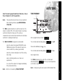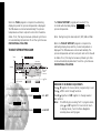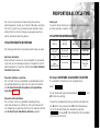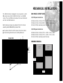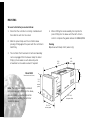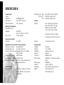
1
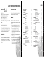
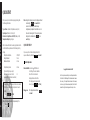
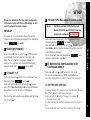
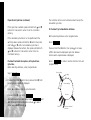
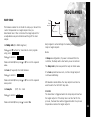
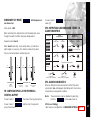
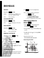
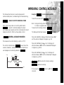
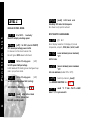
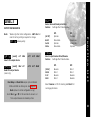
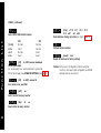
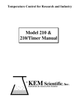
Operating Manual
CAL Controls
Temperature Controllers
CAL 3300 and 9300
Autotune Temperature
Controllers
CAL Controls Ltd
Bury Mead Road, Hitchin, Herts, SG5 1RT. UK
Tel: + 44 (0)1462-436161 Fax: + 44 (0)1462-451801
email: [email protected]
http://www.cal-controls.com
CAL Controls Inc
1580 S.Milwaukee Avenue, Libertyville, IL 60048. USA
Tel: (847) 680-7080 Fax: (847) 816-6852
000M01/33007/3/0898
CAL Controls
Temperature Controllers
INDEX
SAFETY AND WARRANTY INFORMATION
ULTIMATE SAFETY ALARMS
Designed for use:
UL873 - only in products where the acceptability is
determined by Underwriters Laboratories Inc.
EN61010-1 / CSA 22.2 No 1010.1 - 92
To offer a minimum of Basic Insulation only.
Suitable for installation within Catagory II and III and Pollution
Degree 2.
Do not use SP2 as the sole alarm where personal injury or
damage may be caused by equipment failure.
All functions are front selectable, it is the responsibility of
the installing engineer to ensure that the configuration is
safe. Use the program lock to protect critical functions from
tampering.
A1
SAFETY & WARRANTY
FUNCTIONS MENU
QUICK START
Quick Start Set-up
INTRODUCTION
The controllers
OVERVIEW
Installation
Set-up
Autotune
Cycle-time
SET-UP
Power-up
Select input sensor
Select display units
Allocate output device
Enter initial configuration
Set main setpoint
MENU NAVIGATION
Using program mode
AUTOTUNE
Tune program
Tune at setpoint program
PROPORTIONAL CYCLE-TIME
Cycle-time selection methods
Cycle-time recommendations
Autotune calculated cycle-time
PROGRAMMER
Ramp-Soak
A1
A3
1a
2
2
3
3
3
3
4
5
5
5
5
5
5
5
6
6
7
7
8
9
9
9
9
11
11
SECOND SETPOINT (SP2)
SP2 as an alarm
SP2 subsidiary mode
SP2 as a proportional output
SP2 alarm condition table
SP2 alarm annunciator
ERROR MESSAGES
Recommendations
Autotune data in tECH
IMPROVING CONTROL ACCURACY
Using ChEK accuracy monitor
FUNCTION LIST
Level 1
Level 2
Level 3
Level 4
OUTPUT OPTIONS
ADVANCED SETTINGS
Heat Cool strategy
Calibration to other instrument
Linear input calibration
MECHANICAL INSTALLATION
DIN panel cut-outs
Minimum spacing
Mounting
ELECTRICAL INSTALLATION
General requirements
Connection diagrams
INPUT/SENSOR SELECTION
SPECIFICATION
12
12
13
13
13
13
14
14
14
15
15
16
16
18
19
21
22
23
23
24
25
27
27
27
28
29
29
30
31
32
I n d e x
CONFIGURATION
W a r r a n t y
It is the responsibility of the installation engineer to ensure
this equipment is installed as specified in this manual and is
in compliance with appropriate wiring regulations.
CAL Controls warrant this product free from defect in
workmanship and materials for three (3) years from date of
purchase.
1 Should the unit malfunction, return it to the factory. If
defective it will be repaired or replaced at no charge.
2 There are no user-servisable parts in this unit. This
waranty is void if the unit shows evidence of being
tampered with or subjected to excessive heat, moisture,
corrosion or other misuse.
3 Components which wear, or damage with misuse, are
excluded e.g. relays.
4 CAL Controls shall not be responsible for any damage or
losses however caused, which may be experienced as a
result of the installation or use of this product.
CAL Controls liability for any breach of this agreement shall
not exceed the purchase price paid E. & O.E.
a n d
SEE ELECTRICAL INSTALLATION P29 & P30
WARRANTY
S a f e t y
INSTALLATION
A2
FUNCTIONS MENU
Process temperature (PV)
or setpoint (SP)
it
y
ex
pla
.5)
todis
ity t (0
au
itiv dEr.
m
arm
ing (6)
s
l
a
g
;
a
n
r
k
3
g
ra 32
Y
se .0 x
Lve
loc LEV
-A on
pro ; StA
tive to 1
y a 1 to
le
le
rity E;
ab Off;
pla dir;
ab Auto
riva 0.1
cu non
s
s
s
e
i
i
i
e
D
D
S
D
D
LL
;A
*
u
.2r
d.2
2i
1d
;1
1i.
f/s
2i;
.2d
or
2r;
e *
e (
.
.
u
r
s
t
c
c
n
t
i
i
s
1
1
D ;1
nt sens
t d;
u C;
ale
E
en
e
ev SSd
ev ; rlY
u
o
L
n
d
d
S
tp 2
tm
tm
l sc tor
P
ut rlY;
ut SSd
urn dn.
O/ ; 1i.2
i
ou ; 1d.
jus 25% r ful
jus 25%
p
p
b
t
t
d
d
;
e
e
;
;
r
o
o
on on
u
a
u
o
n
A
C
E
E
t
t
d
rs
rs
ro 0.0 sens
an 0.0
ve 1n.2
t M Off;
ve 1r.2
nso uP.S
1 o non
2 o non
Re
Se
Re
SP
Sp
SP
Ze
Se
ly)
d
rea
on
;
Ct3
2;
2
n
a 1; Ct S; oS
g
t
e
r
a
t
rsio it
d
o
L
e D tb; C S1; u re ve lt un
nit i; lo
n
AL
o
u
C
u
o
h
a
M
T
s
E;
T
ftw Con
ad VAr;
ad CtA; Ct4;
SE non
So
RE
Re
Re
LEVL 3 SP1.D SP2.D BURN REU.D REU.L SPAN ZERO CHEK READ TECH UER
CONFIGURE OUTPUT
SAFETY SETTINGS
C A L I B R AT I O N
Second setpoint
(SP2)
RSET
INSTRUMENT ADJUSTMENTS
P E R F O R M A N C E D ATA
r
l
d;
o;
so
na
An
t.h
%
tio
sen
nly
;b
r
e ld; L
%
%
m x to le
ut opor
its Ar;
m n to
Lo ol
n ee
so
t % ad o
.
d
u
t
t
p
u
V
o
t
u
o
i
o
u
un ; b Et
u
o
e
a
i
a
m
t
r
m
en
h
tp re
ou pr
od .hi; d Lo; C
axi or m ull sc
ini or m
ts
lay C; oF rh; S
utp %
utp %
2 m tCH;
olu deg
u
ou 0%
al 0% only
m
p
s
m
o
m
o
P
V
s
s
s
,
p
e
0
0
u
f
S
e
i
l
1
;
2 ; d FS
1 to
L
le Sen or
le Sen sca
P2 to
an 10 e
10
y r 0.1
SP
SP
t in E
t d E; o Ph
SP
nd E;
ca
ca
it S 00
in nonE S.hi;
pla 1 or
t s 0.0 sens
co non nLin
t s 0.0 full
lec non
lec non PSi;
ad 0 to
1 m 0 to mod Limit 100
F
Lim 1
Se
Ma
Se
Se
Se
Dis
Se
Re
SP
LEVL 2 SP1.P HAND PL.1
PL.2
SP2.A SP2.B DISP HI.SC LO.SC INPT UNIT
MANUAL ADJUSTMENTS
SP2 MODES
RANGING
CONFIGURE INPUT
QUICK START ENTRY
)
f/s
in)
st
ec
)
.Sp
st
or
/hy sor
or
At
5s
1.5
5m
/Hy sens
sec
le
ur
t
sec
in) sen
n
ff
et)
t) in (
te) c (2
e
rK;
a
ch d (
ain
1)
a
e
a
g
mi
r
k
s
81
e
oin ll sca
( 5%
f
res And
rat eg/ho
(
n/o o 81
/G 00% °F)
oa bAn
SP
s
e 0m
0
r
p
ar E; P
l
(
r
o
d
t
d
e
p
4
P
(
a
b
d
p
0
/of 1 to
u
t
n o 1 3.6
l
r .1
k
6
e rf
)
4
u
x
d
r tun
m
0
n
p
m
s
a
x
f
c
e
i
an to 2 8°F)
o
o
n
1
n
f
a
a
t
2
.
o
o
o
b
0
0
h
o
/
b
t
t
l
R
.
0
e
/o
)
0
le
e
;
o
9
C
e
e
P2 so
tim
ma 50% t = o
off off;
tive to 5
tive 1 to
int on
int 99
tim off; sec
un on
rop deg s (2°
t S en sca
ycl off;
tim 0 t
rop deg °C/1 gral f; 0.1
t(
.
jus +/– s full
tot oFF;
riva 0.5
riva Off;
f/
ak Off;
e Of
tpo Off;
fse 0 to (In
tpo 0 to
mp On;
2 C On.
1 P 0.1 (10
2 p 0.1
cle On. (20
So
Ra
SP
De
Ad
Se
Int
Of
Au
Se
De
SP
SP
Cy
LEVL 1 TUNE BAND INT.T DER.T DAC
Level C only visable
when COMMS
Option fitted
SP1 SETTINGS
CYC.T OFST SP.LK SPRR SPRN SOAK SET.2 BND.2 CYC.2
PROGRAMMER SETTINGS
SP2 SETTINGS
To
To
To
To
To
To
To
enter or exit program mode:
scroll through functions:
change levels or options:
view setpoint:
increase setpoint:
decrease setpoint:
reset an alarm or fault condition:
Notes:
Press ▲ ▼ together for 3 seconds
Press ▲ or ▼
Press ✱ ▲ together or ✱ ▼ together
Press ✱
Press ✱ ▲ together
Press ✱ ▼ together
Press ▲ ▼ together briefly
If in difficulty by becoming “lost” in program mode, press ▲ and ▼
together for 3 seconds to return to display mode, check the
INSTRUMENT ADJUSTMENTS above and try again.
PROGRAM ENTRY
s
s
dre
ad
nt 55
e
2
m
tru 0 to
Ins
:
00
O1
48
18
0: k2
ty
0
at 8E1:
9
4
e :2 :1
m
tivi on
t
r
1
a
:
o
r
ac
f
0
1
0
Rx Off;
ud 120 960 Data 18n
Tx/
Ba
LEVL C ADDR BAUD DATA DBUG
A3
Main setpoint
(SP1)
USER-PROTECTED SETTINGS
➔
KEY ✱ ▼ OR ✱ ▲ TOGETHER TO CHANGE LEVELS OR OPTIONS
F u n c t i o n s
LEVL 4 LOCK PROG NO.AL DIS.S DER.S
Range of Adjustment shown in red under
description. If applicable, factory settings shown
in bold.
* Note: Dual Relay and Dual SSd Output Options
Models 3311/9311 and 3322/9322 have their
outputs pre-configured. (see page 22)
➔
M e n u
2
LEV
COMMS SETTINGS
KEY ▼ ▲ TO VIEW FUNCTIONS
When in program mode, after 60 seconds of key inactivity the
display will revert to either INPT nonE or, if the
initial configuration has been completed, the measured value.
Any settings already completed will be retained.
QUICK START
After power-up the controller requires programming with
the following information:
Q u i c k
S t a r t
Type of Sensor (See list of temperature sensors p.31)
Operating unit (See list of units p.18)
Allocation of Output Device to SP1/SP2 (Relay or SSd)
Temperature Setpoint eg. Degrees
When the above information has been programmed into the
controller it will be operational with the following factory
settings.
Proportional band/Gain
10ºC/18ºF
Integral time/Reset
5 mins
Derivative time/Rate
25 secs
Proportional cycle-time
20 secs
(Typical setting for relay output)
DAC Derivative approach control
1.5
(Average setting for minimum overshoot)
NB: Please note that in the manual, functions are reversed
out from a black background and options are shown in
bold italic;
eg. TUNE and ParK
1a
Note: In this manual the letter k is represented by the
character K
Note: During the following procedure the display will revert
to alternating INPT and nonE after 60
seconds of key inactivity, but will retain any
settings already completed. Should this occur, or in
the event of becoming ‘lost’ in the program, please
start again from the alternating INPT and
nonE display.
QUICK START SET-UP
On power-up the controller will display the self test
sequence followed by alternating INPT and nonE
1 Select input sensor.
Press and hold ✱ and use the ▲ or ▼ buttons to
scroll through the sensor selection
list until the correct sensor is
displayed. Release the buttons.
The display now alternates selected
sensor type (eg. INPT and Tc.S )
Press ▲ once
The display will now alternate UNIT
and nonE
Copyright CAL Controls Ltd. 1997
Not to be reproduced without prior written permission from
CAL Controls Ltd. Whilst every effort has been made to ensure
the accuracy of the specifications contained in this manual,
due to our policy of continuous develpment, CAL Controls Ltd
reserves the right to make changes without prior notice.
QUICK START
2 Select unit.
4 To enter initial configuration into controller
memory
Press ▲ once
The display will now alternate
SP1.D and nonE
Note:
both ▲ and ▼ buttons for 3 seconds. The
display will now alternate ParK and
measured variable (temperature)
(eg. 23 ) ParK is displayed
because a setpoint has not yet been
entered.
To display setpoint
Press and hold ✱ The display will now alternate 0 and unit
(eg. °C )
Dual Relay and Dual SSd Output Options
To enter setpoint
Models 3311/9311 and 3322/9322 have
Press and hold ✱ and use ▲ button to increase or ▼ button
to decrease the reading and scroll to
required setpoint value. (The digit roll-over
rate increases with time).
their outputs pre-configured. (see page 22)
Press and hold ✱ and use the ▲ or ▼ buttons to select
SSd or rLY as required. The controller
will now alternate selected output device
(e.g. SP1.D and SSd).
S t a r t
3 Select SP1 (Main setpoint output device)
Press and hold
Q u i c k
Press and hold ✱ and use the ▲ or ▼ buttons to
scroll through the unit selection list
until the correct unit is displayed.
Release the buttons.
The display will now alternate
selected unit (eg. UNIT and°C ).
THE CONTROLLER IS NOW OPERATIONAL
WITH FACTORY SETTINGS
Note: For precise control of an application the controller
may need to be TUNED. Please study section
headed FUNCTIONS and OPTIONS before moving to
the section on AUTOTUNE.
1b
INTRODUCTION
I n t r o d u c t i o n
THE CONTROLLERS
CALCOMMSTM uses the MODBUS® protocol via either a fully
isolated RS232 or RS485 link depending on the number of
instruments and the transmission distances involved in the
application.
A users manual is supplied with the comms option. For more
information contact CAL. For details, see rear cover.
The CAL 3300 1/32 DIN and the CAL 9300 1/16 DIN miniature
controllers share the same PID control strategy and features
while giving the user the flexibility of a choice of panel
format. Control can be optimised with a single shot autotune
either on initial warm-up or at setpoint. A second setpoint
can be configured in a variety of alarm modes or PID HeatCool strategy. A programmer offers a single ramp to setpoint
with a choice of timed soak period before switching off the
output.
Control of non temperature processes is achieved by the
provision of linear input ranges and scaling in commonly
used engineering units.
Serial communication is available as an option on both
controllers, and the easy to use CALCOMMSTM is a graphic
2
WINDOWSTM based software package designed for PC
supervision of up to 32 instruments, for remote adjustment,
configuration, cloning, saving and retrieving settings to files
and logging and charting in real time.
It is suggested that users read the OVERVIEW section of this
manual before any installation or setting-up procedures are
undertaken.
Note: The controller will not be operational until either the
QUICK-START or SET-UP procedure has been
completed.
NB: Please note that in the manual, functions are
reversed out from a black background and options are
shown in bold italic;
eg. TUNE and ParK
OVERVIEW
AUTOTUNE
The Model 3300 controller is designed to be mounted in a
1/32 DIN panel cutout and the Model 9300 in a 1/16 DIN
cutout. See the INSTALLATION section.
To precisely control an application the controller will need
to be ‘tuned’ using the built-in ‘AUTOTUNE’ feature.
Autotune ‘teaches’ the controller the main characteristics of
the process and ‘learns’ by cycling the output on and off.
The results are measured and used to calculate optimum PID
values which are automatically entered in the controller
memory.
SET-UP
After installation the controller requires programming with
the following information:
Type of Input Sensor
Operating unit (C or F etc)
Type of Output Device
Temperature Setpoint
Note: The controller will not be operational until this
information is entered.
When the above information has been programmed into the
controller it will be operational with the following factory
PID (proportional band, integral time, derivative time)
settings.
Proportional band/Gain
10°C/18°F
Integral time/Reset
5 mins
Proportional cycle-time
20 secs
Derivative time/Rate
25 secs
DAC Derivative approach control
1.5
During AUTOTUNE the optimum cycle-time is calculated but
is not automatically implemented. The cycle-time requires
manual acceptance unless pre-selected.
To ensure good control over a wide range of applications
two versions of the Autotune program are provided, TUNE
and TUNE AT SETPOINT.
O v e r v i e w
INSTALLATION
The TUNE method normally achieves the best results.
Starting with the load cool, tuning occurs during warm-up
preventing overshoot. This method of tuning is
recommended.
The TUNE AT SETPOINT method is used for specialist
applications. eg. Heat-cool, multizones and processes below
100°C/200°F. During the tuning cycle some overshoot occurs
because the tuning cycle is at set point.
The DAC setting is not re-calculated.
3
CYCLE-TIME
O v e r v i e w
The choice of cycle-time is influenced by the external
switching device or load. e.g. contactor, SSR, Valve. A
setting that is too long for the process will cause oscillation
and a setting that is too short will cause unnecessary wear
to an electro-mechanical switching device.
Cycle-time selection methods
The following methods of cycle-time selection may be used:
Autotune calculated
After Autotune has been run and completed the calculated
cycle-time can be manually accepted or adjusted to suit the
switching device. For selection method see Select Autotune
Calculated Cycle-time.
Pre-select autotune cycle-time
The controller can be programmed to automatically accept
the calculated Autotune cycle-time. For selection method
see Pre-Select Automatic Acceptance of Any Autotune
Cycle-time.
Pre-select before autotune
The controller can be programmed manually with any
cycle-time between 0.1 and 81 sec. This cycle-time will not
be changed by any Autotune functions. For selection
method see Pre-Select Cycle-time Before Autotune.
4
Factory set
To use the 20 sec factory set cycle-time no action is
needed whether Autotune is used or not.
Further information can be programmed into the controller,
see SECOND SETPOINT, RANGING AND SETPOINT LOCK,
IMPROVING CONTROL ACCURACY
Functions and options
The facilities of the controller are selected from the multilevel menu using the front panel mounted buttons.
Note: It is advisable to study this section before any
programming is undertaken.
Each level within the multi-level menu offers different
functions, see FUNCTIONS MENU for menu of main
functions. Each function has a range of user selections or
options, see FUNCTION LIST for functions and options
details.
Note: Please note that in the manual, functions are
reversed out from a black background and options
are shown in bold italic;
eg. TUNE and ParK
The controller has two modes, program mode and
operating mode. When in program mode the controller can
be programmed with settings and functions to suit the
application. When in operating mode the controller uses the
setting and functions entered in the program mode to
control the application and also displays the process
variable (temperature). For full details on how to program
the controller see VIEWING AND SELECTING FUNCTIONS.
Note: In this manual the letter k is represented by the
character K
SET-UP
This section details the four step initial configuration
that enables control with factory PID settings to start,
once the setpoint has been entered.
POWER-UP
On power-up the controller will display the self test
sequence and brief display blanking and then alternately
display INPT and nonE
Press and hold ✱ and use either the ▲ or ▼ buttons to
scroll through the sensor selection (see table p.31).
When the correct sensor is displayed, release the
buttons. The controller will now alternately display
selected sensor type INPT and eg. tc.S
2 TO SELECT °C/°F
Press and release the ▲ button, the controller will now
alternately display UNIT and nonE.
Press and hold the ✱ button and using the ▲ button
select °C, °F, Bar, PSI, Ph, Rh or SEt as required. Release
the buttons when the correct unit is displayed.
The controller will now alternately display selected range
(eg. ºC) and unit.
Note:
Dual Relay and Dual SSd Output Options
Models 3311/9311 and 3322/9322 have their
outputs pre-configured. (see page 22)
Press and release the ▲ button, the controller will now
alternately display SP1.D and nonE.
Press and hold the ✱ button and using the ▲ button
select SSd or rLY as required. Release the buttons when the
correct device is displayed.
The controller will now alternately display SP1.D and
selected output device (eg. SSd).
4 TO ENTER INITIAL CONFIGURATION INTO
CONTROLLER MEMORY
S e t - u p
1 SELECT INPUT SENSOR
3 TO SELECT SP1 (Main setpoint output device)
Press and hold both ▲ and ▼ buttons for 3 seconds.
The process temperature (e.g. 23°C) and ParK will be
alternately displayed as no setpoint has yet been selected.
TO SET THE MAIN SETPOINT
To display the setpoint, press and hold the ✱ button. °C and
0 or °F and 32 will be alternately displayed.
Press and hold the ✱ button. Press ▲ to increase or ▼
to decrease the setpoint.
The main setpoint LED will flash indicating that SP1 output is
ON.
The controller will now be set with the factory PID settings.
5
M e n u
N a v i g a t i o n
MENU NAVIGATION
6
The facilities of the controller are selected from the multilevel menu using the front panel mounted buttons.
Each level within the multi-level menu offers different
functions, see FUNCTIONS MENU for menu of main
functions. Each function has a range of user select or input
options, see FUNCTION LIST for functions and options
details.
The controller has two modes, program mode and
operating mode. When in program mode the controller can
be programmed with settings and functions to suit the
application. When in operating mode the controller uses
the setting and functions entered in the program mode to
control the application.
USING PROGRAM MODE
Note: The controller will auto-exit program mode after 60
seconds of inactivity.
To enter program mode from normal operating mode
Press and hold both ▲ and ▼ buttons for at least 3
seconds.
Release the buttons together when the function TUNE
is displayed, this is the program entry point.
The controller will now alternately display the function and
option (setting of that function), e.g. TUNE and oFF.
To view function on the same level
Press ▲ or ▼ button once to view the next function.
Press and hold ▲ or ▼ buttons to scroll through functions.
To display the current option or value for a function
On release of ▲ or ▼ buttons, option alternates with the
function.
To change an option value or setting
Press and hold the ✱ button, then press ▲ to increase or ▼
to decrease the value or select the next option.
Note: Check the new option value before moving to
another function or exiting program mode.
To change levels
Press and hold ▼ to scroll through the functions until LEUL is
displayed. Release ▼ to display current level. Press and hold
the ✱ button, then press ▲ to increase or ▼ to decrease
the level. Release buttons when required level is obtained.
To exit program mode
Press and hold both ▲ and ▼ buttons for at least 3 seconds.
Note: Control commences with any new instructions now
entered in the memory.
REMINDER OF INSTRUMENT ADJUSTMENTS
Press ▲ ▼ together for 3 seconds for program entry or exit.
Press ▲ or ▼ to scroll through functions.
Press ✱ ▲ together or ✱ ▼ together to change levels or alter
options.
Note: If in difficulty by becoming “lost” in program mode,
press ▲ and ▼ together for 3 seconds to return
to display mode, check the Menu Navigation
summary above and try again.
AUTOTUNE
Select the most appropriate method of Autotune , Tune or
Tune at Setpoint, to suit the application.
Note:
TUNE PROGRAM
Temp
Setpoint
The proportional cycle-time can be pre-selected
before starting Autotune, see PROPORTIONAL
CYCLE-TIME.
Tuning
DAC
PID
TUNE
Cycle
75% SP
New PID
values
entered
11/4 on/off tuning
cycles
The TUNE program should be run with the load cool. The
output is cycled at 75% of the setpoint value to avoid any
overshoot during the tuning cycle. The warm-up
characteristics are monitored and set DAC which minimises
overshoot on subsequent warm-ups.
Enter program mode and select TUNE
The TUNE AT SETPOINT program is recommended:
The controller will alternately display TUNE and oFF.
when the process is already hot and the cooling
rate is slow;
when controlling multi-zone or heat-cool
applications;
to re-tune if the setpoint is changed substantially
from previous Autotune.
Note:
dAC is not re-tuned by TUNE AT SETPOINT.
Time
(100% output)
Press and hold ✱ and press ▲ once,
The controller will alternately display TUNE and on.
A u t o t u n e
when the setpoint is below 100°C/200°F, where
TUNE’s tuning cycle at 75% setpoint may be too
close to ambient to produce good results;
Start TUNE
Exit program mode.
The TUNE program will now start. The controller will
alternately display TUNE and the process temperature
as it climbs to setpoint.
Note:
During tuning, the main setpoint (SP1) LED will flash.
7
A u t o t u n e
When the TUNE program is complete the alternating
display stops and the process temperature is displayed.
The PID values are entered automatically. The process
temperature will rise to setpoint and control should be
stable. If not, this may be because optimum cycle time is
not automatically implemented. To set the cycle time see
PROPORTIONAL CYCLE-TIME.
TUNE AT SETPOINT PROGRAM
Start TUNE AT.SP
Temp
Overshoot
during tuning
Note: During tuning the main setpoint (SP1) LED will flash.
When the TUNE AT SETPOINT program is complete the
alternating display stops and the process temperature is
displayed. The PID values are entered automatically. The
process temperature will rise to setpoint and control should
be stable. If not, this may be because optimum cycle time
is not automatically implemented. To set the cycle time see
PROPORTIONAL CYCLE-TIME.
Setpoint
Prop band
13/4 on/off tuning
cycles
Tuning
PID
New PID
values
entered
Time
(100% output)
Enter program mode and select TUNE
The controller will alternately display TUNE and oFF.
Select TUNE At.SP.
The controller will alternately display TUNE and At.SP.
8
The TUNE AT SETPOINT program will now start. The
controller will alternately display TUNE and the
process temperature.
Exit program mode.
REMINDER OF INSTRUMENT ADJUSTMENTS
Press ▲ ▼ together for 3 seconds for program entry or exit.
Press ▲ or ▼ to scroll through functions.
Press ✱ ▲ together or ✱ ▼ together to change levels or
alter options.
Note: If in difficulty by becoming “lost” in program mode,
press ▲ and ▼ together for 3 seconds to return
to display mode, check the Menu Navigation
summary above and try again.
PROPORTIONAL CYCLE-TIME
CYCLE-TIME SELECTION METHODS
The following methods of cycle-time selection may be used:
Pre-select Autotune cycle-time
The controller can be programmed to automatically accept
any calculated Autotune cycle-time. For selection method
see Pre-Select Automatic Acceptance of Any Autotune
Cycle-time, page 10.
Pre-select before Autotune
The controller can be programmed manually with any
cycle-time between 0.1 and 81 sec. This cycle-time will not
be changed by any Autotune functions. For selection method
see Pre-Select Cycle-time Before Autotune, page 10.
CYCLE-TIME RECOMMENDATIONS
Output
Device
Factory
Setting
Recommended
Minimum
Load max
(resistive)
Internal relay
rLY/rLY1
Internal relay
rLY2
Solid state
drives
SSd/SSd1/SSd2
20 seconds
10 seconds
2A/250 Vac
20 seconds
10 seconds
1A/250 Vac
20 seconds
0.1 seconds
Externally
fitted SSR
(n/a)
To Select AUTOTUNE CALCULATED CYCLE-TIME
On completion of Autotune enter program mode.
Select CYC.T
The controller will now alternately display CYC.T and
20 (the factory setting).
To view the calculated optimum cycle-time press and hold
the ✱ button then press and hold ▼ until indexing stops.
The controller will display the calculated cycle-time
CYC.T and eg. A 16. This indicates that the calculated
cycle-time is 16 seconds.
c y c l e - t i m e
Autotune calculated
After Autotune has been run and completed the calculated
cycle-time can be manually accepted or adjusted to suit the
switching device. For selection method see Select Autotune
Calculated Cycle-time.
Factory set
To use the 20 sec factory set cycle-time no action is needed
whether autotune is used or not.
P r o p o r t i o n a l
The choice of cycle-time is influenced by the external
switching device or load. eg. contactor, SSR, valve. A setting
that is too long for the process will cause oscillation and a
setting that is too short will cause unnecessary wear to an
electro-mechanical switching device.
9
To Pre-Select Cycle-time Before Autotune
Before selecting Autotune, enter program mode.
If the calculated cycle-time is not compatible with the
switching device press and hold the ✱ button then press
and hold ▲ or ▼ until a more suitable cycle-time is
displayed. Release the buttons, then press and hold both
▲ and ▼ buttons for 3 seconds to enter it into the
controllers memory.
Pre-Select Automatic Acceptance of Any Autotune
Cycle-time
Before selecting Autotune, enter program mode.
Select CYC.T
Select CYC.T
Press and hold the ✱ button, then press ▲ to increase
or ▼ to decrease the displayed cycle-time. Release
buttons when required value is displayed.
Select TUNE or index to another function then exit
program mode.
Factory setting
✱▲
Press and hold the ✱ button then press and hold ▼ until
indexing stops and A - - is displayed.
Press and hold ▼ to scroll to TUNE
The controller will now alternately display TUNE and
oFF. Press and hold the ✱ button and use ▲ to select
either on or At.SP. Release ▲.
Manual settings
✱▼
Seconds
.1
8
O
N
.O
F
A-
Note: A - - indicates that no cycle-time exists.
0
10
If this cycle-time is suitable press and hold both ▲ and ▼
buttons for 3 seconds to enter it into the controllers
memory.
The controller will now run Autotune and will accept the
calculated cycle-time.
2
Proportional
cycle-time
Proportional Cycle-time (continued)
0
ON/OFF
Autotune calculated
cycle-time
1
PROGRAMMER
RAMP-SOAK
Deg.
This feature enables the controller to ramp up or down from
current temperature to a target setpoint at a predetermined rate. It then controls at the target setpoint for
an adjustable soak period before switching off the heat
output.
Target
setpoint
Deg.
Soak
Ramp °/hour
Ramp °/hour
Target
setpoint
Time
Soak
Time
Exit program to enter settings into memory and commence
ramp to target setpoint.
Press ▲ and ▼ buttons for 3 seconds to enter program
entry point TUNE
Notes
Press ▲ to scroll to SPRR
Press and hold ✱, then press ▲ or ▼ to scroll to required
value.
Set Soak (if required) 0 to 1440 minutes
Press ▲ to scroll to SOAK
Press and hold ✱, then press ▲ or ▼ to scroll to required
soak period.
Set Ramp On
(Off) : On : hold
Press ▲ to scroll to SPRN
Press and hold ✱, then press ▲ to select On
In Ramp on configuration, if power is removed from the
controller, the Ramp will re-start when power is restored.
The Ramp hold option suspends the ramp at its last value.
If no Soak period has been set, control at target setpoint
continues indefinitely.
P r o g r a m m e r
Set Ramp rate (0 to 9995 deg/hour)
SP2 deviation alarms follow the ramp setpoint and can be
used to alarm “out of limits” ramp rate.
WARNING
The Soak timer is triggered when the ramp setpoint reaches
the target setpoint. If the ramp rate is set too fast for the
process, the Soak timer will be triggered before the process
temperature reaches the target setpoint.
11
S e c o n d
S e t p o i n t
SECOND SETPOINT (SP2)
The second setpoint SP2 can be used to trigger an alarm
or as a proportional control output.
dV.hi
sets off alarm signal when temperature rises above
a pre-set temperature above the setpoint.
TO CONFIGURE SP2 AS AN ALARM
dV.Lo
sets off alarm signal when temperature falls below
a pre-set temperature below the setpoint.
bAnd
sets off alarm signal when temperature rises above
or falls below a pre-set temperature above or
below the setpoint.
Deviation
band alarm
FS.hi
sets off alarm signal when the temperature rises
above setpoint to a pre-set temperature above
scale minimum.
✱
FS.Lo
sets off alarm signal when the temperature falls
below setpoint to a pre-set temperature above
scale minimum.
Enter program mode.
Select level 2 then SP2.A , followed by the required
option below:
Deviation
high alarm
Deviation
low alarm
Alarm
state
✱
SP
setpoint
Y°
SP
setpoint
SP
setpoint
Y°
✱
Y°
Y°
✱
Select level 1 and select SET.2 and set the required
setpoint value (y°).
Y°= SP2
set value
If the factory set hysteresis 2.0°C/3.6°F is unsuitable:
Full scale
high alarm
Full scale
low alarm
Index to BND.2 and adjust the setting.
Check CYC.2 is set to on.oF (for alarm).
✱
SP
setpoint
SP
setpoint
Exit program mode. SP2 is now operational as an alarm.
✱
CooL see heat-cool configuration, page 23.
12
Y°
Y°
SUBSIDIARY SP2 MODE: SP2.B Latch/sequence or
non-linear cool.
Latch alarm LtCh
SP2 OUTPUT AND LED INDICATION STATES - IN
ALARM CONDITION
Alarm type
Deviation
Sequence alarm hoLd
ON-OFF
operating mode
SP2
Output state
SP2
LED state
Proportional
operating mode
SP2
Output state
SP2
LED state
DV.HI
When hoLd is selected, in any alarm mode, it prevents an
alarm signal on power-up. The alarm is enabled only when
DV.LO
BAND
BAND
: on-off mode only
Full scale
the process temperature reaches setpoint.
S e c o n d
When activated, the alarm latches until manually reset, even
though the alarm condition may have disappeared.
In level 1 select SET.2 and then set the setpoint (SP2)
value (y°).
FS.HI
FS.LO
SP
setpoint
Y°
SP
setpoint
SP
setpoint
SP
setpoint
Y°
Strategy
✱
✱
Without sequence
alarm
Alarms on
power up
Output ON
(Relay or SSd energised)
Alarm
enabled
Alarm operates
normally
TO CONFIGURE SP2 AS A PROPORTIONAL
CONTROL OUTPUT
In level 2 select SP2.A , then select the required option.
In level 1 select BND.2
proportional band.
LED ON
SP2 ALARM ANNUNCIATOR
With sequence alarm
No alarm on
power up
Output OFF
(Relay or SSd de-energised)
and then set the required
When an SP2 alarm mode is selected in SP2.A the alarm
annunciator -AL- is displayed, alternating with the process
temperature, during alarm condition.
Note:
S e t p o i n t
Temperature above setpoint
COOL
The annunciator may be disabled by selecting
function NO.AL , option on in level 4.
SP2 in cool strategy
(See heat-cool configuration in ADVANCED SETTINGS page 23).
13
ERROR MESSAGES
SENSOR FAULT
Action:
Check sensor/wiring
NON-VOLATILE MEMORY ERROR
Display flashing:
Action:
DATA and FaiL
De-power briefly. Replace unit if problem
persists
MANUAL POWER ERROR
Display flashing:
DATA and FaiL
SP1 set to ON/OFF in CYC.t
Action:
Select proportional mode
IMMEDIATE FAIL ON AUTOTUNE START
Display flashing: (setpoint), TUNE and FaiL
1. No setpoint entered
Action:
Enter setpoint
2. SP1 set to ON/OFF in CYC.T
Action:
Select proportional mode
Action: 1. Change the conditions. eg. raise setpoint
2. Try TUNE At.SP
3. Check SP1.P percentage power
(see IMPROVING CONTROL ACCURACY)
4. If the error message persists, call CAL for advice.
READING AUTOTUNE TUNING CYCLE
RESULTS IN TECH
1. Index to TECH , release ▲ or ▼, display will
alternately display TECH and Ct.A
2. Press and hold ✱, the display will alternate Ct.A and value
(eg. 10.4)
3. Keep ✱ pressed and press ▲ once, the display Ct.B and
value (eg. 19.6)
4. Repeat step 3 above to view:
Ct 1, Ct 2, Ct 3, Ct 4, oS 1, uS and oS 2.
Autotune tuning data and limits
Temp
Ct 1
TUNE
Cycle
75% SP
The thermal characteristics of the load exceed the Autotune
algorithm limits. The failure point indicated by any display
Ct A
FAIL LATER DURING AUTOTUNE CYCLE
14
oS 2
oS 1
Tuning
Note: To reset and clear error press ▲▼ together briefly to
cancel message.
PID
DAC
Setpoint
uS
Ct 4
thermocouple burnout RTD/Pt100 open or
short circuit or negative over-range.
Ct 3
Indicates:
Ct 2
INPT and FaiL
Ct b
E r r o r
M e s s a g e s
Display flashing:
0.0 in TECH eg. Ctb = 0.0 see diagram below.
New PID
values
entered
Start TUNE
Time
(100% output)
IMPROVING CONTROL ACCURACY
Using the CHEK Control accuracy monitor
To start the monitor select CHEK on
SP1.P
READ SP1 OUTPUT PERCENTAGE POWER
Poor control may be due to incorrectly sized heaters.
SP1.P (Level 2) constantly displays the output
percentage power applied, which at normal setpoint should
ideally be within 20 - 80% to achieve stable control.
CONTROL ACCURACY MONITOR
The display will alternate between READ and Var°
Press and hold ✱, the display will alternate between Var°
and the variance displayed in degrees (e.g. 0.6)
This measures the control stability, to within 0.1 °C/°F.
The monitor is started using CHEK (Level 3) and the
variance (deviation), maximum and minimum temperatures
are displayed and constantly updated in READ
Maximum
hi°
Press and hold ✱ and press ▲ once, the display will
alternate between VAr° and the minimum Lo° displayed
in degrees (e.g. 319.7)
Variance
VAr° ±0.1°
CHEK oFF stops monitor retaining readings
Lo°
Minimum
CHEK
on resets readings.
Time
On de-powering CHEK resets to oFF and READ
is zeroed.
Accuracy
Temp
Press and hold ✱ and press ▲ once, the display will
alternate between VAr° and the maximum hi° displayed
in degrees (e.g. 320.3)
Control
CHEK
Note: During monitoring either return to normal operation
or remain in program mode.
To view monitor readings: index to READ
Improving
The following functions are to assist engineers with
machine development, commissioning and troubleshooting.
15
FUNCTION LIST
The functions and options are available in four levels.
Note:
A Functions Menu is shown on the cover fold-out
INT.T
oFF
0.1 to 60 minutes
[5.0]
SP1 integral time/reset
Auto-corrects proportional control offset error
F u n c t i o n
L i s t
LEVEL 1
16
Function
Options
[Factory settings] shown in brackets
Too short
(overshoots and oscillates)
Too long
(slow warm up and response)
SELECT AUTOTUNE
TUNE [oFF] on ParK At.Sp
DER.T
Used to switch the Autotune feature on and off, to select
ParK or Autotune at setpoint.
ParK temporarily turns the output(s) off. To use select ParK
and exit program mode. To disable re-enter program at
TUNE and select oFF.
oFF
1 - 200 seconds
[25]
SP1 derivate time/rate
Suppresses overshoot and speeds response to disturbances
*
Too short
(slow warm up and response,
under corrects)
* disturbance
Too long
(oscillates and over corrects)
SP1 OPERATING PARAMETERS
BAND
0.1 to * °C/°F
[10ºC/18ºF]
SP1 proportional band/Gain or Hysteresis
* 25% sensor maximum
Proportional control eliminates the cycling of on-off
control. Heater power is reduced, by time proportioning
action, across the proportional band.
Too narrow
(oscillates)
Too wide
(slow warm up and response)
increase BAND
decrease BAND
DAC
0.5 - 5.0 x bAnd
[1.5]
SP1 derivative approach control dAC
Tunes warm-up characteristics, independent of normal
operating conditions, by controlling when derivative
action starts during warm-up (smaller dAC value = nearer
setpoint).
Too small
(overshoots)
Too large
(slow stepped warm up)
LEVEL 1 (continued)
CYC.T
SP2 OPERATING PARAMETERS (see pages 12/13)
A - - on.oF 0.1 - 81 sec [20]
OFST
[0] to *
°C/°F
SP1 offset/manual reset
* ±50% bAnd. Applicable in proportional and ON/OFF
mode with integral disable: Int.t oFF.
SP.LK
[oFF]
on
0 to * °C/°F
[0]
BND.2
0.1 - * °C/°F
[2.0 °C/3.6°F]
Adjust SP2 hysteresis or proportional band/gain
(see CyC.2 setting)
* 25% sensor f/s
CYC.2
PROGRAMMER SETTINGS (see page 11)
Select SP2 ON/OFF or proportional cycle-time
Select on.oFF for ON/OFF mode, or the cycle rate of
SP2 output device for proportional mode.
[0] to 9995 deg/hour
SPRR
Sets the ramp rate
[on.oFF] 0.1–81 seconds
L i s t
Lock main setpoint
Locks the setpoint preventing unauthorised adjustment.
F u n c t i o n
SP1 proportional cycle-time (see pages 9/10)
Determines the cycle rate of the output device for
proportional control. Select on.oF for ON/OFF mode.
SET.2
Adjust SP2 setpoint
* Deviation Alarms DV.hi, DV.Lo, bAnd
25% sensor maximum (see figure 7).
* Full scale alarms FS.hi, FS.Lo
sensor range f/s (see figure 8)
on [oFF] hoLd
SPRN
Switches the ramp on or off, or hold at last ramp value
[oFF]
SOAK
Sets the soak time
0 to 1440 min
17
LEVEL 2
SP2.B
L i s t
F u n c t i o n
0 to 100 %
INPUT SELECTION AND RANGING
‘read only’
Read SP1 output percentage power
DISP
HAND
[oFF] 1 to 100 % (not in ON/OFF)
SP1 manual percentage power control
For manual control should a sensor fail.
Record typical SP1.P values beforehand.
PL.1
100 to 0 % duty cycle
[100]
100 to 0 % duty cycle
[sensor minimum] sensor maximum
°C/ºF
Set scale minimum (default 0°C or 32°F)
UNIT
18
Select input sensor [nonE]
(See SENSOR SELECTION table, page 31)
SP2 OPERATING MODES (see page 12/13)
[nonE] dV.hi dV.Lo bAnd
FS.hi FS.Lo Cool
Main SP2 operating mode
sensor minimum [sensor maximum]
°C/°F
LO.SC
INPT
SP2.A
0.1
Set full scale
[100]
Set SP2 percentage power limit (cooling)
[1]
Select display resolution: for display of process
temperature, setpoint, OFSt, Set.2, hi.SC, LoSC.
HISC
Set SP1 power limit percentage
Limits maximum SP1 heating power during warm-up
and in proportional band.
PL.2
LtCh hoLd nLin
Subsidiary SP2 mode: latch/sequence
Non-linear cool proportional band
MANUAL CONTROL MODES
SP1.P
[nonE]
nonE °C °F bAr Psi Ph rh SEt
Select °C/°F or process units
LEVEL 3
BURN
Sensor burn-out/break protection
Caution:
Settings affect fail safe state.
OUTPUT CONFIGURATION
Note:
[uP.SC]
dn.SC
1u.2d
1d.2u
SP1
Upscale
Downscale
Upscale
Downscale
SP2
Upscale
Downscale
Downscale
Upscale
REU.D
SP1.D
[nonE]
rLY
SSd
rLY1 rLY2 SSd1
Select SP1 output device
SP2.D
[nonE]
SSd rLY
Select output modes: Direct/Reverse
Caution:
Settings affect fail safe state.
rLY2 rLY1 SSd2
SP1
Reverse
Direct
Reverse
Direct
SP2
Direct
Direct
Reverse
Reverse
Dual Relay and Dual SSd output options Models
3311 and 3322 are factory set. See page 22
L i s t
Read SP2 output device
(read only)
[1r.2d]
1d.2d
1r.2r
1d.2r
F u n c t i o n
‘Read only’ after initial configuration. rSET ALL full
reset to factory settings required to change
SP1.D subsequently.
Select Reverse on SP1 for heating and Direct for
cooling applications.
Note: (when in initial configuration only)
Hold ✱ and ▲ or ▼ for 10 seconds to move to or
from output devices in shaded portion.
19
LEVEL 3 (continued)
[Ct A] CT b Ct 1 Ct 2 Ct 3
Ct 4 oS 1 uS oS 2
Read Autotune tuning cycle data (see figure, page 14)
TECH
REU.L
F u n c t i o n
L i s t
Select SP1/2 LED indicator modes
[1n.2n]
1i.2n
1n.2i
1i.2i
SP1
Normal
Invert
Normal
Invert
SP2
Normal
Normal
Invert
Invert
Software version number
RSET
[nonE]
ALL
Resets all functions to factory settings
[0.0] to ±25% sensor maximum
SPAN
Sensor span adjust
For recalibrating to a remote standard e.g. External
Meter, data logger. See ADVANCED SETTINGS page 24,25.
ZERO
[0.0]
to ±25% sensor f/s
Zero sensor error, see SPAn
CHEK
[oFF]
on
Select control accuracy monitor
READ
[Var]
hi
Lo
Read control accuracy monitor
20
VER
Caution: Note current configuration before using this
function, otherwise initial configuration and OEM
settings must be re-entered.
LEVEL 4
Access to level 4 is gained through VER
Press and hold ▲ and ▼ for 10 seconds.
Press ▼ to access following functions
in level 3.
NO.AL
Program security using Lock
[Auto]
StAY
Program mode auto-exit switch
Auto-exit returns display to normal if 60 seconds of key
inactivity, select StAY to disable
[oFF]
on
Disable SP2 alarm annunciator -ALSelect on to disable -AL-
Select from three Lock options:
DIS.S
Press and hold ✱, press ▲ to index.
locks level 3 and 4 only- Technical Functions.
LEV.2
locks levels 2, 3 and 4 only - Configuration and
Technical Functions.
ALL
✂
Note:
locks all functions (unrestricted LEVL, VEr,
TECH , SP.LK)
1 to 32
[6]
DER.S
0.1 to 1.0
[0.5]
Derivative sensitivity
L i s t
LEV.3
dir
Display sensitivity
dir = direct display of input
1 = maximum, 32 = minimum sensitivity
F u n c t i o n
Enter level 4 at Lock, release ▲ and ▼ together. Display
will alternate LOCK and nonE
PROG
Locked functions and options may be read.
IMPORTANT NOTE FOR OEM’s: For safety and to protect settings from tampering
USE THE SOFTWARE SECURITY LOCK.... THEN REMOVE THIS SECTION.
21
FACTORY SET OUTPUT OPTIONS
DUAL RELAY OR DUAL SSd OUTPUT MODELS
The table below details the factory set output options. rLY2
is a 1A electromechanical relay, and SSd1/SSd2 is an
identical second SSR drive output.
Product
Code
4
rLY1 (2A)
Note: Output device rLY/rLY1 is rated 2A
Output device rLY2 is rated 1A
Factory Option 3311/9311 offers the ability to change
the allocation of SP1 to terminals 5 and 6.
Terminals
3
Factory Options 3311/9311 and 3322/9322 preallocate SP1 to terminals 3 and 4.
5
6
rLY2 (1A)
3311/9311
To make this selection during the initial configuration in
either QUICK START (page 1b) or SET-UP (page 5), start from
step 3.
3 TO SELECT SP1 (Main setpoint output device)
SSd1
3322/9322
(+)
SSd2
(-)
(+)
(-)
QUICK START (page 1a) or SET-UP (page 5)
follow steps 1 and 2 ignore step 3 and proceed
straight to step 4.
22
From the alternating display SP1D and rLY1 press
and hold ✱ button then press the ▲ once to display rLY2.
ADVANCED SETTINGS
From cold (normal procedure on a new installation)
HEAT COOL STRATEGY CONFIGURATION
Level 1
Enter setpoint and allow the process to reach the setpoint
using factory settings for heating only.
Autotune at setpoint
Make the following pre-settings:
Plastics extruders where the material initially
needs heating, then cooling, when it begins to
heat itself exothermically due to pressure and
friction applied by the process.
The purpose of cool strategy is to maintain smooth control
of the process during transition from heating to cooling.
This is achieved by using PID control for heating and cooling
with the proportioning bands linked by an adjustable
deadband.
to 1.0 CYC.T to 10
Level 2
set
SP2.A to Cool
Level 1
set
TUNE to At.SP
Autotune will cause a temporary disturbance. Check that
the temperature has stabilised in heating mode before
running the process in cooling mode.
If regular temperature oscillations occur, change CYC.t to
optimum value. See page 9. To select Autotune Calculated
Cycle-time
Further adjustments – Cooling
Autotune uses the same calculated BAND value for
both SP1 (heating) and SP2 (cooling). In some processes,
regular temperature oscillations occur when cooling.
S e t t i n g s
Environmental test chambers used in rooms
where the ambient temperature swings above
and below the test temperature.
DAC
and CYC.2 to 10
Using SP2.A Cool option
Heat-Cool strategy is a feature that improves control of
processes that need heating and cooling, depending on the
conditions, for example:
set
A d v a n c e d
Before embarking on the Advanced Settings, please
familiarise yourself with the basic operation of the controller
as described in this manual. The following instructions
assume that the user understands how to make the initial
configuration, can navigate through the Function Menu and
successfully Autotune the controller in heating mode.
Make the following manual adjustment:
In level 1 double the value of BND.2
23
S e t t i n g s
A d v a n c e d
24
Heat Cool Strategy Configuration (continued)
CALIBRATION TO ANOTHER INSTRUMENT
If no improvement, return to the original value and;
If the controller and instrument readings are different, the
ZERO and/or SPAN function in Function
Menu Level 3 will require adjustment.
In level 1 halve the value of CYC.2
If the process hunts between heating and cooling, a
deadband setting may be needed. Enter a small value,
eg. 1 and observe the process. Increase the setting until
hunting stops.
Level 1 adjust value SET.2
Adjust ZERO to make an equal adjustment across the
full scale of the controller and SPAN to make a
correction when the error increases/decreases across the
scale.
1
Water cooled applications
Water cooled applications operating at temperatures greater
than 100°C may suffer from the non linear effect caused by
water turning to steam. This can be countered by the non
linear setting for SP2;
In level 2 set SP2.B to nL in
Multi zone applications
When tuning multi zone applications like extruders,
distortions due to thermal interaction between adjacent
zones can be minimised by running autotune on all
controllers at the same time.
To adjust using the ZERO function
1.1 Substitute measured values in the expression:
Instrument reading – controller reading =
ZERO
Example:
Instrument reading = 396°
Controller reading = 400°
396 – 400 = (-)4°
1.2 Adjust ZERO to (-) 4° to correct error.
To make a correction when there are different
errors across the scale.
Calibration to Another Instrument (continued)
2
Adjust using the SPAN function
2.2 Run the process at the lower temperature (T1).
Note the error (E1) between the controller and the
instrument readings.
2.3 Repeat at the upper temperature (T2) and note
error (E2).
E2-E1 X hi.SC = SPAn
T2-T1
For hi.SC settings see level 2.
Example:
T1
T2
Instrument reading
Controller reading
58°
60°
385°
400°
E1(-) 2°
E2 (-) 15°
Error
(-15) - (-2) x 450 = (-13) x 450 = (-)17.9
385 - 58
LINEAR INPUT CALIBRATION
In addition to the ten temperature inputs, the controller has
five linear input ranges which can be calibrated to display a
range of engineering units. This procedure involves making
adjustments to the controller’s HI.SC , ZERO
and SPAN adjustments found in function menu levels 2
and 3.
Note: The controllers linear inputs are in mV. If your
transducer provides an output in mA this should
be converted to mV by feeding the controller input
via a high stability one ohm resistor, see figure page 26.
Other low Vdc signals can be connected via a
suitable voltage divider network to match the
controller input requirements.
S e t t i n g s
2.4 Substitute the values for T1, T2, E1 and E2 in the
expression below to calculate SPAN
(2) Check that the temperature correctly stabilises at
T2 and then adjust setpoints to T1. If an error is
present at T1 repeat from step 2.
A d v a n c e d
2.1 Chose a temperature near the bottom and
another near the top of the scale.
Notes: (1) After making the adjustment the reading will
immediately change. Allow time for the
temperature to stabilise at T2 before making any
further adjustment. At this point, a ZEro
adjustment may be needed, refer to step 1
above.
327
2.5 Therefore adjust SPAn to (-) 18 to correct error.
25
9
1
–
2
+
–
3
4
14 15
5Vdc 15mA
5
3
6
L
N
7
8
1
1 ohm
4 to 7mV input from transducer is required to
display 0 - 110 units
Supply
Power up the controller, and in response to the
prompt INPT nonE select an appropriate
Linear Range from the table below.
Ensure that the Nominal Signal Span chosen is wider
than the transducer’s actual signal span, and the
Nominal Scale is wider than the full scale of the
engineering units to be displayed.
Linear
Range
Lin 1
Lin 2
Lin 3
Lin 4
Lin 5
Allocate the output devices at function SP1.D
as described in SET-UP, enter the configuration
into the memory and proceed as follows:
Calculate the values for the controller settings for
HI.SC and SPAN using the example below
as a guide:
16
Outputs
4–20 mA
from transducer
2
26
10 11 12 13
+
A d v a n c e d
S e t t i n g s
Linear Input Calibration (continued)
Nom. Signal Nom. Scale
Span
Span
0 – 100
0–20 mV
0 – 100
4–20 mV
0 –1000
0–20 mV
0 – 1000
4–20 mV
0 – 2000
0–20 mV
Max. Scale
Settings
0 – 400
-25 to 400
0 to 3000
-250 to 3000
0 to 3000
Select UNIT , then select the process unit, °C,
°F, Bar, PSI, Ph, or rh. If the required unit is not
shown select Set.
Chose Linear Range Lin4 4-20mV = 0 to 1000 units.
HI.SC =
Nominal Signal Span x required span
actual signal span
(20-4) x (110-0) = 587
(7-4)
SPAN =
(hi.SC - nominal scale span) x hi.SC
Nominal Scale Span
(587-1000) x 587= -242
1000
These settings should provide the correct scaling adjustment,
but a value for ZERO may need to be established by
applying the lowest and highest mV input signal and
recording the display offset. Check that this is the same at
each end, and enter this plus or minus value as a ZERO
adjustment. Should there be a difference between the two
readings, a further adjustment of the SPAN setting can
be made.
MECHANICAL INSTALLATION
1/32 DIN panel cutout size
45.0mm +0.6mm -0.0mm (1.77in. +0.02in. -0.0in.) wide
22.2mm +0.3mm -0.0mm (0.87in. +0.01in. -0.0in.) high
9.5mm (0.374in) maximum panel thickness.
Both models are sleeve mounted with their front bezel
assembly rated NEMA4/IP66 provided that:
●
●
1/16 DIN panel cutout size
the panel is smooth and the panel cutout is accurate;
the mounting instructions are carefully followed.
45.0mm +0.6mm -0.0mm (1.77in. +0.02in. -0.0in.) wide
45.0mm +0.6mm -0.0mm (1.77in. +0.02in. -0.0in.) wide
9.5mm (0.374in) maximum panel thickness.
51.0
(2.0)
Model 3300
Dimensions in mm (inches)
1/16 DIN
Cut out
28.5
(1.12)
includes
gasket
22.0
(0.87)
106.7 (4.2)
with gasket fitted
1/32 DIN
Cut out
20 mm
(0.79)
116.2 (4.57)
I n s t a l l a t i o n
MINIMUM SPACING
M e c h a n i c a l
DIN PANEL CUTOUT SIZES
The 3300 Controller is designed to be mounted in a 1/32
DIN panel cutout and the 9300 Controller in a 1/16 DIN
cutout. The only differences between the two instruments
are their vertical dimensions.
10 mm
(0.39)
27
I n s t a l l a t i o n
M e c h a n i c a l
28
MOUNTING
To mount a Controller proceed as follows:
1
Check that the controller is correctly orientated and
then slide the unit into the cutout.
2
Slide the panel clamp over the controller sleeve
pressing it firmly against the panel until the controller is
held firmly.
3
4
When refitting the bezel assembly it is important to
press it firmly into the sleeve until the latch clicks in
order to compress the gasket and seal to NEMA4X/IP66.
Cleaning
Wipe down with damp cloth (water only)
The controller front bezel and circuit board assembly
can be unplugged from the sleeve. Grasp the bezel
firmly by the recesses on each side and pull. A
screwdriver can be used as a lever if required.
116.2
(4.57)
44.8
(1.76)
Model 9300
44.8
(1.76)
Dimensions in mm (inches)
51.0
(2.0)
includes
gasket
Note: The controller should be isolated
before removing or refitting it in the sleeve,
and electrostatic precautions should be
observed when handling the controller
outside the sleeve.
106.7 (4.2)
with gasket fitted
51.0 (2.0)
includes gasket
ELECTRICAL INSTALLATION
Designed for use with the following supply voltages:
Two of the following output devices are fitted to the
controllers, depending on the model.
100 - 240V 50-60 Hz 4.0 VA (nominal)
+/-10% maximum permitted fluctuation
12V - 24V (AC/DC) +/-20% 4.0 VA Polarity not required
1
2
3
Solid state relay drive (SSd/SSd1/SSd2)
5Vdc +0/-15%, 15mA non isolating
To switch a remote SSR (or logic)
Miniature power relay (rLY/rLY1)
2A/250V resistive, Form A/SPST contacts.
Sub miniature power relay (rLY2)
1A/250V resistive, Form A/SPST contacts.
WIRING THE CONNECTOR
Prepare the cable carefully, remove a maximum of 8mm
insulation and ideally tin to avoid bridging. Prevent
excessive cable strain. Maximum recommended wire size:
32/0.2mm 1.0mm2 (18AWG).
Either of the available outputs may be chosen for the main
setpoint (SP1), the remaining device being automatically
allocated to the second setpoint (SP2).
See example illustrated on page 30.
INDUCTIVE LOADS
To prolong relay contact life and suppress interference it is
recommended engineering practice to fit a snubber
(0.1uf/100 ohms), refer to illustration on page 30.
STANDARD MODELS 3300/9300
Output Device 1 + Output Device 2
DUAL RELAY MODELS 3311/9311
Output Device 2 + Output Device 3
DUAL SSd MODELS 3322/9322
CAUTION:
Snubber leakage current can cause some electromechanical devices to be held ON. Check with the
manufacturers specifications.
I n s t a l l a t i o n
OUTPUT DEVICE ALLOCATION
E l e c t r i c a l
OUTPUT DEVICES
Output Device 1 + Output Device 1
Dual relay or dual SSd model options 3311/3322 and
3322/9322 are fully detailed on page 22.
29
I n s t a l l a t i o n
E l e c t r i c a l
ELECTRICAL INSTALLATION (continued)
MODEL 3300
TYPICAL CONNECTION DIAGRAM
EN61010 - /CSA 22.2 No 1010.1 92
Compliance shall not be impaired when fitted to the
final installation.
Designed to offer a minimum of Basic Insulation only.
The body responsible for the installation is to ensure
that supplementary insulation suitable for Installation
Category II or III is achieved when fully installed.
To avoid possible hazards, accessible conductive parts
of the final installation should be protectively earthed
in accordance with EN6010 for Class 1 Equipment.
Output wiring should be within a Protectively Earthed
cabinet.
Sensor sheaths should be bonded to protective earth
or not be accessible.
Live parts should not be accessible without the use of
a tool.
When fitted to the final installation, an IEC/CSA
APPROVED disconnecting device should be used to
disconnect both LINE and NEUTRAL conductors
simultaneously.
A clear instruction shall be provided not to position
the equipment so that it is difficult to operate the
disconnecting device.
The SSR driver output is allocated to SP1 and wired to
switch the load (heater) using an SSR
F1 Fuse:
time lag type to IEC127. CSA/UL rating
1A 250Vac
F2 Fuse:
High Rupture Capacity (HRC) Suitable for
maximum rated load current
S1 Switch: IEC/CSA/UL Approved disconnecting
Device
9300
Comms option
(when fitted)
9
+
1
–
2
Sensor
+
–
3
4
5
6
Output Output
SP2
SP1
16
L
N
7
8
3300
Supply
Open in
alarm
state
S1
+
F2
Neutral
14 15
5Vdc 15mA
Sensor
Line
30
10 11 12 13
F1
SSR
–
Load
SENSOR SELECTION
Sensor range
0 to 1800 °C
0 to 600 °C
0 to 800 °C
-50 to 1200 °C
0 to 800 °C
-50 to 1200 °C
0 to 1600 °C
0 to 1600 °C
-200 / 250 °C
Linearity
Pt-30%Rh/Pt-6%Rh
Chromel/Con
Iron/Constantan
Chromel/Alumel
Fe/Konst
NiCrosil/NiSil
Pt-13%Rh/Pt
Pt-10%Rh/Pt
Copper/Con
2.0 *
0.5
0.5
0.25*
0.5
0.25*
2.0*
2.0*
0.25*
-273 / 752 F
Pt100/RTD-2
0.25*
setpoint limits
0 - 400
-25 - 400
0 - 3000
-250 - 3000
0 - 3000
±
±
±
±
±
Resistance thermometer
rtd
-200 / 400 C
Linear process inputs (Input mV range: 0 to 50mV)
Displays
Lin1
Lin2
Lin3
Lin4
Lin5
0 - 20mV
0 - 100
4 - 20mV
0 - 100
0 - 1000
0 - 1000
0 - 2000
0.5%
0.5%
0.5%
0.5%
0.5%
S e l e c t i o n
32 to 3272 F
32 to 1112 F
32 to 1472 F
-58 to 2192 F
32 to 1472 F
-58 to 2192 F
32 to 2912 F
32 to 2912 F
-273 / 482 F
S e n s o r
Option/Sensor type
Thermocouples
tc b
B
tc E
E
tc J
J
tc K
K
tc L
L
tc n
N
tc r
R
tc s
S
tc t
T
Notes: 1 Linearity: 5-95% sensor range
2 * Linearity B:5° (70º - 500°C) K/N:1° >350°C exceptions: R/S: 5°<300°C T:1° <- -25° >150°C RTD/Pt100: 0.5° <-100°C
31
SPECIFICATION
S p e c i f i c a t i o n
Thermocouple
9 types
Standards:
CJC rejection:
External resistance:
Resistance thermometer
RTD-2/Pt100 2 wire
Standards:
DIN 43760
(100Ω 0°C/138.5Ω 100°C Pt)
Bulb current:
0.2mA maximum
Linear process inputs
mV range:
0 to 50mV
Applicable to all inputs SM = sensor maximum
Calibration accuracy:
±0.25%SM ±1°C
Sampling frequency:
input 10Hz, CJC 2 sec.
Common mode rejection: Negligible effect up to 140dB,
240V, 50-60Hz
Series mode rejection:
60dB, 50-60Hz
Temperature coefficient: 150ppm/°C SM
Reference conditions:
22°C ±2°C, rated voltage after 15
minutes settling time.
Output devices
SSd/SSd1/SSd2:
32
IPTS/68/DIN 43710
20:1 (0.05°/°C) typical
100Ω maximum
Miniature power relay:
rLY and rLY1:
rLY2:
General
Displays:
solid state relay driver: To switch a
remote SSR 5Vdc +0/-15% 15mA
non-isolated
form A/SPST contacts (AgCdO)
2A/250ac resistive load
1A/250ac resistive load
Main, 4 Digits high brightness
green LED. 10mm (0.4”) high.
Digital range -199 to 9999
Hi-res mode -199.9 to 999.9
LED output indicators - flashing
SP1 square, green; SP2 round, red
Keypad:
Environmental
Humidity:
Altitude:
Installation:
Pollution:
Protection:
EMC emission:
EMC immunity:
Ambient:
Mouldings:
Weight:
3 elastomeric buttons
Max 80%
up to 2000M
Categories ll and lll
Degree ll
NEMA 4X, lP66
EN50081-1 FCC Rules 15 subpart J
Class A
EN50082-2
0-50ºC (32-130°F)
flame retardant polycarbonate
3300: 110g (3.9 oz)
9300: 120g (4.2 oz)
QUICK START
After power-up the controller requires programming with
the following information:
Q u i c k
S t a r t
Type of Sensor (See list of temperature sensors p.31)
Operating unit (See list of units p.18)
Allocation of Output Device to SP1/SP2 (Relay or SSd)
Temperature Setpoint eg. Degrees
When the above information has been programmed into the
controller it will be operational with the following factory
settings.
Proportional band/Gain
10ºC/18ºF
Integral time/Reset
5 mins
Derivative time/Rate
25 secs
Proportional cycle-time
20 secs
(Typical setting for relay output)
DAC Derivative approach control
1.5
(Average setting for minimum overshoot)
NB: Please note that in the manual, functions are reversed
out from a black background and options are shown in
bold italic;
eg. TUNE and ParK
1a
Note: In this manual the letter k is represented by the
character K
Note: During the following procedure the display will revert
to alternating INPT and nonE after 60
seconds of key inactivity, but will retain any
settings already completed. Should this occur, or in
the event of becoming ‘lost’ in the program, please
start again from the alternating INPT and
nonE display.
QUICK START SET-UP
On power-up the controller will display the self test
sequence followed by alternating INPT and nonE
1 Select input sensor.
Press and hold ✱ and use the ▲ or ▼ buttons to
scroll through the sensor selection
list until the correct sensor is
displayed. Release the buttons.
The display now alternates selected
sensor type (eg. INPT and Tc.S )
Press ▲ once
The display will now alternate UNIT
and nonE
Copyright CAL Controls Ltd. 1997
Not to be reproduced without prior written permission from
CAL Controls Ltd. Whilst every effort has been made to ensure
the accuracy of the specifications contained in this manual,
due to our policy of continuous develpment, CAL Controls Ltd
reserves the right to make changes without prior notice.
Operating Manual
CAL Controls
Temperature Controllers
CAL 3300 and 9300
Autotune Temperature
Controllers
CAL Controls Ltd
Bury Mead Road, Hitchin, Herts, SG5 1RT. UK
Tel: + 44 (0)1462-436161 Fax: + 44 (0)1462-451801
email: [email protected]
http://www.cal-controls.com
CAL Controls Inc
1580 S.Milwaukee Avenue, Libertyville, IL 60048. USA
Tel: (847) 680-7080 Fax: (847) 816-6852
000M01/33007/3/0898
CAL Controls
Temperature Controllers