1
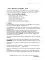
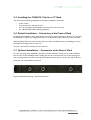
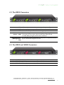
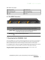
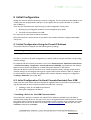
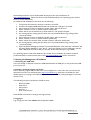
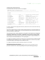
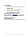
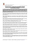
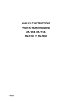
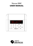
VideoBridge Chassis Unit
CHASSIS-1
Quick Installation Guide
Form number 7660
VIDEOBRIDGE CHASSIS-1 UNIT QUICK INSTALLATION GUIDE VERSION 1.2
© 2008 BRIDGE Technologies Co AS - Mølleparken 4 - N-0459 Oslo, Norway - tel: +47 22 38 51 00 - www.bridgetech.tv
Table of Contents
1
2
3
4
5
About this Quick Installation Guide......................................................................................3
Quick Quick Installation Guide............................................................................................3
Safety..................................................................................................................................3
Verifying the Equipment .....................................................................................................4
The CHASSIS-1 Unit...........................................................................................................4
5.1 Cooling System............................................................................................................4
5.2 CHASSIS-1-AC Power Supply.....................................................................................4
5.3 CHASSIS-1-DC Power Supply....................................................................................5
5.4 Serial Number Location...............................................................................................5
5.5 Installing the CHASSIS-1 Unit in a 19'' Rack ..............................................................6
5.6 Default Installation – Connectors at the Front of Rack.................................................6
5.7 Optional Installation – Connectors at the Rear of Rack................................................6
6 Optional Modules – Connector Descriptions.......................................................................7
6.1 The VB120 Connectors................................................................................................7
6.2 The VB220 Connectors................................................................................................8
6.3 The VB250 and VB260 Connectors.............................................................................8
6.4 The VB280 Connectors................................................................................................9
7 Powering Up the CHASSIS-1 Unit........................................................................................9
8 Initial Configuration............................................................................................................10
8.1 Initial Configuration Using the Preset IP Address.......................................................10
8.2 Initial Configuration Via Serial Console Emulated Over USB.....................................10
9 Verifying Correct Operation of the CHASSIS-1 unit...........................................................13
9.1 Connecting to the Management Interface..................................................................13
9.2 Troubleshooting.........................................................................................................14
10 Obtaining Documentation and Support............................................................................14
11 Returning Equipment.......................................................................................................14
VIDEOBRIDGE CHASSIS-1 UNIT QUICK INSTALLATION GUIDE VERSION 1.2
© 2008 BRIDGE Technologies Co AS - Mølleparken 4 - N-0459 Oslo, Norway - tel: +47 22 38 51 00 - www.bridgetech.tv
2
1 About this Quick Installation Guide
This hardware installation guide describes the CHASSIS1used to house the different Bridgetech
optional modules, the optional modules, rack installation and initial configuration. In this guide the
term CHASSIS1 unit will refer to the 1 rack unit CHASSIS1 with optional modules installed.
2 Quick Quick Installation Guide
1.
2.
3.
4.
5.
6.
7.
Read this installation guide, including safety instructions
Verify the equipment, refer to Chapter 4
Install the unit in a 19'' rack, refer to Chapter 6
Connect the signal cables, refer to Chapter 7
Power up the unit, refer to Chapter 8
Perform initial set-up of IP-addresses, refer to Chapter 9
Verify that the unit operates correctly, refer to Chapter 10
3 Safety
Read the installation instructions before connecting the CHASSIS-1 unit to the power
source. Do not install the CHASSIS-1 unit with power on.
The CHASSIS-1 unit is intended for installation in restricted access areas. A restricted
access area can be accessed only through the use of a special tool, lock and key, or other
means of security.
Blank faceplates and cover panels serve three important functions: they prevent
exposure to hazardous voltages and currents inside the chassis, they provide
electromagnetic interference shielding and they direct the flow of cooling air through
the chassis. Do not operate the CHASSIS-1 unit unless all modules, faceplates, front
covers and rear covers are in place.
Only trained and qualified personnel should be allowed to install, replace or service this
equipment.
This equipment must be installed and maintained by service personnel as defined by
AS/NZS 3260. Incorrectly connecting this equipment to a general-purpose outlet could
be hazardous.
Ultimate disposal of this product should be handled according to all national laws and
regulations.
To prevent the system from overheating, do not operate it in an area that exceeds the
maximum ambient temperature of 45 degrees Celsius.
Do not work on the system or connect or disconnect cables during periods of lightning
activity.
The CHASSIS-1 unit requires short-circuit (overcurrent) protection. Ensure that the
protective device is rated not greater than 120 VAC, 15 A; 240 VAC, 10 A; 60 VDC 20 A.
VIDEOBRIDGE CHASSIS-1 UNIT QUICK INSTALLATION GUIDE VERSION 1.2
© 2008 BRIDGE Technologies Co AS - Mølleparken 4 - N-0459 Oslo, Norway - tel: +47 22 38 51 00 - www.bridgetech.tv
3
4 Verifying the Equipment
When unpacking the CHASSIS-1 unit, the following should be included in the shipment:
•
•
•
•
•
The CHASSIS-1 itself with optional modules installed
A power cable; US, European or UK version depending on region
A 2m USB cable to be used for initial configuration
A user's manual
For CHASSIS-1-DC (-48V DC power supply): a 3-PIN D-sub(15) plug
Inspect the unit for signs of physical damage due to transport. If the unit appears to be damaged it
should not be installed or powered up. In this case the unit should be returned; refer to chapter 12.
5 The CHASSIS-1 Unit
Each CHASSIS-1 unit consists of a 1RU chassis with a maximum of 3 optional modules. The unit can
be equipped with either a 100-240V AC power supply or a -48V DC power supply. The unit is forced
air ventilated, the air flow going from left to right as seen from the connector side of the unit. The
maximum power consumption of the CHASSIS-1 with optional modules is 50W. By default all
connectors and the power plug are located at the front of the unit. However the rack ears of the
CHASSIS-1 may be moved to provide for rear mounting of the unit. The rack ears are designed to
support the weight of the CHASSIS-1 unit.
Figure 1: The CHASSIS-1 Unit – Direction of Air Flow
5.1 Cooling System
The CHASSIS-1 is equipped with three fans that suck in air from the left-hand side of the chassis as
seen in figure 1. The air exits on the right-hand side.
5.2 CHASSIS-1-AC Power Supply
The CHASSIS-1-AC unit is equipped with a 100-240V AC / 50W power supply.
VIDEOBRIDGE CHASSIS-1 UNIT QUICK INSTALLATION GUIDE VERSION 1.2
© 2008 BRIDGE Technologies Co AS - Mølleparken 4 - N-0459 Oslo, Norway - tel: +47 22 38 51 00 - www.bridgetech.tv
4
5.3 CHASSIS-1-DC Power Supply
The CHASSIS-1-DC unit is equipped with a -48V DC / 50W power supply. The power plug is a male
3-PIN D-sub(15) connector. A matching female plug is supplied with the CHASSIS-1-DC unit. This
plug should be soldered to the power cable in accordance with the drawing in figure 3.
Figure 2: The CHASSIS-1- DC Power Plug
------------- A3 - Gnd
------------- A2 - Minus
--------------A1 - Plus
Figure 3: Soldering the Female 3-PIN D-sub(15) Connector to the Power Cable
5.4 Serial Number Location
The serial number of the CHASSIS-1 is located at the rear of the unit. The serial numbers of the
individual optional modules are located on the components side of the modules. All serial numbers
can also be found on the shipping box.
VIDEOBRIDGE CHASSIS-1 UNIT QUICK INSTALLATION GUIDE VERSION 1.2
© 2008 BRIDGE Technologies Co AS - Mølleparken 4 - N-0459 Oslo, Norway - tel: +47 22 38 51 00 - www.bridgetech.tv
5
5.5 Installing the CHASSIS-1 Unit in a 19'' Rack
You will need the following equipment for hardware installation of the unit:
•
•
•
•
4 rack screws
A screw driver for the rack screws
For rear mounting: a size 2 Phillips screwdriver for rack ear screws
For -48 VDC PSU: cable soldering equipment
5.6 Default Installation – Connectors at the Front of Rack
By default the CHASSIS-1 unit is shipped with rack ears for front mounting of the unit. The rack ears
are designed to support the weight of the unit, so no additional support, like a rack shelf, is needed.
When deciding where to locate the unit, make sure there is sufficient space surrounding the unit to
allow efficient cooling, refer to section 5.1.
Use four rack screws to install the unit in the rack.
5.7 Optional Installation – Connectors at the Rear of Rack
For rear mounting of the CHASSIS-1 unit, the rack ears should be moved prior to rack installation.
Unscrew the six size 2 Phillips screws holding the rack ears, and move the six screws covering the
rear mounting holes to the front mounting holes. Remount the rack ears at the rear end of the unit.
Install the unit as described in section 6.1.
Figure 4: Rack Ears Mounting – Side View of Chassis
VIDEOBRIDGE CHASSIS-1 UNIT QUICK INSTALLATION GUIDE VERSION 1.2
© 2008 BRIDGE Technologies Co AS - Mølleparken 4 - N-0459 Oslo, Norway - tel: +47 22 38 51 00 - www.bridgetech.tv
6
6 Optional Modules – Connector Descriptions
The CHASSIS-1 houses one, two or three optional modules. This chapter describes the connectors
present on different modules available.
6.1 The VB120 Connectors
USB: USB serial port emulator for initial set-up of the probe – Type A
ASI INPUT: ASI transport stream input – 75 ohm SMB female
ASI OUTPUT: ASI transport stream output – 75 ohm SMB female
SFP: Alternative SFP input used when connecting to optical networks
T10/100/1000: For monitoring a 10/100/1000 electrical/copper signal – RJ-45.
(Video – eth0) The probe can only monitor either the SFP input signal OR the
T10/100/1000 input signal (selected from software).
MANAGEMENT: For optionally running management of the probe on a separate network
(Management – – RJ-45. This interface supports T10/100.
eth2)
VIDEOBRIDGE CHASSIS-1 UNIT QUICK INSTALLATION GUIDE VERSION 1.2
© 2008 BRIDGE Technologies Co AS - Mølleparken 4 - N-0459 Oslo, Norway - tel: +47 22 38 51 00 - www.bridgetech.tv
7
6.2 The VB220 Connectors
USB: USB serial port emulator for initial set-up of the probe – Type A
ASI INPUT: ASI transport stream input – 75 ohm BNC female
SFP: Alternative SFP input used when connecting to optical networks
T10/100/1000: For monitoring a 10/100/1000 electrical/copper signal – RJ-45.
(Video – eth0) The probe can only monitor either the SFP input signal OR the
T10/100/1000 input signal (selected from software).
MANAGEMENT: For optionally running management of the probe on a separate network (Management – RJ-45. This interface supports T10/100.
eth2)
6.3 The VB250 and VB260 Connectors
RF IN: RF input – 50 ohm F-connector
ASI OUTPUT 1: ASI transport stream output – 75 ohm BNC female
ASI OUTPUT 2: ASI transport stream output – 75 ohm BNC females
GPI: Alarm relay output – 9 PIN D-sub male
VIDEOBRIDGE CHASSIS-1 UNIT QUICK INSTALLATION GUIDE VERSION 1.2
© 2008 BRIDGE Technologies Co AS - Mølleparken 4 - N-0459 Oslo, Norway - tel: +47 22 38 51 00 - www.bridgetech.tv
8
GPI – Alarm relay output
Normal operation
Alarm/Power off
Pins 6-7: Contacts closed
Pins 6-7: No connection
Pins 7-8: No connection
Pins 7-8: Contacts closed
Pin 5: Gnd
Pin 5: Gnd
6.4 The VB280 Connectors
USB: USB serial port emulator for initial set-up of the probe – Type A
SFP: Alternative SFP input used when connecting to optical networks
T10/100/1000: For monitoring a 10/100/1000 electrical/copper signal - RJ-45.
(Video – eth0) The probe can only monitor either the SFP input signal OR the
T10/100/1000 input signal (selected from software).
MANAGEMENT: For optionally running management of the probe on a separate network (Management – RJ-45. This interface supports T10/100.
eth2)
7 Powering Up the CHASSIS-1 Unit
Once the CHASSIS-1 unit is securely mounted and signal cables are connected it can be powered up
by connecting the power cable to a mains source. When the power cable is connected the power
LEDs of the individual optional modules should light up and the chassis fans should operate.
For a CHASSIS-1-DC unit (-48V power supply) the shipped 3-PIN D-sub(15) plug should be soldered
to the power cable prior to power-up. Refer to section 5.3 for a description of this plug.
Note that it will take some time from power-up until the modules can be accessed via the
management interface – typically the start-up time is 45 seconds.
VIDEOBRIDGE CHASSIS-1 UNIT QUICK INSTALLATION GUIDE VERSION 1.2
© 2008 BRIDGE Technologies Co AS - Mølleparken 4 - N-0459 Oslo, Norway - tel: +47 22 38 51 00 - www.bridgetech.tv
9
8 Initial Configuration
Initially the network interface parameters must be configured. This should be done individually for all
modules that are equipped with a USB port. In this chapter the term probe will refer to a module
with a USB port.
There are two alternative ways of performing an initial configuration of the probe:
1. By using the preconfigured IP address of the management port (eth2)
2. Via serial console emulated over USB
For most users the first method will be the easiest.
Note that if there are several probes in the chassis, each module should be configured individually,
one-by-one.
8.1 Initial Configuration Using the Preset IP Address
The probe modules are shipped with the following factory settings:
Management (eth2) IP address: 10.0.20.101
Management (eth2) subnet mask: 255.255.0.0
In order to connect to the eth2 management port the PC used for setup should have corresponding
network settings.
For Windows XP the network parameters are set in the Control Panel - Network Connections
- Local Connections - Properties - Internet Protocol (TCP/IP) view. Select the user defined
address, and set the PC's IP address to 10.0.20.100 and the netmask to 255.255.0.0.
When the IP address of the PC has been set to match the probe's factory settings, the permanent
network settings can be configured through the regular web browser interface. Refer to chapter 9
for a description of how to launch the graphical user interface. Network settings are configured in
the Setup - Ethernet view of the GUI.
8.2 Initial Configuration Via Serial Console Emulated Over USB
If the probe for some reason cannot be reached through Ethernet communication, the initial set-up
may be performed via serial console emulated over USB. This is done by:
1. Installing a driver for the USB communication
2. Setting the management IP address
1. Installing a Driver for the USB Communication
The probe uses a serial port emulator chip called FT232. Windows and MAC users will have to
download and install a driver for this chip. Linux users running distributions with kernel 2.6.x already
have native support. The driver should be downloaded from the end-users login protected area of the
Bridgetech site. To enter the end-users area of the http://www.bridgetech.tv site, use the user name
customer and password xmas4u .
VIDEOBRIDGE CHASSIS-1 UNIT QUICK INSTALLATION GUIDE VERSION 1.2
© 2008 BRIDGE Technologies Co AS - Mølleparken 4 - N-0459 Oslo, Norway - tel: +47 22 38 51 00 - www.bridgetech.tv
10
Alternatively the driver may be downloaded directly from the chip manufacturer at
http://www.ftdichip.com . Select first Drivers, then VCP followed by your operating system (VCP is
short for Virtual COM Port).
For Windows XP installation of the driver do the following:
1.
2.
3.
4.
5.
6.
7.
8.
9.
10.
11.
Temporarily disconnect the internet connection of the PC.
Connect the supplied USB cable between the probe and a USB port on the PC.
When asked to connect to Windows Update, select “No not this time”.
Select "Install from a list or specific location (Advanced)".
Select “Search for the best driver in these locations” and specify a file path.
If a warning appears, stating that the driver has not passed Windows Logo testing, select
“Continue anyway”.
When asked to connect to Windows Update, select “No not this time”.
Select "Install from a list or specific location (Advanced)".
Select "Search for the best driver in these locations" and enter the file path.
If a warning appears, stating that the driver has not passed Windows Logo testing, select
“Continue anyway”.
Open the Device Manager (located in "Control Panel\System" then select the "Hardware" tab
and click "Device Manager"), open "Ports" - the probe appears as a new COM port with the
label "USB Serial Port". Note the port number of this new COM port (e.g. COM3).
For operating systems other than Windows XP a similar driver installation procedure should be
performed. Refer to the documents part of the http://www.ftdichip.com site for instructions.
2. Setting the Management IP-Address
1. Connecting the USB cable
If it is not already connected, connect the USB cable between the USB port on the probe and a USB
port on your PC.
2. Starting a terminal program on the PC
Start a terminal program. Window XP users can use Hyperterm, Linux users can use minicom and
Windows Vista users can download from http://en.poderosa.org . Select the new COM port that
should appear as you plug in the USB cable (linux users should check /var/log/messages to see what
device to use).
The following serial port parameters should be used:
•
•
•
•
•
Baud rate: 9600
Data bits: 8
Parity: None
Stop bits: 1
Flow control: None
Press ENTER a few times to bring up the login prompt.
3. Logging in
Log in using the user name admin and the password elvis.
VIDEOBRIDGE CHASSIS-1 UNIT QUICK INSTALLATION GUIDE VERSION 1.2
© 2008 BRIDGE Technologies Co AS - Mølleparken 4 - N-0459 Oslo, Norway - tel: +47 22 38 51 00 - www.bridgetech.tv
11
4. Setting initial network parameters
A simple text based menu system should now be displayed:
BRIDGETECH terminal management version 3.1.0-26 (Oct 3 2007:16:23:06)
Menu: /ewe/probe/core/setup/ethernet/
==============================================================================
<0> Back
<9> Exit
-----------------------------------------------------------------------------<A> dhcp
- false
Configure eth2 from DHCP server?
<B> netmask
- 255.0.128.0
Netmask of eth2
<C> ipaddress
- 192.168.7.196
IP address of eth2 (management)
<D> management
- true
Run web-server on eth2?
<E> speed
- Autonegotiate
Select line speed for eth2
<F> duplex-mode
- Autonegotiate
Select duplex settings for eth2
<G> data_mask
- 255.255.255.0
Netmask of eth0
<H> data_ipa
- 10.0.30.196
IP address of eth0 (data/video)
<I> data_management
- true
Run web-server on eth0?
<J> data_medium
- Copper
Select copper or fiber for eth0
<K> data_speed
- Autonegotiate
Select line speed for eth0
<L> data_duplex
- Autonegotiate
Select duplex settings for eth0
<M> default_gateway
- 192.168.7.98
Default gateway of probe
<N> reboot
- false
------------------------------------------------------------------------------
To change a setting, press the appropriate character (A-N) then enter the new value and confirm by
pressing <ENTER>.
The probe is equipped with two network interfaces called management (or eth2) and data/video (or
eth0). It is necessary to configure at least one of these interfaces from the terminal and then do the
rest of the setup from a web browser.
The probe supports both in-band management (i.e. using eth0 for both data/video and management)
and separate management (i.e. using eth2 for management). In any case make sure that the subnets
configured for eth0 and eth2 do not overlap – otherwise the probe will not work properly. Note
that if IP-addresses for eth0 and eth2 are configured so that the subnets overlap, the IP-address of
one of the ports will be automatically set to 1.1.1.1 by the probe.
To configure the management interface, edit values for B, C and M, alternatively use DHCP (A). Make
sure Management (E) is enabled (set to true) – otherwise management via web will not be possible.
The speed and duplex mode settings are also available here (F, L).
To configure the data/video interface instead, enter values for G, H, I and M.
5. Saving the parameters and rebooting
When all the listed parameters have been configured, the probe must be rebooted to let the
parameters take effect. This is achieved by pressing the “N” key and confirming by pressing “t”.
VIDEOBRIDGE CHASSIS-1 UNIT QUICK INSTALLATION GUIDE VERSION 1.2
© 2008 BRIDGE Technologies Co AS - Mølleparken 4 - N-0459 Oslo, Norway - tel: +47 22 38 51 00 - www.bridgetech.tv
12
9 Verifying Correct Operation of the CHASSIS-1 unit
A description of the web browser user interface of the equipment is outside the scope of this
installation guide; refer to the relevant user's manual for more information on the GUI. However a
simple operational check can be performed in order to verify correct initial set-up of the
management Ethernet IP address.
9.1 Connecting to the Management Interface
Once the probe network interfaces have been configured as described in chapter 8, all further
configuration takes place through HTTP.
1. Launch a WEB-browser application on the management PC
The following WEB-browsers are supported:
•
•
Internet Explorer 6.0 or higher
Firefox 2.0 or higher
2. Type the IP-address of the probe in the browser URL field and press <ENTER>.
The IP-address of the probe is that of the eth0 or eth2 port (the one used for management) as set in
the initial set-up procedure.
The default management view should be displayed inside the browser. This could look similar to the
screen shot shown below.
VIDEOBRIDGE CHASSIS-1 UNIT QUICK INSTALLATION GUIDE VERSION 1.2
© 2008 BRIDGE Technologies Co AS - Mølleparken 4 - N-0459 Oslo, Norway - tel: +47 22 38 51 00 - www.bridgetech.tv
13
9.2 Troubleshooting
If you are having trouble bringing up the probe web-based management interface verify the following:
•
•
•
•
•
•
•
Verify that the laptop and the probe are configured on the same subnet and that they
have different addresses. The network settings of the probe can be verified through
RS232/USB as described earlier
Make sure that the IP address of the gateway and the network interface are not the same
Verify that the appropriate Ethernet link indicators of the PC and probe are lit
Verify that web browser proxy settings are not interfering
Verify that local firewall settings on the laptop are not interfering
Make sure that the management and data/video subnets do not overlap (even if only one
is physically connected)
Make sure the probe was rebooted to activate the new settings
10 Obtaining Documentation and Support
A user's manual should be included in each VB200 shipment. However the user's manuals are also
available at the end-users log-in area of the www.bridgetech.tv web site. Use the user name customer
and password xmas4u and log-in to access a number of useful technical notes in addition to the
Bridgetech user's manuals.
For technical support contact your Bridgetech reseller.
11 Returning Equipment
If the need should arise to return equipment, contact your Bridgetech reseller for more information
about material return procedures.
VIDEOBRIDGE CHASSIS-1 UNIT QUICK INSTALLATION GUIDE VERSION 1.2
© 2008 BRIDGE Technologies Co AS - Mølleparken 4 - N-0459 Oslo, Norway - tel: +47 22 38 51 00 - www.bridgetech.tv
14