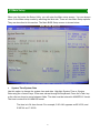
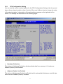
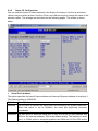
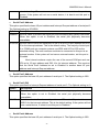
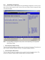
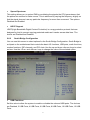
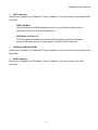
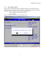
1
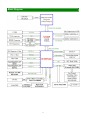
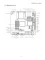
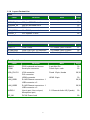
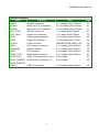
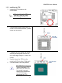
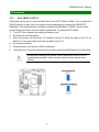
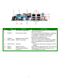
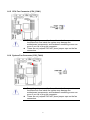
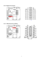
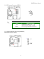
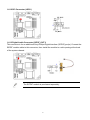
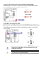
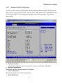
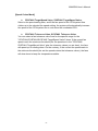
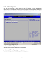
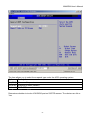
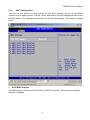
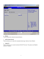
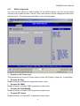
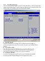
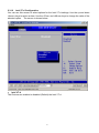
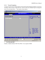
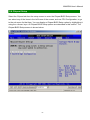
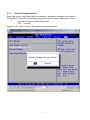
MX45GM
Intel® Socket P GM45 Chipset supports Intel® 45nm Mobile Core™ 2
Extreme,/ Core™ 2 Duo / Celeron processors Mini ITX Motherboard.
User’s Manual
BCM Advanced Research, An Industrial Leader Since 1990 in Industrial Motherboards & Systems
7 Marconi, Irvine, CA 92618 USA | www.bcmcom.com | (PH)949.470.1888 | (FAX)949.470.0971
For Tech Support, please visit www.bcmcom.com/bcm_support_legacyProductSupport.htm
[email protected]
Ver. 1.00
or
contact
Contents
FCC Statement .......................................................................................................................5
Notice......................................................................................................................................5
Copyright Notice .....................................................................................................................5
Trademark Acknowledgement ................................................................................................5
Disclaimer ...............................................................................................................................6
Life Support Policy ..................................................................................................................7
BCM Customer Services.........................................................................................................6
Product Warranty ....................................................................................................................7
Manual Objectives ..................................................................................................................7
Safety Precautions..................................................................................................................8
Document Amendment History ...............................................................................................8
Chapter 1……………………………………………………………………………………………...9
MX45GM Specifications........................................................................................................ 12
Block Diagram………………………………………………………………………………………..12
Before you Proceed ……………………………………………………………………………….. 13
1. Motherboard Overview………………………………………………………………………………...……….. 14
1.1.1
Placement Direction ........................................................................................................................... 14
1.1.2
Screw Holes ....................................................................................................................................... 14
1.1.3
Motherboard Layout ........................................................................................................................... 15
1.1.4
Layout Content List ............................................................................................................................ 16
1.2 Central Processing Unit (CPU)……………………………………………………………...…18
1.2.1
Installing the CPU .............................................................................................................................. 19
1.2.2
Installing the CPU Heatsink and Fan ................................................................................................. 20
1.2.3
Uninstalling the CPU Heatsink and Fan............................................................................................. 21
1.3 System Memory………………………………………………………………………………… 22
1.3.1
SO-DIMM Sockets Location............................................................................................................... 22
1.3.2
Memory Configurations...................................................................................................................... 22
1.3.3
Installing a DDR2 SO-DIMM .............................................................................................................. 23
1.3.4
Removing a DDR2 SO-DIMM ............................................................................................................ 24
1.4 Expansion Slots………………………………………………………………………………….25
1.4.1
Installing an Expansion Card ............................................................................................................. 25
1.4.2
Standard Interrupt Assignments ........................................................................................................ 25
1.4.3
PCI Slots ............................................................................................................................................ 26
1.4.4
PCI Express x1 .................................................................................................................................. 26
1.4.5
Mini PCI Express x 1.......................................................................................................................... 26
2
MX45GM User’s Manual
1.5 Jumpers……………………………………………………………………………………….....27
1.5.1
Clear CMOS (CLRTC1)..................................................................................................................... 27
1.5.2
COM1 RI/+5V/+12V Selection(JCOMPWR3)………………………………….…………………………28
1.5.3
COM2 RI/+5V/+12V Selection(JCOMPWR2)…………………………….………………………….......28
1.6 Connectors.......................................................................................................................29
1.6.1
Rear Panel Connectors…………………………..……………………………………….……………….29
1.6.2
Amplifier Connector (JAMP1)............................................................................................................ 31
1.6.3
Serial Port 2-3 Connector (COM2, COM3) ....................................................................................... 31
1.6.4
Serial Port 4-5 Connector (COM4,COM5) ........................................................................................ 31
1.6.5
CPU Fan Connector (CPU_FAN1).................................................................................................... 32
1.6.6
System Fan Connector (SYS_FAN1)................................................................................................ 32
1.6.7
System Panel Connector (FPIO1)..................................................................................................... 33
1.6.8
Digital I/O Connector ......................................................................................................................... 34
1.6.9
LVDS Connector (JLVDS1)............................................................................................................... 34
1.6.10
LCD Inverter Connector (JBKL1).................................................................................................. 35
1.6.11
Chassis Intrusion Connector (CHASSIS1) ................................................................................... 35
1.6.12
SPI Connector (JSPI1).................................................................................................................. 36
1.6.13
Digital Audio Connector (SPDIF_OUT1) .......................................................................................36
1.6.14
Serial SATA Connector (SATA1, SATA2, SATA3, SATA4) .........................................................37
1.6.15
Serial SATA Power Connector (SATA_POWER1, SATA_POWER2)..........................................38
1.6.16
USB 2.0 Cnnector(USB1,USB2)…..……………..…………………………………………………….38
Chapter 2…………………………………………………………………………………………... 39
2.1 BIOS setup program………………………………………………………….…………………40
2.1.1
Legend Box ........................................................................................................................................40
2.1.2
List Box............................................................................................................................................... 41
2.1.3
Sub-menu........................................................................................................................................... 41
2.2 Main Setup...................................................................................................................... 42
2.3 Advanced BIOS Setup .................................................................................................... 43
2.3.1
CPU Configuration Setting ................................................................................................................. 44
2.3.2
IDE Configuration Setting................................................................................................................... 46
2.3.3
2.3.4
Super I/O Configuration ..................................................................................................................47
Hardware Health Configuration .................................................................................................... 51
2.3.5
ACPI Configuration............................................................................................................................. 54
2.3.6
AHCI Configuration ............................................................................................................................ 57
2.3.7
APM Configuration ............................................................................................................................. 59
3
2.3.8
Intel AMT Configuration ..................................................................................................................... 60
2.3.9
Intel TXT (LT) Configuration .............................................................................................................. 61
2.3.10
Intel VT-d Configuration................................................................................................................. 62
2.3.11
Trusted Computing ........................................................................................................................ 63
2.4 Boot Setting Configuration .............................................................................................. 64
2.4.1
Boot Settings Configuration ............................................................................................................... 64
2.5 Security Setup................................................................................................................. 67
2.5.1
Change Supervisor Password ........................................................................................................... 68
2.5.2
Change User Password ..................................................................................................................... 68
2.6 Chipset Setup ................................................................................................................. 69
2.6.1
North Bridge Configuration ................................................................................................................ 70
2.6.2
South Bridge Configuration................................................................................................................ 72
2.7 Exit Menu ........................................................................................................................ 74
2.7.1
Save Changes and Exit ..................................................................................................................... 75
2.7.2
Discard Changes and Exit ................................................................................................................. 76
2.7.3
Discard Changes................................................................................................................................ 77
2.7.4
Load Setup Default ............................................................................................................................ 78
2.8 Bios Flash ....................................................................................................................... 79
2.8.1
4MB Bios Flash Note ......................................................................................................................... 79
4
MX45GM User’s Manual
FCC Statement
THIS DEVICE SUPPORTS PART 15 FCC RULES. OPERATION IS SUBJECT TO THE
FOLLOWING TWO CONDITIONS:
(1) THIS DEVICE MAY NOT CAUSE HARMFUL INTERFERENCE.
(2) THIS DEVICE MUST ACCEPT ANY INTERFERENCE RECEIVED INCLUDING
INTERFERENCE THAT MAY CAUSE UNDESIRED OPERATION.
THIS EQUIPMENT HAS BEEN TESTED AND FOUND TO COMPLY WITH THE LIMITS FOR A CLASS
"A" DIGITAL DEVICE, PURSUANT TO PART 15 OF THE FCC RULES.
THESE LIMITS ARE DESIGNED TO PROVIDE REASONABLE PROTECTION AGAINST HARMFUL
INTERFERENCE WHEN THE EQUIPMENT IS OPERATED IN A COMMERCIAL ENVIRONMENT. THIS
EQUIPMENT GENERATES, USES, AND CAN RADIATE RADIO FREQUENCY ENERGY AND, IF NOT
INSTATLLED AND USED IN ACCORDANCE WITH THE INSTRUCTION MANUAL, MAY CAUSE
HARMFUL INTERFERENCE TO RADIO COMMUNICATIONS.
OPERATION OF THIS EQUIPMENT IN A RESIDENTIAL AREA IS LIKELY TO CAUSE HARMFUL
INTERFERENCE IN WHICH CASE THE USER WILL BE REQUIRED TO CORRECT THE
INTERFERENCE AT HIS OWN EXPENSE.
Notice
This guide is designed for experienced users to setup the system within the shortest time.
For detailed information, please always refer to the electronic user's manual.
Copyright Notice
Copyright © 2008 BCM Advanced Research, ALL RIGHTS RESERVED.
No part of this document may be reproduced, copied, translated, or transmitted in any form or by any means,
electronic or mechanical, for any purpose, without the prior written permission of the original manufacturer.
Trademark Acknowledgement
Brand and product names are trademarks or registered trademarks of their respective owners.
•
•
•
Intel® and Pentium® are registered trademarks of Intel Corporation.
AMD, Athlon™, Athlon™ XP, Thoroughbred™, and Duron™ are registered trademarks of AMD
Corporation.
NVIDIA, the NVIDIA logo, DualNet, and nForce are registered trademarks or trade-marks of NVIDIA
5
•
•
•
•
•
Corporation in the United States and/or other countries.
PS/2 and OS® are registered trademarks of International Business Machines Corporation.
Windows® 98/2000/NT/XP/Vista are registered trademarks of Microsoft Corporation.
Netware® is a registered trademark of Novell, Inc.
Award® is a registered trademark of Phoenix Technologies Ltd.
AMI® is a registered trademark of American Megatrends Inc.
Disclaimer
BCM Advanced Research reserves the right to make changes, without notice, to any product, including circuits
and/or software described or contained in this manual in order to improve design and/or performance. BCM
Advanced Research assumes no responsibility or liability for the use of the described product(s), conveys no
license or title under any patent, copyright, or masks work rights to these products, and makes no
representations or warranties that these products are free from patent, copyright, or mask
work right infringement, unless otherwise specified. Applications that are described in this manual are for
illustration purposes only. BCM Advanced Research makes no representation or warranty that such application
will be suitable for the specified use without further testing or modification.
Life Support Policy
BCM Advanced Research PRODUCTS ARE NOT FOR USE AS CRITICAL COMPONENTS IN LIFE SUPPORT
DEVICES OR SYSTEMS WITHOUT THE PRIOR WRITTEN APPROVAL OF BCM Advanced Research.
As used herein:
1. Life support devices or systems are devices or systems which, (a) are intended for surgical implant into body,
or (b) support or sustain life and whose failure to perform, when properly used in accordance with instructions
for use provided in the labeling, can be reasonably expected to result in significant injury to the user.
2. A critical component is any component of a life support device or system whose failure to perform can be
reasonably expected to cause the failure of the life support device or system, or to affect its safety or
effectiveness.
BCM Customer Services
Each and every BCM product is built to the most exacting specifications to ensure reliable performance in the
harsh and demanding conditions typical of industrial environments. Whether your new BCM device is destined
for the laboratory or the factory floor, you can be assured that your product will provide the reliability and ease of
operation for which the name BCM has come to be known.
Your satisfaction is our primary concern. Here is a guide to BCM customer services. To ensure you get the full
benefit of our services, please follow the instructions below carefully.
We want you to get the maximum performance from your products. So if you run into technical difficulties, we
are here to help. For the most frequently asked questions, you can easily find answers in your product
documentation. These answers are normally a lot more detailed than the ones we can give over the phone.
So please consult the user’s manual first.
To receive the latest version of the user’s manual; please visit our Web site at www.bcmcom.com.
If you still cannot find the answer, gather all the information or questions that apply to your problem, and with the
product close at hand, call your dealer. Our dealers are well trained and ready to give you the support you need
to get the most from your BCM products. In fact, most problems reported are minor and are able to be easily
solved over the phone.
6
MX45GM User’s Manual
In addition, free technical support is available from BCM engineers every business day. We are always ready to
give advice on application requirements or specific information on the installation and operation of any of our
products. Please do not hesitate to call or e-mail us.
BCM Advanced Research
7 Marconi
Irvine, California, 92618 USA
Phone: +1-949-470-1888
Fax: +1-949-470-0971
Website: www.bcmcom.com
E-mail: [email protected]
Product Warranty
BCM warrants to you, the original purchaser, that each of its products will be free from defects in materials and
workmanship for two years from the date of purchase.
This warranty does not apply to any products which have been repaired or altered by persons other than repair
personnel authorized by BCM, or which have been to misuse, abuse, accident or improper installation. BCM
assumes no liability under the terms of this warranty as a consequence of such events.
Because of BCM high quality-control standards and rigorous testing, most of our customers never need to use
our repair service. If any of BCM products is defective, it will be repaired or replaced at no charge during the
warranty period. For out-of-warranty repairs, you will be billed according to the cost of replacement materials,
service time, and freight. Please consult your dealer for more details. If you think you have a defective product,
follow these steps:
1. Collect all the information about the problem encountered. (For example, CPU type and speed, BCM
products model name, hardware & BIOS revision number, other hardware and software used, etc.) Note
anything abnormal and list any on-screen messages you get when the problem occurs.
2. Call your dealer and describe the problem. Please have your manual, product, and any helpful
information available.
3. If your product is diagnosed as defective, obtain an RMA (return material authorization) number from
your dealer. This allows us to process your good return more quickly.
4. Carefully pack the defective product, a complete Repair and Replacement Order Card and a photocopy
proof of purchase date (such as your sales receipt) in a shippable container. A product returned without
proof of the purchase date is not eligible for warranty service.
Write the RMA number visibly on the outside of the package and ship it prepaid to your dealer.
Manual Objectives
This manual describes in detail the BCM MX45GM Mini-ITX motherboard.
We strongly recommend that you study this manual carefully before attempting to interface with MX45GM or
change the standard configurations. Whilst all the necessary information is available in this manual we would
recommend that unless you are confident, you contact your supplier for guidance.
Please be aware that it is possible to create configurations within the CMOS RAM that make booting impossible.
If this should happen, clear the CMOS settings, (see the description of the Jumper Settings for details).
If you have any suggestions or find any errors concerning this manual and want to inform us of these, please
contact our Customer Service department with the relevant details.
7
Safety Precautions
Always completely disconnect the power cord from your chassis whenever you work
with the hardware. Do not make connections while the power is on. Sensitive electronic
components can be damaged by sudden power surges. Only experienced electronics
personnel should open the PC chassis.
Always ground yourself to remove any static charge before touching the motherboard.
Modern electronic devices are very sensitive to static electric charges. As a safety
precaution, use a grounding wrist strap at all times. Place all electronic components in a
static-dissipative surface or static-shielded bag when they are not in the chassis.
Document Amendment History
Revision
Date
Comment
V1.00
Nov. 02, 2009
First Release
8
MX45GM User’s Manual
Chapter 1
This chapter describes the motherboard features and the new technologies it
supports.
Product Introduction
9
MX45GM Specifications
System
FSB
Supports Intel® socket P Core™ 2 Duo / Intel® Core™ 2 Extreme / Celeron 575
585 mobile CPU with 45nm process technology
667/800/1066 MHz
BIOS
AMI 32Mb SPI BIOS
System Chipset
Intel GM45/ICH9M-E
I/O Chipset
Winbond W83627DHG-A
2 x 200-pin SODIMM socket supports up to 4 GB Dual channel DDR2 667/800
SDRAM
Reset: 1 sec.~255 min. and 1 sec. or 1 min./step
Monitoring CPU temperature, voltage, and cooling fan status. Auto throttling
control when CPU overheats
1 x PCI slot (PCI Rev.2.2 compliant)
CPU
Memory
Watchdog Timer
H/W Status Monitor
Expansion Slots
1 x PCI Express x1 Slot
1 x Compact Flash Type I/II socket
S3
S3 Support
SmartFan Control
Yes
Display
Chipset
Intel Graphics Media Accelerator 4500MHD
Display Memory
Intel DVMT 5.0 supports 1GB video memory
Resolution
2048 x 1536 @ 32 bpp(@ 60Hz)
Dual Display
CRT + LVDS or CRT + DVI-D or CRT + HDMI
LVDS
Dual-channel 24-bit LVDS
DVI
Chrontel CH7318C DVI transmitter up to 165M pixels/second
HDMI
TI SN75DP139 Display Port to TMDS transmitter
Audio
Audio Codec
Realtek ALC888 Audio Codec
5.1+2 CH. with two independent audio stream
Audio Interface
Mic in, Line in, Line out
Audio Amplifier
TPA3005D2 Stereo 6Watt per channel
Ethernet
LAN1
Intel 82567LM Gigabit Ethernet Controller
LAN2
Intel 82574L PCI-E Gigabit Ethernet Controller
Onboard I/O Headers
SATA & SATA Power
4 x Standard SATA Connectors / 2 x SATA Power Connectors
COM
2 x RS-232 Headers (4 ports, 1 with Voltage Selection)
USB
2 x USB 2.0 Headers (4 ports)
SPDIF
1 x SPDIF Header
Front Audio
1 x Front Audio Header
10
MX45GM User’s Manual
Amplifier
1 x Amplifier Header
GPIO
16-bit General Purpose I/O for DI and DO
LVDS
1 x LVDS Connector
Inverter
1 x Inverter Connector
Front Panel
1 x Front Panel Header
Back I/O Panel
Display
1 x DB15 Connector / 1 x DVI-D Connector / 1 x HDMI Connector
LAN / USB / Audio
2 x Stack up RJ45 and USB Connectors / 1 x 3 Jacks Audio connector
RS
1 x COM Port (with voltage selection) / 1 x DIN 6
DC-In
1 x Barrel Type DC In
Power \ Mechanical \ Environmental
Power Requirement
19V ~ 24V
Power Type
19VDC/ 5A and up. Barrel Type (Int. dia 2.5mm – 3mm; Ext. dia 5.5mm)
Operating Temp.
0C – 60C
Operating Humidity
0C – 90C Relative Humidity , Non-Condensing
Form Factor
Mini-ITX
Size (L x W)
6.7” x 6.7”
Weight
0.88” Ibs
Note: Specifications are subject to change without notice.
11
Block Diagram
12
MX45GM User’s Manual
Before you Proceed
Take note of the following precautions before you install motherboard components or change
any motherboard settings.
z
z
z
z
z
Unplug the power cord from the wall socket before touching any
component.
Use a grounded wrist strap or touch a safely grounded object or a
metal object, such as the power supply case, before handling
components to avoid damaging them due to static electricity
Hold components by the edges to avoid touching the ICs on
them.
Whenever you uninstall any component, place it on a grounded
antistatic pad or in the bag that came with the component.
Before you install or remove any component, ensure that the
power supply is off or the power cord is detached from the power
supply. Failure to do so may cause severe damage to the
motherboard, peripherals, and/or components.
13
1. Motherboard Overview
Before you install the motherboard, study the configuration of your chassis to ensure that the
motherboard fits into it. Refer to the chassis documentation before installing the motherboard.
Make sure to unplug the power cord before installing or removing the
motherboard. Failure to do so can cause you physical injury and
damage motherboard components.
1.1.1
Placement Direction
When installing the motherboard, make sure that you place it into the chassis in the correct
orientation. The edge with external ports goes to the rear part of the chassis as indicated in
the image below.
1.1.2 Screw Holes
Place four (4) screws into the holes indicated by circles to secure the motherboard to the
chassis.
Do not over tighten the screws! Doing so can damage the
motherboard.
Place this side towards the rear of
the chassis
14
MX45GM User’s Manual
1.1.3 Motherboard Layout
15
1.1.4 Layout Content List
Slots
Label
Function
Note
(Rear side)
Page
CF1A
Compact Flash connector
N/A
SODIMM_A1
200-pin SODIMM slot 1
22
SODIMM_B1
200-pin SODIMM slot 2
22
PCI1
PCI slot
26
MINI_PCIE1
Mini PCI Express
PCIEX1_1
PCI Express x1 Slot
slot
26
26
Jumpers
Label
Function
Note
Page
CLRTC1
Clear CMOS
3 x 1 header, pitch 2.54mm
27
JCOMPWR3
COM 1 RI/+5V/+12V selection
3 x 2 header, pitch 2.00mm
28
JCOMPWR2
COM 2 RI/+5V/+12V selection
3 x 2 header, pitch 2.00mm
28
Rear Panel Connector
Label
Function
KBMS1
PS/2 keyboard and mouse
COM1
Serial port connector
Note
6-pin Mini-Din
D-sub 9-pin, male
Page
30
29
VGA_DVI-D1
D-sub 15-pin, female
29,30
HDMI 19-pin
30
29,30
HDMI1
LAN_USB1
LAN_USB2
AUDIO1
DC_IN1
VGA connector
DVI connector
HDMI connector
RJ-45 Ethernet connector x 1
USB connector x 2
RJ-45 Ethernet connector x 1
USB connector x 2
Line-in port, Line-out port,
Microphone port,
DC-IN Power Jack
16
29,30
5.1 Channel Audio I/O (3 jacks)
30
29
MX45GM User’s Manual
Internal Connector
Label
Function
JAMP1
Amplifier connector
COM23
Serial port 2 & 3 connector
COM45
Serial port 4 & 5 connector
CPU_FAN1
CPU fan connector
SYS_FAN1
System fan connector
FPIO1
System panel connector
JDIO1
Digital I/O connector
JLVDS1
LVDS connector
JBKL1
LCD Inverter connector
CHASSIS1
Chassis Intrusion
JSPI1
SPI connector
SPDIF_OUT1
Digital Audio connector
SATA1,2,3,4
Serial ATA connectors 1,2,3,4
SATA_POWER1 SATA Power connectors 1,2
SATA_POWER2
USB1,2
USB 2.0 connector
17
Note
4 x 1 header, pitch 2.54mm
10 x 2 header, pitch 2.00mm
10 x 2 header, pitch 2.00mm
3 x 1 wafer, pitch 2.54mm
3 x 1 wafer, pitch 2.54mm
5 x 2 header, pitch 2.54mm
10 x 2 header, pitch 2.00m
HIROSE DF13S-40DP-1.25V
5 x 1 header, pitch 2.00mm
4 x 1 header, pitch 2.54mm
4 x 2 header, pitch 2.54mm
4 x 1 header, pitch 2.54mm
7-pin header
4-pin header
5 x 2 header, pitch 2.54mm
Page
31
31
31
32
32
33
34
34
35
35
36
36
37
38
38
1.2 Central Processing Unit (CPU)
The motherboard comes with a surface mount designed for the Intel® socket P Penryn / Core
2 Duo CPU / Celeron processors.
Please note the marked corner (with gold
triangle) on the CPU. This mark should
match a specific corner on the socket to
ensure correct installation.
z
z
Make sure the power is off before you install the CPU.
After installing the CPU, connect the CPU fan cable to the
CPU_FAN1 connector to ensure system stability.
z
Your boxed Intel® socket P Core 2 Duo CPU with 45nm process
package should come with installation instructions for the CPU or
heatsink.
The product warranty does not cover damage to the socket
contacts resulting from incorrect CPU installation/removal.
z
18
MX45GM User’s Manual
1.2.1 Installing the CPU
1. Locate the CPU socket on the
motherboard.
Before installing the CPU,
make sure that the socket
box is facing towards you.
2.
The processor socket comes with a
screw to secure the processor, please
unlock the screw first.
3.
Position the CPU above the socket
and the gold triangular mark on the
CPU must align with pin 1 of the CPU
socket.
Carefully insert the CPU into the
socket until it fits in place ‘Gold mark’.
Turn the screw to the lock position.
4.
5.
The CPU fits in only one
correct orientation. DO
NOT force the CPU into
the socket to prevent
bending the connectors
on the socket and
damaging the CPU.
19
1.2.2 Installing the CPU Heatsink and Fan
1.
Screw down two fasteners at a time in a
diagonal sequence to secure the heatsink
and fan assembly in place.
2.
Connect the CPU fan cable to the connector on the motherboard labelled
CPU_FAN1.
z
z
Do not forget to connect the fan cables to the fan connectors.
Insufficient air flow inside the system may damage the
motherboard components, and hardware monitoring errors can
occur if you fail to plug this connector.
These are not jumpers! DO NOT place jumper caps on the fan
connectors.
20
MX45GM User’s Manual
1.2.3 Uninstalling the CPU Heatsink and Fan
1.
2.
Disconnect the CPU fan cable from the
connector on the motherboard.
Unscrew each fastener counterclockwise.
3.
Loosen two fasteners at a time in a diagonal
sequence to disengage the heatsink and
fan assembly from the motherboard
4.
Carefully remove the heatsink and fan
assembly from the motherboard.
Refer to the documentation in the boxed or stand-alone CPU fan
package for detailed information on CPU fan installation.
21
1.3 System Memory
1.3.1
SO-DIMM Sockets Location
The motherboard comes with two 200-pin Double Data Rate 2 (DDR2) SO-DIMM sockets.
A DDR2 module has the same physical dimensions as a DDR SO-DIMM but has a 200-pin
footprint compared to the 184-pin DDR DIMM. DDR2 SO-DIMMs are notched differently to
prevent installation on a DDR SO-DIMM socket. The following figure illustrates the location of
the sockets:
1.3.2
Memory Configurations
You can install 512 MB, 1GB and 2GB DDR2 SDRAM SO-DIMMs into the SO-DIMM sockets
using the memory configurations in this section.
z
z
z
z
Installing DDR2 SO-DIMM other than the recommended
configurations may cause memory sizing error or system boot
failure. Use any of the recommended configurations.
Always install SO-DIMMs with the same CAS latency. For
optimum compatibility, it is recommended that you obtain memory
modules from the same vendor.
Due to chipset resource allocation, the system may detect less
than 1 GB system memory when you installed one 1 GB DDR2
memory modules.
Make sure that the memory frequency matches the CPU FSB
(Front Side Bus). Refer to the Memory frequency/CPU FSB
synchronization table.
22
MX45GM User’s Manual
z
Memory frequency/CPU FSB synchronization
CPU FSB
533/800MHz
DDR 2 DIMM Type
DDR2 667
DDR2 800
Memory Frequency
Max clock Freq:
333MHZ; 667Mb/s
Max clock Freq:
400MHZ; 800Mb/s
1.3.3 Installing a DDR2 SO-DIMM
Make sure to unplug the power supply before adding or removing
SO-DIMMs or other system components. Failure to do so may cause
severe damage to both the motherboard and the components.
1.
2.
3.
4.
Locate the SO-DIMM socket on the board.
Hold two edges of the SO-DIMM module carefully, and keep away of touching its
connectors.
Align the notch key on the module with the rib on the slot.
Firmly press the modules into the socket automatically snaps into the mounting notch.
Do not force the SO-DIMM module in with extra force as the SO-DIMM module only fit in
one direction.
23
z
z
A DDR2 SO-DIMM is keyed with a notch so that it fits in only one
direction. DO NOT force a SO-DIMM into a socket to avoid
damaging the SO-DIMM.
The DDR2 SO-DIMM sockets do not support DDR SO-DIMMs.
DO NOT install DDR SO-DIMMs to the DDR2 SO-DIMM socket.
1.3.4
Removing a DDR2 SO-DIMM
1. Press the two ejector tabs on the slot outward simultaneously, and then pull out the
SO-DIMM module.
Support the SO-DIMM lightly with your fingers when pressing the
ejector tabs. The SO-DIMM might get damaged when it flips out with
extra force.
24
MX45GM User’s Manual
1.4 Expansion Slots
In the future, you may need to install expansion cards. The following sub‑sections describe
the slots and the expansion cards that they support.
Make sure to unplug the power cord before adding or removing
expansion cards. Failure to do so may cause you physical injury and
damage motherboard components.
1.4.1 Installing an Expansion Card
1. Before installing the expansion card, read the documentation that came with it and make
the necessary hardware settings for the card.
2. Remove the system unit cover (if your motherboard is already installed in a chassis).
3. Remove the bracket opposite the slot that you intend to use. Keep the screw for later
use.
4. Align the card connector with the slot and press firmly until the card is completely seated
on the slot.
5. Secure the card to the chassis with the screw you removed earlier.
6. Replace the system cover.
1.4.2
Standard Interrupt Assignments
IRQ
0
1
2
3
4
5
6
7
8
9
10
11
12
13
14
15
Priority
1
2
11
12
13
14
15
3
4
5
6
7
8
9
10
Standard Function
System Timer
Keyboard Controller
Redirect to IRQ#9
IRQ holder for PCI streering*
Communications Port (COM1)*
IRQ holder for PCI streering*
Floppy Disk Controller
Printer Port (LPT)*
System CMOS/Real Time Clock
IRQ holder for PCI streeing*
IRQ holder for PCI streeing*
IRQ holder for PCI streeing*
PS/2 Compatible Mouse Port*
Numeric Data Processor
Primary IDE Channel
Secondary IDE Channel
* There IRQs are usually available for ISA or PCI device.
25
1.4.3
PCI Slots
IX45GM has one PCI slots. The PCI slots
support cards such as a LAN card, SCSI card,
USB card, and other cards that comply with PCI
specifications. The figure shows a LAN card
installed on a PCI slot.
1.4.4
PCI Express x1
This motherboard supports PCI Express x1
network cards, SCSI cards and other cards
that comply with the PCI Express
specifications. The figure shows the type of
network card that can be installed on the PCI
Express x1 slot.
1.4.5
Mini PCI Express x 1
This motherboard supports Mini PCI Express
wireless LAN, and TV tuner device.
26
MX45GM User’s Manual
1.5 Jumpers
1.5.1
Clear CMOS (CLRTC1)
This jumper allows you to clear the Real Time Clock (RTC) RAM in CMOS. You can clear the
CMOS memory of date, time, and system setup parameters by erasing the CMOS RTC
RAM data. The onboard button cell battery powers the RAM data in CMOS, which include
system setup information such as system passwords. To erase the RTC RAM:
1. Turn OFF the computer and unplug the power cord.
2. Remove the onboard battery.
3. Move the jumper cap from pins 1-2 (default) to pins 2-3. Keep the cap on pins 2-3 for
about 5~10 seconds, then move the cap back to pins 1-2.
4. Re-install the battery.
5. Plug the power cord and turn ON the computer.
6. Hold down the <Del> key during the boot process and enter BIOS setup to re-enter data.
Except when clearing the CMOS, never remove the cap on CLRTC
jumper default position. Removing the cap will cause system boot
failure!
Normal (Default)
Clear RTC (CLRTC1)
27
1.5.2 COM1 RI/+5V/+12V Selection (JCOMPWR3)
JCOMPWR3
+5V
+
+12V
+
Ring
(Default)
+
1.5.3 COM2 RI/+5V/+12V Selection (JCOMPWR2)
JCOMPWR2
+5V
+
+12V
+
Ring
(Default)
28
+
MX45GM User’s Manual
1.6 Connectors
1.6.1
No
1
2
3
4
Rear Panel Connectors
Label
DC_IN1
COM1
VGA_DVI-D1
LAN_USB1,
LAN_USB2
Function
DC Power In
Serial port connector
DVI port
LAN (RJ-45) connector
Description
19V ~ 24V
D-sub 9-pin, male
Digital Visual Interface connector
This port allows Gigabit connection to a
Local Area Network (LAN) through a
network hub. Refer to the table below for
the LAN port LED indications. The optional
10/100/1000 Mbps LAN controller allows
10/100/1000 Mbps connection to a Local
Area Network (LAN) through a network hub.
ACT / LINK LED
Status
OFF
Orange
Blinking
Description
Status
No link
OFF
Linked
ORANGE
Data activity GREEN
29
SPEED LED
Description
10Mbps connection
100Mbps connection
1Gbps connection
No
5
Label
AUDIO1
Function
Line-In port (Light Blue).
6
AUDIO1
Line-Out port (Lime)
7
8
AUDIO1
USB1, USB2
Microphone port (Pink)
USB 2.0 connector
9
VGA_DVI-D1 VGA port
10
11
HDMI1
KBMS1
HDMI connector
PS/2 Keyboard/Mouse
connector
30
Description
This port connects a tape, CD, DVD player, or
other audio sources.
This port connects a headphone or a speaker.
In 4-channel, 6-channel, and 8-channel
configuration, the function of this port
becomes Front Speaker Out.
This port connects a microphone.
These four 4-pin Universal Serial Bus (USB)
ports are available for connecting USB 2.0
devices.
D-sub15-pin VGA port connects to a VGA
monitor.
High Definition Media Interface 19P connector
The standard PS/2 DIN connector is for a
PS/2 Keyboard or mouse.
MX45GM User’s Manual
1.6.2 Amplifier Connector (JAMP1)
1.6.3 Serial Port 2-3 Connector (COM2,COM3)
1.6.4 Serial Port 4-5 Connector (COM4,COM5)
31
1.6.5 CPU Fan Connector (CPU_FAN1)
z
z
Do not forget to connect the fan cables to the fan connectors.
Insufficient air flow inside the system may damage the
motherboard components, and hardware monitoring errors can
occur if you fail to plug this connector.
These are not jumpers! DO NOT place jumper caps on the fan
connectors.
1.6.6 System Fan Connector (SYS_FAN1)
z
z
Do not forget to connect the fan cables to the fan connectors.
Insufficient air flow inside the system may damage the
motherboard components, and hardware monitoring errors can
occur if you fail to plug this connector.
These are not jumpers! DO NOT place jumper caps on the fan
connectors.
32
MX45GM User’s Manual
1.6.7 System Panel Connector (FPIO1)
This connector supports several chassis-mounted functions.
z
System Power LED (2-pin PWRLED)
This 2-pin connector is for the system power LED. Connect the chassis power LED cable
to this connector. The system power LED lights up when you turn on the system power,
and blinks when the system is in sleep mode.
z
ATX Power Button/Soft-off Button (2-pin PWRSW)
This connector is for the system power button. Pressing the power button turns the
system on or puts the system in sleep or soft-off mode depending on the BIOS settings.
Pressing the power switch for more than four seconds while the system is ON turns the
system OFF.
z
Hard Disk Drive Activity LED (2-pin HDLED)
This 2-pin connector is for the HDD Activity LED. Connect the HDD Activity LED cable to
this connector. The IDE LED lights up or flashes when data is read from or written to the
HDD.
z
Reset Button (2-pin RESET)
This 2-pin connector is for the chassis-mounted reset button for system reboot without
turning off the system power.
33
1.6.8 Digital I/O Connector
1.6.9 LVDS Connector (JLVDS1)
34
MX45GM User’s Manual
1.6.10 LCD Inverter Connector (JBKL1)
z
Signal Description
Signal
Signal Description
VR
Bright adjust. Vadj=0.75V ~ 4.25V
(Recommended: 4.7KΩ, > 1/16W)
ENBKL
LCD backlight ON/OFF control signal
1.6.11 Chassis Intrusion Connector (CHASSIS1)
LCD Inverter Connector (JBKL1)
35
1.6.12 SPI Connector (JSPI1)
1.6.13 Digital Audio Connector (SPDIF_OUT1)
This connector is for an additional Sony/Philips Digital Interface (S/PDIF) port(s). Connect the
S/PDIF module cable to this connector, then install the module to a slot opening at the back
of the system chassis.
The S/PDIF module is purchased separately.
36
MX45GM User’s Manual
1.6.14 Serial SATA Connector (SATA1, SATA2, SATA3, SATA4)
SATA1
SATA2
SATA1
SATA4
SATA3
SATA3 SATA2
SATA4
z
z
Install the Windows® 2000 Service Pack 4 or the Windows® XP
Service Pack1 before using Serial ATA.
When using the connectors in Standard IDE mode, connect the
primary (boot) hard disk drive to the SATA1 connector.
37
1.6.15 Serial SATA Power Connector (SATA_POWER1, SATA_POWER2)
These connectors provide power for SATA devices. Plug SATA Power Cable firmly then
connect SATA power interface on hard drive or optical drive.
SATA Power1
SATA Power2
SATA_POWER2
SATA_POWER1
1.6.16 USB 2.0 Connector (USB1, USB2)
These connectors are for USB 2.0 ports. Connect the USB/GAME module cable to any of
these connectors, then install the module to a slot opening at the back of the system chassis.
These USB connectors comply with USB 2.0 specification that supports up to 480 Mbps
connection speed.
USB1
USB1
USB2
USB2
Never connect a 1394 cable to the USB connectors. Doing so will
damage the motherboard!
The USB module is purchased separately.
38
MX45GM User’s Manual
Chapter 2
This chapter tells how to change the system settings through the BIOS Setup menus.
Detailed descriptions of the BIOS parameters are also provided.
BIOS Setup
39
2.1 BIOS setup program
The main BIOS setup menu is the first screen that you can navigate. Each main BIOS setup
menu option is described in this user’s guide.
The Main BIOS setup menu screen has two main frames. The left frame displays all the
options that can be configured. “Grayed-out” options cannot be configured. Options is blue
can be.
The right frame displays the key legend. Above the key legend is an area reserved for a text
message. When an option is selected in the left frame, it is highlighted in white.
Often a text message will accompany it.
z
The default BIOS settings for this motherboard apply for most
conditions to ensure optimum performance. If the system
becomes unstable after changing any BIOS settings, load the
default settings to ensure system compatibility and stability.
z
z
Select the Load Default Settings item under the Exit Menu.
See section “2.9 Exit Menu.”
The BIOS setup screens shown in this section are for reference
purposes only, and may not exactly match what you see on
your screen.
Visit the Advansus website to download the latest BIOS file for
this motherboard.
2.1.1
Legend Box
The BIOS setup/utility uses a key-based navigation system called hot keys. Most of the BIOS
setup utility hot keys can be used at any time during the setup navigation process.
These keys include <F1>, <F10>, <Enter>, <ESC>, <Arrow> keys, and so on.
The keys in the legend bar allow you to navigate through the various setup menus.
Key(s)
I, J Left/Right
K, L Up/Down
+, - Plus/Minus
Function Description
The Left and Right <Arrow> keys allow you to select an setup screen.
For example: Main screen, Advanced screen, Chipset screen, and so
on.
The Up and Down <Arrow> keys allow you to select an setup item or
sub-screen.
The Plus and Minus <Arrow> keys allow you to change the field value
of a particular setup item.
For example: Date and Time.
40
MX45GM User’s Manual
Tab
F1
The <Tab> key allows you to select setup fields.
The <F1> key allows you to display the General Help screen.
Press the <F1> key to open the General Help screen.
The <F10> key allows you to save any changes you have made and
exit Setup. Press the <F10> key to save your changes.
The <Esc> key allows you to discard any changes you have made
and exit the Setup. Press the <Esc> key to exit the setup without
saving your changes.
The <Enter> key allows you to display or change the setup option
listed for a particular setup item. The <Enter> key can also allow you
to display the setup sub- screens.
F10
ESC
Enter
2.1.2
List Box
This box appears only in the opening screen. The box displays an initial list of configurable
items in the menu you selected.
2.1.3
Sub-menu
Note that a right pointer symbol (X) appears to the left of certain fields. This pointer indicates
that you can display a sub-menu from this field. A sub-menu contains additional options for a
field parameter. To display a sub-menu, move the highlight to the field and press <Enter>.
The sub-menu appears. Use the legend keys to enter values and move from field to field
within a sub-menu as you would within a menu. Use the <Esc> key to return to the main
menu.
Take some time to familiarize yourself with the legend keys and their corresponding functions.
Practice navigating through the various menus and submenus. While moving around through
the Setup program, note that explanations appear in the Item Specific Help window located to
the right of each menu. This window displays the help text for the currently highlighted field.
41
2.2 Main Setup
When you first enter the Setup Utility, you will enter the Main setup screen. You can always
return to the Main setup screen by selecting the Main tab. There are two Main Setup options.
They are described in this section. The Main BIOS Setup screen is shown below.
y System Time/System Date
Use this option to change the system time and date. Highlight System Time or System
Date using the <Arrow> keys. Enter new values through the keyboard. Press the <Tab> key
or the <Arrow> keys to move between fields. The date must be entered in MM/DD/YY format.
The time is entered in HH:MM:SS format.
Note:
The time is in 24-hour format. For example, 5:30 A.M. appears as 05:30:00, and
5:30P.M. as 17:30:00.
42
MX45GM User’s Manual
2.3 Advanced BIOS Setup
Select the Advanced tab from the setup screen to enter the Advanced BIOS Setup screen.
You can select any of the items in the left frame of the screen, such as SuperIO Configuration,
to go to the sub menu for that item. You can display an Advanced BIOS Setup option by
highlighting it using the <Arrow> keys. All Advanced BIOS Setup options are described in this
section. The Advanced BIOS Setup screen is shown below.
The sub menus are described on the following pages.
43
2.3.1
CPU Configuration Setting
You can use this screen to select options for the CPU Configuration Settings. Use the up and
down <Arrow> keys to select an item. Use the <Plus> and <Minus> keys to change the value
of the selected option. A description of the selected item appears on the right side of the
screen. The settings are described on the following pages.
y Hardware Prefetcher
The choices of Hardware Prefetcher which prefetchs data from memory to L2 cache are
Enabled (Default) .and Disabled.
y Adjacent Cache Line Prefetch
The choices of Adjacement Cache Line Prefetch which automatically fetches an extra 64-byte
cache line are Enabled (Default), Disabled.
44
MX45GM User’s Manual
y Max CPUID Value Limit
The choices of Max CPUID Value Limit are Disabled (Default), and Enabled.
y Intel® Virtualization Tech
The choices of Intel® Virtualization Tech are Enabled (Default), Disabled.
y Execute-Disable Bit Capability
The choices of Execute-Disable Bit Capability are Enabled (Default), Disabled.
y Core Multi-Processing
The item is to enable (Default) or disable the Core Multi-processing function.
y Intel® SpeedStep™ tech
The choices of Execute-Disable Bit Capability are Enabled (Default), Disabled.
y Intel® C-State tech
The choices of Execute-Disable Bit Capability are Enabled (Default), Disabled.
y Enhanced C-States
The choices of Execute-Disable Bit Capability are Enabled (Default), Disabled.
45
2.3.2
IDE Configuration Setting
You can use this screen to select options for the IDE Configuration Settings. Use the up and
down <Arrow> keys to select an item. Use the <Plus> and <Minus> keys to change the value
of the selected option. A description of the selected item appears on the right side of the
screen. The settings are described on the following pages.
y SATA#1 Configuration
The choices of SATA configuration are Disabled, Compatible, and Enhanced (Default).
y Configure SATA #1 as
This item allows to configure SATA as IDE (Default), RAID, or AHCI.
y SATA#2 Configuration
The choices of SATA configuration are Disabled and Enhanced (Default).
46
MX45GM User’s Manual
y
Primary/Secondary IDE Master/Slave, Third/Fourth IDE Master, Fifth IDE
Master/Slave
Select one of the hard disk drives to configure it. Press <Enter> to access its the sub
menu. The options on the sub menu are described in the following sections.
y IDE Detect Time Out (Sec)
Set this option to stop the AMIBIOS from searching for IDE devices within the specified
number of seconds. Basically, this allows you to fine-tune the settings to allow for faster boot
times. Adjust this setting until a suitable timing that can detect all IDE disk drives attached is
found.
The default setting is 35.
Option Description
0
This value is the best setting to use if the onboard IDE controllers are set to a
specific IDE disk drive in the AMIBIOS.
5
Set this value to stop the AMIBIOS from searching the IDE bus for IDE disk
drives in five seconds. A large majority of ultra ATA hard disk drives can be
detected well within five seconds.
10
Set this value to stop the AMIBIOS from searching the IDE bus for IDE disk
drives in 10 seconds.
15
Set this value to stop the AMIBIOS from searching the IDE bus for IDE disk
drives in 15 seconds.
20
Set this value to stop the AMIBIOS from searching the IDE bus for IDE disk
drives in 20 seconds.
25
Set this value to stop the AMIBIOS from searching the IDE bus for IDE disk
drives in 25 seconds.
30
Set this value to stop the AMIBIOS from searching the IDE bus for IDE disk
drives in 30 seconds.
35
35 is the default value. It is the recommended setting when all IDE connectors
are set to AUTO in the AMIBIOS setting.
Note: Different IDE disk drives take longer for the BIOS to locate than others do.
47
2.3.3
Super I/O Configuration
You can use this screen to select options for the Super I/O settings. Use the up and down
<Arrow> keys to select an item. Use the <Plus> and <Minus> keys to change the value of the
selected option. The settings are described on the following pages. The screen is shown
below.
y Serial Port1 Address
This option specifies the base I/O port address and Interrupt Request address of serial port 1.
The Optimal setting is 3F8/IRQ4.
Option
Description
Disabled
Set this value to prevent the serial port from accessing any system resources.
When this option is set to Disabled, the serial port physically becomes
unavailable.
3F8/IRQ4 Set this value to allow the serial port to use 3F8 as its I/O port address and
IRQ4 for the interrupt address. This is the default setting. The majority of serial
port 1 or COM1 ports on computer systems use IRQ4 and I/O Port 3F8 as the
48
MX45GM User’s Manual
standard setting. The most common serial device connected to this port is a
mouse. If the system will not use a serial device, it is best to set this port to
Disabled.
y Serial Port2 Address
This option specifies the base I/O port address and Interrupt Request address of serial port 2.
The Optimal setting is 2F8/IRQ3.
Option
Description
Disabled
Set this value to prevent the serial port from accessing any system resources.
When this option is set to Disabled, the serial port physically becomes
unavailable.
2F8/IRQ3 Set this value to allow the serial port to use 2F8 as its I/O port address and IRQ
3 for the interrupt address. This is the default setting. The majority of serial port
2 or COM2 ports on computer systems use IRQ3 and I/O Port 2F8 as the
standard setting. The most common serial device connected to this port is an
external modem. If the system will not use an external modem, set this port to
Disabled.
Note: Most internal modems require the use of the second COM port and use
3F8 as its I/O port address and IRQ 4 for its interrupt address. This requires
that the Serial Port2 Address be set to Disabled or another base I/O port
address and Interrupt Request address.
y Serial Port3 Address
This option specifies the base I/O port address of serial port 3. The Optimal setting is 3E8.
y Serial Port3 IRQ
This option specifies the Interrupt Request address of serial port 3. The Optimal setting is 10.
Option
Description
Disabled
Set this value to prevent the serial port from accessing any system resources.
When this option is set to Disabled, the serial port physically becomes
unavailable.
3E8/IRQ10 Set this value to allow the serial port to use 3E8 as its I/O port address and
IRQ10 for the interrupt address. This is the default setting. If the system will not
use a serial device, it is best to set this port to Disabled.
y Serial Port4 Address
This option specifies the base I/O port address of serial port 4. The Optimal setting is 2E8.
49
y Serial Port4 IRQ
This option specifies the Interrupt Request address of serial port 4. The Optimal setting is 11.
Option
Description
Disabled
Set this value to prevent the serial port from accessing any system resources.
When this option is set to Disabled, the serial port physically becomes
unavailable.
2E8/IRQ11 Set this value to allow the serial port to use 2E8 as its I/O port address and
IRQ11 for the interrupt address. This is the default setting. If the system will not
use a serial device, it is best to set this port to Disabled.
y Serial Port5 Address
This option specifies the base I/O port address of serial port 5. The Optimal setting is 2E0.
y Serial Port5 IRQ
This option specifies the Interrupt Request address of serial port 5. The Optimal setting is 5.
Option
Description
Disabled
Set this value to prevent the serial port from accessing any system resources.
When this option is set to Disabled, the serial port physically becomes
unavailable.
2E0/IRQ5 Set this value to allow the serial port to use 2E0 as its I/O port address and
IRQ5 for the interrupt address. This is the default setting. If the system will not
use a serial device, it is best to set this port to Disabled.
y Watch Dog Timer Control
This option Enabled, Disabled (Default) Watch Dog Timer.
50
MX45GM User’s Manual
2.3.4
Hardware Health Configuration
You can use this screen to select options for the Hardware Health settings. Use the up and
down <Arrow> keys to select an item. Use the <Plus> and <Minus> keys to change the value
of the selected option. The settings are described on the following pages. The screen is
shown below.
y
Chassis Intrusion
This item selects the chassis intrusion. The choices are Disabled or Enabled.
y System Temperature
This shows you the current temperature of system.
y CPU Temperature
This shows you the current CPU temperature.
y
SYS_FAN Speed
51
This shows the current System FAN operating speed.
y CPU_FAN Speed
This shows the current CPU FAN operating speed.
y Vcore/ 3VCC/ +12V/ +5V/ 5VSB/ 3VSB/ VBAT
This shows the voltage of VCORE, 3VCC, +12V, +5V, 5VSB(V), 3VSB(V) and VBAT(V).
y CPUFAN1 Mode Setting, SYSFAN1 Mode Setting
This item enables or disables the Smart Fan feature. Smart Fan is an excellent feature which
will adjust the CPU/system fan speed automatically depending on the current CPU
temperature to prevent your system from overheating.
y Available options are: [Manual Mode], [Thermal Cruise Mode], [Speed Cruise Mode].
[Manual Mode] (Default)
f CPUFAN1 PWM Control, SYSFAN1 PWM Control
This setting allows users to control the fan speed by changing the duty cycle of the
fan PWM (Pulse-Width Modulation) output.
[Thermal Cruise Mode]
f CPUFAN1 TargetTemp Value, SYSFAN1 TargetTemp Value
Select a temperature setting here, and if the temperature of the CPU climbs up to
the selected temperature setting, the system will automatically increase the speed
of the CPU/system fan to cool down the overheated CPU.
f CPUFAN1 Tolerance Value, SYSFAN1 Tolerance Value
You can select a fan tolerance value here for the specific range for the
"CPUFAN1/SYSFAN1 TargetTemp Value" items. If the current temperatures of
the 3 fans reach to the maximum threshold (the temperatures set in the
"CPUFAN1/SYSFAN1 TargetTemp Value" plus the tolerance values you set here),
the fans will speed up for cooling down. On the contrary, if the current
temperatures reach to the minimum threshold (the set temperatures minus the
tolerance values), the fans will slow down to keep the temperatures stable.
f CPUFAN1/SYSFAN1 StartUp Value, CPUFAN1/SYSFAN1 Stop Value
Use these settings to select the startup/stop temperature value for the CPUFAN1
&SYSFAN1.
f CPUFAN1/SYSFAN1 Stop Time Value
Use these settings to select the stop time value for the CPUFAN1 & SYSFAN1.
52
MX45GM User’s Manual
[Speed Cruise Mode]
f CPUFAN1 TargetSpeed Value, SYSFAN1 TargetSpeed Value,
Select a fan speed setting here, and if the fan speed of the CPU/system fans
climbs up to the selected fan speed setting, the system will automatically increase
the speed of the CPU/system fan to cool down the overheated CPU.
f CPUFAN1 Tolerance Value, SYSFAN1 Tolerance Value
You can select a fan tolerance value here for the specific range for the
"CPUFAN1/SYSFAN1/SYSFAN2 TargetSpeed Value" items. If the current fan
speed reach the maximum threshold (the fan speed set in the "CPUFAN1/
SYSFAN1 TargetSpeed Value" plus the tolerance values you set here), the fans
will speed up for cooling down. On the contrary, if the current fan speed reach to
the minimum threshold (the set fan speeds minus the tolerance values), the fans
will slow down to keep the temperatures stable.
53
2.3.5
ACPI Configuration
You can use this screen to select options for the ACPI settings. Use the up and down
<Arrow> keys to select an item. Use the <Plus> and <Minus> keys to change the value of the
selected option. The settings are described on the following pages. The screen is shown
below.
y General ACPI Configuration
This item allows you to set general ACPI Configuration.
y Chipset ACPI Configuration
This item allows you to set South Bridge ACPI Configuration.
54
MX45GM User’s Manual
y Suspend mode
The item allows you to select the suspend type under the ACPI operating system.
Option
Description
S1 (POS)
Power on Suspend
S3 (STR)
Suspend to RAM (Default)
Auto
POS+STR
y Repost Video on S3 Resume
Determines whether to invoke VGA BIOS post on S3/STR resume. The choices are No or
Yes.
55
y
y
USB Device Wakeup From S3
This item allows you to enable or disabled (Default) the USB resume from S3/S4 status.
y
y
y
High Performance Event Timer
This item allows you to enable or disable (Default) the High Performance Event Timer.
y
y
HP
HPET Memory Address
This item allows you to allot the Event Timer Block Registers Base Address to the
memory.
56
MX45GM User’s Manual
2.3.6
AHCI Configuration
You can use this screen to select options for the AHCI settings. Use the up and down
<Arrow> keys to select an item. Use the <Plus> and <Minus> keys to change the value of the
selected option. The settings are described on the following pages. The screen is shown
below.
y AHCI BIOS Support
This BIOS feature controls the AHCI function of SATA controller. The choice are Enabled
(Default) / Disabled
57
y Device
This area shows the detected connected device.
y SATA Port0/1/2/3/4/5
This item allows you to select the connected device type. Options: Auto (Default)
y S.M.A.R.T.
This item allows you to control the device S.M.A.R.T function. The options are Enabled
(Default) / Disabled
58
MX45GM User’s Manual
2.3.7
APM Configuration
You can use this screen to select options for the APM settings. Use the up and down
<Arrow> keys to select an item. Use the <Plus> and <Minus> keys to change the value of the
selected option. The settings are described on the following pages.
y Restore on AC Power Loss
This item allows you to set AC Power Loss to Power Off (Default), Power On, or Last State.
y Resume On Ring
Disable (Default) or Enable RI to generate a wake event.
y Resume On PME#
Disable (Default) or Enable PME to generate a wake event.
y Resume On PCIE WAKE#
Disable (Default) or Enable PCIE to generate a wake event.
y Resume RTC Alarm
Disable (Default) or Enable RTC to generate a wake event.
59
2.3.8
Intel AMT Configuration
You can use this screen to select options for Intel AMT settings. Use the up and down
<Arrow> keys to select an item. Use the <Plus> and <Minus> keys to change the value of the
selected option. The settings are described on the following pages.
z Intel AMT Support
Intel Active Management Technology (AMT) is hardware-based technology for
remotely managing and securing PCs out-of-band. The options are Disabled (Default),
Enabled
z Force IDE/Force SOL
SOL/ IDER (Serial Over LAN/ IDE-Redirection) is a protocol defined for Intel
Active Management Technology that allows redirecting the keyboard/text or
floppy disk/CD transfers from a local host to a remote workstation.
z Unconfigure AMT/ME
To finish the unconfiguration of AMT, set this setting to [Enabled] and the BIOS
will unconfigure all of AMT/ME settings and all the passwords are reset.
60
MX45GM User’s Manual
2.3.9
Intel TXT (LT) Configuration
You can use this screen to select options for the Intel TXT (LT) settings. Use the up and down
<Arrow> keys to select an item. Use the <Plus> and <Minus> keys to change the value of the
selected option. The screen is shown below.
y Intel TXT Initialization
The Choices are enabled or disabled (Default) the Intel TXT initialization.
61
2.3.10 Intel VT-d Configuration
You can use this screen to select options for the Intel VT-d settings. Use the up and down
<Arrow> keys to select an item. Use the <Plus> and <Minus> keys to change the value of the
selected option. The screen is shown below.
y Intel VT-d
The Choices are enabled or disabled (Default) the Intel VT-d.
62
MX45GM User’s Manual
2.3.11 Trusted Computing
You can use this screen to select options for the Intel Trusted Computing settings. Use the up
and down <Arrow> keys to select an item. Use the <Plus> and <Minus> keys to change the
value of the selected option. The screen is shown below.
y TCG/TPM SUPPORT
Enable or disable (Default) TPM TCG (TPM 1.1/1.2) support in BIOS.
63
2.4 Boot Setting Configuration
Select the Boot tab from the setup screen to enter the Boot Setup screen. You can display a
Boot Setup option by highlighting it using the <Arrow> keys. All Boot BIOS Setup options
are described in this section. The Boot BIOS Setup screen is shown below.
2.4.1
Boot Settings Configuration
You can use this screen to select options for the Boot settings. Use the up and down <Arrow>
keys to select an item. Use the <Plus> and <Minus> keys to change the value of the selected
option. The settings are described on the following pages. The screen is shown below.
64
MX45GM User’s Manual
y Quick Boot
The default setting is Enabled.
Option
Description
Disabled Set this value to allow the BIOS to perform all POST tests.
Enabled
Set this value to allow the BIOS to skip certain POST tests to boot faster.
y Quiet Boot
Set this value to allow the boot up screen options to be modified between POST messages or
OEM logo. The default setting is Disabled.
Option
Description
Disabled Set this value to allow the computer system to display the POST messages.
Enabled
Set this value to allow the computer system to display the OEM logo. This is the
default setting.
65
y Bootup Num-Lock
Set this value to allow the Number Lock setting to be modified during boot up. The default
setting is On.
Option Description
Off
This option does not enable the keyboard Number Lock automatically. To use
the 10-keys on the keyboard, press the Number Lock key located on the upper
left-hand corner of the 10-key pad. The Number Lock LED on the keyboard will
light up when the Number Lock is engaged.
On
Set this value to allow the Number Lock on the keyboard to be enabled
automatically when the computer system is boot up. This allows the immediate
use of 10-keys numeric keypad located on the right side of the keyboard. To
confirm this, the Number Lock LED light on the keyboard will be lit. This is the
default setting.
y Wait For “F1” If Error
Set this value to allow the Wait for “F1” Error setting to be modified. The default setting is
Enabled.
Option
Description
Disabled This prevents the to wait on an error for user intervention. This setting should be
used if there is a known reason for a BIOS error to appear. An example would
be a system administrator must remote boot the system. The computer system
does not have a keyboard currently attached. If this setting is set, the system will
continue to boot up in to the operating system. If “F1” is enabled, the system will
wait until the BIOS setup is entered.
Enabled
Set this value to allow the system BIOS to wait for any error. If an error is
detected, pressing <F1> will enter Setup and the BIOS setting can be adjusted
to fix the problem. This normally happens when upgrading the hardware and not
setting the BIOS to recognized it. This is the default setting.
y Hit “DEL” Message Display
Set this value to allow the Hit “DEL” to enter Setup Message Display to be modified. The
default setting is Enabled.
Option
Description
Disabled This prevents to display “Hit Del to Enter Setup” during memory initialization. If
Quiet Boot is enabled, the message will not display.
Enabled
This allows to display “Hit Del to Enter Setup” during memory initialization. This
is the default setting.
66
MX45GM User’s Manual
2.5 Security Setup
Select Security Setup from the Setup main BIOS setup menu. All Security Setup options,
such as password protection and virus protection, are described in this section. To access the
sub menu for the following items, select the item and press <Enter>:
y Change Supervisor Password
The Security Setup screen is shown below. The sub menus are documented on the following
pages.
67
2.5.1
Change Supervisor Password
This item indicates whether a supervisor password has been set. If the password has been
installed, Installed displays. If not, Not Installed displays.
2.5.2
Change User Password
This item indicates whether a user password has been set. If the password has been installed,
Installed displays. If not, Not Installed displays.
68
MX45GM User’s Manual
2.6 Chipset Setup
Select the Chipset tab from the setup screen to enter the Chipset BIOS Setup screen. You
can select any of the items in the left frame of the screen, such as CPU Configuration, to go
to the sub menu for that item. You can display a Chipset BIOS Setup option by highlighting it
using the <Arrow> keys. All Chipset BIOS Setup options are described in this section. The
Chipset BIOS Setup screen is shown below.
69
2.6.1
North Bridge Configuration
You can use this screen to select options for the North Bridge Configuration. Use the up and
down <Arrow> keys to select an item. Use the <Plus> and <Minus> keys to change the value
of the selected option.
Note:
The North Bridge Configuration setup screen varies depending on the supported
North Bridge chipset.
y Boots Graphics Adaptor Priority
This item selects which graphics controller to use as the primary boot device. The options are
IGD, PCI/IGD, PCI/PEG, PEG/IGD, PEG/PCI. The default setting is PEG/PCI.
y Internal Graphics Mode Select
This item selects the amount of system memory used by the internal graphics device. The
choices are Disabled, Enabled 32MB, Enabled 64MB, and Enabled 128MB.
y
Video Function Configuration
70
MX45GM User’s Manual
y
DVMT Mode Select
Use this field to select the memory to allocate for video memory. The choice is
“DVMT”.
-
DVMT/Fixed Memory Size
Specify the size of DVMT/system memory to allocate for video memory. The options
are 128MB, 256MB and Maximum DVMT.
y Boot Display Device
Use the field to select the type of device you want to use as the display(s) of the system.
y Flat Panel Type
This setting allows you to set your preferences for the boot display device.
71
y Spread Spectrum
This setting allows you to reduce EMI by modulating the signals the CPU generates so that
the spikes are reduced to flatter curves. This is achieved by varying the frequency slightly so
that the signal does not use any particular frequency for more than a moment. The options:
Disabled and Enabled.
y HDCP Support
HDCP(High-Bandwidth Digital Content Protection) is a copy protection protocol that was
designed by Intel to prevent copying protected media as it travels across data lines. The
choice are Disabled and Enabled
2.6.2
South Bridge Configuration
You can use this screen to select options for the South Bridge Configuration. South Bridge is
a chipset on the motherboard that controls the basic I/O functions, USB ports, audio functions,
modem functions, IDE channels, and PCI slots. Use the up and down <Arrow> keys to select
an item. Use the <Plus> and <Minus> keys to change the value of the selected option.
y USB Functions
Set this value to allow the system to enable or disable the onboard USB ports. The choices
are Disabled, 2 USB Ports, 4 USB Ports, 6 USB Ports, 8 USB Ports, 10 USB Ports, 12 USB
Ports.
72
MX45GM User’s Manual
y GbE Controller
Options are “Enabled” and “Disabled”. Select “Disabled” if you don’t want to use onboard LAN
controller.
-
GbE LAN Boot
When [Enabled], the BIOS attempts to boot from a LAN boot image before it
attempts to boot from a local storage device.
-
GbE Wake up From S5
This field specifies whether the system will be awakened from the S5 power
saving mode when activity or input signal of onboard LAN is detected.
y OnBoard LAN Boot ROM
Options are “Enabled” and “Disabled”. Select “Disabled” if you don’t want to use onboard LAN
Boot Rom.
y HDA Controller
Options are “Enabled” and “Disabled”. Select “Disabled” if you don’t want to use HDA
controller.
73
2.7 Exit Menu
Select the Exit tab from the setup screen to enter the Exit BIOS Setup screen. You can
display an Exit BIOS Setup option by highlighting it using the <Arrow> keys. All Exit BIOS
Setup options are described in this section. The Exit BIOS Setup screen is shown below.
74
MX45GM User’s Manual
2.7.1
Save Changes and Exit
When you have completed the system configuration changes, select this option to leave
Setup and reboot the computer so the new system configuration parameters can take effect.
Select Exit Saving Changes from the Exit menu and press <Enter>.
Save Configuration Changes and Exit Now?
[Ok] [Cancel]
appears in the window. Select Ok to save changes and exit.
75
2.7.2
Discard Changes and Exit
Select this option to quit Setup without making any permanent changes to the system
configuration. Select Exit Discarding Changes from the Exit menu and press <Enter>.
Discard Changes and Exit Setup Now?
[Ok] [Cancel]
appears in the window. Select Ok to discard changes and exit.
76
MX45GM User’s Manual
2.7.3
Discard Changes
Select Discard Changes from the Exit menu and press <Enter>.
Discard Changes ?
[Ok] [Cancel]
appears in the window. Select Ok to discard changes.
77
2.7.4
Load Setup Default
Automatically sets all Setup options to a complete set of default settings when you Select this
option. The Optimal settings are designed for maximum system performance, but may not
work best for all computer applications. In particular, do not use the Optimal Setup options if
your computer is experiencing system configuration problems. Select Load Setup Defaults
from the Exit menu and press <Enter>. Select Ok to load optimal defaults.
78
MX45GM User’s Manual
2.8 Bios Flash
2.8.1 4MB Bios Flash Note
IMPORTANT: Follow steps 1, 2 below before update Bios for proper Bios flash.
1. 1st memory Dimm Slot (Sodimm_A1) must NOT be occupied.
2. Insert single memory into 2nd Dimm Slot (Sodimm_B1).
Note: MAC address of on-board’s 2nd LAN requires a re-program when flash a 4MB Bios.
Please run flash.bat to flash Bios and update mac address.
Flash Bios:
1. Copy all necessary files* to a DOS bootable device such as USB –Flash drive
2. Boot to dos
3. Run flash.bat to get mac address and update bios, mac address will be stored in mac.bat
4. Reboot to dos
5 Run mac.dat to flash mac address.
*Files includes:
- FPT.exe Programming Tool
- Bios binary file
- Flash.bat
- Fpart.txt
- fptcfg.ini
- dos4gw.exe
- Eeupdate.exe
- RA3.exe
- Basic.txt
79


![[SPT-3000] e](http://vs1.manualzilla.com/store/data/005667089_1-a5f3766b3193f6552f250995926a69c5-150x150.png)