1
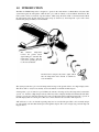
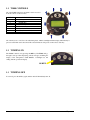
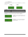
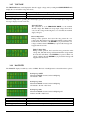
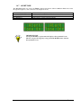
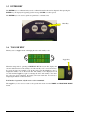
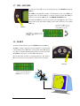
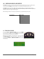
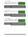
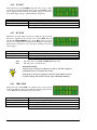
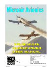
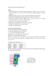
Microair Avionics Pty Ltd
Airport Drive
Bundaberg
Queensland 4670
Australia
Tel:
Fax:
+61 7 41 553048
+61 7 41 553049
e-mail: [email protected]
About This Document
Microair Avionics has developed a series of transponders for use with OEM
applications, and for commercial sale by Microair Avionics. The manual
explains the basic functions and elaborates on the more sophisticated
features, such as altitude display and alerts.
Revision 2.9 of this manual is to be supplied and used in conjunction with
T2000SFL-01 (6) transponders with software version 1.6.4.
Microair reserves the right to amend this manual as required, to reflect any
enhancements or upgrades to the T2000 Transponder series.
© Microair Avionics Pty Ltd
Statement:
The T2000SFL owner accepts all responsibility for obtaining the proper licensing before using the transponder. The coverage you can
expect from the T2000SFL is limited to “line of sight”. Low altitude or aircraft antenna shielding by the aircraft itself may result in a
reduced range. Range can be improved by climbing to a higher altitude. It may be possible to minimize antenna shielding by locating the
antenna where dead spots are only noticed during abnormal flight attitudes.
The T2000SFL should be turned off before starting or shutting down aircraft engine(s).
MICROAIR DOCUMENTS
Microair T2000 Users Manual
Microair T2000 Installation Manual
Microair T2000 Flight Manual Supplement
Microair T2000 Service Manual
T2000-DOC-001
T2000-DOC-002
T2000-DOC-003
T2000-DOC-004
DOCUMENT REVISION STATUS – T2000-DOC-001
Revision
1.0
2.2
2.3
2.4
2.5
2.6
2.7
2.8
2.9
T2000 user manual V29
Date
11/02/01
11/07/01
22/08/01
05/10/01
12/10/01
07/11/01
01/06/02
22/11/03
08/04/05
Change
Initial Draft
Voltage Monitoring
Standby function added
Hi / Lo alerts added
Mode and Program Mode menu functions amended
Deleted SF references
Assigned Alt & Buffer Alt input amended, Name/Reg relocated to end of Program Mode
ID and VFR key instructions amended
Amended for function changes incorporated into software revision 1.6.4
Page 2 of 28
8th April 2005
TABLE OF CONTENTS
1.0
INTRODUCTION ......................................................................................... 4
1.1
1.2
1.3
1.4
1.5
T2000 CONTROLS ............................................................................................................ 5
TURNING ON.................................................................................................................... 5
TURNING OFF .................................................................................................................. 5
DISPLAY LAYOUT........................................................................................................... 6
SPECIAL CODES .............................................................................................................. 6
2.0
DISPLAY FUNCTION.................................................................................. 7
3.0
CONTROL FUNCTIONS ............................................................................. 8
3.1
3.2
3.3
3.4
SELECTMODE KNOB ...................................................................................................... 8
CODE SELECT KNOB ...................................................................................................... 9
ON KEY............................................................................................................................. 9
MODE KEY ..................................................................................................................... 10
3.4.1
3.4.2
3.4.3
3.4.4
3.4.5
3.4.6
3.4.7
QNH OR BARO (BAROMETRIC PRESSURE) ......................................................................................................11
ASSIGNED (ALTITUDE)...........................................................................................................................................12
BUFFER ALT...............................................................................................................................................................13
ALTITUDE (UNITS) ...................................................................................................................................................14
VOLTAGE ....................................................................................................................................................................15
BACKLITS ...................................................................................................................................................................15
ALERT TONE ..............................................................................................................................................................16
3.5
3.6
3.7
3.8
ENTER KEY .................................................................................................................... 17
TOGGLE KEY ................................................................................................................. 17
VFR – HOT KEY.............................................................................................................. 18
ID KEY ............................................................................................................................ 18
4.0
INITIALISATION AND SETUP................................................................ 19
4.1
PROGRAM MODE .......................................................................................................... 19
4.1.1
4.1.2
4.1.3
4.1.4
4.1.5
4.1.6
4.1.7
4.1.8
4.1.9
VOLT MON..................................................................................................................................................................20
A/C VOLT ....................................................................................................................................................................20
O/V SET ........................................................................................................................................................................20
U/V SET ........................................................................................................................................................................21
E/C POW.......................................................................................................................................................................21
VFR CODE ...................................................................................................................................................................21
BARO ............................................................................................................................................................................22
REM STBY...................................................................................................................................................................22
EXIT PROGRAM ........................................................................................................................................................22
5.0
FREQUENTLY ASKED QUESTIONS: .................................................... 23
6.0
LIMITED WARRANTY............................................................................. 27
T2000 user manual V29
Page 3 of 28
8th April 2005
1.0 INTRODUCTION
The Microair T2000 Transponder is designed to operate in the environment of a Radar Beacon System. This
system interrogates the transponder, which in turn replies with an identity code and altitude information. The
radar system consists of a network of ground stations, which sweep the horizon like a conventional radar. When
the transponder in the aircraft detects the radar sweep (is illuminated), the transponder replies with a burst
transmission giving its identity code and altitude.
The
aircraft’s
transponder
receives the ground station
signal asking it to transmit. The
transponder “replies” with the
code, and if operating in mode
C, the encoder altitude.
Ground stations sweep the sky with a signal, which
asks the transponder in the aircraft to transmit its
code and altitude.
The system presents the replies from all transponders in range of the ground stations on a single display screen.
This allows ATC to easily locate, identify, and see the altitude of all traffic in their airspace.
A transponder’s reply is termed a squawk. Hence the current code being used by the transponder is termed the
squawk code. At times of high airspace activity, ATC may wish to uniquely identify an individual aircraft with a
request to squawk ident. The pilot uses the ident control on the transponder to make the transponder’s squawk on
the ATC display flash for a short period. The ident control should not be used unless ATC request it.
ATC will issue a code to an aircraft requesting entry into its controlled airspace. This code is normally unique
for each aircraft, each time that aircraft passes through the airspace. The code is 4 digits long, and each digit can
range from 0-7.
T2000 user manual V29
Page 4 of 28
8th April 2005
1.1 T2000 CONTROLS
All of the T2000’s functions and features can be accessed
from the controls on the front face.
CONTROL
1
2
3
4
5
6
7
8
DESCRIPTION
ON Key
MODE Key
ENTER Key
IDENT Key
TOGGLE Key
CODE SELECT Knob
SELECTMODE Knob
VFR Key
All of the keys are covered in a soft rubberized plastic, which is backlight with the display. When the key is
pressed a small click can be discerned. The selected function will operate on the release of the key.
1.2 TURNING ON
The T2000 is turned on by pressing the ON key. The T2000 will go
through a start up routine displaying self test messages, including the
display of the transponder’s serial number, a backlight test, and
ending with the operational display.
ON KEY
1.3 TURNING OFF
To turn off, press the ON key again, and the unit will immediately turn off.
T2000 user manual V29
Page 5 of 28
8th April 2005
1.4 DISPLAY LAYOUT
The Microair T2000 SFL is a 57mm diameter face version
to fit the standard 2 ¼ inch instrument hole.
The mounting is by 4 x M4 machine screws, located
through the panel and screwed into threaded holes in each
corner of the transponder’s front face.
Clean only with a dry cloth, and do not allow the display
face to become wet.
The mode of operation is set using the SELECT MODE
knob located at the lower left, and the standby code
(displayed on the lower line of the display) can be edited
with the CODE SELECT knob, located at the lower right.
T2000SFL Front Face
1.5 Special Codes
There are several special codes, which are used to identify General Aviation aircraft, and some special situations
which aircraft could encounter. Misuse of these codes may result in legal charges against the user.
IMPORTANT NOTE
ALWAYS check the standby code, BEFORE transferring it to the ACTIVE
position.
0000
1200
2000
3000
7000
7500
7600
7700
7777
General Purpose code subject to regional agreement
Civil VFR Flights OCTA not participating in Radar
Information Service (RIS). General Aviation Code (US and
other countries)
Civil IFR Fights OCTA not participating in RIS
Civil Flights in Controlled airspace
VFR General Aviation Code (Europe)
Unlawful Interference Code
Radio Communications Failure
Emergency Code
Military Intercept Code (NEVER USE)
Code 2100 is a test code that can be used by qualified personal to test the transponder to ATC.
The user should check the Civil Aviation Rules/Regulations to determine the VFR General Aviation transponder
code for their country.
T2000 user manual V29
Page 6 of 28
8th April 2005
2.0 DISPLAY FUNCTION
The T2000SFL is a dual line display of 8 characters each, with the active code on the top line, and the standby
code on the bottom. With the SELECTMODE knob set to either the ON or ALT positions, the active code is
displayed on the top line, and the standby code is displayed on the bottom line.
In the top left corner the operational mode character (X, A, or C character) is displayed. Next to it is the ADS-B
annunciator (* character) which flashes with every ADS-B squitter transmitted. At the top right is the Mode A/C
annunciator (R character) which also flashes with every transponder reply transmitted. If the ID key is pressed
to activate the ident function, the R character is replaced with an I character while the ident function is
operating.
* character (flashing)
ADSB annunciater
X - STANDBY
Neither code or altitude are sent
Active Code
The transmitted ID code
A - MODE 3A
Transmit ON – Only ID code sent
I character
Squawk Ident operation
R character (flashing)
Mode A/C annunciater
C - MODE C
Transmit ON – ID Code and altitude sent
Standby Code
Never Transmitted
With the SELECT MODE knob in the ALT DISPLAY position, the active code is displayed on the top line,
and the encoder altitude is displayed on the bottom line. If the latitude units are set to feet the altitude is
followed by the F character. If the altitude units are in metres, the altitude is followed by the M character. If no
QNH or BARO value has been entered (default 1013mB or 29.92HG), the raw encoder output is displayed as
“pressure altitude”, and the characters PA appear at the lower left. If a QNH / BARO value has been set, the Q
character appears at the lower left.
PA Pressure Altitude as sent
from the altitude encoder.
F Feet
Altitude units are in Feet
Q Altitude is adjusted for
QNH or barometric pressure
from the mode menu
Displayed Altitude
Altitude generated by Encoder, and may be
adjusted for barometric pressure (QNH)
If the Encoder is not powered or not fitted, the message NO ALT will appear on the display.
The T2000 will transmit the encoder altitude (pressure altitude) only, in accordance with normal mode C
operation. The adjusted QNH / Baro altitude is never transmitted.
T2000 user manual V29
Page 7 of 28
8th April 2005
3.0 CONTROL FUNCTIONS
This section describes the transponder control keys and their functions. Many of the control keys have more
than one function, and some keys access multi-option menus, which can be scrolled.
3.1 SELECT MODE KNOB
The SELECT MODE knob allows the user to switch the transponder
between the 4 operating modes.
Select Mode Knob
STANDBY
In standby the transponder is powered up, but will not transmit.
ON
On the active display line the letter X appears on the left hand side.
Will reply to Mode A interrogations. Mode C blind encoder is normally powered up in this mode, but
can be powered down if encoder power option is set OFF (refer E/C POW in Initialisation and Setup
section).
ALT
On the active display line the letter A appears on the left hand side.
Will reply to Mode A and C interrogations, with the mode C encoder information. In the absence of a
valid encoder input, only the C framing pulse will be sent.
ALT DISPLAY
On the active display line the letter C appears on the left hand side.
The standby code is replaced with the encoder altitude. If the pressure has been set via the QNH /
Baro option of MODE MENU, the displayed altitude will be adjusted for barometric air pressure.
Altitude will be displayed in units set in ALTITUDE option of MODE MENU.
The DISPLAY ALT only displays altitude if a valid encoder input is being received. When
climbing above the transition level/layer, the user must reset the transponder at the same time as the
aircraft’s altimeter to 1013mb or 29.92HG.
On the active display line the letter C appears on the left hand side.
Examples of pressure adjusted encoder altitude
Examples of encoder altitude
Examples of encoder altitude
T2000 user manual V29
Examples of pressure adjusted encoder altitude
Page 8 of 28
8th April 2005
3.2 CODE SELECT KNOB
The CODE SELECT knob can be rotated clockwise to scroll
upwards, and counter-clockwise to scroll downwards. Each digit of
the code is adjusted separately. The adjust function starts with the left
hand digit, and is moved across to the next digit by pushing the
CODE SELECT knob inwards. After 10 seconds of inactivity the
cursor will revert to the left hand digit.
When operating in the Display Alt mode, the actual Gillham 4 digit
altitude code can be displayed by pressing and holding the code select
knob in.
Code Select Knob
3.3 ON KEY
The T2000SFL is turned on by pressing the ON key.
The T2000SFL will first
display the product name,
then…
the serial number of the
unit, as a security
protection.
On Key
The T2000 then performs a quick self test before moving on to the operational screen, in whatever mode the
select mode knob is set to.
T2000 user manual V29
Page 9 of 28
8th April 2005
3.4 MODE KEY
The MODE key can be used to access two separate menus:
Mode Key
• If the transponder is turned on, by holding down the MODE key, and pressing the ON key, the T2000 will
start in PROGRAM MODE. The MODE key must be held down, until the start-up self-test messages have
been displayed.
• If the transponder is ON and in normal operation, press the MODE key to access the MODE MENU. The
first item of the MODE MENU is displayed. Step through the MODE MENU by pressing the MODE key.
After the last menu item the T2000 returns to the operational display currently in use.
The MODE MENU is designed to allow the operator fast easy access to functions and parameters, which may
need to be adjusted in flight.
MODE MENU
T2000 user manual V29
QNH or Baro
Assigned
Buffer Alt
Altitude
Voltage
Backlits
Alert Tone
USE MODE KEY TO STEP THROUGH
MENU OPTIONS
OR
USE THE Toggle KEY TO RETURN TO
THE OPERATIONAL DISPLAY
Page 10 of 28
8th April 2005
3.4.1 QNH or BARO (Barometric Pressure)
The altitude encoder outputs a pressure altitude fixed at an above mean sea level (AMSL) pressure of 1013mb
or 29.92Hg. The aircraft’s altimeter however is normally adjusted for actual surface pressure before take off.
This means the encoder altitude may not be the same as the altimeter reading.
The QNH / Baro can be entered here to allow the T2000 to compensate the displayed altitude for surface
pressure, and hence read the same as the aircraft’s altimeter. The default QNH is 1013mb or Baro is 29.92HG.
If the QNH / Baro is set to 1013mb or 29.92HG, the altitude displayed will default to the unadjusted pressure
altitude direct from the encoder. If the QNH / Baro is set to a discrete value (normally provided by ATC), the
encoder pressure altitude displayed will be adjusted for that QNH / Baro value.
The barometric units are set in the BARO option of the PROGRAM MODE. When MB is selected the QNH
screen is displayed, and when HG is selected the Baro screen is displayed.
Press MODE key (once)
Rotate CODE SELECT knob
Press ENTER key
Press toggle key
To select QNH / Baro option
Scroll lower line to desired pressure.
To set default value. The default is 1013(mb) or 29.92(HG
Display returns to current operational display
IMPORTANT NOTE
The T2000 will only transmit the encoder pressure altitude. The
adjusted QNH / Baro altitude is NEVER transmitted, even when it is
selected for display.
T2000 user manual V29
Page 11 of 28
8th April 2005
3.4.2 ASSIGNED (altitude)
The user can input an assigned altitude given by ATC. When used with the altitude buffer value, an audio alert
and display indicator advises when the aircraft has climbed or descended, from the assigned altitude.
When the Altitude option of the mode menu is set to Feet, the
Assigned altitude is adjusted in feet.
When the Altitude option of the mode menu is set to Meters,
the Assigned altitude is adjusted in Meters.
Press MODE key (2 times)
Press CODE SELECT knob
Rotate CODE SELECT knob
Press ENTER key
Press toggle key
To select Assigned option
Increment displayed value in units of 500 feet / 100m / FL50
Increment displayed value in units of 100 feet / 10m / FL10
To set default value. The default is 0.
To save and display returns to current operational display
When entering an altitude…
Press the CODE SELECT knob to increase the height value in units
of 500FT / 100M / FL50.
Rotate the CODE SELECT knob to increase or decrease the height
value in units of 100FT / 10M / FL10.
Press the ENTER key to return the ASSIGNED ALTITUDE to the default value of 0,
Press the Toggle key to save the height value, and return to the operational display.
or
If Assigned is set to 0, the altitude alert function is disabled. The assigned altitude function is only active when
the SELECTMODE knob is set to DISP ALT.
T2000 user manual V29
Page 12 of 28
8th April 2005
3.4.3 BUFFER ALT
The user can input a buffer altitude, above and below the assigned
altitude, to define a height band in which to fly. When the aircraft
exceeds the upper or lower limit, an indicator alert message will be
displayed. The alert message advises the pilot of how far, above or
below the assigned altitude the aircraft is. If the Alert Tone function
is ON, an audio tone is heard as well.
If the ALTITUDE option in the PROGRAM MODE is set to FEET the Buffer Alt increments are in feet. If
ALTITUDE is set to METRES, the Buffer Alt increments are in meters.
Press MODE key (3 times)
Press CODE SELECT knob
Rotate CODE SELECT knob
Press ENTER key
Press Toggle key
To select Buffer Alt option
Increment displayed value in units of 500 feet / 100m
Increment displayed value in units of 100 feet / 10m
Display returns to current operational display (No default value)
Display returns to current operational display
ALTITUDE BUFFER
ALTITUDE BUFFER
With the Assigned altitude set at 3500 feet, and the
Buffer Alt set at 200 feet, the display alerts will
occur over 3700 feet and under 3300 feet.
ASSIGNED ALTITUDE
No alert will be displayed while the aircraft remains
inside the 3700-3300 buffer.
If the aircraft climbs or descends outside the altitude buffer limits, a Hi / Lo warning is displayed on the lower
line.
T2000 advises the pilot that the aircraft is 500 feet above
the Assigned altitude. If the Alert Tone function is set on,
an audio warning tone is heard.
T2000 advises the pilot that the aircraft is 500 feet below
the Assigned altitude. If the Alert Tone function is set on,
an audio warning tone is heard.
T2000 user manual V29
Page 13 of 28
8th April 2005
3.4.4 ALTITUDE (units)
The altitude data can be displayed as feet, flight level, or meters. Once the Altitude units are set, all altitude data
is displayed in these units.
The options are:
F = FEET
M = METERS
Press MODE key (4 times)
Rotate CODE SELECT knob
Press ENTER key
Press Toggle key
e.g. 15000F
e.g. 5000 M
To select Altitude option
Scroll to select desired units. Options are Feet or Meters
No operation. (No default value)
Display returns to current operational display
In both examples below the PA characters displayed at the lower left indicate “pressure altitude”, where the
QNH / BARO value has been left at the default value (1013mB or 29.92HG) in the MODE menu.
5350 FEET. Units in feet are indicated by the F character at the
right hand end of the lower display line. All altitude data will be
displayed in feet.
1250 METERS. Units in meters are indicated by the M character
at the right hand end of the lower display line. All altitude data
will be displayed in meters.
T2000 user manual V29
Page 14 of 28
8th April 2005
3.4.5 VOLTAGE
The VOLTAGE function will display the aircraft’s supply voltage, and by rotating the CODE SELECT knob,
display the over and under voltage alert levels.
Press MODE key
Press ENTER key
Press Toggle key
(5 times)
To select Voltage option. The supply voltage is display on the lower line
No operation. No default value.
Display returns to current operational display
When the transponder is operating in normal display operation mode, the over and under input voltage alert
message is displayed on the lower line.
Aircraft Voltage
This parameter is set in PROGRAM MODE, as the nominal
aircraft voltage. The T2000 can accept input voltages from 10-33
volts, but the voltage monitoring has to be told what the nominal
supply voltage is.
Over Voltage Alert
During normal operation, the bottom line may present the over
voltage alert. The alert message will remain until the voltage returns
below the O/V alert limit, or the ENTER key is pressed. If the over
voltage continues after the ENTER key is pressed the message will
reappear after 10 seconds.
Under Voltage Alert
During normal operation, the bottom line may present the under
voltage alert. The alert message will remain until the voltage returns
above the U/V alert limit, or the ENTER key is pressed. If the over
voltage continues after the ENTER key is pressed the message will
reappear after 10 seconds.
3.4.6 BACKLITS
The T2000SFL display is backlit by a series of LEDS. The level of backlight can be selected from three options:
Backlighting is OFF
When the T2000SFL is turned on the backlighting
will default to OFF.
Backlighting is LO
When the T2000SFL is turned on the backlighting
will default to the LO or 50% level.
Backlighting is HI
When the T2000SFL is turned on the backlighting will
default to the HI or 100% level.
Press MODE key (6 times)
Rotate CODE SELECT knob
Rotate ENTER key
Press Toggle key
T2000 user manual V29
To select Backlits option. The current setting is displayed.
To select from OFF / LO / HI
To save backlist level.
Display returns to current operational display
Page 15 of 28
8th April 2005
3.4.7 ALERT TONE
The Alert Tone function is used by the T2000’s altitude alert function. When set ON, the Alert can be heard
through the headphones, when connected to the headphone circuit.
Press MODE key (7 times)
Rotate CODE SELECT knob
Press ENTER key
Press Toggle key
To select Alert Tone option
Scroll lower line to select ON or OFF. The default is ON
No operation. No default value.
Display returns to current operational display
IMPORTANT NOTE
Pressing the MODE key again returns the display to the operational screen.
The user can press the toggle key at any point in the MODE menu to return to
the operational screen.
T2000 user manual V29
Page 16 of 28
8th April 2005
3.5 ENTER KEY
The ENTER key is a confirmation key used to confirm information the user has inputted. After pressing the
ENTER key, the display will typically give the message SAVED, for a short period.
The ENTER key is also used to quick-set a parameter to a default value.
Enter Key
3.6 TOGGLE KEY
This key acts as a toggle switch, exchanging the active and standby codes.
Toggle Key
When the transponder is operating in DISPLAY ALT the bottom line displays the
encoder altitude instead of the standby code. The standby code is stored in memory.
To toggle the active and standby codes in this mode, push the toggle key once to
display the standby code on the bottom line. The standby code is displayed for 10
seconds. Push the toggle key again to exchange the active and standby codes. Once
the codes have been exchanged, the display will revert back after 10 seconds, to
displaying the altitude on the bottom line.
In all modes of operation, only the active code is transmitted.
The toggle key is also used to return to the operational screen from the MODE and PROGRAM MODE
menus.
T2000 user manual V29
Page 17 of 28
8th April 2005
3.7 VFR – HOT KEY
To bring the stored VFR code to the standby line press the ENTER key then the
VFR key.
The VFR key will default the standby code immediately to the stored VFR code.
Typically this code will be 1200 for a General Aviation aircraft. The VFR key
calls the value set in the VFR option of the PROGRAM MODE menu.
To transfer the VFR code to the active position, press the toggle key. If no code is
entered, after 10 seconds idle the standby position will revert back to the original
VFR code.
To make the VFR code the
active code, press the toggle key
to bring VFR to the top line
VFR Key
Press VFR key to bring the stored
VFR code to the standby line. In this
case VFR = 1200
3.8 ID KEY
To initiate the Ident function press the ENTER key then the ID key.
The ID key ( Ident ) when pressed, adds additional code information
to the transmission for ATC. The code will flash on the ATC display
as a means of uniquely identifying the aircraft’s code from any other.
The T2000 has the option of a remote ID switch (pin 16).
The external switch should be a momentary-ON type. The switch or
ID key only need to be pressed briefly to activate the ident function.
Ident Key
I character replaces the R, while the
IDENT function is in operation
T2000 user manual V29
Page 18 of 28
8th April 2005
4.0 INITIALISATION AND SETUP
The T2000 will operate as a conventional transponder when first installed and powered up. You will be able to
turn the transponder ON/OFF, adjust the standby code, and transfer the standby and active codes.
The T2000 has many other features, which can be programmed. Microair recommends that the full setup
procedure be carried out prior to first flight. This section provides detailed procedures on the various parameters
and functions that can be setup from the front panel.
The following procedures provide step by step instructions to program the transponder options.
Program Mode
VOLT MON
A/C VOLT
O/V Set
U/V Set
E/C POW
VFR CODE
BARO
REM STBY
EXIT PROGRAM
4.1 PROGRAM MODE
To start the T2000 in PROGRAM MODE, hold down the MODE
key, and then press the ON key. Keep the MODE key held down until
the start up self test messsages have been displayed.
Each item can be adjusted to the desired value or option by scrolling
the CODE ADJUST knob. The selected value or option can be saved
by pressing the ENTER key. PROGRAM MODE then moves to the
next menu item.
T2000 user manual V29
Page 19 of 28
8th April 2005
4.1.1 VOLT MON
The T2000 can monitor aircraft voltage, and alert the pilot to the
aircraft electrical system over or under voltage conditions. This is the
aircraft supply voltage not just the transponder voltage, and is very
useful for troubleshooting aircraft electrical problems.
Press ENTER key
Rotate CODE SELECT knob
Press the ENTER key
Until VOLT MON message appears
Set VOLT MON = ON/OFF The default is ON
The message SAVED appears briefly on the display
The display moves to A/C VOLT menu item
4.1.2 A/C VOLT
The T2000’s voltage monitoring system must be told what the
nominal input voltage is. Most aircraft have either 14V or 28V
electrical systems.
If you are operating from a 12V battery, select the 14V option.
Press ENTER key
Rotate CODE SELECT knob
Press ENTER key
Until A/C VOLT message appears
Set A/C VOLT = 14/28 The default is 14
The message SAVED appears briefly on the display
The display moves to O/V Set menu item
4.1.3 O/V SET
This menu item sets the OVER voltage alert level, for the voltage
monitoring system. The maximum input voltage for the T2000 is 33V,
but we suggest that the alert level be set much lower, perhaps 2 volts
over the nominal supply voltage: e.g. O/V = 16V for 14V aircraft.
Press ENTER key
Rotate CODE SELECT knob
Press ENTER key
T2000 user manual V29
Until O/V Set message appears
Scroll to set the required O/V Set value
The message SAVED appears briefly on the display
The display moves to U/V Set menu item
Page 20 of 28
8th April 2005
4.1.4 U/V SET
This menu item sets the UNDER voltage alert level, for the voltage
monitoring system. The minimum input voltage for the T2000 is 10V,
but we suggest that the alert level be set higher, perhaps 3 volts below
the nominal supply voltage: eg U/V = 11V for 14V aircraft.
Press ENTER key
Rotate CODE SELECT knob
Press ENTER key
Until U/V Set message appears
Scroll to set the required U/V Set value
The message SAVED appears briefly on the display
The display moves to E/C POW menu item
4.1.5 E/C POW
This item controls the output volts for an external encoder if required.
The power supplied for the encoder can be turned OFF when the
transponder SELECTMODE knob is in the ON position (mode A).
Power is only supplied when operating in the ALT position (mode C).
This function is provided to save power when operating solely from a
battery supply.
Press ENTER key
Rotate CODE SELECT knob
Press ENTER key
ALT
ALL
Until E/C POW message appears
Set E/C POW = All/Alt The default is All
The message SAVED appears briefly on the display
The display moves to VFR CODE menu item
Encoder power is on in ALT and DISP ALT modes only.
Encoder power is on in all modes.
IMPORTANT NOTE
Some encoders can take up to 10 minutes to warm up. NO ALT is displayed
until altitude data is received from the encoder.
Shorting the encoder power supply pins at the rear of the T2000, will result
in internal damage and void the warranty (refer to Installation Manual)
4.1.6 VFR CODE
This item sets the default VFR code which can be hot key accessed
from the V (VFR) key. For most countries the default general aviation
code is 1200. We recommend that this code be used.
Press ENTER key
Rotate CODE SELECT knob
Press CODE SELECT knob
Press ENTER key
T2000 user manual V29
Until VFR CODE message appears
Scroll to adjust first digit of voltage
Moves the digit to the right
The message SAVED appears briefly on the display
The display moves to BARO menu item
Page 21 of 28
8th April 2005
4.1.7 BARO
This item sets the barometric pressure units used by the T2000. The
user can select from MB = millibars, or HG = inches Mercury. We
recommend that the user selects the same units as those used in the
sub-scale of the aircraft’s altimeter.
Press ENTER key
Rotate CODE SELECT knob
Press ENTER key
Until BARO message appears
Set BARO = MB/HG The default is MB
The message SAVED appears briefly on the display
The display moves to Rem Stby menu item
4.1.8 REM STBY
For aircraft using the remote standby line (pin 15), the operation of the
switch can be changed by the T2000 software. The remote switch
holds the T2000 in standby (S) regardless of what position the
SELECTMODE knob is in.
If the remote switch releases the T2000 from standby by closing, the operation is NORM (normal).
If the remote switch releases the T2000 from standby by opening, the operation is REV (reverse).
Press ENTER key
Rotate CODE SELECT knob
Press ENTER key
Until Rem Stby message appears
Set Rem Stby = Norm/Rev The default is Norm
The message SAVED appears briefly on the display
The display moves to the SEC CODE menu item,
or if the SEC CODE has been previously set….
the display moves to EXIT PROGRAM menu item
IMPORTANT NOTE
If a remote switch is fitted, and it becomes faulty, the operation of the
switch can be changed with this feature. If the T2000 will not change from
standby, go to PROGRAM MODE and change the Rem Stdby. This may
release the T2000.
4.1.9 EXIT PROGRAM
This is the end of the PROGRAM MODE menu. The user can exit
by pressing the ENTER key. The T2000 will restart in the operational
mode.
The user can exit the PROGRAM MODE menu at any time, from
any menu item, by pressing the toggle key.
To re-enter the PROGRAM MODE menu the T2000 must be turned off, and re-started using the ON and
MODE keys (refer PROGRAM MODE section).
T2000 user manual V29
Page 22 of 28
8th April 2005
5.0 FREQUENTLY ASKED QUESTIONS:
The following questions are common to most users and may help you understand the operation of the T2000,
some of these are explained in the user manual but may have been missed by the reader:
Q.
When I am asked to Squawk Ident ( ID ) the I indicator stays on for a long time. Why ???
A
The I or ident character, is used to denote that the transponder reply now includes the ident information,
to make the return flash on the ATC display. The ident will stay on for 18 seconds before returning to
normal operation.
Q
When asked to go to mode C from mode A, the altitude does not appear on the ground station for some
time, usually after 8 minutes, is this normal?
A
Yes, if the encoder has the option for mode C only power on (see setup), then when in mode A it will
have no power applied to it, in mode C the power is applied for the first time. Some encoders have a
warm up period of up to 10 minutes, and the encoder information will be missing for this period. One
way to overcome this is to have the encoder power on selected to ALL (in the options, setup) . This
means that as soon as the unit is turned on, the encoder will be running. For power conservation (Gliders
etc) we recommend power on mode C only.
Q
I have turned the SELECTMODE knob to ALT to select mode C, but when I am taxiing an X (standby)
appears instead of C. What is going on ?
A.
The unit has probably had the external standby switch wired to an air-switch. When the aircraft lands,
and slows down, the airflow over the switch is unable to hold back the spring operation of the air-switch.
The T2000 will switch from the operating mode from the SELECTMODE knob, to standby and the X
appears on the display. When the aircraft takes off again, the airflow increases, and operates the external
standby switch and the T2000 reverts back to the SELECTMODE setting.
The external standby can be wired as a stick mounted switch. Be aware of this switch when flying, as the
T2000 will operate outside standby, until the switch is operated.
Check the Rem Stdby function in the PROGRAM MODE menu to ensure the switch is operating the
correct way.
T2000 user manual V29
Page 23 of 28
8th April 2005
Q
I have noticed that sometimes when I switch on the Avionics Master, the T2000 turns on by itself,
without pressing the ON key. Why?
A
The T2000’s ON key is software controlled. The T2000 will remember if it was on or off at the time the
avionics master was lasted switched off. When the power is turned on again, the T2000 will revert to its
last operational condition, and turn on. The T2000 can be turned ON/OFF via the avionics master or the
ON key, either method is OK.
Q
Whilst flying outside normal radar coverage I have noticed that the reply symbol still flashes from time
to time – what causes this?
A
Other aircraft fitted with TCAS systems can still interrogate transponder equipped aircraft like yours.
This then lets them know where you are, and your contact information is displayed on their TCAS
screens. The TCAS aircraft could be 100+ miles away and at altitudes +30,000ft!
Q
I have tried to power up my T2000 on the bench from a dc power supply, but it won’t start up properly.
What is going on ?
A
The T2000 has a number of large capacitors fitted, and at the moment of turn on they will try to charge
up. When this happens, an “in rush” of current occurs. If the power supply cannot cope with this “in
rush” the supply voltage will dip to the point where the T2000 will detect a power failure, and reboot.
The answer is to connect a battery across the power supply to cushion the “in rush” and allow the T2000
to get past this point.
Prolonged operation with the T2000 in reboot may result in a NO COMM error on the display. If this
message appears, the communications between the microprocessor has been disturbed, and will require
factory service.
Q
Are there any problems with altitude encoders to be aware of ?
A
The T2000 is designed to work with ANY TSO-C88a approved encoder. The T2000 has the provision to
supply the aircraft power to the encoder. There a several things to watch for here:
Firstly the voltage received by the T2000 will be the voltage out to the encoder. Be careful with 28V
aircraft that you select an encoder which is rated to 28V!
Secondly it is very important to wire a connecting ground wire between the encoder and the T2000, even
if you are NOT taking the power from the T2000. This will ensure that the data line signals are at best
performance.
Thirdly NEVER allow the output voltage from the T2000 to the encoder to be shorted. This will always
result in internal damage to the T2000, and is NOT covered by the warranty! Do NOT do this.
T2000 user manual V29
Page 24 of 28
8th April 2005
Q
Do I need to get my Transponder calibrated ?
A
Yes. In most countries, transponder installations, regardless of the type of aircraft it is installed in, must
be calibrated at the time of installation, and every two years thereafter. The calibration will include the
aircraft’s altitude encoder, and primary altimeter. The test must be carried out with the equipment
installed in the aircraft, by a qualified avionics service centre.
Q
Is there anything inside the T2000SFL transponder I can adjust to get better performance ?
A
No. Do not open the T2000SFL, or attempt to adjust any internal components. Service should only be
carried out by Microair Avionics or a certified avionics service centre which holds the T2000SFL Service
Manual. Refer to the Microair Avionics website for details of a service centre near you, or for instruction
on how to return your transponder to Microair Avionics.
Q
Occasionally the message NO COMM will appear on the display, particularly when I turn the
transponder on. What does this message mean ?
A
No COMM is a loss of communications between microprocessors inside the transponder. This can occur
if the one of the microprocessors begins a task before the other is ready to respond. This can happen if
the transponder is turned on with the selectmode knob in the ON, ALT or ALT DISPLAY positions. It is
possible that the transponder may be interrogated and asked to respond before the start up sequence is
complete, and hence cause a conflict. The transponder will immediately stop all operations to ensure that
a false transmission is not possible, and will reset in 4-8 seconds.
Q
I often pass through class E airspace, but I do not want to stray into the class C airspace above. Can I use
the altitude alert function to warn me if I go above a certain level ?
A
Yes. You can use the altitude alert function in the following way to give you a too HI alert at a given
altitude. An example of airspace low limit might be 4500 feet. To remain clear of this airspace you must
remain below 4500 feet. Go to the mode menu, and select altitude. Set the altitude to 100 feet. Move on
to the Buffer value and set this to 4400 feet (4500-100). The HI alert message and tone will now occur at
4500 feet, to warn you of the airspace.
T2000 user manual V29
Page 25 of 28
8th April 2005
T2000 user manual V29
Page 26 of 28
8th April 2005
6.0 LIMITED WARRANTY
Microair Avionics Pty Ltd warrants this product to be free from defects
in materials and workmanship for 1 year from the date of purchase.
Microair Avionics will, at its sole discretion, repair or replace any
components, which fail in normal use. Such repairs or replacement will
be made at no charge to the customer for parts or labour. The customer
shall be responsible for any transportation costs for return of this product
to Microair Pty Ltd.
This warranty does not cover failures due to abuse, misuse, accident, unauthorized alteration, or repairs carried
out by parties other than Microair or an approved Microair service centre. This warranty does not cover failures
where the product has not been installed or operated, in accordance with the provisions of the User and
Installation manual(s).
It shall be at Microair Pty Ltd’s sole discretion to decide if a defect is a result of material or workmanship
failure.
THE WARRANTIES AND REMEDIES CONTAINED HEREIN ARE EXCLUSIVE AND IN
LIEU OF ALL OTHER WARRANTIES EXPRESSED OR IMPLIED, INCLUDING ANY
LIABILITY ARISING UNDER WARRANTY OF MERCHANTABILITY OR FITNESS FOR A
PARTICULAR PURPOSE, STATUARY OR OTHERWISE. THIS WARRANTY GIVES YOU
SPECIFIC LEGAL RIGHTS, WHICH MAY VARY FROM STATE TO STATE, AND
COUNTRY TO COUNTRY.
IN NO EVENT SHALL MICROAIR AVIONICS PTY LTD BE LIABLE FOR ANY
INCIDENTAL, SPECIAL, INDIRECT OR CONSEQUENTIAL DAMAGES, WHETHER
RESULTING FROM THE USE, MISUSE OR INABILITY TO USE THIS PRODUCT OR
FROM DEFECTS IN THE PRODUCT.
To obtain warranty service, CALL the Microair Avionics Support line in Australia:
Phone:
Fax:
Email:
++ 61 7 41 553048
++ 61 7 41 553049
[email protected]
Contact Microair Avionics for instruction on the return of product for service or repair. Please ensure that
you are able to supply the date of purchase, product type reference, serial number, method of return and date of
return. All product returning to Microair Avionics should be marked clearly:
Address to either:
“PRODUCT RETURNING TO COUNTRY OF ORIGIN,
FOR WARRANTY SERVICE / REPAIR,
AND WILL BE RE-EXPORTED”
Microair Avionics Pty Ltd
P O Box 5532
Bundaberg West
Queensland 4670
Australia
Microair Avionics Pty Ltd
Airport Drive
Bundaberg West
Queensland 4670
Australia
Microair may at it discretion, refer product returns for repair or service, to a service facility closest to you.
Microair Avionics Pty Ltd reserves the right to repair or replace the unit or software or offer a full refund of the
purchase price at its sole discretion.
SUCH REMEDY SHALL BE YOUR SOLE AND EXCLUSIVE REMEDY FOR ANY BREACH
OF WARRANTY.
T2000 user manual V29
Page 27 of 28
8th April 2005
Supplied by: