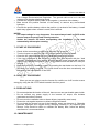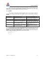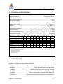
1
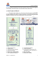
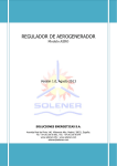
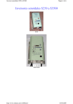
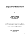
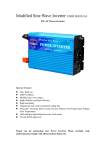
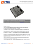
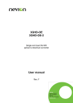
SOLENER Pure Sine Wave
Inverter
User Manual
Version 1.13
August 2013
Soluciones Energéticas S.A.
Avenida Real de Pinto, 146
28021 Villaverde alto, Madrid
Tel: +34 91-5050062
Fax: +34 91-5050079
www.solener.com – www.solener.info
[email protected]
Inverter User Manual
TABLE OF CONTENTS
1.- INVERTER DESCRIPTION
3
2.- FRONT PANEL INTERFACE
4
3.- INVERTER OPERATION
5
4.- INDICATORS AND SETTINGS
6
5.- INVERTER PROTECTIONS
5.1.- Overload Protection
7
5.2.- Over Temperature Protection
7
5.3.- Low and High Voltage Protection
7
6.- INSTALLATION INSTRUCTIONS
6.1.- Inverter Mounting
8
6.2.- Wiring
8
7.- START-UP PROCEDURE
9
8.- SHUT-OFF PROCEDURE
9
9.- PRECAUTIONS
9
10.- MAINTENANCE
9
11.- SAFETY INSTRUCTIONS
10
12.- TECHNICAL SPECIFICATIONS
11
13.- SERVICE CODES
11
14.- WARRANTY
12
Version 1.13, August 2013
2
Inverter User Manual
1.- INVERTER DESCRIPTION
The SOLENER inverter is a pure sine wave inverter (DC to AC converter),
designed for stand-alone photovoltaic applications and controlled by a microprocessor.
It has been designed to provide an alternating sinusoidal output voltage of 230 volts, 50
hertz (there are also versions of 120 volts and/or 60 hertz) from an input voltage of 12,
24, 36 or 48 volts provided from electrochemical accumulators. It employs state of the
art components, such as MOSFETs, 32-bit microcontrollers or LCD modules. In
addition to its basic inverter function, it allows monitoring of the photovoltaic installation
energy consumption, displaying information regarding energy, current intensity and
other operating parameters. It is manufactured with full-bridge configuration and uses
PWM (Pulse-Width Modulation) control.
The SOLENER inverter can supply energy to different loads such as resistive
loads (p. e. heater), inductive loads (refrigerators), motors (vacuum cleaners), and
rectified loads (computer). It can supply power surges (within its power range) to
provide the short peak of energy required to start some appliances or machines such
as TV’s, projectors, videos, computers, refrigerators, washing machines, submersible
pumps, sewage, heating boilers etc, without any difficulty.
The inverter protects itself against short circuit, overload, over-temperature,
voltage surge (overvoltage) and reverse polarity. Protection against reverse polarity
does not occur through the destruction of the input fuse (as it occurs in other
commercial inverters), it simply does not work.
Start-up and shutdown is possible through any PROFESSIONAL SOLENER®
CONTROLLER (using an optional control line). In addition, since the beginning of 2010
almost all versions feature a relay for generator start, which is activated (closing a
potential-free contact) when the battery needs recharging. This relay can be configured
to perform other functions; see some of these possible functions in section 13 or
consult your need with us.
This inverter reconnects automatically when the circumstances which caused
the shutdown have disappeared (e.g. battery over voltage or under voltage, overheating or a control signal sent from the controller). If it detects overload or short-circuit
following the elimination of the problem you will have to make a manual power cycle
(upon request, reset can be automatic).
Load detection is a special state (standby mode) whereby the inverter reduces
its power consumption to a minimum whilst waiting for a load equal to or greater than
the specified for its ignition. When it detects this load, the inverter starts and goes into
normal mode of operation. If power consumption falls below the set limit, the inverter
goes back into the detection mode. It is possible to adjust the load detection level from
0 Watts (continuous operation) up to about 100 Watts. If the power of the connected
load is lower than the specified threshold power, the inverter will start and stop once
per second until the load surpasses this set point. This will produce a characteristic
blinking (especially notable in light bulbs).
Versions prior to 4.00 have a potentiometer placed on the front panel to adjust
the load detection threshold, whilst in all other versions this is adjusted through the
menu, by pressing “Enter” and selecting the “Load threshold” option; when doing so, a
Version 1.13, August 2013
3
Inverter User Manual
bar whose length is proportional to the power required to exit the search mode appears
on the display. If the bar’s length is zero the search mode is deactivated.
2.- FRONT PANEL INTERFACE
The figures shown below are a front view of the three types of SOLENER®
inverters, showing all the elements of the user interface. These element references will
be used throughout this manual. The small model has one multi-color LED that brings
together the functions of the seven LEDs present in rest of the models.
1.
2.
3.
4.
5.
6.
7.
Alphanumeric Screen
Acoustic Alarm
Load Disconnection Indicator
Shortcircuit Indicator
Battery Over Voltage Indicator
Battery Under Voltage Indicator
Over Temperature Indicator
Version 1.13, August 2013
8. Load Detection Indicator
9. Power ON Indicator
10. Load Detection Potentiometer (For
versions prior to 4.00, see section 1)
11. ON / OFF switch
12. Setup Push Buttons
13. Relay Status Indicator
4
Inverter User Manual
3.- INVERTER OPERATION
After switching ON the inverter, the unit carries out system checking sequences;
if an error is detected the failure cause will be shown on the LCD display and the Load
Disconnection LED Indicator will start to flash along with other LED indicators
(depending on the failure). This type of failure does not allow the inverter to function
properly therefore it will cut power supply to the load. As part of this self-test process
the internal inverter fan will run for 1 second.
After the self-test process, the AC output voltage will gradually increase from
zero to its nominal value (soft start). If the load detection circuit is active and does not
find loads greater than those predetermined, then the inverter will go into load detection
(stand-by) mode reducing its power consumption and checking again once per second.
When the battery voltage is lower than the “low battery voltage” setting, the
acoustic alarm is activated and the “low battery” LED alarm begins flashing once per
second. After 10 seconds this LED alarm will remain lit and the “Load Disconnection”
LED will turn ON too, indicating that the inverter has been shut-off. If the battery
voltage rises reaching a voltage above the predetermined restart voltage, the inverter
will automatically start and both LEDs will turn OFF.
If the battery voltage reaches 4/3 of the inverter rated battery input voltage (e.g:
16 volts in a 12 volt inverter) the “Battery Over Voltage” LED turns ON in conjunction
with the “Load Disconnection” LED causing the AC output to shut-down. When the
inverter DC voltage input drops to a value lower than the re-start voltage setting, the
inverter will re-start automatically.
Inverters produce heat when operating. The amount of heat produced is
(almost) proportional to the amount of power supplied by the inverter. When the
MOSFET reaches a certain programmed temperature (50 ºC by default), the internal
fan is activated, stopping when the temperature drops below the preset temperature
limit (normally 40 ºC). However, if the temperature keeps on rising (because the
connected load is too high) and reaches 60 ºC, the output voltage will decrease by
10% in order to reduce the power; if despite this, the temperature keeps rising, the unit
will shut off when the temperature reaches 80 ºC, restarting again at 60 ºC. System
shut-down due to over temperature will be indicated by the corresponding yellow LED
alarm simultaneously with the red “load disconnection” LED (the screen also indicates
the cause of the load disconnection). Whilst the system is disconnected due to over
temperature the fan will continue functioning.
In models with input control, if this is not activated, the inverter will shut-down
and the “Load Disconnection” LED indicator will turn on. When it is activated, the
inverter restarts shutting off the correspondent LED alarm. Input control activation is
made by closing a circuit.
If a short-circuit is produced at the inverter output, the unit automatically limits
the output power to protect the installation, and the short-circuit LED lights up. If the
short-circuit lasts more than 10 seconds then the “Load Disconnection” LED will light
up and the inverter will stop. Once the cause of the short-circuit has been eliminated it
is necessary to reset the unit (using the ON/OFF switch) in order to recover the AC
output.
Version 1.13, August 2013
5
Inverter User Manual
When an AC overload is detected, the inverter limits the time that power is
supplied to the load (the time that this power will be supplied decreases as the
overload increases). Once this time has passed, the inverter output shuts off and the
“Load Disconnection” LED lights up. In order to recover full operation of the unit it will
be necessary to reset the unit again (using the ON / OFF switch).
4.- INDICATORS AND SETTINGS
The inverter is equipped with an alphanumeric LCD screen with 2 lines and 16
columns that displays information regarding the status of the inverter and the
installation. On the front panel there are also 8 LEDs which indicate (from bottom to
top):
•
•
•
•
•
•
•
•
Relay (Green): indicates that the relay is active (See section 1).
Power ON (Green): It indicates that the unit is functioning properly.
Load Detection (Green): it flashes when the inverter is in “Load Detection” mode,
and remains lit when it detects load. It turns off when the AC output is cut-off for
any given reason.
Over Temperature (Yellow): It turns on when the internal temperature is too high.
Low Battery Voltage (Yellow): It flashes when the battery voltage is low (acts as a
pre-disconnection alarm) and it remains lit (steady) when the inverter stops due to
low battery voltage.
High Battery Voltage (Yellow): It turns on when the battery voltage reaches 4/3 of
the inverter rated battery input voltage and turns off when it drops to a safe
operating voltage value.
Overload (Red): It flashes when a short-circuit takes place. It remains lit if it
exceeds the overload preset time.
Load Disconnection (Red): It turns ON when the inverter has shut-off (AC output
disconnected) to protect the installation or the inverter itself.
The yellow or red LED that remains lit together with the “Load Disconnection” LED
indicates the cause of the disconnection. If only the “Load Disconnection” LED is lit,
then the disconnection was caused by a signal coming from the external control line or
by a continuous overload. Information regarding the cause of the disconnection can be
found on the screen.
Simultaneously and as an additional aid, when the Battery Under Voltage” LED
alarm or the “Short-circuit” LED alarms are flashing, an acoustic alarm (50 millisecond
beep per second) will sound.
Information about the unit is displayed in sequence on screen, (e.g.: input / output
voltage and current, output power, peak power, energy consumption, internal
temperature, working time...), as well as the cause of disconnection, if applicable.
The load detection circuit is factory set to detect a load of (approximately) 1% of the
nominal power. If you intend to connect a load whose power consumption is lower than
this threshold, it may be necessary to add an additional load to ensure that the inverter
comes out of standby mode (Load Detection Mode).
The keypad allows the adjustment of some parameters, as well as resetting meter
(counter) values to zero and maximum/minimum levels of the variables. It also allows
Version 1.13, August 2013
6
Inverter User Manual
you to scroll manually from screen to screen or to maintain activated an individual
screen (always visible), when required. Pressing twice the central key will activate the
screen that provides input voltage and current readings, leaving it fixed.
5.- INVERTER PROTECTIONS
The inverter is protected against reverse polarity, overload, short-circuit, over
temperature and battery voltages out of a reasonable range. Please see below a
detailed description of each of the protections.
Contact our technical service ([email protected]) for factory setting of
automatic restart after overload or short-circuit.
5.1.- Overload Protection
See table in section 12 for overload limits.
The inverter gets latched in this condition. To reset, the power ON / OFF switch
is required to be switched OFF and ON again (manual start-up).
Before switching ON the inverter again, ensure that the cause of the
overload is removed.
5.2.- Over-Temperature Protection
As the inverter does not have, logically, 100% performance efficiency, it
dissipates the difference in form of heat, particularly when the unit is operating close to
its nominal power capacity. When the inverter is subject to a heavy load for a
prolonged period of time, the overheating protection will be triggered in three stages:
first activating its internal fan, then if the temperature keeps increasing it reduces the
output voltage by 10% and if temperature continues rising it cuts output voltage
altogether.
When the temperature drops down to a certain value, the unit starts
automatically.
5.3.- High and Low Battery Voltage Protection
The inverter can operate within the range of battery voltages between 5/6 and
4/3 of its nominal voltage. This range is adjusted in factory depending on the type of
battery that will be used. The battery model type can be selected using the Installer
password.
Shutdown due to low DC input voltage prevents the battery from fully
discharging, otherwise it can cause irreversible damage to the battery. A delay time
has been foreseen in the control circuit allowing the battery voltage to drop
momentarily below these limits; this makes it possible to start induction motors or cold
filament lamps with this inverter. The “Low Battery Voltage” LED alarm will flash while
Version 1.13, August 2013
7
Inverter User Manual
the preset voltage threshold is not reached, and remains lit after 10 seconds, shutting
off the output.
Shut-down due to high DC input voltage is intended to protect the inverter
against irreversible damages.
In both cases, when the battery voltage returns to a value within the acceptable
working range, the unit will automatically restart. (After a shut-down due to low DC
input voltage, the voltage has to raise significantly in order to allow the battery to
recover).
6.- INSTALLATION
6.1.- Inverter Mounting
The inverter must be fixed on a vertical surface, with its connection wires at the
bottom of the unit and with at least 5 cm clearance at the top and at the bottom for
adequate airflow. It should be placed high enough so that it is out of the reach of
children and animals.
The inverter should be fitted using screws placed through the four holes
provided for such purpose. The lock-shaped holes allows you to place the screws in
the wall before you put the inverter, and tightening them later.
6.2.- Wiring
The inverter has three or four cable holders located in the bottom part, from which
the following cables come out:
•
•
•
•
A red cable (or with a red terminal) to connect to the positive (+) terminal of the
battery.
A black (or blue) cable to connect to the negative (-) terminal of the battery.
A three wire cable (phase, neutral and ground) or an industrial connector for
connection to the AC loads.
An optional two wire cable to connect to the remote control.
Battery cables have a terminal at the end which must be attached with bolts to the
terminals of the battery. DO NOT EXTEND THESE CABLES. Be sure to properly
fasten these bolts and retighten them after a few days. You must also make sure that
all bolts used with battery connecting cables (jumper wire) are tight. If during the
operation of the inverter any battery connecting cable is hotter than others, you should
tighten its bolts and/or clean both battery terminals and connecting battery cables ends.
Before connecting the unit ensure that the ON/OFF switch on the front panel is in
the OFF position and that the house RCD (residual-current device, also known as GFI
(ground fault interrupter) in U. S. and Canada) is open, then proceed as follows:
•
Connect the AC wires to the external output breaker. Live cable is brown, gray or
black, the neutral cable is blue and ground cable is yellow and green. Neutral and
ground cables are connected to the casing of the unit. Unit casing should be
connected to an earthing rod that complies with the specifications described in the
Version 1.13, August 2013
8
Inverter User Manual
•
•
•
Low Voltage Electro-technical Regulation. The ground cable must be in the low
voltage circuit breaker distribution board.
Connect the negative battery cable to the negative (-) terminal of the battery.
Blow around the positive terminal of the battery to remove any accumulated
hydrogen.
Connect the positive battery cable to the positive (+) terminal of the battery. A small
spark may appear when contact is made, this is normal.
NOTES:
- AC output voltage is very dangerous. You must always install an RCD at the
inverter output for people and animal protection.
- Switch the inverter off before manipulating the installation; it can start
automatically without prior warning.
7.- START-UP PROCEDURE
•
•
•
•
•
Check all the connections to make sure that they are all correct.
Turn the inverter on using the ON / OFF switch located on the front panel.
Close the AC output breaker that you connected to the inverter output.
If the load connected to the inverter is higher than that adjusted with the “load
detection” potentiometer, the inverter will start and the output voltage will increase
rapidly until it reaches its nominal value. If not, load will turn ON and OFF once per
second.
Verify that the RCD is working properly by pressing the test button on the front, if it
trips then it is working properly. This cross-check must be done occasionally, as
indicated by the manufacturer of the RCD.
8.- SHUT-OFF PROCEDURE
When you are not going to use the inverter for a while, turn it off in order to save
energy by using the ON / OFF switch located in the front panel.
9.- PRECAUTIONS
•
•
•
•
•
Do not manipulate the interior of the unit, there are no user serviceable parts inside.
Do not connect any power supply to the inverter AC output, this includes
generators and other inverters.
Do not cover the ventilation slots or insert objects (especially metal ones).
Protect the unit against exposure to direct sunlight and water.
Do not install the inverter on top of the batteries, gases can damage it. Batteries
generate hydrogen and oxygen during charging, resulting in an explosive gas
mixture. Care should be taken to ventilate the battery area; follow the battery
manufacturer’s recommendations.
10.- MAINTENANCE
Version 1.13, August 2013
9
Inverter User Manual
The inverter does not require any special maintenance. Periodic cleaning of the
casing with a dry cloth is recommended. If necessary, a dampened cloth with soapy
water can be used (never dampen with alcohol or solvents).
11. – SAFETY
The inverter is reasonably protected against most of the possible causes of
damage. The following table shows the possible causes of disconnection and their
solutions.
FAILURE
RESULT
SOLUTION
Over-temperature
“Load Disconnection” and
“Overtemperature” LED alarms will turn
on.
Inverter does nothing.
“Load Disconnection” and Shortcircuit”
(if applicable) LED alarms will turn on.
Inverter automatically restarts when
temperature reaches the normal values.
Reverse Polarity
Overload or short-circuit
High Battery voltage
“Load Disconnection” and “High Battery
Voltage”LED alarms turn on.
Low Battery voltage
“Load Disconnection” and “Low Battery
Voltage”LED alarms turn on.
Connect the battery correctly.
Turn OFF the inverter, eliminate the
cause of shortcircuit or overload. Reset
the inverter by using the ON/OFF switch.
Inverter automatically restarts when
battery voltage drops to reconnection
voltage.
Inverter automatically restarts when
battery voltage rises to reconnection
voltage.
If you restart the inverter after a low battery voltage disconnection then the it will
work for a while before shutting down again. This is normal, because the battery is still
depleted. You must wait for the battery to recharge partially, and the best way to
achieve this is using the automatic restart feature of the inverter.
Version 1.13, August 2013
10
Inverter User Manual
12.- TECHNICAL SPECIFICATIONS
Output wave form.......................................................................................................... Pure Sine Wave
Rated output voltage ............................................................................................ 230 (120 optional) VAC
Rated output frequency ............................................................................................. 50 (60 optional) Hz
Output frequency variations ......................................................................................................... < 0,1 %
Output power variations ................................................................................................................... < 5 %
Minimum Input Voltage ................................................................................................................ 5/6 Vnom
Maximum Input Voltage ............................................................................................................... 4/3 Vnom
Efficiency ......................................................................................................................................85-97 %
Efficiency with nominal load .......................................................................................................... > 85 %
Consumption (in detection)......................................................................................................... < 70 mA
Harmonic Distortion ......................................................................................................................... < 5 %
Environmental Protection Level ........................................................................................................ IP20
Relay Maximum Current ....................................................................................................... 1 A resistive
Rated Power(VA)
500
750
1000
1250
1500
2200
2500
3000
4200
6000
Rated Voltage (V)
12/24
12
24
12
24
12
24/36/48
12
24/36/48
24/36/48
48
Overload 3 ’’ (VA)
750
1100
1500
1800
2200
3300
3700
4500
6300
9000
15000
Overload 50 ’’ (VA)
650
1000
1300
1600
1900
2800
3200
3900
5400
7800
13000
Overload 6 ’ (VA)
600
900
1200
1500
1800
2600
3000
3600
5000
7200
12000
Length (mm)
115
315
315
315
460
460
460
535
535
535
647
Height (mm)
230
118
118
118
157
157
157
178
178
178
210
Width (mm)
154
192
192
192
255
255
255
285
285
285
344
Net Weight (kg)
Relay (see Section 1)
10000
4
9
9
12
20
22
22
24
36
36
68
NO
NO
NO
NO
NO
YES
YES
YES
YES
YES
YES
PROTECTIONS
•
Against Reverse Polarity (using intelligent diode)
•
Against High and Low Voltage
•
Against Shortcircuit and Overload
•
Against Over Temperature
36 V input or 120 V / 60 Hz output available upon request. Aluminum casing protected with epoxy paint. DATA SUBJECT TO CHANGE WITHOUT NOTICE.
13.- SERVICE CODES
These codes are an excerpt of those that can be used in the Service option in
the menu to change the relay mode of operation:
65435470 ................................. Relay contacts close to start generator (default value)
65435471 ......................................................... Relay contacts open to start generator
6243547E ..............................................Relay contacts close when power is too high
66435476 ................................ Relay contacts close when there is low battery voltage
61435478 .......................................... Relay contacts close when AC output is shut-off
6043547A ..................................Relay contacts close when there is over temperature
Version 1.13, August 2013
11
Inverter User Manual
14.- WARRANTY
SOLUCIONES ENERGÉTICAS, S.A. guarantees that its products comply
with all written specifications in this manual.
The warranty period of SOLENER products are 2 years, which will begin
to take effect from product shipment date from SOLUCIONES ENERGÉTICAS
S.A. or, if it is sold to an authorized retailer, from the authorized retailer
shipment date to the customer.
SOLUCIONES ENERGÉTICAS, S.A. may, at its discretion and cost, repair
or replace products for new or reconditioned ones, provided they are returned
by the buyer together with date and proof of purchase.
If, SOLUCIONES ENERGÉTICAS S.A., after examining and testing any
product returned by the buyer for repairing or replacement, finds, that such
product is not faulty, he will inform the customer and will dispose of the product
according to customers instructions with costs bared by the customer, and the
customer shall pay to SOLUCIONES ENERGÉTICAS S.A. the costs incurred to
examine and test the product according to prevailing rates.
The warranty is solely limited to the repair (materials and labor) of the
equipment, in no case includes travel expenses, freight or shipping costs, or
any damage caused by the use of or inability to use the equipment. The use of
our products in life support devices without the express written permission of
our company President is specifically prohibited.
The use or continued possession of the products after the expiration
of the warranty period, shall be deemed as conclusive evidence that the
warranty has been fulfilled to the full satisfaction of the buyer.
The warranty set forth above shall not apply to the faults or defects caused
by misuse, abnormal use or product abuse, or by negligence, alteration,
improper installation, opening, unauthorized modification, inadequate testing,
entry of foreign bodies, animals or gases, accidents or external causes to the
product, including those of force majeure such as earthquakes, hurricanes or
floods.
In case of non acceptance of the warranty terms and conditions,
equipment must be returned in a term not exceeding 15 days with all original
accessories and in its original packaging.
Version 1.13, August 2013
12