1
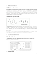
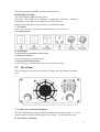
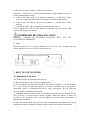
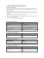
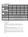
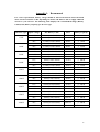
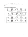
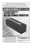
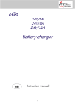
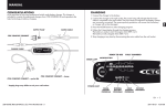
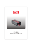
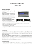
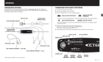
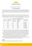
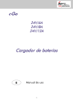
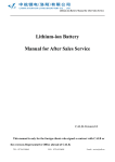
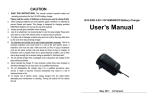
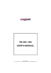
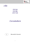
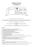
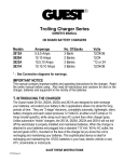
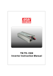
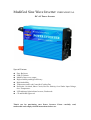
Modified Sine Wave Inverter USER MANUAL DC-AC Power Inverter Special Feature: Fuse: Built-out USB:5V,500mA Modified sine wave output High reliability and high efficiency High load ability Temperature and Load Controlled Cooling Fan Protection: Overload, Short Circuit, Reverse Polarity, Over/Under Input Voltage, Over Temperature. LED indicator light indicate Inverter, Fault mode. CE and RoHS Approved. Thank you for purchasing ours Power Inverter. Please carefully read, understand and comply with all instructions before use. Table of contents 1. Introduction………………………………………………………….3 1.1 What’s an inverter…………………………………………….3 1.2 Select the right waveform……………………………………..3 2. Main Components…………………………………………………..3 2.1 Front panel…………………………………………………….3 2.2 Rear panel……………………………………………………..4 3. How to Use Inverter….……………………………………..………5 3.1 Placement of the inverter……………………………………..5 3.2 Mounting position of the inverter……………………………6 3.3 Getting Connected…………………………………………….6 4. Important Safety Instructions………………………………………7 5. Protection Feature…………………………………………………...8 6. Troubleshooting Reference………………………………………….8 7. Specifications………………………………………...........................9 8. Maintenance…………………………………………………………..9 9. Warranty……………………………………………………………...9 Appendix I: Recommend………..……………………………...……..10 Appendix I I: Battery Wiring Examples………...………………...…11 Notice that specifications and product functionality may change without notice. 2 1. INTRODUCTION 1.1 What is an Inverter? Power inverter is an electronic device that converters low voltage DC(Direct Current) electricity from a battery or other power source to 100V-120V or 220V-240V AC(Alternating Current) household power. DC is the power that is produced by battery or other power source while AC is the standard power needed to run electrical equipment. A power inverter does the opposite of a rectifier and is used in places and situations where AC power is not available. 1.2 Select the right waveform Modified Sine Wave: If your equipment can accept some voltage fluctuation, consider a modified sine wave inverter. These inverters provide mobile power at a more affordable price and come in a full range of size-from handheld to high performance. Do not use to power sensitive devices such as medical equipment or computers. Some audio equipment may perform poorly if run on Modified Sine Wave power. 2. MAIN COMPONENTS 2.1 Front Panel The front panel view shows the inverter’s ON/OFF Switch, AC Outlet, LED Indicator Light, Vent Outlet, USB A. ON/OFF Switch. 3 This switch controls ON/OFF operation of the inverter. B.LED Indicator Light Two LED indicator light: Inverter, Fault. a)Inverter: This light will illuminate continuously whenever connected equipment is receiving battery-supplied, inverted AC power. b)Fault: Turns Red shows fault, reference to Troubleshooting. C. AC Outlet. Outlet sockets available: North America, Europe(schuko), UK, Australia, etc. AC Output Optional: D. Vent Outlet. To decrease the temperature of the inverter. E. USB Port:5V,500mA Powers and charges USB-enabled devices. G: Remote Switch Port(Optional): Use to connect the remote ON/OFF switch via a communication cable. 2.2 Rear Panel The rear panel view shows the inverter’s Cooling fan, DC Battery Terminals, Fuse. A. Cooling fans/ Ventilation Windows The fans automatically operate when the internal temperature(exceeds 45ºC) of the inverter requires cooling. Always allow free air flow – do not block the vents. B. DC Battery Terminals 4 Connect the inverter to battery or other power sources. Negative (-) and Positive (+) DC terminals should be kept insulated to protect from accidental short circuits. a) Connect the black cable to the black post marked (-) on the back of the inverter. Connect the other end to the negative terminal on the battery. b) Connect the red cable to the red post marked (+) on the back of the inverter. Connect the other end to the positive terminal on the battery. If you connect the cables to the incorrect terminals, you will reverse the polarity and damage the inverter. PROHIBITED REVERSE POLARITY. DAMAGE CAUSED BY REVERSE POLARITY WILL NOT BE COVERED BY WARRANTY. C. Fuse Fuse was built-out is a very good design as you can very easy to change the fuse outside the inverter if your inverter fuse was blown. 3. HOW TO USE INVERTER 3.1 Placement of inverter The location where to install inverter must be: A. Dry: Do not allow water to drip or splash onto it. B. Cool: Ambient air temperature should be between 0º C and 40º C - ideally between 15º C and 25º.Do not place the inverter on or near a heating vent or any piece of equipment which is generating heat above room temperature. Do not place the inverter in direct sunlight unnecessarily. C. Ventilated: Allow at least one inch of clearance around the unit for air flow. Do not place items on or over the inverter during operation. Make sure that air is allowed to circulate freely around the unit. A fan is helpful in the case where the inverter is operating at maximum D. Safe: Do not install the inverter in the same compartment as the batteries or in any compartment where flammable liquids or fumes may be or may become present. 5 E. Dust Do not install the inverter in a dusty environments. The dust can be inhaled into the unit when the cooling fan is working. F. Close to batteries: Avoid excessive cable lengths. Do not install the inverter in the same compartment as batteries. 3.2 Mounting position of the inverter The inverter may be mounted horizontally on the top of a horizontal surface or under a horizontal surface. The inverter may be mounted on a vertical surface only horizontally. 3.3 Getting Connected. To get going, follow these easy steps. 1.Power supply selection - It must get power from storage battery/batteries or a car cigarette lighter port. 2.Connect inverter to power supply. Set the switches into the OFF position(including inverter and appliances). a. Get power from battery/batteries: Connect the DC cables to the DC battery terminals on the rear panel of the inverter. The red terminal is positive (+) and the black terminal is negative (-). b. Get power from car cigarette lighter port, insert the car cigarette lighter plug into the car cigarette lighter port. 3. Connect inverter to appliances. Make sure the load power within the rated power of inverter and the start power should not exceed the peak power of the inverter. When having the inverter connected with appliances and a power supply, switch on the inverter and appliances. 4.IMPORTANT SAFETY INSTRUCTIONS Incorrect installation and misuse of the inverter may result in danger to the user or hazardous conditions. 1. Do not attempt to connect the any other power source, including any AC power source . 2. Make sure the opening to the ventilation fan and vent holes are not blocked. 3. Avoid pulling on the cords and cables. Always grip plugs firmly when unplugging from power source and when disconnecting cables. 4. To avoid electrical hazard, be sure to unplug the inverter from its external power source before inserting the AC plug. 5. For indoor use only. Avoid exposure to external heat sources; direct, prolonged sunlight; dust; corrosive chemicals; and moisture. 6. It is normal for inverters to become warm during use. Avoid touching the device during use. Avoid placing in direct sunlight or near heat-sensitive materials. 7. Do not drop or subject the inverter to undue shock. 6 8. Do not place anything on top of the inverter. 9. Always with the supplied cables and connectors as shown. Use of cables, connectors, or accessories not supplied with this product constitutes misuse and may result in injury or damage. 10. Do not attempt to service or dissemble. The unit is not user-serviceable. Attempting to disassemble or service the unit can result in electrical hazard, including death from exposure to high voltage. If you experience problems with the unit, discontinue use and Contact Technician. 11. When cleaning the inverter, please switch off power(unplug the inverter).Carefully clean with dry cloth. Do not use wet cloth or cleanser. 12. Disconnect all AC and DC side connections before working on any circuits associated with the inverter. Turning the ON/OFF switch on the inverter to off position may not entirely remove dangerous voltage. 13. Keep away from children. 5. PROTECTION FEATURE Inverter is equipped with numerous protection features to ensure safe operation. Input Low Voltage Protection A: When battery voltage is below 10.5V±0.5V(for 12V input inverter)/21V±1.0V(for 24V input inverter)/ 42V±2.0V(for 48V input inverter), a buzzer will alarm, which indicates DC power supply voltage is descending and batteries need to recharge. B: When input voltage is below 10V±0.5V(for 12V input inverter)/20V±1.0V(for 24V input inverter)/ 40V±2.0V(for 48V input inverter), AC output will be automatically shut off, a buzzer alarm and ALARM/WARNING light turns red at the same time. Input Over Voltage Protection When input voltage reach 15V±0.5V (for 12V input inverter)/30V±1.0V (for 24V input inverter)/60V±2.0V (for 48V input inverter),ALARM/WARNING light turns red and the AC output will be shut off automatically. Short Circuit Protection When short circuits occur, output will be shut off and ALARM/WARNING light turns red. Overload Protection When overloads occur, output will be shut off and ALARM/WARNING light turns red. Reverse polarity protection When battery terminals are reverse connected, fuse will be burned to protect appliances. Over Temperature Protection When heat sink temperature exceeds 45ºC, the inner cooling fan will automatically turn on to cool the inverter; when less than 30ºC,the inner cooling fan will automatically shut off. When inner temperature exceeds 70ºC, AC output will automatically shut off, ALARM/WARNING light turns red. It is unusable for 15 minutes. 7 6.TROUBLESHOOTING REFERENCE Acoustics buzzer alarms When applying the inverter to acoustics devices, some inferior acoustics devices will buzz, this is because the output wave from the inverter is modified sine wave inverter. TV Interference You can get minimum interference through use of a filter. On some occasions, when the interference of every weak signals becomes too obvious, you can try the following: Place the inverter far from the TV and TV antenna. Try to change the direction of TV signals cable and TV antenna to reduce the interference to minimum. Use screen cable antenna of highly quality. Problem: No output voltage Possible Causes Battery voltage too low Overload Inverter thermal protection Solution Recharge or replace the battery Reduce the load Cool the inverter and place it in the place with good ventilation; Reduce the load. Inverter start-up fail Repeat starting the inverter Reverse polarity connection and fuse Replace the fuse with a fuse of equivalent melted value. Problem: Inverter no response Possible Causes Poor contact between battery and inverter Reverse polarity connection and fuse melted Problem: Output voltage low Possible Causes Input voltage too low Overload Problem: Low voltage alarm Possible Causes Battery no power Battery voltage too low or connection Solution Reconnect them Replace the fuse with a fuse of equivalent value. Solution Make sure input voltage is within the rated range. Reduce the load Solution Recharge the battery poor Recharge the battery, check terminals connection or clean terminal with a dry cloth 8 7.Specifications Items Continuous power Surge Power PCS/CTN Packing KGS/CTN Dimension(MM) Items Continuous power Surge Power PCS/CTN Packing KGS/CTN Dimension(MM) Input voltage Output voltage Output Frequency Efficiency Output Waveform SR-150-M 150W 300W 16 16.5 435*370*370 SR-1500-M 1500W 3000W 2 10.5 430*305*355 Models SR-300-M SR-500-M SR-600-M 300W 500W 600W 600W 1000W 1200W 16 16 16 17 18 19 435*370*370 435*370*370 435*370*370 Models SR-2000-M SR-2500-M SR-3000-M 2000w 2500W 3000W 4000W 5000W 6000W 2 2 2 12 14.5 15 430*305*355 450*305*355 495*360*500 12V / 24V/ 48V 100~120VAC / 200~240VAC (Optional) 50Hz±0.1% or 60Hz±0.1% (Optional) >88% 50Hz±0.1% or 60Hz±0.1% (Optional) SR-1000-M 1000W 2000W 6 16 420*340*460 Protection Low Voltage Alarm,Low Voltage Shut down, Over Voltage Shut down,Over temperature, Over load,Short circuit, Reverse Polarity Battery typs Open & sealed lead acid battery Note: *The specifications are subject to change without prior notice for further improvement of products. 8.Maintenance To keep your inverter operating properly, there is very little maintenance required. You should clean the exterior periodically with a dry cloth to prevent accumulation of dust and dirt. At the same time, tighten the screws on the DC input terminals. 9.Warranty We guarantee this product against defects in materials and workmanship for a period of one year from the date of retail purchase by end user. This warranty will be considered void if the unit has been misused, altered, or accidentally damaged. We are not liable for anything that occurs as a result of the user’s fault. If the warranty period for your product has expired, if the unit was damaged by misuse or incorrect installation, if other conditions of the warranty have not been met, or if no dated proof of purchase is available, your unit may be serviced or replaced for a flat fee. 9 Appendix I: Recommend For correct operation,the battery voltage should be between 0.9xVnom and 1.29xVnom where Vnom is 12V,24V or 48V depending on model, and must be able to supply sufficient current to your inverter. The following table displays the recommended things (Battery Cables,Fuses,Battery Capacity) per inverter type. Inverter Type 150W 300W 500W 600W 1000W 1500W 2000W 2500W 3000W Input Voltage DC Battery Cable Fuse Battery Capacity 12V 2.5mm²(1*red/1*black) 35A*1 ≥ 25Ah 24V 2.5mm²(1*red/1*black) 20A*1 ≥ 12Ah 48V 2.5mm²(1*red/1*black) 10A*1 ≥ 10Ah 12V 4mm²(1*red/1*black) 35A*1 ≥ 50Ah 24V 2.5mm²(1*red/1*black) 20A*1 ≥ 25Ah 48V 2.5mm²(1*red/1*black) 10A*1 ≥ 12Ah 12V 6mm²(1*red/1*black) 35A*4 ≥ 100Ah 24V 4mm²(1*red/1*black) 20A*4 ≥ 50Ah 48V 2.5mm²(1*red/1*black) 10A*4 ≥ 25Ah 12V 6mm²(1*red/1*black) 35A*4 ≥ 100Ah 24V 4mm²(1*red/1*black) 20A*4 ≥ 50Ah 48V 2.5mm²(1*red/1*black) 10A*4 ≥ 25Ah 12V 10mm²(1*red/1*black) 35A*4 ≥ 160Ah 24V 6mm²(1*red/1*black) 20A*4 ≥ 80Ah 48V 4mm²(1*red/1*black) 10A*4 ≥ 40Ah 12V 10mm²(2*red/2*black) 35A*6 ≥ 250Ah 24V 6mm²(2*red/2*black) 20A*6 ≥ 125Ah 48V 4mm²(2*red/2*black) 10A*6 ≥ 60Ah 12V 16mm²(2*red/2*black) 35A*8 ≥ 320Ah 24V 10mm²(2*red/2*black) 20A*8 ≥ 160Ah 48V 6mm²(2*red/2*black) 10A*8 ≥ 80Ah 12V 16mm²(2*red/2*black) 35A*10 ≥ 400Ah 24V 10mm²(2*red/2*black) 20A*10 ≥ 200Ah 48V 6mm²(2*red/2*black) 10A*10 ≥ 100Ah 12V 16mm²(2*red/2*black) 35A*12 ≥ 480Ah 24V 10mm²(2*red/2*black) 20A*12 ≥ 240Ah 48V 6mm²(2*red/2*black) 10A*12 ≥ 120Ah 10 Appendix I I : Battery Wiring Examples In renewable energy systems, batteries are connected to each other in one of three ways: • Series (voltage increases, amperage stays the same as a single battery) • Parallel (voltage stays the same as a single battery, amperage increases) • Series/Parallel (both voltage and amperage increase) 11 12