1
User’s Manual
MKP 3000 Series
www.extron.com
Extron Electronics, USA
1230 South Lewis Street
Anaheim, CA 92805
800.633.9876 714.491.1500
FAX 714.491.1517
Extron Electronics, Europe
Beeldschermweg 6C
3821 AH Amersfoort, The Netherlands
+800.3987.6673 +31.33.453.4040
FAX +31.33.453.4050
Extron Electronics, Asia
135 Joo Seng Rd. #04-01
PM Industrial Bldg., Singapore 368363
+800.7339.8766 +65.6383.4400
FAX +65.6383.4664
© 2007 Extron Electronics. All rights reserved.
Extron Electronics, Japan
Kyodo Building, 16 Ichibancho
Chiyoda-ku, Tokyo 102-0082
Japan
+81.3.3511.7655 FAX +81.3.3511.7656
Remote Control Panels
68-1069-01 Rev. C
04 07
Precautions
Safety Instructions • English
This symbol is intended to alert the user of important
operating and maintenance (servicing) instructions
in the literature provided with the equipment.
This symbol is intended to alert the user of the
presence of uninsulated dangerous voltage within
the product's enclosure that may present a risk of
electric shock.
Caution
Read Instructions • Read and understand all safety and operating
instructions before using the equipment.
Retain Instructions • The safety instructions should be kept for future
reference.
Follow Warnings • Follow all warnings and instructions marked on the
equipment or in the user information.
Avoid Attachments • Do not use tools or attachments that are not
recommended by the equipment manufacturer because they may be
hazardous.
Consignes de Sécurité • Français
Ce symbole sert à avertir l’utilisateur que la
documentation fournie avec le matériel contient des
instructions importantes concernant l’exploitation
et la maintenance (réparation).
Ce symbole sert à avertir l’utilisateur de la présence
dans le boîtier de l’appareil de tensions dangereuses
non isolées posant des risques d’électrocution.
Attention
Lire les instructions• Prendre connaissance de toutes les consignes de
sécurité et d’exploitation avant d’utiliser le matériel.
Conserver les instructions• Ranger les consignes de sécurité afin de
pouvoir les consulter à l’avenir.
Respecter les avertissements • Observer tous les avertissements et
consignes marqués sur le matériel ou présentés dans la documentation
utilisateur.
Eviter les pièces de fixation • Ne pas utiliser de pièces de fixation ni
d’outils non recommandés par le fabricant du matériel car cela
risquerait de poser certains dangers.
Sicherheitsanleitungen • Deutsch
Dieses Symbol soll dem Benutzer in der im
Lieferumfang enthaltenen Dokumentation
besonders wichtige Hinweise zur Bedienung und
Wartung (Instandhaltung) geben.
Dieses Symbol soll den Benutzer darauf aufmerksam
machen, daß im Inneren des Gehäuses dieses
Produktes gefährliche Spannungen, die nicht isoliert
sind und die einen elektrischen Schock verursachen
können, herrschen.
Achtung
Lesen der Anleitungen • Bevor Sie das Gerät zum ersten Mal verwenden,
sollten Sie alle Sicherheits-und Bedienungsanleitungen genau
durchlesen und verstehen.
Aufbewahren der Anleitungen • Die Hinweise zur elektrischen Sicherheit
des Produktes sollten Sie aufbewahren, damit Sie im Bedarfsfall darauf
zurückgreifen können.
Befolgen der Warnhinweise • Befolgen Sie alle Warnhinweise und
Anleitungen auf dem Gerät oder in der Benutzerdokumentation.
Keine Zusatzgeräte • Verwenden Sie keine Werkzeuge oder Zusatzgeräte,
die nicht ausdrücklich vom Hersteller empfohlen wurden, da diese eine
Gefahrenquelle darstellen können.
Instrucciones de seguridad • Español
Este símbolo se utiliza para advertir al usuario sobre
instrucciones importantes de operación y
mantenimiento (o cambio de partes) que se desean
destacar en el contenido de la documentación
suministrada con los equipos.
Este símbolo se utiliza para advertir al usuario sobre
la presencia de elementos con voltaje peligroso sin
protección aislante, que puedan encontrarse dentro
de la caja o alojamiento del producto, y que puedan
representar riesgo de electrocución.
Precaucion
Leer las instrucciones • Leer y analizar todas las instrucciones de
operación y seguridad, antes de usar el equipo.
Conservar las instrucciones • Conservar las instrucciones de seguridad
para futura consulta.
Obedecer las advertencias • Todas las advertencias e instrucciones
marcadas en el equipo o en la documentación del usuario, deben ser
obedecidas.
Evitar el uso de accesorios • No usar herramientas o accesorios que no
sean especificamente recomendados por el fabricante, ya que podrian
implicar riesgos.
Extron’s Warranty
Warning
Power sources • This equipment should be operated only from the power source
indicated on the product. This equipment is intended to be used with a main
power system with a grounded (neutral) conductor. The third (grounding) pin is
a safety feature, do not attempt to bypass or disable it.
Power disconnection • To remove power from the equipment safely, remove all
power cords from the rear of the equipment, or the desktop power module (if
detachable), or from the power source receptacle (wall plug).
Power cord protection • Power cords should be routed so that they are not likely to
be stepped on or pinched by items placed upon or against them.
Servicing • Refer all servicing to qualified service personnel. There are no userserviceable parts inside. To prevent the risk of shock, do not attempt to service
this equipment yourself because opening or removing covers may expose you to
dangerous voltage or other hazards.
Slots and openings • If the equipment has slots or holes in the enclosure, these are
provided to prevent overheating of sensitive components inside. These openings
must never be blocked by other objects.
Lithium battery • There is a danger of explosion if battery is incorrectly replaced.
Replace it only with the same or equivalent type recommended by the
manufacturer. Dispose of used batteries according to the manufacturer's
instructions.
Extron Electronics warrants this product against defects in materials and
workmanship for a period of three years from the date of purchase. In the event of
malfunction during the warranty period attributable directly to faulty workmanship
and/or materials, Extron Electronics will, at its option, repair or replace said products
or components, to whatever extent it shall deem necessary to restore said product to
proper operating condition, provided that it is returned within the warranty period,
with proof of purchase and description of malfunction to:
USA, Canada, South America,
and Central America:
Extron Electronics
Avertissement
1001 East Ball Road
Alimentations• Ne faire fonctionner ce matériel qu’avec la source d’alimentation
indiquée sur l’appareil. Ce matériel doit être utilisé avec une alimentation
principale comportant un fil de terre (neutre). Le troisième contact (de mise à la
terre) constitue un dispositif de sécurité : n’essayez pas de la contourner ni de la
désactiver.
Déconnexion de l’alimentation• Pour mettre le matériel hors tension sans danger,
déconnectez tous les cordons d’alimentation de l’arrière de l’appareil ou du
module d’alimentation de bureau (s’il est amovible) ou encore de la prise secteur.
Protection du cordon d’alimentation • Acheminer les cordons d’alimentation de
manière à ce que personne ne risque de marcher dessus et à ce qu’ils ne soient
pas écrasés ou pincés par des objets.
Réparation-maintenance • Faire exécuter toutes les interventions de réparationmaintenance par un technicien qualifié. Aucun des éléments internes ne peut être
réparé par l’utilisateur. Afin d’éviter tout danger d’électrocution, l’utilisateur ne
doit pas essayer de procéder lui-même à ces opérations car l’ouverture ou le
retrait des couvercles risquent de l’exposer à de hautes tensions et autres dangers.
Fentes et orifices • Si le boîtier de l’appareil comporte des fentes ou des orifices,
ceux-ci servent à empêcher les composants internes sensibles de surchauffer. Ces
ouvertures ne doivent jamais être bloquées par des objets.
Lithium Batterie • Il a danger d'explosion s'll y a remplacment incorrect de la
batterie. Remplacer uniquement avec une batterie du meme type ou d'un ype
equivalent recommande par le constructeur. Mettre au reut les batteries usagees
conformement aux instructions du fabricant.
Anaheim, CA 92805, USA
Vorsicht
Stromquellen • Dieses Gerät sollte nur über die auf dem Produkt angegebene
Stromquelle betrieben werden. Dieses Gerät wurde für eine Verwendung mit
einer Hauptstromleitung mit einem geerdeten (neutralen) Leiter konzipiert. Der
dritte Kontakt ist für einen Erdanschluß, und stellt eine Sicherheitsfunktion dar.
Diese sollte nicht umgangen oder außer Betrieb gesetzt werden.
Stromunterbrechung • Um das Gerät auf sichere Weise vom Netz zu trennen,
sollten Sie alle Netzkabel aus der Rückseite des Gerätes, aus der externen
Stomversorgung (falls dies möglich ist) oder aus der Wandsteckdose ziehen.
Schutz des Netzkabels • Netzkabel sollten stets so verlegt werden, daß sie nicht
im Weg liegen und niemand darauf treten kann oder Objekte darauf- oder
unmittelbar dagegengestellt werden können.
Wartung • Alle Wartungsmaßnahmen sollten nur von qualifiziertem
Servicepersonal durchgeführt werden. Die internen Komponenten des Gerätes
sind wartungsfrei. Zur Vermeidung eines elektrischen Schocks versuchen Sie in
keinem Fall, dieses Gerät selbst öffnen, da beim Entfernen der Abdeckungen die
Gefahr eines elektrischen Schlags und/oder andere Gefahren bestehen.
Schlitze und Öffnungen • Wenn das Gerät Schlitze oder Löcher im Gehäuse
aufweist, dienen diese zur Vermeidung einer Überhitzung der empfindlichen
Teile im Inneren. Diese Öffnungen dürfen niemals von anderen Objekten
blockiert werden.
Litium-Batterie • Explosionsgefahr, falls die Batterie nicht richtig ersetzt wird.
Ersetzen Sie verbrauchte Batterien nur durch den gleichen oder einen
vergleichbaren Batterietyp, der auch vom Hersteller empfohlen wird. Entsorgen
Sie verbrauchte Batterien bitte gemäß den Herstelleranweisungen.
Advertencia
Alimentación eléctrica • Este equipo debe conectarse únicamente a la fuente/tipo
de alimentación eléctrica indicada en el mismo. La alimentación eléctrica de este
equipo debe provenir de un sistema de distribución general con conductor
neutro a tierra. La tercera pata (puesta a tierra) es una medida de seguridad, no
puentearia ni eliminaria.
Desconexión de alimentación eléctrica • Para desconectar con seguridad la
acometida de alimentación eléctrica al equipo, desenchufar todos los cables de
alimentación en el panel trasero del equipo, o desenchufar el módulo de
alimentación (si fuera independiente), o desenchufar el cable del receptáculo de
la pared.
Protección del cables de alimentación • Los cables de alimentación eléctrica se
deben instalar en lugares donde no sean pisados ni apretados por objetos que se
puedan apoyar sobre ellos.
Reparaciones/mantenimiento • Solicitar siempre los servicios técnicos de personal
calificado. En el interior no hay partes a las que el usuario deba acceder. Para
evitar riesgo de electrocución, no intentar personalmente la reparación/
mantenimiento de este equipo, ya que al abrir o extraer las tapas puede quedar
expuesto a voltajes peligrosos u otros riesgos.
Ranuras y aberturas • Si el equipo posee ranuras o orificios en su caja/alojamiento,
es para evitar el sobrecalientamiento de componentes internos sensibles. Estas
aberturas nunca se deben obstruir con otros objetos.
Batería de litio • Existe riesgo de explosión si esta batería se coloca en la posición
incorrecta. Cambiar esta batería únicamente con el mismo tipo (o su equivalente)
recomendado por el fabricante. Desachar las baterías usadas siguiendo las
instrucciones del fabricante.
Asia:
Extron Electronics, Asia
135 Joo Seng Road, #04-01
PM Industrial Bldg.
Singapore 368363
Europe, Africa, and the Middle East:
Extron Electronics, Europe
Beeldschermweg 6C
3821 AH Amersfoort
The Netherlands
Japan:
Extron Electronics, Japan
Kyodo Building
16 Ichibancho
Chiyoda-ku, Tokyo 102-0082
Japan
This Limited Warranty does not apply if the fault has been caused by misuse,
improper handling care, electrical or mechanical abuse, abnormal operating conditions
or non-Extron authorized modification to the product.
If it has been determined that the product is defective, please call Extron and ask for an
Applications Engineer at (714) 491-1500 (USA), 31.33.453.4040 (Europe), 65.6383.4400
(Asia), or 81.3.3511.7655 (Japan) to receive an RA# (Return Authorization number). This
will begin the repair process as quickly as possible.
Units must be returned insured, with shipping charges prepaid. If not insured, you
assume the risk of loss or damage during shipment. Returned units must include the
serial number and a description of the problem, as well as the name of the person to
contact in case there are any questions.
Extron Electronics makes no further warranties either expressed or implied with
respect to the product and its quality, performance, merchantability, or fitness for any
particular use. In no event will Extron Electronics be liable for direct, indirect, or
consequential damages resulting from any defect in this product even if Extron
Electronics has been advised of such damage.
Please note that laws vary from state to state and country to country, and that some
provisions of this warranty may not apply to you.
ᅝܼ乏ⶹ噝Ё᭛
䖭Ͼヺোᦤ⼎⫼᠋䆹䆒⫼᠋ݠЁ
ⱘ᪡㓈ᡸ䇈ᯢDŽ
䖭Ͼヺো䄺ਞ⫼᠋䆹䆒ᴎݙᲈ
䴆ⱘॅ䰽⬉य़ˈ᳝㾺⬉ॅ䰽DŽ
⊼ᛣ
䯙䇏䇈ᯢк
䯙䇏䇈ᯢк噝⫼᠋Փ⫼䆹䆒ࠡᖙ乏䯙䇏ᑊ⧚㾷
᳝ᅝܼՓ⫼䇈ᯢDŽ
ֱᄬ䇈ᯢк
ֱᄬ䇈ᯢк噝⫼᠋ᑨֱᄬᅝܼ䇈ᯢкҹᇚᴹՓ⫼DŽ
䙉ᅜ䄺ਞ噝⫼᠋ᑨ䙉ᅜѻક⫼᠋ᣛफϞⱘ᠔᳝
ᅝܼ᪡䇈ᯢDŽ
䙓ܡ䗑ࡴ噝ϡ㽕Փ⫼䆹ѻકॖଚ≵᳝㤤ⱘᎹ
䙓ܡ䗑ࡴ
䗑ࡴ䆒ˈҹ䙓ॅܡ䰽DŽ
䄺ਞ
⬉⑤
⬉⑤噝䆹䆒া㛑Փ⫼ѻકϞᷛᯢⱘ⬉⑤DŽ䆒ᖙ⫼᳝
ഄ㒓կ⬉㋏㒳կ⬉DŽϝᴵ㒓˄ഄ㒓˅ᰃᅝ䆒ᮑˈϡ㛑ϡ
⫼䏇䖛DŽ
ᢨᥝ⬉⑤噝ЎᅝܼഄҢ䆒ᢨᥝ⬉⑤ˈ䇋ᢨᥝ᠔᳝
ᢨᥝ⬉⑤
ৢḠ䴶⬉⑤ⱘ⬉⑤㒓ˈӏԩࠄᏖ⬉㋏㒳
⬉⑤㒓DŽ
⬉⑤㒓ֱᡸ噝ཹᏗ㒓ˈ䙓ܡ㹿䏽䏣ˈ䞡⠽य़DŽ
⬉⑤㒓ֱᡸ
㓈ᡸ噝᠔᳝㓈ׂᖙ乏⬅䅸䆕ⱘ㓈ׂҎਬ䖯㸠DŽ䆒
㓈ᡸ
䚼≵᳝⫼᠋ৃҹᤶⱘ䳊ӊDŽЎ䙓⦄ߎܡ㾺⬉ॅ
ϡ㽕㞾Ꮕ䆩ᠧᓔ䆒Ⲫᄤ㓈ׂ䆹䆒DŽ
䗮亢ᄨ噝᳝ѯ䆒ᴎϞ᳝䗮亢ῑᄨˈᅗӀᰃ⫼
䗮亢ᄨ
䰆ℶᴎݙᬣᛳܗӊ䖛⛁DŽϡ㽕⫼ӏԩϰ㽓ᣵԣ䗮亢ᄨDŽ
䫖⬉∴噝ϡℷ⹂ⱘᤶ⬉∴Ӯ᳝⟚⚌ⱘॅ䰽DŽᖙ乏Փ
䫖⬉∴
Ϣॖᆊ㤤ⱘⳌৠⳌ䖥ൟোⱘ⬉∴DŽᣝ✻⫳ѻॖⱘ
䆂໘⧚ᑳᓗ⬉∴DŽ
FCC Class A Notice
This equipment has been tested and found to comply with the limits for a
Class A digital device, pursuant to part 15 of the FCC Rules. These limits are designed
to provide reasonable protection against harmful interference when the equipment is
operated in a commercial environment. This equipment generates, uses and can
radiate radio frequency energy and, if not installed and used in accordance with the
instruction manual, may cause harmful interference to radio communications.
Operation of this equipment in a residential area is likely to cause harmful
interference, in which case the user will be required to correct the interference at his
own expense.
This unit was tested with shielded cables on the peripheral devices.
Shielded cables must be used with the unit to ensure compliance.
This device complies with Part 15 of the FCC Rules. Operation is subject to the
following two conditions: (1) this device may not cause harmful interference, and
(2) this device must accept any interference received, including interference that may
cause undesired operation.
Precautions, cont’d
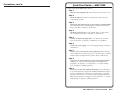
Quick Start Guide — MKP 3000
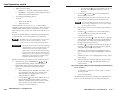
Install and set up the MKP 3000 as follows:
Step 1
Turn all of the equipment off or disconnect it from its power source.
Step 2
Install the cables that will run to and from the control panel in a
wall, podium, or desk.
Step 3
Prepare the wall, podium, desk, or other surface to mount the MKP.
See “Preparing the site and installing the mounting bracket (mud
ring) or wall box” in chapter 2, “Installation.”
Step 4
Install the control panel in a wall, podium, desk, or other surface.
See “Installation Procedures” in chapter 2, “Installation.”
Step 5
Connect the input and output cables. See “Rear Panel and Side
Panel Connections” in chapter 2, “Installation,” for guidelines.
Step 6
Connect the power supply. See “Power supply wiring” in chapter 2,
“Installation.”
Step 7
Connect power cords and turn on the equipment in the following
order: output devices (such as projectors or monitors), the connected
matrix switcher, and input devices (such as DSSs or cable boxes).
Step 8
If necessary, set the IP parameters of the control panel and matrix
switcher. See “Viewing and configuring the IP and MKP setup
parameters” in chapter 3, “Local Operation;” or “System Settings
page” in chapter 5, “HTML Operation.”
Step 9
If necessary, set the control panel’s RS-232 port for pass-through or
no-pass-through mode, and specify whether the MKP is the primary
device (connected to the switcher) or secondary device (connected
through another device). See “Viewing and configuring the IP and
MKP setup parameters” in chapter 3, “Local Operation,” or “System
Settings page” in chapter 5, “HTML Operation.”
MKP 3000 Series • Quick Start Guide
QS-1
Quick Start Guide — MKP 3000, cont’d
Step 10
Program the control panel with the size of the connected switcher.
See “System Settings page” in chapter 5, “HTML Operation.”
Step 11
Use the control panel to select inputs and outputs. See “Front Panel
Operations” in chapter 3, “Local Operation.”
Table of Contents
Chapter 1 • Introduction .......................................................... 1-1
About this Manual ................................................................ 1-2
About the MKP 3000 Series Remote Control
Panels ........................................................................................... 1-2
Setup examples ...................................................................... 1-3
RS-232 connection to the switcher ....................................... 1-4
Ethernet connection to the switcher ................................... 1-4
Application diagram .............................................................. 1-4
Chapter 2 • Installation ............................................................. 2-1
MKP Installation Overview ............................................... 2-2
Installation Procedures ....................................................... 2-3
Preparing the site .................................................................. 2-3
UL requirements for wall box installation ........................... 2-4
Installing a mounting bracket (mud ring) or wall box ........ 2-4
Mounting the MKP to a mud ring or wall box .................... 2-7
Mounting the MKP 3000 L .................................................... 2-8
Mounting the MKP 3000 L in a lectern .......................... 2-8
Mounting the MKP 3000 L in a rack ............................... 2-8
UL requirements for rack mounting ............................... 2-9
Rear Panel and Side Panel Connections .................. 2-10
Control connections ............................................................ 2-13
RS-232 connection ......................................................... 2-13
RS-232 cable termination .............................................. 2-14
Ethernet connection ...................................................... 2-15
Ethernet (TP) cable termination ................................... 2-16
Power supply wiring ............................................................ 2-18
Mounting the MKP 10 MAAP ......................................... 2-19
Chapter 3 • Local Operation .................................................. 3-1
Front Panel Controls and Indications ......................... 3-2
Front Panel Operations ....................................................... 3-4
Changing the tie mode ......................................................... 3-4
Creating ties ........................................................................... 3-5
Creating a tie in matrix mode (default) ......................... 3-5
Creating a tie in input-only mode .................................. 3-7
Deselecting a tie .............................................................. 3-8
Viewing ties ........................................................................... 3-9
Selecting a preset ................................................................ 3-10
Adjusting the audio output ................................................ 3-10
QS-2
MKP 3000 Series • Quick Start Guide
MKP 3000 Series • Table of Contents
i
Table of Contents, cont’d
Viewing and configuring the IP and MKP setup
parameters ........................................................................... 3-11
Host control port setting and pass-through
communications ............................................................. 3-13
Setting the LCD window backlighting ............................... 3-14
Setup procedures diagram .................................................. 3-14
Control panel security lockout (executive mode) .............. 3-16
Resets from the Rear Panel ............................................ 3-17
Performing soft resets ......................................................... 3-17
Performing a hard reset ...................................................... 3-19
MKP 10 MAAP and MKP 3000 L Keypad
Operation ................................................................................. 3-20
Chapter 4 • SIS™ Operation ..................................................... 4-1
RS-232 Links .............................................................................. 4-2
Routing matrix switcher commands ..................................... 4-2
Ethernet Link ........................................................................... 4-2
Default IP address .................................................................. 4-3
Host-to-MKP Instructions .................................................. 4-3
MKP-Initiated (Unsolicited) Messages ........................ 4-3
MKP Error Responses ........................................................... 4-4
Using the Command/Response Table .......................... 4-5
Symbol definitions ................................................................. 4-6
Command/Response table for MKP SIS commands ............. 4-9
Chapter 5 • HTML Operation .................................................. 5-1
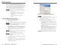
Downloading the Startup Page ..................................... 5-2
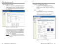
Viewing System Status ....................................................... 5-4
Using the Configuration Pages ...................................... 5-5
System Settings page ............................................................. 5-5
IP Settings section ............................................................ 5-6
Unit Name field .......................................................... 5-6
DHCP radio buttons ................................................... 5-6
IP Address field ........................................................... 5-6
Gateway IP Address field ........................................... 5-6
Subnet Mask field ...................................................... 5-7
MAC Address field ..................................................... 5-7
Firmware field ............................................................ 5-7
Model field ................................................................. 5-7
Part Number field ...................................................... 5-7
ii
MKP 3000 Series • Table of Contents
Switcher Control Settings section ................................... 5-7
MKP Connection Priority settings ............................. 5-7
Host Control Port settings ......................................... 5-8
Switcher Size settings ................................................ 5-8
Switcher IP settings/Primary MKP settings ............... 5-8
Authorized Inputs and Authorized Outputs
settings ....................................................................... 5-9
Front Panel Configuration Lock settings .................. 5-9
Switching method radio buttons .............................. 5-9
Save/restore configuration buttons .......................... 5-9
Date/Time Settings fields ............................................... 5-10
Port (RS-232) Settings page ................................................. 5-11
Passwords page .................................................................... 5-12
Assigning a password .................................................... 5-12
Clearing a password ...................................................... 5-13
Input/Output Names page .................................................. 5-13
Preset Names page .............................................................. 5-14
Firmware Upgrade page ..................................................... 5-16
Updating the firmware using a direct computer-toMKP connection ............................................................. 5-18
Using the File Management Page ............................... 5-20
Uploading files ..................................................................... 5-20
Adding a directory ............................................................... 5-21
Other file management activities ....................................... 5-21
Saving and Restoring a Configuration .................... 5-21
Saving a configuration ........................................................ 5-21
Restoring a configuration ................................................... 5-23
Special Characters ............................................................... 5-24
Appendix A • Reference Information ............................ A-1
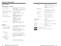
Specifications ......................................................................... A-2
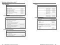
Part Numbers .......................................................................... A-4
Included parts ....................................................................... A-4
Installation accessories ......................................................... A-4
Cables .................................................................................... A-5
Optional accessories ............................................................. A-5
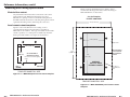
Mounting and Cabling Specifications ....................... A-6
Electrical box cutout ............................................................. A-6
Panel mount cutout templates ............................................ A-6
Extron Comm-Link Control System cable ............................ A-9
Changing Button Labels .................................................... A-9
MKP 3000 Series • Table of Contents
iiii
Table of Contents, cont’d
MKP 3000 Series
1
Chapter One
Introduction
About this Manual
About the MKP 3000 Series Remote Control Panels
All trademarks mentioned in this manual are the properties of their respective owners.
68-1069-01 C
04 07
ii
iv
MKP 3000 Series • Table of Contents
Introduction
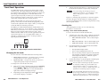
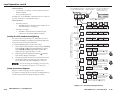
Setup examples
About this Manual
The matrix switcher system can have up to 128 inputs and 128
outputs. However, for example, a conference room may have
three input devices and two output devices, a training room
next door may have four input devices and one output device,
and so on. Typically, each room has one or more MKP control
panels assigned to it, with each MKP limited to the inputs and
outputs that it can control.
This manual provides installation and operation instructions for
the Extron MKP 3000, MKP 3000 L, and MKP 3000 MAAP
Remote Control Panels.
The MKP 3000 Series are network-ready remote control panels
that can control any Extron matrix switcher. The MKPs’ RS-232
ports allow them to communicate with other devices (another
MKP or a matrix switcher) locally and their Ethernet port allows
them to communicate with multiple devices.
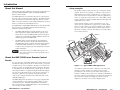
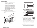
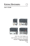
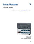
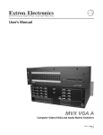
In the example in figure 1-1, the “presentation room” (top,
center) has one output device, a projector (C), and four input
devices: a video camera (13), a laptop computer (12), and two
PCs (11 and 14). The “Media Room” (bottom, right) contains
the matrix switcher, as well as other inputs (1-6) and possibly
some control device(s).
The MKP 3000 L and the MKP 3000 MAAP are each functionally
the same device as the MKP 3000, but with the following
differences in their front panels:
•
•
The MKP 3000 MAAP front panel includes a four-space
mini architectural adapter plate (MAAP) opening. Any
MAAP device can be installed in this space; but a typical
application would include an MKP 10 MAAP, which is an
auxiliary keypad for the MKP 3000.
The MKP 3000 L model is designed to be installed in a
lectern. Its front panel is shorter and wider than that of
the MKP 3000, and has a built-in 12-button keypad similar
to the Extron MKP 10 MAAP. You can also install this
model in a rack, using the optional UCM RAAP controller
rack mounting kit.
In this manual, the term “MKP 3000” applies to all
three models unless the description specifically names a
particular model.
Input
13
C
Training
Room
Input
7-9
Input
10
12
A
D
Media
Room
B
Extron
Electro
P
la
ye
V r
P CR 1
la
ye
D r
P VD 2
la
ye
V r
C 3
D R
S
La S
D
ev
se
R
E
ic
r
D
e
C
on
G
R
CO
trol
E
M
E
le
N
PA
r
CO
Q
PC
B
M
LU
PA
CO
E
Q
HO
M
PC
RIZ
PA
Q
O
NTA
PC
VE
L
Syn
RTI
c
CA
L
Syn
AU
c
DIO
nics
About the MKP 3000 Series Remote Control
Panels
You can create ties on the MKP 3000 in two modes: matrix mode
(the default) and input-only mode. In matrix mode, you specify
an input and one or more outputs to be tied to it. In input-only
mode, you select one output, then specify an input to be tied to
it. The MKP can also be dedicated to a specific group of inputs
and outputs when it is configured using the built-in Web pages.
You can also recall global presets, view current connections, or
adjust the volume for any output by using the front panel
controls, SIS™ (Simple Instruction Set) commands, and/or the
embedded Web pages.
The MKP 3000 panel is mounted on a two-gang wall plate that
can be installed in a wall, conference table, podium, or other
convenient location. The MKP 3000 MAAP is mounted in a
three-gang wall plate, and the MKP 3000 L is mounted directly
onto a lectern or other furniture.
1-2
MKP 3000 Series • Introduction
Input
14
Input
11
Video Conference
Room
Presentation
Room
Input
1-6
I/O
SELECT
Extron
MKP 3000
MKP 3000
Keypad
Figure 1-1 — Typical MKP 3000 applications
An overflow crowd in the video conference room and/or the
training room may need to see a lecture going on in the
presentation room. In this case, the video camera (input 13)
must be available to those other rooms. Therefore, the MKPs in
the video conference and training rooms will be programmed to
allow selection of input 13 for displays in those rooms, in
addition to any video sources and/or displays there.
MKP 3000 Series • Introduction
1-3
Introduction
RS-232 connection to the switcher
Any number of MKP 3000s can be connected to a matrix
switcher through its RS-232 port, but one MKP must be
designated as the primary controller. Other MKPs can be daisy
chained through the primary MKP remote control panel.
Ethernet connection to the switcher
Any number of MKP 3000s can be connected to a matrix
switcher as part of an Ethernet local area network (LAN).
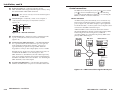
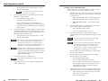
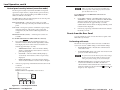
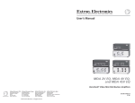
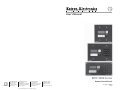
Application diagram
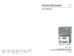
Figure 1-2, below, shows an example of how multiple
MKP 3000s can be connected to a matrix switcher.
Extron
MKP 10 MAAP
2
1
6
5
4
I/ O
9
8
7
NC
CA
I/O
I
N
P
Accessory 10-Key
Keypad
3
I
N
P
EL
0
1
CK
BA
MK
P 10
17
CT
LE
SE
PO
RE WER
SE
T
MK
0
P3
M
00
AA
2
18
P
1
17
2
18
3
19
3
19
4
20
4
20
5
21
5
21
6
22
6
22
7
23
7
23
8
24
8
24
9
25
9
25
10
26
10
26
11
27
11
27
12 U
T
S
28
12
28
13
29
13
29
14
30
14
30
15
31
15
31
16 U
T
S
L
TRO
CON
32
16
32
O
U
T
P
U
T
S
LY
PP
SU
R
RY
WE
PO PRIMA T
AN
ND
DU
RE
SW
ITC
HER
IES
0 SER
320
MAV
Matrix Switcher
Switcher
RS-232 Port
Extron
MKP 3000 MAAP
Ethernet
Ethernet
X-Y Remote Control
Panel w/ LCD Display
and MAAP Openings
I/ O
PO
RE WER
SE
T
CT
LE
SE
00
P 30
MK
MKP 3000
Host
RS-232 Port
CT
LE
SE
PO
RE WER
SE
T
00
P 30
MK
MKP 3000
2
Chapter Two
Installation
MKP Installation Overview
I/ O
I/ O
PO
RE WER
SE
T
X-Y Remote Control
Panel w/ LCD Display
MKP 3000 Series
CT
LE
SE
P 30
MK
00
MKP 3000
Control
System
Installation Procedures
Rear Panel and Side Panel Connections
Figure 1-2 — MKP 3000 application diagram
Mounting the MKP 10 MAAP
1-4
MKP 3000 Series • Introduction
Installation
CAUTION
Installation and service must be performed by
authorized personnel only. Extron recommends
that only UL listed electrical boxes be used. See
“UL Requirements for Wall Box Installation,” on
the next page.
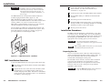
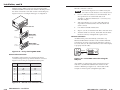
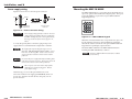
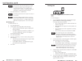
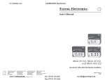
The MKP 3000 remote control panel should be installed in a
standard, 2-gang electrical wall box (figure 2-1). The
MKP 3000 MAAP should be installed in a 3-gang wall box.
Figure 2-1 shows the MKP installed in a wall. This could also be in
a desk, a podium, or any other convenient location. The
MKP 3000 L can be installed in a lectern or in a rack using the
optional UCM RAAP controller rack mounting kit.
The procedures provided here assume that the electrical wall
boxes and the cables have been installed for the system. “Rear
Panel and Side Panel Connections,” starting on page 2-10,
provides guidance for terminating the cables.
3
Connect the cable between the MKP and the
matrix switcher. See “Rear Panel and Side Panel
Connections,” on page 2-10.
4
Connect power cords to the MKP and the matrix switcher.
5
Test the MKP’s ability to communicate with the matrix
switcher.
6
Disconnect power from all the devices.
7
Mount the MKP into the electrical box or to the mud ring.
If using a wall box, see “Mounting the MKP to a mounting
mud ring or wall box,” later in this chapter.
8
Restore power to the devices.
Installation Procedures
The MKPs can be mounted into a wall, furniture, or any other
convenient location. The MKP 3000 L can also be installed in a
rack, using the optional UCM RAAP Universal Controller Rack
Mounting Kit, part #70-344-02, -03). Follow the instructions
appropriate to the mounting option you have selected.
CAUTION
When installing MKP control panels, you must conform
to all national and local electrical codes.
I/ O
CT
LE
SE
PO
W
RE ER
SE
T
MK
Ex
tro
0
00
P3
n
Figure 2-1 — MKP mounted in a wall box
MKP Installation Overview
To install an MKP 3000 remote control panel, follow these steps:
2-2
The control panel must be installed into a
Underwriters Laboratories (UL) approved electrical
wall box.
1
Disconnect power from the matrix switcher and all MKPs
in the system.
2
Prepare the site: cut a hole in the wall or furniture, install
the electrical box or mounting bracket (“mud ring”) if
needed, and prepare the cables. Instructions are included
in this manual and/or with the wall box. See “Installation
Procedures,” on the next page.
MKP 3000 Series • Installation
Preparing the site
Choose a location that allows cable runs without interference.
Allow enough depth for both the wall box and the cables. You
may need to install the cables into the wall, furniture, or
conduits before installing the control panel.
The installation must conform to national and local electrical
codes and to the equipment’s size requirements. Cutout
templates that show the cut-out requirement for the circuitry
enclosure on the rear of the control panel are provided in
appendix A of this manual.
CAUTION
Only the MKP 3000 template in this manual is to
scale. Use the others for reference only.
MKP 3000 Series • Installation
2-3
Installation, cont’d
UL requirements for wall box installation
4.
Check the opening size by inserting the wall box, mud
ring, or control panel into the opening. The box or mud
ring and/or control panel should fit easily into the
opening. Enlarge or smooth the edges of the opening if
needed.
5.
If you are using a wall box, feed the cables through the
wall box punch-out holes, and secure them with cable
clamps to provide strain relief.
6.
Exposed cable shields (braids or foil) are potential sources
of short circuits. Trim back and/or insulate shields with
heat shrink (figure 2-2).
The following UL requirements pertain to the installation of the
MKP 3000 into a wall (figure 2-1) or furniture.
1.
These units are not to be connected to a centralized DC
power source or used beyond their rated voltage range.
2.
These units must be installed in UL listed junction boxes.
3.
These units must be installed with conduit in accordance
with the National Electrical Code.
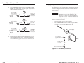
Installing a mounting bracket (mud ring) or wall
box
Extron recommends using a UL listed wall box (available from
Extron) for most mounting options, but you can use the
included mounting brackets (mud rings) instead.
Wall Stud
Before using the mud rings, verify that the installation
conforms to national and local electrical codes.
Screws or Nails
The electrical box must be at least 2.5" (7 cm) deep to
accommodate the MKP’s rear enclosure.
Cable
Clamp
Install the mud ring or wall box as follows:
1.
If you are using a mud ring, use the template that came
with the mud ring. Cut out the indicated center portion.
To meet the UL listing requirements, the MKP must be
installed in a wall box.
Foil
Shield
Installation
Cable
If you are using a wall box, refer to the cut-out template
in appendix A that corresponds to the faceplate you are
using, and cut out the center portion of it as indicated on
the template.
Braided
Shield
Screw
Figure 2-2 — Grounding braided and foil shields
CAUTION
2-4
Extron provides one mud ring with each MKP
control panel. However, the user may choose to use
a wall box. Because the tolerances on electrical
boxes are very loose, Extron recommends that you
measure the actual box that you plan to use before
making any precise cuts.
2.
Use the template (or place the wall box or mud ring
against the installation surface), and mark the guidelines
for the opening on the wall or furniture.
3.
Cut out the wall material from the marked area.
MKP 3000 Series • Installation
To prevent short circuits, the outer foil shield can be
cut back to the point where the cable exits the cable
clamp. Both braided and foil shields should be
connected to an equipment ground at the other end
of the cable.
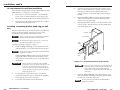
7.
If you are using a mud ring, follow the directions, if any,
that came with the mud ring to attach the clips that fasten
it to the wall or furniture (figure 2-3).
To meet UL listing requirements, the MKP must be
installed in a wall box.
MKP 3000 Series • Installation
2-5
Installation, cont’d
Wall Stud
Sheet Rock
Backing Clip
Wall Box
0.75" #6-32 Screw
Mounting Bracket
Detail A
Sheet Rock
Backing Clip
1.25" #6-32 Screw
Mounting Bracket
I/ O
Detail B
CT
LE
SE
PO
W
RE ER
SE
T
Backing clip can
be in either orientation.
See Detail A or Detail B.
P3
Screws or Nails
0
00
MK
Extron
MKP 3000
Figure 2-4 — Attaching a wall box to a wall stud
Ex
tro
n
8.
Figure 2-3 — Attaching a mud ring to a wall
If you are using a wall box, insert the wall box into the
opening, and attach it to the wall stud or furniture with
nails or screws, leaving the front edge flush with the outer
wall or furniture surface (figure 2-4).
If attaching the wall box to wood, use four #8 or #10
screws or 10-penny nails. A minimum of ½ inch (1.3 cm)
of screw threads must penetrate the wood.
MKP 3000 Series • Installation
Connect the Ethernet and/or RS-232 cable (as appropriate)
and the power cable, and test the MKP before fastening the
MKP into the wall box. See “Rear Panel and Side Panel
Connections,” on page 2-10, for details.
The rear panel connectors are inaccessible after
installation.
Mounting the MKP to a mud ring or wall box
If the installation involves an MKP 3000 MAAP and an
optional MKP 10 MAAP remote keypad, mount the
MKP 10 MAAP to the MKP 3000 MAAP before
installing the MKP 3000 MAAP into the mud ring or
wall box. See “Mounting the MKP 10 MAAP,” on
page 2-19.
If attaching the wall box to metal studs or furniture, use
four #8 or #10 self-tapping sheet metal screws or machine
bolts with matching nuts.
2-6
Flush with
Wall Surface
1.
Remove power from the control panel by disconnecting
the power supply.
2.
Place the control panel through the opening in the wall or
furniture and through the mud ring or into the wall box.
Take care not to damage the cables, which fit behind the
MKP, at the back of the wall box.
MKP 3000 Series • Installation
2-7
Installation, cont’d
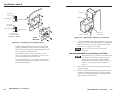
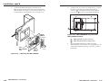
3.
Mount the MKP’s faceplate to the mud ring or wall box
with machine screws (figure 2-5).
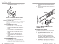
2.
Cable the MKP and any AAPs within the UCM panel (see
“Rear Panel and Side Panel Connections,” later in this
chapter).
3.
Align the UCM panel in the rack, and secure it using the
remaining screws.
Extron
UCM-RAAP
I/ O
CT
LE
SE
PO
W
RE ER
SE
T
0
00
P3
MK
Ex
tro
n
Figure 2-5 — Mounting the MKP to the wall box
4.
Extron
MKP 3000 L
Reconnect the power supply and restore power.
3
2
Mounting the MKP 3000 L
1
6
5
4
9
8
I/ O
EL
NC
7
ENO
EE
VID
GR
DIO
AURED
You can mount the MKP 3000 L in a lectern or other furniture, or
you can mount it in a rack using the UCM RAAP controller
mounting kit.
SE
PO
W
RE ER
SE
T
LE
CT
CA
0
CK
BA
0L
00
P3
MK
KE
TA
TP
OU
INP
E
Mounting the MKP 3000 L in a lectern
UT
UT
on
xtr
To mount the MKP 3000 L in a lectern or other furniture,
1.
Using the MKP 3000 L cut-out template in appendix A,
measure and mark guidelines for the opening in the
furniture.
2.
Cut out the furniture material from the marked area.
3.
Check the opening size by inserting the MKP into it.
Enlarge and/or smooth the edges of the opening as
needed.
4.
Complete all necessary cabling, and, with power
disconnected at the source, insert the MKP into the
opening.
5.
Fasten the MKP directly to the furniture using four #8 or
#10 screws or 10-penny nails.
Figure 2-6 — Mounting the MKP 3000 L to the
UCM RAAP and a rack
UL requirements for rack mounting
The following Underwriters Laboratories (UL) requirements
pertain to the installation of the MKP 3000 L into a rack.
1.
Elevated operating ambient temperature — If the
equipment is installed in a closed or multiunit rack
assembly, the operating ambient temperature of the rack
environment may be greater than room ambient.
Therefore, consider installing the equipment in an
environment compatible with the maximum ambient
temperature (Tma) specified by the manufacturer. For the
MKP 3000, the Tma is 122 °F (50 °C).
2.
Reduced air flow — Installation of the equipment in a
rack should be such that the amount of air flow required
for safe operation of the equipment is not compromised.
Mounting the MKP 3000 L in a rack
To mount the MKP 3000 L in a rack using the UCM RAAP,
1.
2-8
Attach the MKP 3000 L to the UCM RAAP using the four
flat Philips head machine screws provided with the UCM.
MKP 3000 Series • Installation
MKP 3000 Series • Installation
2-9
Installation, cont’d
3.
Mechanical loading — Mounting of the equipment in the
rack should be such that a hazardous condition is not
achieved due to uneven mechanical loading.
4.
Circuit overloading — Consideration should be given to
the connection of the equipment to the supply circuit and
the effect that overloading of the circuits might have on
overcurrent protection and supply wiring. Appropriate
consideration of equipment nameplate ratings should be
used when addressing this concern.
1
2
3
6
4
5
Reliable earthing (grounding) — Reliable earthing of
rack-mounted equipment should be maintained.
Particular attention should be given to supply connections
other than direct connections to the branch circuit (for
example, use of power strips).
5.
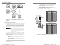
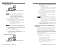
Figure 2-8 — MKP 3000 MAAP rear panel
Rear Panel and Side Panel Connections
1
All connectors are on the rear or side of the MKP (figure 2-7, 2-8,
and 2-9). These connectors are inaccessible once the MKP is
installed.
2
3
7
4
5
Figure 2-9 — MKP 3000 L rear panel
1
1
POWER
.5A MAX
12 V
GND
2
HOST
RS-232
SWITCH
RS-232
5
SWITCH
RS-232
HOST
RS-232
Rx
REMOTE
KEYPAD
REMOTE
KEYPAD
4
Tx
GND
GN
D
3
Tx
Rx
GND
PO
.5A WER
MA
X
12
V
Tx
Rx
GN
D
2
MKP 3000 Series • Installation
Activity
LED
Link
LED
RJ-45
Port
Ethernet connection indicators — The Link and Activity LEDs
on the LAN port indicate the status of the Ethernet connection.
The green Link LED indicates that the MKP is properly
connected to an Ethernet LAN. This LED should light steadily.
The yellow Activity LED indicates transmission of data packets
on the RJ-45 connector. This LED should flicker as the MKP
communicates.
Tx
Rx
GN
D
Figure 2-7 — MKP 3000 rear and side panels
2-10
LAN (Ethernet) port — If desired, connect a
Category (CAT) 5e or higher (network) cable
between this connector and either the matrix
switcher to be controlled or to an Ethernet
local area network (LAN). See “Ethernet cable
termination,” later in this chapter, to properly
wire the RJ-45 connector for your application.
Power connector — Connect the included external 12 VDC
power supply to this 2-pole direct insertion connector. See
“Power supply wiring,” on page 2-18, to wire the connector.
MKP 3000 Series • Installation
2-11
Installation, cont’d
3
Remote Keypad port — If desired, plug the optional
MKP 10 MAAP remote keypad into this 10-pin connector, using
the cable included with the MKP 10 MAAP.
This connector is always used on the standard keypad on
an MKP 3000 L.
4
Host RS-232 port — If desired, connect a host computer or
control system to this 3-pole, 3.5 mm, RS-232 connector
(figure 2-10).
HOST
RS-232
Tx
Rx
GND
Tx
SWITCH
RS-232
Rx
GND
Pin
TX
RX
Gnd
Function
Transmit data
Receive data
Signal ground
Figure 2-10 — RS-232 connector
5
Switch RS-232 port — If desired, connect a cable between this
3-pole, 3.5 mm, RS-232 connector and a matrix switcher
(figure 2-10).
Control connections
The MKP has two RS-232 ports (a Host port [ 4 ] and a Switch
port [ 5 ]) and an LAN (Ethernet) port ( 1 ). The following
paragraphs describe different possible ways of connecting the
MKP to a switcher via RS-232 or Ethernet.
RS-232 connection
An MKP control panel can be directly cross-connected to any
Extron matrix switcher through the switcher’s switch RS-232
port (see figure 2-16, later in this chapter, for pin assignments
for the RS-232 cable). A control system or host computer can be
connected via the MKP’s Host RS-232 port.
Additional MKPs can be connected to the matrix switcher
through the MKP that is RS-232 connected (the primary MKP).
In the configuration shown in figure 2-11, additional
(secondary) MKPs are connected to the primary MKP via the
primary MKP’s Ethernet port.
MKP 3000
MKP 3000
Matrix Switcher
1
I/O
6
MAAP Opening (MKP 3000 MAAP) — The MKP 3000 MAAP
has a space that allows the installation of up to four optional
mini architectural adapter plates (MAAPs). This space is
typically filled by an optional four space MKP 10 MAAP
keypad, but a variety of other adapter plates are also available.
2
3
4
5
6
7
8
9 10 11 12
I/O
13 14 15 16 17 18 19 20 21 22 23 24
I
N
P
U
T
S
CONTROL
I/O
SELECT
SELECT
1
2
3
4
5
6
7
8
9 10 11 12
13 14 15 16 17 18 19 20 21 22 23 24
O
U
T
P
U
T
S
MAV 2400 SERIES SWITCHER
Extron
MKP 3000
Extron
MKP 3000
Switcher
RS-232 Port
MKP 3000
I/O
Blank plates (two single-space and one double-space plate) are
included with the MKP to cover unused spaces. The
MKP 10 MAAP or other MAAP(s) must be ordered separately.
They also should be attached to the faceplate and cabled before
the MKP is installed in the wall or furniture. See “Mounting the
MKP 10 MAAP,” later in this chapter.
VOLUME
I/O
SELECT
Ethernet
Ethernet
Extron
MKP 3000
MKP 3000
MKP 3000
Host
RS-232 Port
I/O
7
Keypad board (MKP 3000 L) — The 12-button keypad that is
built into the MKP 3000 L rear panel is connected to this board.
SELECT
Extron
MKP 3000
MKP 3000
Control
System
Figure 2-11 — MKP connection using the RS-232 port
2-12
MKP 3000 Series • Installation
MKP 3000 Series • Installation
2-13
Installation, cont’d
Multiple primary MKPs can also be daisy-chained together,
with the first MKP connected to the switcher’s RS-232 port and
the others connected to each other via their own RS-232 ports.
Figure 2-12 shows an example of this type of configuration.
I/O
I
N
P
I
N
P
1
17
1
17
2
18
2
18
3
19
3
19
4
20
4
20
5
21
5
21
6
22
6
22
7
23
7
23
10
9
8
24
9
8
24
26
25
10
25
26
11
27
11
27
12 U
T
S
28
13
29
14
30
15
31
16 U
OL
NTR
CO
T
S
32
LY
PP
SU
R
RY
WE
PO PRIMA T
AN
ND
DU
RE
R
O
U
T
12
28
13
29
14
30
15
31
SW
T
S
Tx
3
Rx
2
1
6
5
4
EL
NC
CA
7
0
CK
BA
10
MKP
CT
LE
SE
PO
RE WER
SE
T
AP
00
P 30
MA
MK
Primary/Passthrough
on
xtr
Rx
Tx
MKP 3000 L
3
2
1
6
5
4
9
8
I/ O
EL
NC
CA
7
O
DE
EN
VIGRE
O
DI
AURED
CT
LE
SE
PO
W
RE ER
SE
T
TA
TP
OU
INPU
Ex
Trim approximately 1.5" (3.8 cm) of the cable jacket to
expose the four insulated wires and a bare drain wire
(silver-colored).
3.
Cut off the foil shield and discard it.
4.
Strip ¼" ( 0.6 cm) of insulation from three of the four wires.
5.
Twist the strands of each wire, insert them into the direct
insertion connector, and tighten the captive screws.
MKP 3000
Tx
Rx
Switcher
RS-232 Port
2.
9
8
I/O
E
Choose a cable such as Extron’s Comm-Link cable. The
wire specifications for Comm-Link cable are in
appendix A, “Reference Information.” Colors may vary
from this example.
Matrix Switcher
Tx
Host
RS-232 Port
1.
HE
ITC
Rx
Switcher
RS-232 Port
The total cable length between an MKP control panel
and a matrix switcher should not exceed 100 feet (30 m).
IES
0 SER
V 320
MA
16 UP
32
Wire the connectors as follows:
0
CK
BA
MK
P 30
00
L
Primary/MKP 3000
Ethernet connection
An MKP control panel can be directly connected to any
Ethernet-enabled matrix switcher via the switcher’s Ethernet
port (figure 2-13) using a TP (network) cable that is wired as a
crossover cable (see “TP cable termination,” later in this chapter,
to properly wire the cable).
KE
UT
T
n
tro
1
I/O
LAN Port
Figure 2-12 — Daisy-chaining MKP 3000s
Pin
Switcher RS-232
1
2
3
4
5
6
7
8
9
–
Tx
Rx
–
Gnd
–
–
–
–
MKP 3000
MKP 3000
Each MKP control panel has two RS-232 ports that are
connected using 3.5 mm, 3-pole direct insertion connectors.
Figure 2-13 shows the pin assignments for these ports.
MKP RS-232
–
Rx
Tx
–
Gnd
–
–
–
–
3
4
5
6
7
8
9 10 11 12
Crossover
Cable
I
N
P
U
T
S
I/O
CONTROL
1
Extron
RS-232 cable termination
2
13 14 15 16 17 18 19 20 21 22 23 24
SELECT
2
3
4
5
6
7
8
9 10 11 12
13 14 15 16 17 18 19 20 21 22 23 24
O
U
T
P
U
T
S
MAV 2400 SERIES SWITCHER
Matrix Switcher
Figure 2-14 — Direct MKP connection using the
LAN port
Any number of control panels can be connected as part of a
network to any Ethernet-enabled matrix switcher via the
switcher’s Ethernet port (figure 2-14). All TP cables in this
example are wired as patch (straight-through) cables.
Figure 2-13 — RS-232 cross-connection table
2-14
MKP 3000 Series • Installation
MKP 3000 Series • Installation
2-15
Installation, cont’d
MKP 3000
MKP 3000
Matrix Switcher
1
I/O
2
3
4
5
6
7
8
9 10 11 12
I/O
13 14 15 16 17 18 19 20 21 22 23 24
•
Crossover cable — Direct connection between the MKP
and a host computer or an Ethernet-enabled matrix
switcher (figure 2-14)
•
Patch (straight) cable — Network connection between
the MKP and an Ethernet LAN (figure 2-14)
I
N
P
U
T
S
CONTROL
I/O
SELECT
SELECT
1
2
3
4
5
6
7
8
9 10 11 12
13 14 15 16 17 18 19 20 21 22 23 24
O
U
T
P
U
T
S
MAV 2400 SERIES SWITCHER
Extron
MKP 3000
Extron
MKP 3000
For pin assignments, see figure 2-16, below.
MKP 3000
Patch (straight) cable
I/O
SELECT
Extron
Ethernet
RS-232
Pin
Side 1
Wire color
Pin
Side 2
Wire color
MKP 3000
I/O
Side
SELECT
Extron
Clip Down
12345678
RJ-45
connector
MKP 3000
MKP 3000
Pins
Control
System
Figure 2-15 — Network MKP connection using the
LAN port
Twisted
Pairs
7&8
1&2
Do not stretch or bend cables. This can cause
transmission errors.
The cable you use depends on your network speed. The MKP
supports both 10 Mbps (10Base-T — Ethernet) and 100 Mbps
(100Base-T — Fast Ethernet), half-duplex and full-duplex,
Ethernet connections.
•
10Base-T Ethernet requires CAT 5 UTP or STP cable as a
minimum
•
100Base-T Fast Ethernet requires CAT 5e UTP or STP
cable as a minimum
3 White-green
3 White-green
4 Blue
4 Blue
5 White-blue
5 White-blue
6 Green
6 Green
7 White-brown
7 White-brown
8 Brown
8 Brown
Crossover cable
It is vital that you use the correct Ethernet cables, and that they
be properly terminated with the correct pinout. Ethernet links
use Category (CAT) 5, 5e or CAT 6, unshielded twisted pair
(UTP) or shielded twisted pair (STP) cables, terminated with
RJ-45 connectors. Ethernet cables are limited to 328' (100 m).
Do not use standard telephone cables. Telephone
cables do not support Ethernet or Fast Ethernet.
1 White-orange
2 Orange
12345678
Ethernet (TP) cable termination
CAUTION
1 White-orange
2 Orange
3&6 4&5
Pin
Side 1
Wire color
Pin
Side 2
Wire color
1 White-orange
1 White-green
2 Orange
2 Green
3 White-green
3 White-orange
4 Blue
4 Blue
5 White-blue
5 White-blue
6 Green
6 Orange
7 White-brown
7 White-brown
8 Brown
8 Brown
Figure 2-16 — RJ-45 connector and pinout tables
The Ethernet cable can be terminated as a straight-through cable
or a crossover cable. It must be terminated properly for your
application (figure 2-16).
2-16
MKP 3000 Series • Installation
MKP 3000 Series • Installation
2-17
Installation, cont’d
Power supply wiring
Mounting the MKP 10 MAAP
Figure 2-17 shows how to wire the power connector.
Smooth
Ridges
A
12 V
GND
A
The MKP 3000 MAAP has a space that allows the installation of
up to four optional mini architectural adapter plates. This space
is typically filled by an optional four space MKP 10 MAAP
keypad (figure 2-18).
SECTION A–A
Power Supply
Output Cord
Direct Insertion
Connector
Figure 2-17 — Power connector wiring
CAUTION
Power supply voltage polarity is critical. Incorrect
voltage polarity can damage the power supply and
the MKP. Identify the power cord negative lead by
the ridges on the side of the cord (see figure 2-17,
above).
To verify the polarity before connection, plug in the power
supply with no load and check the output with a voltmeter.
The length of the exposed (stripped) copper wires is
important. The ideal length is 3/16" (5 mm). Longer
bare wires can short together. Shorter wires are not as
secure in the direct insertion connectors and could be
pulled out.
1
2
3
4
5
6
7
8
9
BACK
0
CANCEL
MKP 10
Figure 2-18 — MKP 10 MAAP keypad
When the connected switcher has a large matrix size (up to 128
by 128) selecting an input or output number by rotating the
Select knob can be inconvenient. The optional MKP 10 MAAP
keypad allows rapid input/output selection.
Mount the MKP 10 MAAP to the MKP 3000 MAAP before
installing the MKP 3000 MAAP, as follows:
The proper MKP 10 MAAP orientation is with the
power LED up.
Do not tin the power supply leads before installing them
in the direct insertion connector. Tinned wires are not as
secure in the connectors and could be pulled out.
The two power cord wires must be kept separate
while the power supply is plugged in. Remove
power before wiring.
Alternatively, you can use the optional Extron P/S 123
Universal 12 VDC Power Supply, part #60-814-01, which can
power up to 10 Extron 12 VDC devices using only one AC
power connector.
2-18
MKP 3000 Series • Installation
MKP 3000 Series • Installation
2-19
Installation, cont’d
1.
Sandwich the MKP 3000 MAAP panel between the
MKP 10 MAAP module (without its front panel) and the
MKP 10 MAAP’s front panel. Secure the front panel to the
module with the included #4-40 screws (see figure 2-19 ).
2.
See figure 2-20. If you have not already done so, connect
the serial control and power cables between the J1
connector ( 1 ) on the MKP 10 MAAP and the Remote
Keypad port ( 2 ) on the rear of the MKP 3000 MAAP.
2
1
Extron
MKP 10
Front Panel
I/ O
Figure 2-20 — MKP 3000 MAAP rear panel with
MKP 10 MAAP mounted
1
MKP 10 MAAP J1 control connector
2
MKP 3000 MAAP Remote Keypad port
3
2
1
6
5
CT
LE
SE
PO
W
RE ER
SE
T
4
0
00
P3
AP
MA
MK
9
7
CA
EL
NC
0
CK
BA
P
MK
Extron
MKP 3000 MAAP
Panel
E
on
xtr
Extron
MKP 10
3.
8
10
(4) #4-40
Screws
Mount the MKP 3000 MAAP (with the mounted
MKP 10 MAAP) to the wall box or mounting bracket. See
“Mounting the MKP to mud ring or wall box,” earlier in
this chapter.
Module
Figure 2-19 — Mounting the MKP 10 MAAP
2-20
MKP 3000 Series • Installation
MKP 3000 Series • Installation
2-21
Installation, cont’d
MKP 3000 Series
3
Chapter Three
Local Operation
Front Panel Controls and Indications
Front Panel Operations
Rear Panel Resets
MKP 10 MAAP and MKP 3000 L Keypad Operation
2-22
MKP 3000 Series • Installation
Local Operation
The labels in these buttons can be removed and replaced to
reflect the function of the button. A sheet of labels is provided
with the MKP. See “Changing Button Labels” in appendix A,
“Reference Information,” for the procedure for changing these
labels.
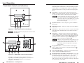
Front Panel Controls and Indications
1
I/O
VIDEO
8
GREEN
1
AUDIO
RED
The LCD display shows the most recent input, output, or
preset name and number entered from this MKP. Ties
created using other devices (other MKPs, a PC or control
system, or the matrix switcher’s front panel) are not
shown in the LCD display.
SELECT
INPUT
OUTPUT
TAKE
5
Extron
2
Input/Preset button — Selects an input or places the MKP in
preset mode.
3
Output/View button — Selects an output or places the MKP in
view mode.
4
Take button — Takes (activates) a new tie or preset. This button
is the equivalent of the Enter button on the matrix switcher’s
front panel.
5
Select knob — This knob, when rotated, scrolls through the
available inputs, outputs, or presets. It also ramps volume up
or down, depending on which of buttons 2 and 3 and which
operating mode are selected. The inputs, outputs, presets, or
volume level are shown in the LCD display ( 1 ).
MKP 3000
2
3
4
Figure 3-1 — MKP 3000 controls and indicators
The MKP 3000 MAAP front panel has the same controls
and indicators.
8
7
1
2
3
4
5
6
7
8
9
BACK
0
CANCEL
When the connected switcher has a large matrix size (up
to 128 by 128) selecting an input or output number by
rotating the Select knob can be inconvenient. An
optional MKP 10 MAAP keypad allows rapid input/
output selection.
I/O
VIDEO
GREEN
1
AUDIO
RED
6
SELECT
INPUT
OUTPUT
TAKE
Extron
2
MKP 3000 L
3
4
6
Keypad (MKP 3000 L) — Use these buttons to select inputs
and/or outputs as an alternative to using the Select knob ( 5 ),
on the MLK 3000 L only.
7
Power LED (MKP 3000 L) — When lit, this LED indicates that
power is applied to the MKP 3000 L keypad.
8
Input/Output (I/O) (video/audio) selection button — Press the
I/O button to select video and audio, video only, or audio only
for the current input and output selections. As you cycle
through the selections, the button lights amber for video and
audio, green for video only, and red for audio only. This button
also selects audio volume mode.
5
Figure 3-2 — MKP 3000 L controls and indicators
The buttons on this panel perform different functions,
depending on the MKP’s operating mode. See “Front Panel
Operations,” later in this chapter, for a more detailed
description of the modes.
3-2
LCD display — Shows the input, output, preset name and
number, or volume level during operation. In certain modes, it
can also show the IP addresses programmed into the MKP.
MKP 3000 Series • Local Operation
MKP 3000 Series • Local Operation
3-3
Local Operation, cont’d
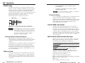
3.
Front Panel Operations
The MKP 3000 normally operates in the matrix input/output
selection mode. This is the default mode, in which you can set
up a tentative tie by selecting an input, selecting an output, and
then taking (commanding) the tie. The MKP 3000 can also
operate in input-only mode, in which you can view the current
ties by scrolling the outputs. In this mode, you first select an
output, then complete the tie by selecting an input.
Additionally, the MKP can operate in preset mode (select
presets), view mode (view ties without changing them), audio
volume mode (adjust the audio output volume), or setup mode
(set the IP addresses and other parameters).
The MKP is provided with default labels installed in the front
panel buttons (figure 3-3). It also includes a strip of alternative
labels that you can insert in one or more of the mode selection
buttons to make using the other modes more clear. These
additional button labels are shown in the applicable front panel
operation descriptions. See “Changing Button Labels” in
appendix A, “Reference Information,” for the procedure for
replacing these button labels.
Turn the Select knob clockwise or counterclockwise until
the desired mode (Matrix or Input-Only) is displayed.
You can also change the tie mode by using SIS
commands (see chapter 4, “SIS™ Operation,”) or the
Ethernet Web pages (see chapter 5, “HTML
Operation”).
Figure 3-7, “Selecting setup parameters,” later in this chapter,
provides a diagram of the procedures for setting up the IP
connection, backlight duration, and tie mode parameters using
the front panel controls.
Creating ties
After selecting the tie mode, use one of the following
procedures to create the ties.
Creating a tie in matrix mode (default)
To create a tie in matrix mode (the default mode),
1.
Select the type of tie (video, audio, or both) by repeatedly
pressing the I/O button until it lights the desired color:
•
Video and audio selected — The I/O button lights
amber.
•
Video only selected — The I/O button lights green.
•
Audio only selected — The I/O button lights red.
VIDEO
GREEN
AUDIO
RED
SELECT
INPUT
OUTPUT
2.
TAKE
Figure 3-3 — Input/output selection mode labels
Changing the tie mode
You can create ties on the MKP 3000 in the following modes:
•
Matrix mode (the default) — In matrix mode, you specify
an input and one or more outputs to be tied to it.
•
Input-only mode — In input-only mode, you select one
output, then specify an input to be tied to it.
To change from one tie mode to the other,
3-4
1.
Enter setup mode by simultaneously pressing and holding
buttons 2 , 3 , and 4 (typically labeled Input, Output,
and Take) for approximately 2 seconds until all buttons
light amber and the LCD display changes.
2.
Repeatedly press the Input button (button
LCD window displays “Tie Mode.”
MKP 3000 Series • Local Operation
2
) until the
3.
Press the Input button to specify that the next number
entered will be an input number.
•
The Input button lights amber.
•
If it was lit, the Output button turns off.
•
The most recently selected output is locked (unable
to be changed; assigned as the output to which the
entered input is tied unless a different output is
assigned [see steps 4 and 5]).
Use the Select knob to scroll through the available inputs
until the LCD display shows the desired input.
The Select knob scrolls through only those inputs that
are within the available range for this MKP or the
connected matrix switcher. See “Switcher Control
Settings section” in chapter 5, “HTML Operation,” for
information on authorizing inputs and outputs.
If an optional MKP 10 MAAP keypad is connected or
you are using an MKP 3000 L, you can use the keypad
in place of the Select knob. See “MKP 10 MAAP and
MKP 3000 L Keypad Operation,” later in this chapter.
MKP 3000 Series • Local Operation
3-5
Local Operation, cont’d
•
The LCD display shows the input that you select.
•
The Take button blinks.
The blinking Take button times out after 15
seconds if it is not pressed.
4.
5.
Creating a tie in input-only mode
In input-only mode, you select an output to which you can tie
only one input. To create a tie in input-only mode,
1.
Press the Output button to specify that the next number
entered is an output number.
•
The Output button lights amber.
•
If it was lit, the Input button goes out.
•
The last selected input is locked (unable to be
changed; assigned as the input to which the entered
output is tied unless a different input is assigned [see
steps 2 and 3]).
Use the Select knob to scroll through the available outputs
until the LCD display shows the desired output, or enter
the desired output number on the keypad (MKP 3000 L or
MKP 3000 AAP with keypad only).
•
The LCD display shows the output that you select.
•
The Take button blinks.
2.
3.
Select the type of tie (audio only, video only, or audio and
video) by repeatedly pressing the I/O button until it lights
the desired color:
•
Video only selected — The I/O button lights green.
•
Audio only selected — The I/O button lights red.
•
Video and audio selected — The I/O button lights
amber.
Press the Output button to specify that the next number
that is entered will be an output number.
•
The Output button lights amber.
•
If it was lit, the Input button turns off.
Turn the Select knob to scroll through the available
outputs until the LCD window displays the desired output
number.
As you scroll through the outputs, the LCD display
indicates whether or not the output is tied.
The Select knob scrolls through only those outputs that
are inside the available range for this MKP or the
connected matrix switcher. See “Switcher Control
Settings section” in chapter 5, “HTML Operation,” for
information on authorizing inputs and outputs.
When an input or output outside the available range for
this MKP or the connected matrix switcher is selected
using an optional MKP 10 MAAP keypad or the keypad
of the MLC 3000 L, the LCD display shows Invalid
Input or Invalid Output.
6.
7.
The Select knob scrolls through only those outputs that
are within the available range for this MKP or the
connected matrix switcher. See “Switcher Control
Settings section” in chapter 5, “HTML Operation,” for
information on authorizing inputs and outputs.
The LCD display shows the output that you selected and
its status (tied or untied).
4.
Press the Take button to confirm the tie.
The blinking Take button times out after 15 seconds if
not selected.
•
The Input button lights amber.
•
If it was lit, the Output button turns off.
Repeat steps 5 and 6 for each additional output that you
want to add to the tie.
•
The most recently selected output is locked (unable
to be changed; assigned as the output to which the
entered input is tied unless a different output is
assigned [steps 2 and 3]).
5.
3-6
Press the Input button to specify that the next number
entered will be an input number.
MKP 3000 Series • Local Operation
Turn the Select knob to scroll through the available inputs
until the LCD window shows your desired input number.
•
The LCD display shows the input that you selected
and its status (tied or untied).
•
The Take button blinks.
MKP 3000 Series • Local Operation
3-7
Local Operation, cont’d
The Select knob scrolls only through those inputs that
are within the available range for this MKP or the
connected matrix switcher. See “Switcher Control
Settings section” in chapter 5, “HTML Operation,” for
information on authorizing inputs and outputs.
6.
Viewing ties
VIDEO
GREEN
AUDIO
RED
SELECT
OUTPUT
Press the Take button to confirm the tie.
INPUT
HOLD
TAKE
VIEW
The blinking Take button times out after 15 seconds if it
is not pressed.
If an optional MKP 10 MAAP keypad is connected or
you are using an MKP 3000 L, you can use the keypad
in place of the Select knob. See “MKP 10 MAAP and
MKP 3000 L Keypad Operation,” later in this chapter.
Figure 3-4 — Suggested button labels for view
mode
To view existing ties,
1.
Deselecting a tie
To deselect (break) a tie,
1.
Press the Input button.
2.
Set the input to 0 by doing either of the following:
Press and hold the Output button until the button lights
green to indicate view mode (approximately
2 seconds), then release the button.
•
The I/O button lights green to indicate that the LCD
will show video ties.
•
The tied inputs and outputs are locked (unable to be
changed).
•
Turn the Select knob until No Signal is displayed in
the LCD window.
•
The LCD display shows the output that is currently
selected ( > ).
•
If an MKP 10 MAAP is installed in your MKP or you
are using an MKP 3000 L, press 0 on its keypad.
•
The LCD shows the last tie created from the MKP.
Ties created using other devices (other MKPs, a
computer or control system, or the matrix switcher’s
front panel) are not shown in the LCD display until the
panel is accessed or the Output button is pressed to
refresh the view.
The Take button begins to blink.
3.
Press the Output button.
4.
Select the output that you want to untie by doing either of
the following:
5.
•
Turn the Select knob until the desired output number
is displayed in the LCD window.
•
On the MKP 10 MAAP or the MKP 3000 L keypad,
press the desired output number.
2.
•
The outputs as you scroll past them
•
The input that is tied to each output as it is displayed
Press Take.
If an optional MKP 10 MAAP keypad is connected, you
can use it in place of the Select knob to select a specific
output whose tied input you want to check. See
“MKP 10 MAAP Operation,” later in this chapter.
3.
4.
3-8
Use the Select knob to scroll through the available outputs.
The LCD display shows the following:
MKP 3000 Series • Local Operation
If desired, press and release the I/O button to set the MKP
to display audio ties.
•
The I/O button lights red.
•
If desired, view the audio ties as described in step 2.
To exit view mode, press and hold the Output button until
the button lights amber to indicate I/O Selection mode
(approximately 2 seconds) .
MKP 3000 Series • Local Operation
3-9
Local Operation, cont’d
Selecting a preset
Press and hold the I/O button until it lights red to indicate
audio volume mode (approximately 2 seconds), then
release the button.
1.
VIDEO
GREEN
AUDIO
RED
SELECT
•
The output button lights.
•
The LCD display shows the selected ( > ) output and
a slide bar that shows the audio output level of the
selected output.
INPUT
OUTPUT
HOLD
TAKE
PRESET
Figure 3-5 — Suggested button labels for preset
mode
• Presets must have been created in the matrix switcher
to be valid. Refer to the user’s manual for the
connected matrix switcher to create presets.
2.
Press and release the Output button to toggle between
selection ( > ) of the output and the audio level slide bar.
3.
Use the Select knob to select an output, or to increase or
decrease the audio level.
•
• Presets must be named in the MKP 3000 to be
recallable. See chapter 4, “SIS™ Operation,” and
chapter 5, “HTML Operation,” to name presets.
If an optional MKP 10 MAAP keypad is connected or
you are using an MKP 3000 L, you can use the keypad
in place of the Select knob. See “MKP 10 MAAP and
MKP 3000 L Keypad Operation,” later in this chapter.
To select (recall) a preset on the MKP 3000,
1.
Press and hold the Input button until the button lights
green to indicate preset mode (approximately 2 seconds) .
•
The I/O button becomes unlit.
•
The LCD display shows Preset Mode and the name
of the last selected preset (if any).
If no preset has been named in the MKP or if no preset
has been selected, the LCD window shows [Not Set].
2.
Use the Select knob to scroll through the available presets
until the LCD display shows the desired preset name. The
Take button starts to blink.
3.
Press the Take button to recall the preset.
4.
To exit preset mode, press and hold the Input button, until
it lights amber to indicate I/O selection mode
(approximately 2 seconds).
Adjusting the audio output
SELECT
If Output is selected ( > ), the Select knob scrolls
through the outputs.
•
If the audio level slide bar is selected, the Select knob
changes the audio level.
To exit audio volume mode, press and hold the I/O button
for approximately 2 seconds until the button lights amber
to indicate I/O selection mode.
4.
Viewing and configuring the IP and MKP setup
parameters
To configure the MKP to operate in your LAN, you may need to
change one or more IP addresses and the host control port
setting. The duration of the LCD display’s back light is also
adjustable. Figure 3-7, “Selecting setup parameters,” later in
this chapter, provides a diagram of the procedures for setting up
the IP connection, backlight duration, and tie mode parameters
using the front panel controls.
The following MKP parameters can be set from the front panel
in setup mode:
•
IP address (default = 192.168.254.253)
VOLUME
•
Subnet address (default = 255.255.0.0)
SELECT
•
Gateway address (default = 0.0.0.0)
•
The host matrix switcher’s IP address (default = 0.0.0.0)
•
Host control port setting (pass-through or no passthrough) (default = no pass-through)
HOLD
INPUT
OUTPUT
TAKE
Figure 3-6 — Suggested button labels for audio
volume mode
3-10
MKP 3000 Series • Local Operation
MKP 3000 Series • Local Operation
3-11
Local Operation, cont’d
•
MKP connection setting
•
Primary — Controls the switcher directly (default).
Secondary — Controls the switcher through another
MKP and its Switcher RS-232 port.
•
LCD display backlighting interval
•
Tie mode:
Matrix mode (default)
Input-only mode
Valid IP addresses consist of four 1-, 2-, or 3-digit numeric
subfields (octets) separated by dots (periods). Each octet can be
numbered from 000 through 255. Leading zeroes, up to three
digits total per octet, are optional. Values of 256 and above are
invalid.
If any of the default addresses conflict with other equipment at
your installation, you can change them to any valid value.
2.
Use button 2 and button
desired address and octet.
3.
Rotate the Select knob to increase or decrease the octet
value until the LCD display shows the desired value.
Editing the Extron IP address and other parameters
while the MKP is connected via the LAN port can
immediately disconnect the computer from the
MKP. Extron recommends editing this field using
the front panel or the RS-232 link, and restricting
Ethernet access to these parameters by assigning an
administrator’s password that is available only to
qualified and knowledgeable personnel.
Edit these addresses and set the host control setting as follows:
1.
Simultaneously press and hold buttons 2 , 3 , and
(typically labeled Input, Output, and Take) until all
buttons light amber and the LCD display changes
(figure 3-7) to enter setup mode (approximately
2 seconds).
•
•
3-12
Pressing button 2 changes the IP address shown in
the LCD display, cycling through the various IP
addresses, and then selects the host control setting,
the connection priority, and the LCD backlit
duration, as shown in figure 3-6.
MKP 3000 Series • Local Operation
to select and display the
4.
Repeat steps 2 and 3 to select and change other addresses
and/or octets.
5.
Use button 2 to select the host control setting display.
(See “Host control port setting and pass-through
communications,” below.)
6.
If necessary, use button 3 or the Select knob to toggle the
setting between enabled (pass-through) and disabled (no
pass-through). (See “Host control port setting and passthrough communications,” below.)
7.
Use button 2 to select the connection priority display. If
necessary, use button 3 or the Select knob to toggle the
setting between primary and secondary.
8.
If desired, set the LCD window’s backlighting interval.
(See “Setting the LCD window backlighting,” on the next
page.)
9.
Select the tie mode. (See “Changing the tie mode,” earlier
in this chapter.
10.
When all addresses and other settings have been made,
press the Take button 4 . The MKP 3000 reenters I/O
selection mode.
4
The LCD display shows the MKP’s IP address. The
most significant octet (first one on the left) of the
MKP’s IP address is highlighted by a caret (>),
indicating that it is editable.
3
If an optional MKP 10 MAAP keypad is connected or
you are using an MKP 3000 L, you can use the keypad
in place of the Select knob.
The MKP must be in the administrator executive mode
for you to be able to set these parameters. In user
executive mode, you cannot change the configuration.
CAUTION
Pressing button 3 changes the editable octet (moves
the caret) of the selected IP address, as shown in
figure 3-6.
Host control port setting and pass-through communications
When the MKP is
•
Connected to a computer or control system via its Host
RS-232 port and
•
In pass-through mode,
the MKP redirects valid matrix switcher SIS commands that it
receives on its Host RS-232 port to its Switcher RS-232 port.
MKP 3000 Series • Local Operation
3-13
Local Operation, cont’d
When the MKP is
•
Connected to a computer or control system via its Host
RS-232 port and
•
In no pass-through mode,
Press and hold these buttons for
2 seconds until they light amber.
This knob changes the
editable octet/field.
SELECT
the MKP acts on all valid MKP commands received. It does not
pass the command to its Switcher RS-232 port.
INPUT
OUTPUT
TAKE
2
3
4
IP
add
Selected as primary:
The MKP controls the matrix switcher through
connection to the primary MKP’s IP address
Setting the LCD window backlighting
You can use the front panel buttons to specify the amount of
seconds that the MKP’s LCD display will remain backlit after a
front panel operation has been performed.
To set the backlighting interval, follow these steps:
1.
254.253
OUTPUT
>192.168
IP
254.253 add
OUTPUT
192.168
IP
>
254.253 add
OUTPUT
MKP 3000’s
IP Address
INPUT
IP
add
192.168 IP
add
MKP 3000’s
Subnet Mask
INPUT
Sub >255.255 Sub 255.255
Sub 255.255 Sub 255.255
>
net 000.000 net 000.000 net >000.000 net 000.000
>
MKP 3000’s
Gateway
Address
INPUT
Gate >000.000 Gate 000.000
Gate 000.000 Gate 000.000
>
way 000.000 way 000.000 way >000.000 way 000.000
>
Matrix
Switcher’s
IP Address
INPUT
Host >000.000 Host 000.000
Host 000.000 Host 000.000
>
IP
000.000 IP
000.000 IP
>
>000.000 IP 000.000
>254.253
192.168
254.253
>
Selected as secondary:
Enter setup mode by simultaneously pressing and holding
buttons 2 , 3 , and 4 (typically labeled Input, Output,
and Take) until all buttons light amber and the LCD
display changes (approximately 2 seconds).
) until the
2.
Repeatedly press the Input button (button
LCD window displays “Backlight.”
3.
Turn the Select knob clockwise or counterclockwise until
the desired number of seconds (0 to 255) is displayed.
If you select 0 seconds, the backlighting is always on.
2
2 to cycle through the displayed and
Press button 3
editable addresses and to reach the MKP setup settings.
•
OUTPUT
The MKP directly controls the matrix switcher via its
Switch RS-232 port or LAN port
>192.168
3 to cycle through the
Press button 3
selected ( > ) and editable octets.
When the MKP is
•
The LCD shows MKP 3000’s
IP address. The caret (>)
shows the editable octet.
Host Control
Setting
Connection
Priority
Passthrough
> Disabled
Passthrough
> Enabled
OUTPUT
OUTPUT
Connection
Primary
> Secondary
OUTPUT
OUTPUT
INPUT
>
Setup procedures diagram
Figure 3-7 on the next page provides a diagram of the
procedures for setting up the IP connection, backlight duration,
and tie mode parameters using the front panel controls.
Backlight
Duration
Tie Mode
Connection
INPUT
You can also change the backlighting interval by using
SIS commands (see chapter 4, “SIS™ Operation”).
INPUT
INPUT
Press button 3 or rotate SELECT
the Select knob to toggle
between the Primary and
Secondary selections.
>
Backlight
30 Seconds
Rotate the Select knob to SELECT
set the LCD backlight to
always on (0) or to timeout
after 001 to 255 seconds.
>
Tie Mode
Matrix
>
OUTPUT
TAKE
Press button 3 or rotate SELECT
the Select knob to toggle
between the Enabled and
Disabled selections.
Tie Mode
Input Only
OUTPUT
Press button 3 or rotate
the Select knob to toggle
between the Matrix and
Input Only selections.
SELECT
Press and release button 4 to execute
all of the settings and exit Set-up mode.
Figure 3-7 — Selecting setup parameters
3-14
MKP 3000 Series • Local Operation
MKP 3000 Series • Local Operation
3-15
Local Operation, cont’d
When you unlock the control panel, the MKP 3000
enters setup mode. Make changes if desired and then
press the Take button to exit.
Control panel security lockout (executive mode)
The front panel security lockout limits the MKP’s front panel
operation to input selection, output selection, preset selection,
and volume control only, depending on the MKP’s mode (IP
address modification is locked).
The MKP 3000 provides the following three levels of front panel
security lockout (executive modes):
For an MKP 3000 L or an MKP 3000 connected to an
MKP 10 MAAP:
1.
On the MKP 10 MAAP or the MKP 3000 L keypad, press
and hold the 1, 3, Back, and Cancel buttons until the MKP
3000 LCD window displays the name of the executive
mode that has been set approximately 3 seconds).
(Admin Mode and User Mode are displayed briefly; Panel
Locked remains displayed.)
2.
If necessary, repeat step 1 until the LCD window indicates
the mode you want.
Panel Locked mode — All front panel controls are locked.
Selections and setup cannot be performed from the front
panel.
User mode — Front panel operation is limited to input, output,
and preset selection, and volume control. The panel
configuration, IP, and switcher addressing functions are
locked.
Administrator mode (default) — All front panel controls are
available.
For an MKP 3000 without an MKP 10 MAAP connected,
1.
Press and hold all four front panel buttons (figure 3-8)
until all four buttons blink and then light amber, and the
LCD displays the name of the executive mode that was
entered (approximately 3 seconds).
•
•
•
2.
Administrator mode — The LCD window briefly
displays “Admin Mode,” then returns to what was
previously displayed.
Resets from the Rear Panel
You can perform two types of resets from the rear panel of the
MKP 3000: soft and hard.
Performing soft resets
The remote control panel has three soft resets available that
restore various tiers of MKP settings to their default settings.
•
Events (mode 3) reset — Restarts the communications
and control events.
•
IP system (mode 4) reset — IP system reset resets most IP
protocols to their default settings.
User mode — The LCD window briefly displays
“User Mode,” then returns to what was previously
displayed.
Panel Locked mode — The LCD window displays
“Panel Locked” until the executive mode is changed.
If necessary, repeat step 1 until the desired executive mode
is entered.
Simultaneously press and hold
all buttons for 3 seconds.
All buttons blink and then light amber. Release the buttons.
IP system reset clears the Internet protocol (IP) settings,
but does not reset the target address, the host control
setting, the priority setting, or any user-loaded files.
•
Absolute (mode 5) reset — Performs all of the system
reset functions and clears the MKP’s IP address to
192.168.254.253 and its subnet mask to 255.255.0.0. This
function is identical to the SIS command Esc ZQQQ (see
chapter 4, “SIS™ Operation”).
I/O
VIDEO
GREEN
AUDIO
RED
SELECT
INPUT
OUTPUT
TAKE
Figure 3-8 — Control panel lockout
3-16
MKP 3000 Series • Local Operation
MKP 3000 Series • Local Operation
3-17
Local Operation, cont’d
Performing a hard reset
Perform a soft reset of the MKP as follows:
1.
Press and hold the Reset (R) button until the Reset LED
blinks once (events reset), twice (IP system reset), or three
times (absolute reset) (figure 3-9).
R
Press and hold
the Reset button.
Events
(Mode 3)
Reset
R
3
seconds
LED flashes
once.
R
Release, then
immediately
press and
release again.
R
Press and hold
the Reset button.
IP System
(Mode 4)
Reset
R
6
seconds
The hard reset restores the MKP to the original factory default
firmware configuration and erases all user-installed software or
firmware. (A hard reset does not perform all possible MKP
reset functions.)
CAUTION
Ensure that you have backed up any locally-created
HTML, JavaScript, or other files that you have
uploaded to the MKP’s user file space before you
perform the hard reset. A hard reset will erase all
locally-created files from the MKP.
Perform a hard reset as follows:
LED flashes
twice.
R
Release, then
immediately
press and
release again.
1.
If necessary, turn off power to the switcher.
2.
Press and hold the Reset button on the rear panel while
you apply AC power to the MKP (figure 3-10).
R
Press and hold
the Reset button.
Absolute
(mode 5)
Reset
R
9
seconds
LED flashes
three times.
R
12 VDC
Power Supply
Release, then
immediately
press and
release again.
Figure 3-9 — Performing soft resets
2.
Release the Reset button and then immediately press and
release the Reset button again. Nothing happens if the
second momentary press does not occur within 1 second.
Press and hold the
Reset button while you
apply power to the MKP.
R
Power
The LED flashes
on and off.
Release the Reset button.
R
Figure 3-10 — Performing a hard reset
3-18
MKP 3000 Series • Local Operation
MKP 3000 Series • Local Operation
3-19
Local Operation, cont’d
MKP 10 MAAP and MKP 3000 L Keypad
Operation
When the connected switcher has a large matrix size (up to 128
inputs by 128 outputs), selecting an input or output number by
rotating the Select knob can be inconvenient. The optional
MKP 10 MAAP keypad (figure 3-11) and the built-in
MKP 3000 L keypad allow rapid input/output selection.
1
1
2
3
4
5
6
7
8
9
BACK
0
CANCEL
3
4
2
MKP 10
Figure 3-11 — Optional MKP 10 MAAP keypad
The keypad on the MKP 3000 L is laid out and functions
the identically to the MKP 10 MAAP keypad.
1
Power LED — When lit, this LED indicates that power is
applied to the keypad.
2
Cancel key — Press and release the Cancel key to reset the
selected input or output value shown in the MKP 3000’s LCD
display to 000 before using the numeric keys ( 3 ) to enter a
specific value.
3
Numeric keys — Press and release the numeric keys (0 through
9) to enter a specific value as the selected input or output shown
in the MKP 3000’s LCD display.
4
Back key — Press and release the Back key to backspace (erase)
the least-significant (rightmost) digit shown in the LCD display.
MKP 3000 Series
4
Chapter Four
SIS™ Operation
RS-232 Links
Ethernet Link
Host-to-MKP Instructions
MKP-Initiated (Unsolicited) Messages
MKP Error Responses
Using the Command/Response Table
3-20
MKP 3000 Series • Local Operation
SIS™ Operation
RS-232 Links
The MKP’s rear panel 3-pole, 3.5 mm, Host RS-232 connector
(figure 4-1) can be connected to the RS-232 serial port output of
a host device such as a computer running the HyperTerminal
utility, an RS-232 capable PDA, or a control system. This
connection makes software control of the control panel possible.
The rear panel Switcher connector can be connected to the
Remote or RS-232 port of a matrix switcher.
The default protocol for both ports is as follows:
•
•
HOST
RS-232
9600 baud*
8-bit, 1 stop bit
Tx
Rx
GND
Tx
SWITCH
RS-232
Rx
GND
Pin
TX
RX
Gnd
•
•
no parity
no flow control
Function
Transmit data
Receive data
Signal ground
•
Connection directly to a host computer requires a
crossover cable.
•
Connection via an Ethernet LAN requires a patch
(straight-through) cable.
See “TP cable termination” in chapter 2, “Installation,”
to create crossover and patch cables.
Default IP address
To access the MKP via the Ethernet port, you need the Extron IP
address. If the address has been changed to an address
comprised of words and characters (DHCP host name), you can
determine the actual numeric IP address using the ping (ICMP)
utility. If the address has not been changed, the factoryspecified default is 192.168.254.253.
Host-to-MKP Instructions
Figure 4-1 — RS-232 connector pin assignments
*The default baud rate is 9600, but this can be changed,
using the MKP’s Web pages, to 300, 600, 1200, 1800,
2400, 3600, 4800, 14400, 19200, 28800, 38400, 57600,
or 115200 baud to match the switcher’s baud rate. See
“Port (RS-232) Settings” in chapter 5, “HTML
Operation,” to change the baud rate.
Routing matrix switcher commands
The MKP accepts SIS (Simple Instruction Set) commands
through the Host RS-232 and Ethernet ports. SIS commands
consist of one or more characters per command field. They do
not require any special characters to begin or end the command
character sequence. Each MKP response to an SIS command
ends with a carriage return and a line feed (CR/LF = ), which
signals the end of the response character string. A string is one
or more characters.
MKP-Initiated (Unsolicited) Messages
When the MKP is connected to the matrix switcher via its
Switcher RS-232 port, the MKP can redirect SIS matrix switcher
commands received on the Host RS-232 port to the matrix
switcher.
When a local event such as a front panel operation occurs, the
MKP responds by sending a message to the host. The MKPinitiated messages are listed below (underlined).
If the MKP receives a valid matrix switcher SIS command on its
Host RS-232 port, it redirects the command to its Switcher
RS-232 port only if the MKP is set to Pass-through mode. See
the “RS-232 port redirect” command set on page 4-9 or “Host
Control Port settings” in chapter 5, “HTML Operation,” to set
the Pass-through mode.
(C) Copyright 2006, Extron Electronics, MKP 3000 LCD Keypad,
60-710-00
Ethernet Link
The rear panel LAN connector on the MKP can be connected
directly to a host computer (for setup) or a matrix switcher (for
switcher control), or to an Ethernet LAN or WAN (to which a
host computer, other MKPs, and a matrix switcher can also be
connected).
(C) Copyright 2006, Extron Electronics, MKP 3000 LCD Keypad,
Vx.xx, 60-710-00 (for RS-232 connection)
Www, DD Mmm YYYY hh:mm:ss
(for IP connection)
The MKP initiates the copyright message when it is first
powered on or when connection via Internet protocol (IP) is
established. In the IP connection response,
Vx.xx = firmware version number
Www = day of the week (first three letters)
DD = day of the month (two digits with leading zero if needed)
Mmm = month (first three letters)
YYYY = year
hh = hour; mm = minutes; ss = seconds
4-2
MKP 3000 Series • SIS™ Operation
MKP 3000 Series • SIS™ Operation
4-3
SIS™ Operation, cont’d
Password:
The MKP initiates the password message immediately after the
copyright message when the controlling system is connected
using TCP/IP or Telnet, and the MKP is password protected.
This message means that the MKP requires an administrator or
user level password before it performs the commands entered
via this link. The MKP repeats the password message response
for every entry other than a valid password until a valid
password is entered.
Using the Command/Response Table
The command/response table begins on page 4-9. Lowercase
letters are acceptable in the command field except where
indicated. The table below shows the hexadecimal equivalent
of each ASCII character used in the command/response table.
ASCII to HEX Conversion Table
•
Login Administrator
Login User
The MKP initiates the login message when a correct
administrator or user password has been entered. If the user
and administrator passwords are the same, the MKP defaults to
administrator privileges.
Str
The MKP initiates the Str message whenever a front panel
button or knob is operated. This includes the optional
MKP 10 MAAP keypad, if connected, and the standard
MKP 3000 L keypad.
MKP Error Responses
When the MKP receives an SIS command and determines that it
is valid, it performs the command and sends a response to the
host device. If the MKP is unable to perform the command
because the command is invalid or contains invalid parameters,
the MKP returns an error response to the host. The error
response codes are:
The MKP always redirects a subset of valid matrix switcherspecific SIS commands on its Ethernet port and, if configured in
pass-through mode, on its Switcher RS-232 port.
It is not the purpose of this manual to define in detail the
passed-through matrix switcher-specific SIS commands.
Refer to the applicable matrix switcher’s manual.
Symbols are used throughout the tables to represent variables in
the command/response fields. Command and response
examples are shown throughout the MKP SIS commands table.
E01 — Invalid input channel number (too large)
E10 — Invalid command
E12 — Invalid output number (too large)
E13 — Invalid value (out of range)
E14 — Illegal command for this configuration
E24 — Privilege violation (Ethernet, Extron software only)
E99 — Invalid or no response from target switcher
4-4
MKP 3000 Series • SIS™ Operation
MKP 3000 Series • SIS™ Operation
4-5
SIS™ Operation, cont’d
Symbol definitions
X11
= Baud rate
300, 600, 1200, 1800, 2400, 3600, 4800,
9600 (default), 14400, 19200, 28800,
38400, 57600, or 115200
X12
= Parity (1st character only) Odd, Even, None (default), Mark,
Space
X13
= # of data bits
7, 8 (default)
X14
= # of stop bits
1 (default), 2
X15
= Input or output number
0 through 999
X16
= Name
11 characters maximum for inputs
and outputs
12 characters maximum for presets
24 characters maximum for MKP
name.
Upper- and lowercase alphanumeric
characters, spaces, – and / are valid.
= CR/LF (carriage return/line feed)
= CR (carriage return — no line feed)
•
X1
X2
= space
= On/off status
0 = off/disable
1 = on/enable
= RS-232 port number
1 = host
2 = switcher
X3
= n = –1= redirect serial port data from the specified port to allow
for a transparent pass through mode. The response is returned
with leading zeroes.
n = the maximum number of serial ports that the IP link supports.
X5 is verified at this port.
X4
= Time (in 10 ms increments) to wait for receive data before
releasing the port to another source (min = 1 [10 ms],
maximum = 32767 [32.767 seconds], default = 10 [100 ms]).
X5
= Numerical value (nnnn) to set L (length of message to receive) or
assign as a D (delimiter).
L = number of byte count (min = 0, max = 32767, default = 0).
D = decimal number for ASCII character (min = 0,
maximum = 00255, default = 00000L).
The numeric value directly precedes the identifier; for example: X5 = “3L”
to specify a 3-byte length or X5 = “10D” to specify an ASCII delimiter of
0A. The identifier, “L” or “D” is case sensitive and must be uppercase.
X6
= Firmware version
X7
= Verbose firmware version-description-upload date/time. See
page 4-10.
X8
= Voltage 1 (3.3 V), Voltage 2 (12.0 V),
Temperature (degrees Fahrenheit)
(xxx.xx), Voltage 3 (5.0 V)
X9
X9
4-6
= Security level
= Preset number
X18
= Default name
Factory default name
(combination of the model name
+ last 3 pairs of MAC address).
X19
= Time and date (set)
MM/DD/YY-HH:MM:SS
where:
MM = month: 01 (Jan.) — 12 (Dec.)
DD = day: 01 through 31
YY = year: 00 through 99
HH = hour: 00 through 24
MM = minutes: 00 through 59
SS = seconds: 00 through 59
X20
= Time and date (read)
Day,•DD•Mmm•YYYY•HH:MM:SS
where:
Day = weekday: Mon through Sun
DD = day: 01 through 31
Mmm = month: Jan through Dec
YYYY = year: 2000 through 2099
HH = hour: 00 through 24
MM = minutes: 00 through 59
SS = seconds: 00 through 59
X21
= GMT offset
–12.0 through +14.0. Hours and
minutes removed from GMT
0 = no password assigned
1 = verbose mode
2 = tagged responses for queries
3 = 1 and 2 (verbose and tagged)
value is 0 for Telnet and 0 for RS-232.
If tagged responses are enabled, all read commands return the constant
string plus the data, the same as setting the value. For example, the MKP
responds Ipn• X18
to the Esc •CN command.
X10
X17
Bootstrap version (x.xx)
= Verbose/response mode
The default
The following characters are invalid in the name:
+ ~ , @ = ‘ [ ] { } < > ’ “ ; : | \ and ?.
0 = clear/none
11 = user password assigned
12 = administrator password assigned
MKP 3000 Series • SIS™ Operation
MKP 3000 Series • SIS™ Operation
4-7
4-8
0 = Internal (default on power up)
1 = User
X28
= Executive mode
0 = Administrator mode (panel
unlocked)
1 = User mode
2 = Panel locked
X29
= Tie mode
0 = Matrix mode
1 = Input-only mode
MKP 3000 Series • SIS™ Operation
Esc
X2
*
X3
*
X4
*
X5
CD
Cpn
X2
• Ccd
X4
Lock front panel.
Enable only input, output, preset, and volume
selection from the front panel.
Unlock front panel.
Show front panel lock status. For X28 :
0 = Administrator mode (panel unlocked).
1 = User mode.
2 = Panel locked.
Information request
Request for part number
Information requests
Disable redirect
View redirect
X2
Esc
I
N
X2
Esc
* 0CD
CD
X2
X4
• Ccd00000,00000,00000L
, X5
View redirect mode on/off status.
MKP • 3000 • LCD • KEYPAD or MKP • 3000 • LCD
60-7xx-00
MKP 3000 and MKP 3000 MAAP without MKP 10:
60-708-00
MKP 3000 L: 60-709-00
MKP 3000 MAAP with MKP 10: 60-710-00
Cpn
X3 ,
, X5
Turn redirect mode on.
Esc 1*2*50*10D*CD
Example:
Cpn01• Ccd00002,00050,00000L
Redirect port 1 to port 2. Wait 500 ms for response.
The “L” or “D” delimiter in value X5 is case sensitive and must be uppercase.
Configure redirect mode
,
= Web page priority
X3
X27
Pass-through (RS-232 port redirect)
12 digits, alphanumeric
X28
The following characters are invalid in passwords:
{space} + ~ @ = ‘ [ ] { } < > ’ “ ; : | \ and ?.
Exe0
= Password
0x
x
X26
Administrator mode
View front panel lock status
0 = Primary
1 = Secondary
Exe2
Exe1
= Connection priority
2x
1x
X25
Panel locked mode
User mode
= Hardware (MAC) address ##-##-##-##-##-##
Front panel security lockout (executive mode)
X24
Additional description
###.###.###.###
(MKP to host)
= IP address
Response
X23
(host to MKP)
0 = Daylight Savings Time off/ignore
1 = Daylight Savings Time on
(northern hemisphere)
2 = Daylight Savings Time on
(Europe)
3 = Daylight Savings Time on (Brazil)
ASCII Command
= Daylight Savings Time
Command
X22
Command/response table for MKP SIS commands
SIS™ Operation, cont’d
MKP 3000 Series • SIS™ Operation
4-9
4-10
(MKP to host)
(host to MKP)
MKP 3000 Series • SIS™ Operation
Esc
Esc
Absolute reset
Esc
Read verbose mode
Read connection’s security level
CV
CK
CV
X10
Vrb1
Zpq
ZQQQ
X9
Zpx
ZXXX
X7
Password level protection assigned.
The MKP reports all status changes to the device
that sent the command.
Erases all presets, preset names, input names, and
output names.
Perform a Names reset plus restoration of all
default IP settings.
Esc
Esc
X11
,
X12
,
X2
Cp
X15 , X16 NI
1,PC 1NI
Esc X15 NI
Esc X15 , X16 NO
Esc 05,Monitor 5NO
Esc X15 NO
Esc
Esc
X13
,
Name an audio input
Example:
Read an audio input name
Name an audio output
Example:
Read an audio output name
Esc
X15
NA
Esc 05,Monitor 5NA
Esc X15 NA
X16
Na
,
Esc
X15
X15 , X16 Na
1, PC 1Na
Esc
Esc
Additional description
X16
Input X15 is named “ X16 “.
NmA X15 • X16
Name audio output X15 “ X16 “.
NmA005•Monitor 5
Name output 5 “Monitor 5”.
X16
Output X15 is named “ X16 “.
Nma X15 • X16
Nma001•PC 1
Name audio input X15 “ X16 “.
Name input 1 “PC 1”.
Name video input X15 “ X16 “.
Name input 1 “PC 1”.
X16
Input X15 is named “ X16 “.
Nmo X15 • X16
Name video output X15 “ X16 “.
Nmo005•Monitor 5
Name output 5 “Monitor 5”.
X16
Output X15 is named “ X16 “.
Nmi X15 • X16
Nmi001•PC 1
CP
Cpn X2 • Ccp X11 * X12 * X13 * X14
Cpn01•Ccp9600,N,8,1
9600 baud, no parity, 8 data bits, 1 stop bit.
X11 * X12 * X13 * X14
X14
The following audio input/output naming commands are case-sensitive.
Input and output names – audio
Read a video output name
Name a video input
Example:
Read a video input name
Name a video output
Example:
*
1*9600,n,8,1CP
X2
(MKP to host)
(host to MKP)
Esc
Response
ASCII Command
Input and output names – video
View port configuration
Example:
Configure serial port
RS-232 port configuration
Command
Command/response table for MKP SIS commands (continued)
Esc
Esc
Set verbose mode on
Verbose mode
Additional description
Firmware version x.xx.
Provide a detailed status of the Ethernet protocol
firmware, the MKP controller firmware, and any
firmware upgrade. The firmware that is running is
marked by an asterisk (*). A caret (^) indicates that
the firmware has a bad checksum or an invalid
load. ?.?? indicates that firmware is not loaded.
Ethernet protocol firmware version - controller firmware version - updated firmware version
X8
S
Voltage and temperature readings.
Q
0Q
Names reset
Resets
Response description:
Query status
Query firmware version
Query verbose firmware version
X6
Response
ASCII Command
Information requests, continued
Command
Command/response table for MKP SIS commands (continued)
SIS™ Operation, cont’d
MKP 3000 Series • SIS™ Operation
4-11
4-12
MKP 3000 Series • SIS™ Operation
(MKP to host)
(host to MKP)
Additional description
Esc
Esc
Esc
Esc
Esc
Esc
+1BM
+ 7BM
+ 6BM
+ 9BM
+ 8BM
+ 1BM
NG
Select matrix (the default) as the tie mode.
Select input-only as the tie mode.
View the current tie mode. For X29 :
0 = matrix mode.
1 = input-only mode.
Enable all inputs.
Disable all inputs.
Enable all outputs.
Disable all outputs.
Display a list of which inputs are enabled (available
for selection) or disabled (unavailable for selection).
%5B%FF%01%00%00%00%00%00%00%...%00%00%00%
In this example, inputs 2, 5, and 7 are disabled. All
other valid inputs are enabled. Inputs 17 through
999 are invalid selections for a 16-input matrix
switcher. See the Data description for the read
outputs command for a detailed explanation.
Upl
Upl
Upl
Upl
data (see below)
X29
Tmd 0
Tmd 1
Nmp X17 • X16
Name preset X17 “ X16 “.
NmpStaff mtg 3•PC1
Name input 1 “Staff mtg 3”.
X16
Preset X17 is named “ X16 “.
(MKP to host)
(host to MKP)
Input 0 is always 1 (enabled).
Output 0 is always 0 (disabled).
125 bytes of data; each bit in a byte shows if an input or output is enabled (if set to 1) or disabled
(if set to 0).
+ 5BM
Input and output enables can be read using SIS commands, but the returned data is hard to interpret. Reading the enabled outputs is far
simpler using the HTML pages. See “System Settings page” in chapter 5, “HTML Operation.”
NOTE Each byte is returned most-significant bit first (such as input 7 in byte 0), least-significant bit last (such as input 0 in byte 0).
Bytes are returned in sequential order (byte, 0, byte 1, byte 2,...byte 124).
Input 7 or output 7 enabled.
Byte delimeter
Input 9 or output 9 disabled.
Enable (1) or
disable (0) 1 1 1 1 1 1 1 n
1 1 1 1 1 0 0 1
1 1 1 1 1 1
0 0 0 0 0 0 0 0
Byte 124
Byte 0
Byte 1
Byte 2
...
Input or output number: 7 6 5 4 3 2 1 0
15 14 13 12 11 10 9 8
23 22 21 20 19 18
999 998 997 996 995 994 993 992
46
39
Hex:
46
46 or 45 25
25
46
46
30
30
F
9
ASCII:
F
F or E
%
%
F
F
0
0
Data description:
Esc
Additional description
Display a list of which outputs are enabled or
disabled.
Esc +5BM
%FE%FF%FF%FF%01%00%00%00%00%...%00%00%00%
Example (for 32-output switcher):
In this example, all outputs are enabled. Outputs
33 through 999 are invalid selections for a 32output matrix switcher. See the Data description,
below, for a detailed explanation.
The example below, shows the content of the returned data for either a read of input enables or a read of output enables.
Read enables for up to 125 outputs
data (see below)
Response
ASCII Command
Disable/enable inputs and outputs, continued
Command
Command/response table for MKP SIS commands (continued)
Example (for 16-input switcher):
Enable all inputs
Disable all inputs
Enable all outputs
Disable all outputs
Read enables for up to 125 inputs
X17
X17 , X16 NG
7,Staff mtg 3NG
0*2#
1*2#
2#
Esc
Esc
Esc
Disable/enable inputs and outputs
Select matrix mode
Select input-only mode
View the tie mode
Tie mode
Response
ASCII Command
Presets must be named in the MKP 3000 for them to be recalled from the front panel.
Read a preset name
Name a preset
Example:
Preset names
Command
Command/response table for MKP SIS commands (continued)
SIS™ Operation, cont’d
MKP 3000 Series • SIS™ Operation
4-13
4-14
Esc
Esc
Esc
Esc
Esc
Esc
Esc
Esc
CX
X16 CN
• CN
CN
X19 CT
CT
X21 CZ
CZ
X22 CX
X22
Ipx
X21
Ipz
X20
Ipt
X16
X22
X21
X20
Ipn X16
Ipn • X18
(MKP to host)
(host to MKP)
Esc
Response
ASCII Command
Set the switcher to display the local time as
Daylight Savings Time (+1 hour) in summer
months.
Assign a name to the MKP.
Reset the MKP’s name to the factory default.
Read assigned MKP name ( X16 may be X18 ).
Set the time and date.
Read the time and date.
The divider between hours and minutes is a period.
Additional description
MKP 3000 Series • SIS™ Operation
X23
CG
Ipg
X23
Ips
X24
X23
X23
X23
Ipi X23
X1
Response
(MKP to host)
ASCII Command
(host to MKP)
Additional description
, X24 , X25
Spw X26
) command, the password ( X26 ) variable can be either the administrator or the user
X23
MKP 3000 Series • SIS™ Operation
Clear MKP user password
Read MKP user password
Esc
Esc
• CU
CU
X26
Ipu •
When you have connected multiple MKPs to control a switcher through a primary MKP control panel, do not set a user password on the
primary MKP.
Esc X26 CA
Set MKP administrator password
Ipa X26
Esc • CA
Clear MKP administrator password
Ipa •
Esc CA
X26
Read MKP administrator password
Esc X26 CU
Set MKP user password
Ipu X26
You must have an administrator password assigned before you can assign a user password.
Esc • PI
Spw •
Clear target password
Esc PI
Read target password
****
The returned value for the read target password command ( Esc PI ) is masked; the value is either empty (no return other than the
) if no switcher password is assigned, or four asterisks (**** ) if a password is assigned.
Esc SI
Read target (switcher) IP parameters
Esc X26 PI
Set target (switcher) password
For the set target password ( Esc X26 PI
password.
Esc CG
X23
Read gateway IP address
Esc X23 — or — X25 SI
Set target (switcher) IP parameters
Sip X23 , X24 , X25
The set target IP parameters command can be issued with either the target IP address ( X23 ) or the connection priority ( X25 ) variable,
but not both. The response is as shown regardless of which variable is entered.
IP setup, continued
Command
Command/response table for MKP SIS commands (continued)
Esc
Esc
Set gateway IP address
X23
CS
Esc
Set subnet mask
Read subnet mask
CH
Esc
Read hardware (MAC) address
CS
Set MKP IP address
Read MKP IP address
CI
Esc X23 CI
Esc
Esc
Read DHCP status
DH
Esc X1 DH
Set DHCP on or off
Idh X1
Changing DHCP to off resets the MKP’s IP address to its default value: 192.168.254.253.
Read Daylight Savings Time
Set MKP name
Set MKP name to factory default
Read MKP name
Set time/date
Read time/date
Set GMT offset
Read GMT offset
Set Daylight Savings Time
IP setup
Command
Command/response table for MKP SIS commands (continued)
SIS™ Operation, cont’d
4-15
4-16
Esc
Esc
Esc
Esc
Esc
X27 Cpag
Cpag
X1 CV
CV
CK
(host to MKP)
ASCII Command
MKP 3000 Series • SIS™ Operation
Restore unit configuration
Save unit configuration
1* {config type} XF
0 * {config type} XF
Esc
Esc
Backup and restore unit configuration
Switch Web page priority
Read Web page priority
Set verbose mode
Read verbose mode
Read connection’s security level
IP setup, continued
Command
X1
X27
Cfg 1 * {config type}
Cfg 1* {config type}
X10
X1
Vrb
X27
Iwp
(MKP to host)
Response
{config type} = 2 = unit-specific parameters
(box.config) such as global preset names, audio/
video input and output names. The files are stored
in the directory /nortxe-backup, created on the
unit by the Save commands.
Set MKP to report changes from other sources.
Read the verbose mode.
Additional description
Command/response table for MKP SIS commands (continued)
SIS™ Operation, cont’d
MKP 3000 Series
Chapter Five
5
HTML Operation
Downloading the Startup Page
Viewing System Status
Using the Configuration Pages
Using the File Management Page
Saving and Restoring a Configuration
Special Characters
HTML Operation
You can use a Web browser, such as Microsoft’s Internet
Explorer, to configure the MKP through its Ethernet port, when
it is connected via a LAN or WAN. The browser’s display of the
MKP’s configuration has the appearance of Web pages. This
chapter describes the factory-installed HTML pages, which are
always available and cannot be erased or overwritten.
If your Ethernet connection to the matrix switcher is
unstable, try turning off the proxy server in your Web
browser as follows:
1. In Microsoft’s Internet Explore, select Tools >
Internet Options > Connections > LAN
Settings.
Figure 5-1 — Enter Network Password page
2. Clear the Use a proxy server... check box.
3. Click Ok.
Downloading the Startup Page
Access the MKP using HTML pages as follows:
1.
Start the Web browser program.
2.
Enter the MKP’s IP address in the browser’s Address field.
If the local system administrators have not changed the
value, the factory-specified default, 192.168.254.253, is
the correct value for this field.
3.
If you want the browser to display a page other than the
MKP 3000 Web page (such as a custom page that you have
created and uploaded), enter a slash (/) after the address,
and the name of the Web page file that you want to
display.
The browser’s Address field should display the address in
the following format:
xxx.xxx.xxx.xxx/{optional_file_name.html}.
A User name entry is not required.
5.
In the Password field, enter the appropriate administrator
or user password. Click OK.
The MKP checks several possibilities, in the following
order, and then responds accordingly:
•
If the address includes a specific file name, such as
10.13.156.10/file_name.html, the MKP downloads
that HTML page.
•
If there is a file in the MKP’s memory that is named
“index.html,” the MKP downloads “index.html” as
the default startup page.
•
If neither of the above conditions is true, the MKP
downloads the System Status page (figure 5-2),
which is the factory-installed default startup page
with the file name “nortxe_index.html.”
You can now select the tabs at the top of the screen to display
additional pages that enable you to configure and control the
MKP 3000.
Using any of the following characters results in an
invalid name:
{space} + ~ , @ = ‘ [ ] { } < > ’ “ ; : | \ and ?.
4.
Press Enter on your keyboard. The MKP checks to see if it
is password protected.
If the MKP is not password protected, proceed to step 6.
If the MKP has a password, the network password prompt
window appears (figure 5-1).
5-2
MKP 3000 Series • HTML Operation
MKP 3000 Series • HTML Operation
5-3
HTML Operation, cont’d
Viewing System Status
The System Status page on the Status tab (figure 5-2) provides
an overall view of the MKP’s current settings, including the IP
and gateway addresses, the RS-232 port settings, the voltage,
and the connections. Changes to these settings can be made via
the Configuration Web pages, SIS programming, and/or the
MKP front panel.
Using the Configuration Pages
The Configuration tab has six Web pages, which only
administrators can access. Links to them are listed in the
sidebar menu at the left of the configuration screen. The
following sections describe the changes you can make from
these pages.
System Settings page
The System Settings page (figure 5-3) is divided into three
sections: IP Settings, Switcher Control Settings, and Date/Time
Settings. In each section, click Submit to enter your changes.
Clicking the Cancel button in any section restores the previous
settings, if the new values have not been submitted.
Figure 5-2 — System Status page
The System Status page is the default page that the MKP
downloads when you connect to it. To access the System Status
page from other MKP HTML web pages, click the Status tab.
This page shows only the current status of the MKP 3000. To
change any of this information, select the Configuration tab to
display the System Settings page.
Personnel who have user access can view this page, but
cannot access the Configuration pages; they see only the
Status tab.
Figure 5-3 — System Settings page
5-4
MKP 3000 Series • HTML Operation
MKP 3000 Series • HTML Operation
5-5
HTML Operation, cont’d
IP Settings section
Subnet Mask field
In this section, you enter all IP-related information for your
MKP 3000. After making all desired changes to the fields in this
section, click the Submit button at the bottom of the section to
implement your changes. Click Cancel if you want to reject all
your changes and restore the previous settings.
MAC Address field
Unit Name field
The Unit Name field contains the locally-assigned name of the
MKP. This name field can be changed to any valid name, up to
24 alphanumeric characters.
Using any of the following characters results in an
invalid name:
+ ~ , @ = ‘ [ ] { } < > ’ “ ; : | \ and ?.
DHCP radio buttons
The DHCP On radio button directs the MKP to ignore any
entered IP addresses and to obtain its IP address from a
Dynamic Host Configuration Protocol (DHCP) server (if the
network is DHCP capable).
The DHCP Off radio button turns DHCP off. Contact the local
system administrator to determine if DHCP is appropriate.
The Media Access Control (MAC) address is hardcoded in the
MKP and cannot be changed.
Firmware field
The Firmware field displays the currently version of firmware
that is currently loaded on your MKP.
Model field
The Model field shows the name of your MKP model. (For the
MKP 3000 MAAP, this field displays “MKP 3000 LCD
KEYPAD.”)
Part Number field
The Part Number field contains the generic part number of your
MKP model:
• MKP 3000 and MKP 3000 MAAP without a keypad: 60-708-00
IP Address field
The IP Address field contains the IP address of the MKP. This
value is encoded in the MKP’s flash memory.
Valid IP addresses consist of four 1-, 2-, or 3-digit numeric
subfields (octets) separated by dots (periods). Each octet can be
numbered from 000 through 255. Leading zeros, up to three
digits per field, are optional. Values of 256 and above are
invalid.
The factory-installed default address is 192.168.254.253, but if
this conflicts with other equipment at your installation, you can
change the IP address to any valid value.
CAUTION
A subnet is a subset of a network – a set of IP devices that have
portions of their IP addresses in common. The Subnet Mask
field is used to determine whether the MKP is on the same
subnet as the switcher’s server when you are subnetting. The
default is 255.255.000.000.
IP address changes can cause conflicts with other
equipment. Only local system administrators
should change IP addresses.
• MKP 3000 L: 60-709-00
• MKP 3000 MAAP with MKP 10 keypad: 60-710-00
Switcher Control Settings section
This section contains switcher settings that can be configured
via the MKP. After making all desired changes to the fields in
this section, click the Submit button at the bottom of the section
to implement your changes. Click Cancel if you want to reject
all your changes and restore the previous settings.
MKP Connection Priority settings
Select the radio button for the type of connection that exists
between the MKP and the switcher.
•
Primary – RS-232 Connection to Switcher — The MKP
directly controls the matrix switcher via its Switch RS-232
port.
The Gateway IP Address field identifies the address of the
gateway to the switcher that is to be used if the MKP and the
switcher are not on the same subnet.
•
Secondary – IP Connection to Primary MKP — The MKP
controls the switcher through another (primary) MKP’s
internet address.
The gateway IP address has the same validity rules as the
MKP’s IP address. The default gateway address is
000.000.000.000.
•
IP Connection to Switcher — The MKP directly controls
the switcher through the Ethernet (IP) port.
Gateway IP Address field
5-6
MKP 3000 Series • HTML Operation
MKP 3000 Series • HTML Operation
5-7
HTML Operation, cont’d
Host Control Port settings
If Primary – RS-232 has been selected in the MKP Connection
Priority section, select one of the following radio buttons to
specify how the Host RS-232 port will function:
•
MKP 3000 — Commands received on the Host RS-232
port are executed by the MKP.
•
Pass Through — Commands received on the Host RS-232
port are forwarded to the connected switcher via the
Switch RS-232 port.
If either Secondary – IP Connection to Primary MKP or IP
Connection to Switcher was selected in the MKP Connection
Priority section, the Host Control Port Settings selections are
grayed out and unavailable.
Switcher Size settings
Authorized Inputs and Authorized Outputs settings
You can use the Authorized Inputs and Authorized Outputs
drop boxes to narrow the number of inputs and outputs that are
controllable from the MKP.
Front Panel Configuration Lock settings
Select the radio button for the executive mode that locks or
unlocks the MKP front panel. The available modes are:
Administrator — All front panel controls are unlocked.
User — Limited front panel control is enabled (input and output
selection, preset selection, and volume control). Panel
configuration and IP and switcher addressing are not
available.
Panel Locked — All front panel controls are locked and
unavailable.
The MKP cannot determine the matrix size of the switcher to
which it is connected. You must use the Switcher Size drop
boxes to specify the number of inputs and outputs.
If the switcher size is not set, the default size is 16 x 16, and the
input and output sizes range from 1 to 128.
When you have set the size of the connected switcher’s
input/output matrix, the LED display shows N-A if you
attempt to tie to an input or output outside the available
range for this MKP or the connected matrix switcher,
from the front panel.
Switcher IP settings/Primary MKP settings
Depending on the connection type selected in the MKP
Connection Priority section, you can enter an IP address and
password (if one was assigned) for the switcher or the MKP.
The address and password are required for the MKP and the
matrix switcher to communicate via their RJ-45 LAN
connections. The default IP address value is 000.000.000.000.
5-8
•
Primary – RS-232 Connection to Switcher — The IP
address fields are unavailable.
•
Secondary – IP Connection to Primary MKP — Enter the
IP address and/or password for the MKP that is directly
controlling the switcher (via IP or RS-232).
•
IP Connection to Switcher — Enter the IP address and/or
the password for the switcher.
MKP 3000 Series • HTML Operation
This is the same function as the front panel security lock
described in chapter 3, “Local Operation.” The front
panel can also be locked/unlocked via SIS commands,
discussed in chapter 4, “SIS™ Operation.”
Switching method radio buttons
In this section, select the desired radio button to specify the
mode in which the MKP 3000 will create input/output ties.
•
Matrix mode (the default) — In matrix mode, you specify
an input and one or more outputs to be tied to it.
•
Input-only mode — In input-only mode, you select one
output, then specify an input to be tied to it.
You can also change the tie mode using the front panel
controls. See “Changing the tie mode,” in chapter 3,
“Local Operation.”
Save/restore configuration buttons
Click the Save Configuration to File button to save the
MKP 3000’s current settings to a configuration file (.cfg
extension) on your computer.
Click the Restore Configuration from File button to load a
saved configuration file to the MKP, implementing the settings
that were stored in that file.
See “Saving and Restoring a Configuration,” later in this
chapter, for these procedures.
MKP 3000 Series • HTML Operation
5-9
HTML Operation, cont’d
Date/Time Settings fields
The Date/Time Settings fields enable you to view and set the
time functions. After making all desired changes to the fields in
this section, click the Submit button at the bottom of the section
to implement your changes. Click Cancel if you want to reject
all your changes and restore the previous settings.
Port (RS-232) Settings page
The Port Settings page (figure 5-4) allows you to configure the
MKP’s two RS-232 ports (Host and Switch). To access the Port
Settings page, click the Port Settings link on the left sidebar
menu on the Configuration tab.
Change the date and time settings as follows:
1.
In the desired Date/Time Settings field, click on the drop
box for the variable that you want to change. The
adjustable variables are month, day, year, hours, minutes,
AM/PM, and (time) zone. A drop-down scroll box
appears.
2.
Click and drag the slider, or click the scroll up or scroll
down button, until the desired variable is visible.
3.
Click on the desired variable.
If you are setting the time, set the local time. The Zone
variable allows you to then enter the offset from
Greenwich Mean Time (GMT).
The Zone field identifies the selected standard time zone
and displays the amount of time, in hours and minutes,
that the local time varies from the GMT international
time reference.
4.
5.
Repeat steps 1 through 3 for other date/time parameters
that you want to change.
Select the appropriate Daylight Saving radio button. To
turn off daylight savings time, select Off.
Figure 5-4 — Port Settings page
The Serial Port 1 radio button selects the Host RS-232 port and
the Serial Port 2 radio button selects the Switch RS-232 port.
To configure one of these ports,
1.
Select Serial Port radio button 1 or 2.
2.
Make selections from the drop boxes as desired to
configure the selected port.
The Extron default settings for RS-232 ports are:
When daylight savings time is enabled, the MKP
updates its internal clock between Standard Time and
Daylight Savings Time, on the dates that the time
change occurs in the United States of America and parts
of Europe and Brazil. When daylight savings time is
turned off, the MKP does not adjust its time reference.
•
•
•
•
•
3.
5-10
MKP 3000 Series • HTML Operation
Baud rate: 9600
Data bits: 8
Parity: None
Stop bits: 1
Flow control: None
Click Submit to confirm your settings. (To reject the
changes and restore the previous settings, click Cancel.)
MKP 3000 Series • HTML Operation
5-11
HTML Operation, cont’d
Passwords page
The Passwords page (figure 5-5) lets you assign an
administrator and/or user password to control access to the
MKP 3000 Web pages.
Passwords are case sensitive and are limited to 12 uppercase
and lowercase alphanumeric characters. Symbols and spaces
are not allowed.
To access the Passwords page, click the Passwords link on the
left sidebar menu on the Configuration tab.
When you have connected multiple MKPs to control a
switcher through a primary MKP control panel, do not
set a user password on the primary MKP.
4.
Enter the same user password in the Re-enter the User
Password field.
5.
Click the Submit button to set the password(s).
Clearing a password
To remove an assigned password,
1.
In the Administrator Password or User Password field,
clear any text, then enter a single space.
2.
Repeat step 1 in the Re-enter Admin Password or the
Re-enter User Password field.
3.
Click the Submit button.
Input/Output Names page
On the Input/Output Names page (figure 5-6), you can assign
names to the audio and/or video inputs and outputs. To access
the Inputs/Outputs Names page, click the Inputs/Outputs
Names link on the left sidebar menu on the Configuration tab.
Figure 5-5 — Passwords page
Assigning a password
To assign passwords,
1.
Enter the new administrator password in the
Administrator Password field. Characters in these fields
are masked (•••••) as you enter them.
An administrator password must be created before a user
password can be created.
2.
In the Re-enter Admin Password field, enter the same
password again to confirm it.
3.
If you want to assign a user password, enter it in the User
Password field.
You cannot assign a user password unless an
administrator password has been assigned.
5-12
MKP 3000 Series • HTML Operation
Figure 5-6 — Input/Output Names page
The number of input and outputs available for naming
on this page varies with the size of the connected
switcher’s input/output matrix.
To assign or edit an input or output name,
1.
Select the Input or Output radio button.
2.
Click the Video or Audio button to select the type of input
or output you want to name. When clicked, the Video
button turns green; the Audio button turns red.
MKP 3000 Series • HTML Operation
5-13
HTML Operation, cont’d
In addition, when you click the Video button, all the
input/output screen buttons below it display their video
names; and when you click Audio, the buttons display
their audio names. By default the button names are
Input nnn or Output nnn for Video, and Aud In nnn or
Aud Out nnn for audio. (nnn is the three-digit input or
output number, from 001 to the total number of inputs/
outputs the connected switcher has.)
3.
Click the button for the input or output that you want to
rename. The selected button turns blue, and the current
name of the input or output is displayed in the Input
Name or Output Name text field.
4.
In the Name text field, enter the name that you want to
give the selected input or output.
5.
Click the Save button, located to the right of the Name
field. The selected input or output is renamed, and its new
name appears on its screen button. The assigned name
also appears in the LCD window on the front panel.
Figure 5-7 — Preset Names page
The number of presets available for naming on this page
varies with the connected matrix switcher; the maximum
number of presets available on the MKP 3000 is 64.
If you do not want to give the input or output the name
you entered, click Cancel.
6.
Repeat steps 3 through 5 for each additional input or
output (of the same type) that you want to rename.
Valid names can be up to 11 upper- and lowercase
alphanumeric characters, spaces, – and /.
Using any of the following characters results in an
invalid name:
+ ~ , @ = ‘ [ ] { } < > “ ; : | \ and ?.
Preset Names page
To assign a name to a preset,
1.
Click the numbered button for the preset that you want to
rename. The selected button turns blue, and its current
name is displayed in the Preset Name text field. (If a
button has no preset assigned to it, its name is shown as
[not set].)
2.
In the Preset Name field, enter a new name for the selected
button.
3.
Click the Save button to the right of the Preset Name field.
The new name is displayed on the button you selected.
The assigned name also appears in the LCD window on
the front panel.
The Preset Names page (figure 5-7) enables you to change the
names of presets on the MKP 3000.
• Presets must have been created in the matrix switcher
to be valid. Refer to the manual for the connected
matrix switcher to create presets.
• Presets must be named on the MKP 3000 to be
recallable.
To access the Preset Names page, click the Preset Names link
on the left sidebar menu on the Configuration tab.
If you do not want to give the selected preset the name
you entered, click Cancel.
4.
Repeat steps 1 through 3 for each additional preset that
you want to name.
Valid names can be up to 12 upper- and lowercase
alphanumeric characters, spaces, – and /.
Using any of the following characters results in an
invalid name:
+ ~ , @ = ‘ [ ] { } < > “ ; : | \ and ?.
5-14
MKP 3000 Series • HTML Operation
MKP 3000 Series • HTML Operation
5-15
HTML Operation, cont’d
To remove a previously named preset from the MKP,
rename the preset with a space in the Preset Name field,
then click the Save button.
5.
Select the Configuration tab.
6.
Click the Firmware Upgrade link on the left sidebar menu.
7.
On the Firmware Upgrade page, click the Browse button.
A Choose File window opens (figure 5-9).
Firmware Upgrade page
The Firmware Upgrade page (figure 5-8) enables you to replace
the firmware that is coded on the MKP’s control board without
needing to take the MKP out of service, open the enclosure, and
replace the firmware chip.
To access the Firmware Upgrade page, select the Firmware
Upgrade link on the left sidebar menu of the Configuration tab.
Figure 5-9 — Firmware upgrade Choose File
window
8.
Figure 5-8 — Firmware Upgrade page
The Firmware Upgrade page is only for replacing the
firmware that controls all MKP operation. To insert
your own HTML pages, see “Using the File
Management Page,” later in this chapter.
Navigate to the folder where you saved the firmware
upgrade file, and open the file. Its name is displayed in
the field below “Current Firmware Version x.xx” on the
Firmware Upgrade page.
CAUTION
Update the MKP firmware as follows:
1.
The original factory-installed firmware is permanently
available on the MKP. If the attempted firmware upload
fails for any reason, the MKP automatically reverts to
the factory-installed firmware.
Visit the Extron Web site, www.extron.com, and select
either of the following:
• Download tab > Firmware (from the sidebar menu) >
MKP 3000
• MKP 3000 product page > Downloads > MKP 3000 (in
the FIRMWARE section)
2.
Select the latest firmware file for the MKP and download
it. Note the folder to which you save the firmware file.
The firmware’s file name may read, in part, MKP 2000
or MKP 3000. This is normal; the firmware is the same
for both products.
5-16
3.
Connect the MKP to your computer via the MKP’s
Ethernet port.
4.
Access the MKP using the HTML pages.
MKP 3000 Series • HTML Operation
Valid firmware files must have the file extension
.S19. Any other file extension is not a firmware
upgrade; uploading it could cause the MKP to stop
functioning.
9.
On the Firmware Upgrade page, click the Upload button
to start the update process.
The firmware upload to the MKP may take several
minutes. While the firmware is being uploaded, the
Upload button changes to Uploading...; and the MKP’s
LCD window shows “Firmware Uploading,” then
“Re-starting Please Wait,” then “Extron Electronics” with
the firmware version number.
CAUTION
While the firmware is uploading, do not press any
front panel buttons or submit any selections on the
Web pages.
MKP 3000 Series • HTML Operation
5-17
HTML Operation, cont’d
When the LCD display shows “No Signal” and
“Output 000,” and all buttons are lit amber, the firmware
upload is complete.
5.
On the Local Area Connection window, select Internet
Protocol (TCP/IP), and click the Properties button. The
Internet Protocol (TCP/IP) properties window opens.
After you have uploaded the firmware to the MKP, refresh the
Web page. The version number of the newly uploaded
firmware is displayed on the System Status page (outlined in
figure 5-10), and on the Firmware Upgrade page.
6.
Write down the existing IP address and subnet mask
shown on the IP properties window. You will need these
later in order to restore your computer’s settings after you
configure the MKP for internet use.
7.
Select the Use the following IP address radio button.
8.
If your MKP has not had an IP address assigned to it and
is still using its factory default address, enter the following
address in the IP Address field: 192.168.254.252.
If an IP address has been assigned to your MKP, enter a
temporary address for your computer that is in the same
subnet as the MKP’s. (Your system administrator should
have this information.)
Figure 5-10 — Current firmware version on the
System Status page
9.
Enter 255.255.0.0 in the Subnet Mask field. If required,
enter the gateway address in the Default Gateway field.
(Your system administrator can provide this information.)
10.
Click OK, and close the remaining windows.
11.
Open Internet Explorer, and enter the IP address of your
MKP in the Address field.
Updating the firmware using a direct computer-to-MKP
connection
If you have no network access available, you can upgrade the
MKP firmware via a direct connection between your computer
and the MKP. Your computer must have
Microsoft Windows® 2000, XP, or higher loaded.
You can obtain the latest version of firmware only by
downloading it from the Extron Web site. If the
computer to which your MKP is connected has no
network access, you must download the firmware to
another computer that has network access, then copy it
to your computer’s hard disk.
5-18
1.
Connect a crossover cable from the LAN port on your
computer to the MKP’s LAN port.
2.
On the Windows Start menu on your computer, right click
on My Network Places.
3.
From the pop-up menu that appears, select Properties.
The Network Connections window opens.
4.
Right click on Local Area Connection, and select
Properties from the pop-up menu.
MKP 3000 Series • HTML Operation
If the MKP has not been assigned an IP address, enter the
factory default address: 192.168.254.253.
12.
Press Enter on your keyboard. The System Status Web
page is displayed.
13.
Perform the Firmware Upgrade procedure, beginning with
step 5 (page 5-17).
MKP 3000 Series • HTML Operation
5-19
HTML Operation, cont’d
Using the File Management Page
The File Management page (figure 5-11) lets you upload files to
the MKP 3000 from your computer or network, and to delete
files from the unit. You can also upload personalized Web pages
or event files to the MKP via this screen. To display the File
Management page, select the File Management tab.
If you want one of the pages that you create and upload
to be the default startup page, name that file
“index.html.”
Adding a directory
To add a directory or folder to the MKP’s file system, follow
these steps:
1.
Enter the directory name in the Dir: field, following the
slash (/).
2.
Click the Add Dir button.
3.
With the directory name displayed, perform the
Uploading files procedure described in the previous
section to add a file to the directory. The directory name
appears at the top of the Files column, preceded by a slash.
To add more files to the directory, click the directory name to
open it, then use the uploading files procedure. To exit the
directory, click (root).
Other file management activities
You can also perform the following tasks on the File
Management screen:
Opening a file — Click on the name of the file in the Files
column.
Figure 5-11 — File Management page
Files listed in figure 5-11 are shown as examples only
and may not appear on your MKP 3000.
Uploading files
Files to be uploaded to the MKP 3000 must contain only valid
alphanumeric characters and underscores. No spaces or special
characters (symbols) are allowed.
Using any of the following characters results in an invalid
name: {space} + ~ @ = [ ] { } < > ’ “ ; : | \ and ?.
To upload files from the server, follow these steps:
5-20
Deleting a file — Click the Delete button at the right end of the
line that contains the name of the file you want to remove.
Deleting all files — Click the Delete All button.
Selecting a file — From the Select menu, select a file name, or
select All to select all uploaded files.
Saving and Restoring a Configuration
The MKP 3000 lets you save some of its current settings,
including preset names and video/audio input and output
names, to a configuration file (.cfg extension) on your computer.
You can subsequently restore this file to your MKP if some of its
settings were changed, or you can upload it to other MKPs.
Saving a configuration
1.
Click the Browse button to the right of the file name field.
To save the current MKP settings as a configuration file,
2.
Browse to locate the file that you want to upload, and
open it. The file’s name and directory path are displayed
in the file name field on the File Management screen.
1.
3.
Click the Upload File button. The selected file name
appears in the Files column on the File Management
screen. (Files are listed separately under headings of their
extensions.)
MKP 3000 Series • HTML Operation
On the Configuration tab, System Settings page, click Save
Configuration to File.
The configuration file (box.cfg) is created and placed in the
/nortxe-backup directory on the MKP. This file overwrites
any box.cfg file that was already in that directory.
MKP 3000 Series • HTML Operation
5-21
HTML Operation, cont’d
The name of the configuration file is box.cfg. This is the
only file name that the MKP accepts as a configuration.
If you save this file under another name, you will not be
able to upload it to any MKP.
2.
Select the File Management tab. The /nortxe-backup
directory name should be displayed in the Files column on
the File Management page.
Figure 5-14 — Selecting Save Target As... to save
the configuration file to the computer
5.
On the Save As window, navigate to the folder on your
computer where you want to save the configuration file,
and click Save.
Do not change the name or extension of the file.
The configuration file is downloaded from the MKP to
your computer.
Figure 5-12 — Nortxe-backup directory on the File
Management page
3.
Click on /nortxe-backup to view the directory contents.
The box.cfg file should be displayed in the Files column
(figure 5-13).
Restoring a configuration
To restore (upload) a configuration file (box.cfg) from your
computer to an MKP,
1.
Figure 5-13 — Configuration file box.cfg in the
nortxe-backup directory
4.
5-22
Right click on the box.cfg file name, and select Save Target
As... from the pop-up menu (figure 5-14).
MKP 3000 Series • HTML Operation
If there is no nortxe-backup directory on the MKP to which
you are uploading the box.cfg file, you must create one in
the MKP’s File Management folder, in order for the MKP
to be able to upload the configuration file.
•
The quickest way to create this directory is to click
the Save Configuration to File button and save your
current configuration. (See “Saving a configuration,”
earlier in this chapter.) The nortxe-backup directory
is created as part of this process.
•
Alternatively, you can create the nortxe-backup
directory manually, as follows:
a.
Select the File Management tab.
b.
In the Dir text box, enter /nortxe-backup.
c.
Click Add Dir.
If your MKP already has a nortxe-backup directory in its
File Management folder, skip to step 2.
MKP 3000 Series • HTML Operation
5-23
HTML Operation, cont’d
Click on the /nortxe-backup link on the File Management
page to open the directory.
2.
MKP 3000 Series
The nortxe-backup directory must be open on the File
Management page in order for you to load the
configuration file (box.cfg) from your computer to the
MKP.
3.
On the File Management page, click Browse... . A Choose
File window opens.
4.
Locate the box.cfg file on your computer and double-click
on its name. The name of the box.cfg file is displayed in
the Browse field on the File Management page.
5.
Click Upload. The box.cfg file is uploaded to the
nortxe-backup directory on the MKP, replacing any box.cfg
file that was there previously.
6.
Select the Configuration tab. The System Settings page is
displayed.
7.
Click Restore Configuration from File to upload the
saved settings to the MKP. The uploading process takes
approximately 1½ minutes.
8.
Refresh the Web page to update it.
Special Characters
The HTML language reserves certain characters for specific
functions. The MKP cannot accept these characters as part of its
name, passwords, or locally created file names.
Valid file names
•
Can have a maximum of 24 uppercase or lowercase
alphanumeric characters
•
Cannot include spaces or underscore characters
•
Cannot start with a number or a dash
•
Cannot end with a dash
These guidelines do not apply to input, output, and
preset names.
5-24
MKP 3000 Series • HTML Operation
A
Appendix A
Reference Information
Specifications
Part Numbers
Mounting and Cabling Specifications
Changing Button Labels
Reference Information
Specifications
Control/remote — keypad
Serial control port ........................ (2) RS-232 on (2) 3.5 mm, 3-pole captive
screw connectors
Baud rate and protocol ............... Variable (9600 to 115200 baud), 9600 baud
(default), 8 data bits, 1 stop bit, no parity
Serial control pin configurations 1 = TX, 2 = RX, 3 = GND
Ethernet control port ................... 1 RJ-45 female connector
Ethernet data rate ........................ 10/100Base-T, half/full duplex with
autodetect
Ethernet protocol ......................... ARP, DHCP, ICMP (ping), TCP/IP,
Telnet, HTTP, SMTP client
Ethernet default settings ............ Link speed and duplex level =
autodetected
IP address = 192.168.254.253
subnet mask = 255.255.0.0
default gateway = 0.0.0.0
DHCP = off
Program control ........................... Extron’s Simple Instruction Set (SIS™)
Microsoft® Internet Explorer, Telnet
General
External power supply ............... 100 VAC to 240 VAC, 50/60 Hz, external,
autoswitchable; to 12 VDC, 1 A, regulated
Power input requirements ......... 12 VDC, 400 mA
Temperature/humidity .............. Storage: -40 to +158 °F (-40 to +70 °C) /
10% to 90%, noncondensing
Operating: +32 to +122 °F (0 to +50 °C) /
10% to 90%, noncondensing
Rack mount
MKP 3000 .......................... No, but furniture mountable, and wall
mountable in a wall box or mud ring
MKP 3000 L ...................... Yes, with optional UCM RAAP mounting
plate; also furniture mountable
Enclosure type .............................. Metal
Enclosure dimensions
MKP 3000
Plate ........................... 4.5" H x 4.6" W x 0.1" D (2 gang)
(11.4 cm H x 11.7 cm W x 0.3 cm D)
A-2
MKP 3000 Series • Reference Information
Enclosure .................. 2.7" H x 3.4" W x 2.0" D
(6.7 cm H x 8.6 cm W x 5.1 cm D)
Allow at least 1" (2.5 cm) D for connectors
and cable.
(Depth excludes connectors.)
MKP 3000 MAAP
Plate ........................... 4.5" H x 6.4" W x 0.1" D (3 gang)
(11.4 cm H x 16.3 cm W x 0.3 cm D)
Circuit board ............ 2.8" H x 2.2" W x 1.3" D
(7.1 cm H x 5.6 cm W x 3.3 cm D)
MKP 3000 L
Plate ........................... 3.15" H x 6.5" W x 0.1" D
(8.0 cm H x 16.5 cm x 0.3 cm D)
Circuit board ............ 2.8" H x 2.2" W x 1.3" D
(7.1 cm H x 5.6 cm W x 3.3 cm D)
Product weight ............................. 0.5 lbs (0.3 kg)
Shipping weight ........................... 2 lbs (1 kg)
Vibration ....................................... ISTA 1A in carton (International Safe
Transit Association)
Listings .......................................... UL, CUL
Compliances ................................. CE, FCC Class A, VCCI, AS/NZS, ICES
MTBF ............................................. 30,000 hours
Warranty ....................................... 3 years parts and labor
All nominal levels are at ±10%.
Specifications are subject to change without notice.
MKP 3000 Series • Reference Information
A-3
Reference Information, cont’d
Part Numbers
MKP 3000 Remote Control Panel
Cables
Part number
Cables
Comm-Link Cable
Part numbers
Cut lengths:
MKP 3000, black
60-708-02
MKP 3000, white
60-708-03
50 feet (15.2 m)
26-461-01
MKP 3000, RAL 9010 white
60-708-05
100 feet (30 m)
26-461-02
MKP 3000 MAAP, black
60-709-02
200 feet (60 m)
26-461-03
MKP 3000 MAAP, white
60-709-03
300 feet (90 m)
26-461-05
MKP 3000 MAAP, RAL 9010 white
60-709-05
400 feet (120 m)
26-461-04
MKP 3000 L, black
60-709-22
Bulk spools:
Included parts
These items are included in each order for an MKP 3000:
Included parts
12 VDC, 1A external power supply
Part number
70-055-01
Button label sheet
-or- MR 300 three-gang mounting brackets
(mud rings) for MKP 3000 MAAP
(black, white)
22-119-02
1,000 feet (305 m)
22-119-03
Optional accessories
Accessory
Part number
MKP 10 MAAP Remote Keypad:
Black
White
RAL 9010 white
MKP 3000 Series User’s Manual
MR 200 two-gang mounting brackets
(mud rings) for standard MKP 3000
(black, white)
500 feet (152 m)
70-519-22, -23
PS 123 Rack mountable, multiple output
Power Supply
70-519-32, -33
UCM RAAP Universal Controller Mounting
Rack kit:
Black
White
60-710-10
60-710-20
60-710-50
60-814-01
70-344-02
70-344-03
Installation accessories
Accessory
Two-gang “J” box 2.5" deep
(for MKP 3000)
Three-gang “J” box 2.5" deep
(for MKP 3000 MAAP)
A-4
MKP 3000 Series • Reference Information
Part number
980084
980083
MKP 3000 Series • Reference Information
A-5
Reference Information, cont’d
Mounting and Cabling Specifications
Figure A-2 shows the dimensions for cutting a hole to
accommodate the keypad circuit board for mounting an
MKP 3000 MAAP on a flat surface.
Electrical box cutout
Any standard box that meets the local electrical codes can be
used, but boxes from different manufacturers may have
different size openings. Extron recommends testing the fit of
the MKP inside the electrical box and then placing the box flush
against the mounting surface and tracing the cutout area.
Cut-Out Template
For MKP 3000 MAAP
4.5" (11.43 cm)
Panel mount cutout templates
Figure A-1 shows the dimensions for cutting a hole to
accommodate the keypad circuit board for mounting an
MKP 3000 on a flat surface. This type of installation can include
a desk or podium, or a control panel or dashboard, where the
back is protected and does not require an electrical box.
2.75” (7.0 cm)
Top Panel
VOLUME
Circuit Board
Box
(behind front panel)
Cut-out area should be slightly
larger.
MKP 3000
6.4"
(16.26 cm)
5.4”
(13.7 cm)
VOLUME
2.63"
(6.68 cm)
I/O
3.38" (8.59 cm) I/O
SURFACE
CUT-OUT AREA
FOR WALL MOUNT
Recommended
cut-out area for
the installation
surface
Location of
Circuit Board
Box
TEMPLATE IS NOT FULL SIZE
Figure A-1 — MKP 3000 panel mount cutout template
TEMPLATE IS NOT FULL SIZE.
Figure A-2 — MKP 3000 MAAP panel mount cutout
template
A-6
MKP 3000 Series • Reference Information
MKP 3000 Series • Reference Information
A-7
Reference Information, cont’d
Figure A-3 shows the dimensions for cutting a hole to mount an
MKP 3000 L on a lectern or other flat surface.
Cut-Out Template
For MKP 3000 L
Extron Comm-Link Control System cable
Wire specifications for Extron Comm-Link cable (figure A-4) are
as follows:
A (red) = 18 American Wire Gauge (AWG)
B (violet or blue) = 22 AWG (grouped and shielded)
C (white) = 22 AWG
D (drain) = 24 AWG
E (black) = 18 AWG
3.15" (8.0 cm)
Comm-Link cable was designed for use with MKP
control panels.
Fiber Wrap
A, E Two 18 AWG
(Red and Black)
2.75" (7.0 cm)
SuperFlex Plenum
Jacket
Top Panel
B, C Two 22 AWG
(White and Violet or Blue)
D One 24 AWG
Tinned Copper Drain Wire
(foil-shielded group)
Figure A-4 — Extron Comm-Link cable
6.15"
(15.6 cm)
5.50"
(14.0 cm)
SURFACE
CUT-OUT AREA
FOR MOUNTING
Recommended
cut-out area
for the installation
surface.
Changing Button Labels
The MKP ships with default labels installed in the front panel
buttons (see figure 3-2, “Input/output selection mode labels”).
It also includes a strip of alternate labels that you can insert in
one or more of the mode selection buttons to make using the
other modes clearer.
To change the labels in the MKP’s buttons,
1.
Position of Controller
Remove the button from the MKP
by grasping the button firmly and
pulling it away from the panel.
Use notch to
remove button.
Various button models are
available. Your buttons may
appear different.
TEMPLATE IS NOT FULL SIZE.
2.
Use a small screwdriver or Extron
Tweeker to gently lever the button
cap off of the white backing plate.
3.
Insert a button label into the cap
and gently but firmly press the
cap onto the white backing plate.
Figure A-3 — MKP 3000 L panel mount cutout
template
4.
A-8
MKP 3000 Series • Reference Information
TE
XT
Separate two
piece button here.
Press the button into place in the MKP.
MKP 3000 Series • Reference Information
A-9
Reference Information, cont’d
A-10
MKP 3000 Series • Reference Information