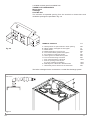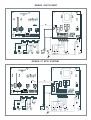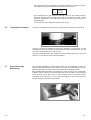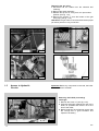
1
Installation Instructions
Type C Boilers
G.C.N:
41-116-01
47-116-08
47-116-09
47-116-13
LEAVE THESE INSTRUCTIONS
ADJACENT TO THE GAS METER
Country of destination: GB
TABLE OF CONTENTS
1.
GENERAL INFORMATION
1.1 General Instructions
1.2 Technical Information
1.3 Overall View
2.
INSTALLATION
2.1
2.2
2.3
2.4
2.5
2.6
2.7
2.8
2.9
2.10
2.11
2.12
Reference Standards
Siting the Appliance
Overall Dimensions
Clearances
Mounting the Appliance
Electrical Connection
Gas Connection
Water Connections
Flue Connection
Room Thermostat Connection
Electrical/System Diagrams
Water Circuit Diagrams
3.
COMMISSIONING
3.1
3.2
3.3
3.4
3.5
3.6
3.7
3.8
3.9
Initial Preparation
Removing the Casing
Control Panel
Initial Start-up
Operational Adjustments
Combustion Analysis
Fume Discharge Monitoring
Boiler Safety Systems
Draining the System
4.
GAS ADJUSTMENTS
- Gas Adjustment Table
4.1 Changing the Type of Gas
5.
MAINTENANCE
6.
MISCELLANEOUS
6.1 Wiring Diagram for Two Heating Zones
6.2 Wiring Diagram for Connection to Ariston Unvented Cylinder
2
B004
1.
GENERAL
INFORMATION
This manual is an integral and essential part of the product. It should be kept
with the appliance so that it can be consulted by the user and our authorised
personnel.
Please carefully read the instructions and notices about the unit contained in
this manual, as they provide impor tant information regarding the safe
installation, use and maintenance of the product.
For operating instructions please consult the separate User’s Manual.
User’s
Manual
1.1
General Information
Read the instructions and recommendations in these Installation Instructions
carefully to ensure proper installation, use and maintenance of the appliance.
Keep this manual in a safe place. You may need it for your own reference while
our Servicing Centre technicians or your installer may need to consult it in the
future.
This is a combined appliance for the production of central heating (C.H.) and
domestic hot water (D.H.W.).
This appliance must be used only for the purpose for which it is designed.
The manufacturer declines all liability for damage caused by improper or
negligent use.
No asbestos or other hazardous materials have been used in the fabrication of
this product.
Before connecting the appliance, check that the information shown on the data
plate and the table on pages 4-5 comply with the electric, water and gas mains
of the property. You will find the data plate on the reverse of the control panel.
The gas with which this appliance operates is also shown on the label at the
bottom of the boiler.
Do not install this appliance in a damp environment or close to equipment
which spray water or other liquids.
Do not place objects on the appliance.
Do not allow children or inexperienced persons to use the appliance without
supervision.
If you smell gas in the room, do not turn on light switches, use the telephone or
any other object which might cause sparks.
Open doors and windows immediately to ventilate the room.
Shut the gas mains tap (on the gas meter) or the valve of the gas cylinder and call
your Gas Supplier immediately.
If you are going away for a long period of time, remember to shut the mains gas
tap or the gas cylinder valve.
Always disconnect the appliance either by unplugging it from the mains or
turning off the mains switch before cleaning the appliance or carriyng out
maintenance.
In the case of faults or failure, switch off the appliance and turn off the gas
tap. Do not tamper with the appliance.
For repairs, call your local Authorised Servicing Centre and request the use of
original spare parts. For in-guarantee repairs contact MTS (GB) Limited
Check the following at least once a year:
1 - Check the seal of water connections, replacing the gaskets if necessary.
2 - Check the seal of the gas connections, replacing the gaskets if necessary.
B004
3
3 - Check the general condition of the appliance and of the combustion
chamber visually.
4 - Visual check of the combustion: clean burners if necessary.
5 - With reference to point 3, dismantle and clean the combustion chamber if
necessary.
6 - With reference to point 4, dismantle and clean the injectors if necessary.
7 - Visual check of the primary heat exchanger:
- check for overheating of the exchangers fins;
- clean the exhaust side of the exchanger and fan if necessary.
8 - Regulate the gas pressure, ignition pressure, partial flame, maximum flame.
9 - Check proper operation of the heating safety system:
- maximum safety temperature;
- maximum safety pressure.
10 - Check the proper operation of the gas safety system:
- gas or flame safety device;
- gas valve safety device.
11 - Check that the electrical connections have been made in compliance with
the instructions shown in the Installation Instructions.
12 - Check the efficiency of the hot water supply (flow and temperature).
13 - Check general operation of the appliance.
14 - Check the exhaust system for the combustion products.
1.2
Technical Information
23 MFFI
27 MFFI
27 RFFI SYSTEM
30 MFFI
25.6/11.0
23.1/9.2
90.2
87.8
1.2
8.6
0.4
59
1.15
2.72/3.32
0.32/0.39
2.02/2.00
29.8/12.0
27.3/10.1
91.6
88.3
1.3
7.1
0.4
62
1.4
3.16/3.86
0.37/0.45
2.35/2.32
29.8/12.0
27.3/10.1
91.6
88.3
1.3
7.1
0.4
62
1.4
3.16/3.86
0.37/0.45
2.35/2.32
33.0/12.0
30.3/10.2
92.0
88.6
1.4
6.6
0.4
61
1.4
3.49/4.05
0.41/0.47
2.60/2.57
°C
%
137
5.8
128
6.6
128
6.6
135
7.5
O2 Content
%
9.2
8.0
8.0
8.0
CO Content
Minimum Ambient Temperature
Head Loss on Water Side (max) (³T=20°C)
Residual Head of System
Heating Temperature
Domestic Hot Water Temperature
D.H.W. Flow Rate ³T=35°C
D.H.W. Flow Rate ³T=35°C
D.H.W. Flow Minimum Rate
Pressure of Domestic Hot Water
Expansion Vessel Capacity
Expansion Vessel Pre-load Pressure
Maximum Water Content in System
Maximum Heating Pressure
Nominal Pressure Natural Gas (G20-G25)
Liquid Gas (G30-G31)
Electrical Supply
Power Consumption
Protection Grade of Electrical System
Internal Fuse Rating
Weight
ppm
°C
mbar
bar
max/min °C
max/min °C
l/min
gal/min
l/min
max/min bar
l
bar
l
bar
mbar
mbar
V/Hz
W
IP
32
+5
200
0.25
82/42
56/36
9.5
2.1
2.6
6/0.2
7
1
145
3
20-25
30-37
230 / 50
150
X4D
FAST 2 AT
47
34
+5
200
0.25
82/42
56/36
11.2
2.5
2.6
6/0.2
7
1
145
3
20-25
30-37
230 / 50
190
X4D
FAST 2 AT
47
34
+5
200
0.25
82/42
----------7
1
145
3
20-25
30-37
230 / 50
190
X4D
FAST 2 AT
46.5
49
+5
200
0.25
82/42
56/36
12.3
2.7
2.6
6/.02
7
1
145
3
20-25
30-37
230 / 560
190
X4D
FAST 2 AT
47
47-116-08
47-116-09
41-116-01
47-116-13
CE Certification
Heat Input
Heat Output
Efficiency of Nominal Heat Input
Efficiency at 30% of Nominal Heat Input
Heat Loss to the Casing (³T=50°C)
Flue Heat Loss with Burner Operating
Flue Heat Loss with Burner Off
Maximum Discharge of Fumes (G20-G25)
Residual Discharge Head
Consumption at Nominal Capacity (G20-G25)
Gas Consumption after 10 Minutes*
(15°C, 1013 mbar) (G30-G31)
Temp. of exhaust fumes at nominal
capacity (G20-G25)
CO2 Content
G.C. Number
*Calculated at 70% maximum output
4
max/min kW
max/min kW
%
%
%
%
%
Kg/h
mbar
m3/h
m3
Kg/h
Kg
B004
1.3
Overall View
GENUS 23/27/30 MFFI
GENUS 27 RFFI SYSTEM
Fig. 1.1
Legend:
1.
2.
3.
4.
5.
6.
7.
8.
9.
10.
11.
12.
13.
14.
15.
16.
17.
18.
19.
20.
21.
22.
23.
24.
B004
Flue Connector
Combustion Chamber Hood
Main Heat Exchanger
Combustion Chamber Insulation Panel
Burner
Expansion Vessel
Overheat Thermostat
Spark Generator
Diverter Valve
(MFFI)
Motorised Valve
(RFFI)
Main Circuit Temperature Probe
Main Circuit Flow Switch
Domestic Hot Water Temperature Probe
Diverter Valve Microswitch
Filter Seat
Drain Valve
Secondary Heat Exchanger
Safety Valve (3 bar)
Circulation Pump with Automatic Air Release Valve
Gas Valve
Detection Electrodes
Ignition Electrodes
Fan
Venturi
Air Pressure Switch
5
2.
2.1
INSTALLATION
Reference Standards
The technical information and instructions provided herein below are intended
for the installer so that the unit may be installed correctly and safely.
The installation and initial startup of the boiler must be by a CORGI Approved
Installer in compliance with the installation standards currently in effect, as well
as with any and all local health and safety standards i.e. CORGI.
This appliance must be installed by a competent installer in
accordance with the current Gas Safety (installation & use)
Regulations
The installation of this appliance must be in accordance with the relevant
requirements of the current Gas Safety (installation & use) Regulations, the
Local Building Regulations, the current I.E.E. Wiring Regulations, the byelaws
of the local water authority, and in Scotland, in accordance with the Building
Standards (Scotland) Regulation and Health and Safety document No. 635
“Electricity at work regs. 1989”.
Installation should also comply with the following British Standard Codes of
Practice:
Low pressure
pipes
BS 6891
Boilers of rated input
not exceeding 60 kW
BS 6798
Forced circulation hot
water system
BS 5449
Installation of gas hot water
supplies for domestic purposes
( 2nd family gases)
BS 5546
Flues
BS 5440-1
Air supply
BS 5440-2
2.2
Siting the Appliance
1988
1987
1990
1990
1990
1989
The appliance may be installed in any room or indoor area, although particular
attention is drawn to the requirements of the current I.E.E. Wiring Regulations,
and in Scotland, the electrical provisions of the Building Regulations applicable
in Scotland, with respect to the installation of the combined appliance in a room
containing a bath or shower.
Where a room-sealed appliance is installed in a room containing a bath or
shower the boiler and any electrical switch or appliance control, utilising
mains electricity should be situated so that it cannot be touched by a
person using the bath or shower.
The location must permit adequate space for servicing and air circulation
around the appliance as indicated in paragraph 2.4.
The location must permit the provision of an adequate flue and termination.
For unusual locations special procedures may be necessary.
BS 6798-1987 gives detailed guidance on this aspect.
A compartment used to enclose the appliance must be designed specifically for
this purpose. No specific ventilation requirements are needed for an installation
within a cupboard
This appliance is not suitable for outdoor installation.
The type C appliances (in which the combustion circuit, air vent intake
and combustion chamber are air-tight with respect to the room in which
the appliance is installed) can be installed in any type of room.
There are no limitations with respect to ventilation and the volume of the room
itself. The boiler must be installed on a solid, permanent wall to prevent access
to the electrical parts (when live) through the aperture on the back frame.
6
B004
GENUS 23/27/30 MFFI
Overall Dimensions
890
2.3
(A-B-D-E)
(C)
GENUS 27 RFFI SYSTEM
5
38
465
30
A = Central Heating Flow (3/4”)
B = Domestic Hot Water Outlet (1/2”)
C = Gas Inlet (3/4”)
D = Domestic Cold Water Inlet (1/2”)
E = Central Heating Return (3/4”)
F = Cylinder Flow (3/4”)
G = Cylinder Return (3/4”)
99
85
99
(F - G)
155
132
AF
67
65
49
Legend:
(A - D - E)
(C)
208
C DGE
Fig. 2.1
2.4
Clearances
In order to allow for access to the interior of the boiler for maintenance purposes, the
boiler must be installed in compliance with the clearance requirements indicated in the
diagram below.
GENUS 27 RFFI SYSTEM
160
197
400
110
GENUS 23/27/30 MFFI
60
60
0 nx-5 ai3 m
450
300
Fig. 2.2
B004
7
2.5
Mounting the Appliance Fasten the boiler in place using the template and anchors supplied with the
unit. It is highly recommended that a spirit level be used to position the boiler so
that it is perfectly level.
For additional information, please consult the instructions contained in the
connection kit and the flue kit.
2.6
Electrical Connection
For safety purposes, have a competent person carefully check the electrical
system in the property, as the manufacturer will not be held liable for damage
caused by the failure to earth the appliance properly or by anomalies in the
supply of power. Make sure that the residential electrical system is adequate for
the maximum power absorbed by the unit, which is indicated on the rating plate.
In addition, check that the section of cabling is appropriate for the power
absorbed by the boiler.
The boiler operates with alternating current, as indicated in the technical data
table (1.2), where the maximum absorbed power is also indicated. Make sure
that the connections for the neutral and live wires correspond to the indications
in the diagram. The appliance electrical connections are situated on the reverse
of the control panel (see the servicing manual for further information)
Fig. 2.3
Important!
In the event that the power supply cord must be changed, replace it with one
with the same specifications. Make the connections to the terminal board
located within the control panel, as follows:
- The yellow-green wire should be connected to the terminal marked with the
earth symbol; make sure to re-use the ferrule mounted on the other supply
cord;
- The blue wire should be connected to the terminal marked “N”;
- The brown wire should be connected to the terminal marked “L”.
Note: The diagrams for the electrical system are indicated in section 2.11.
Warning, this appliance must be earthed.
External wiring to the appliance must be carried out by a qualified technician
and be in accordance with the current I.E.E. Regulations and applicable local
regulations. The Genus range of boilers are supplied for connection to a 230 V~
50 Hz supply.
The supply must be fused at 3 A.
The method of connection to the electricity supply must facilitate complete
electrical isolation of the appliance, by the use of a fused double pole isolator
having a contact separation of at least 3 mm in all poles or alternatively, by
means of a 3 A fused three pin plug and unswitched shuttered socket outlet
both complying with BS 1363.
The point of connection to the Electricity supply must be readily accessible and
adjacent to the appliance unless the appliance is installed in a bathroom when
this must be sited outside the bathroom.
2.7
8
Gas Connection
The local gas supplier contractor connects the gas meter to the service pipe.
If the gas supply for the boiler serves other appliances ensure that an adequate
supply is available both to the boiler and the other appliances when they are in
use at the same time.
Pipe work must be of an adequate size. Pipes of a smaller size than the boiler
inlet connection should not be used.
B004
2.8
Water Connections
View of the Boiler Connections
GENUS 23/27/30 MFFI
GENUS 27 RFFI SYSTEM
C
C
A
B
D
E
A
D
I
I
F
Legend
E
G
Fig. 2.4
A = Central Heating Flow
B = Domestic Hot Water Outlet
C = Gas Inlet
D = Domestic Cold Water Inlet
E = Central Heating Return
F = Cylinder Flow
G = Cylinder Return
I = Safety Valve
Fig. 2.5
Fitting the connection kit to the
Genus 27 RFFI System only.
It will be noted that the kit has two
connections not required for this boiler
i.e. the domestic cold inlet “E” and the
domestic hot water outlet “B” (see fig.
2.4).
Although the cold water main supply
must be connected to the isolation valve
for the purpose of operating the fillingloop, the isolation valve is NOT
connected to the boiler and should be left
in the OFF position.
The D.H.W. outlet is capped-off on the
boiler, therefore not requiring the
isolation valve to be used.
The Genus 27 RFFI System has 2 x 3/4"
B.S.P. male threads for the cylinder flow
and return. It is recommended that 2 x
22mm x 3/4" female iron fittings (not
supplied) be used on these connections
(using P.T.F.E. tape), before the boiler is
mounted on the wall.
B004
Central Heating
Detailed recommendations are given in BS 6798:1987 and BS 5449-1:1990,
the following notes are given for general guidance.
Pipe Work:
Copper tubing to BS EN 1057:1996 is recommended for water pipes. Jointing
should be either with capillary soldered or compression fittings.
Where possible pipes should have a gradient to ensure air is carried naturally
to air release points and water flows naturally to drain taps.
The appliance has a built-in automatic air release valve, however it should be
ensured as far as possible that the appliance heat exchanger is not a natural
collecting point for air.
Except where providing useful heat, pipes should be insulated to prevent heat
loss and avoid freezing.
Particular attention should be paid to pipes passing through ventilated spaces
in roofs and under floors.
By-pass:
The appliance includes an automatic by-pass valve, which protects the main
heat exchanger in case of reduced or interrupted water circulation through
the heating system, due to the closing of thermostatic valves or cock-type
valves within the system.
System Design:
This boiler is suitable only for sealed systems.
Drain Cocks:
These must be located in accessible positions to permit the draining of the
whole system. The taps must be at least 15mm nominal size and
manufactured in accordance with BS 2870:1980.
Safety Valve Discharge:
The discharge should terminate facing downwards on the exterior of the
building in a position where discharging (possibly boiling water & steam) will
not create danger or nuisance, but in an easily visible position, and not cause
damage to electrical components and wiring.
The discharge must not be over an entrance or a window or any other type of
public access.
9
Air Release Points:
These must be fitted at all high points where air naturally collects and must
be sited to facilitate complete filling of the system.
The appliance has an integral sealed expansion vessel to accommodate the
increase of water value when the system is heated.
It can accept up to 7 l (1.5 gal) of expansion water. If the heating circuit has
an unusually high water content, calculate the total expansion and add an
additional sealed expansion vessel with adequate capacity.
Mains Water Feed - Central Heating:
There must be no direct connection to the mains water supply even through a
non-return valve, without the approval of the Local Water Authority.
Filling:
A temporary method for initially filling the system and replacing lost water
during servicing and initial filling (in accordance with Water Supply Byelaw
14), is provided as an intergal part of the connection kit (see fig. 2.5). The
flexible hose must be removed once the system has been filled. The D.H.W.
inlet valve on the connection kit has two postions, one for winter and one for
the summer. This enables the flow-rate through the appliance to be adjusted
so that a sensible D.H.W. temperature may be achieved throughout the year.
Domestic Water
The domestic water must be in accordance with the relevant recommendation
of BS 5546:1990. Copper tubing to BS EN 1057:1996 is recommended for
water carrying pipe work and must be used for pipe work carrying drinking
water.
Residual Head of the Boiler
27/30 kW
23 kW
2.9
10
Flue Connections
Flue System
The provision for satisfactory flue termination must be made as described
in BS 5440-1.
The appliance must be installed so that the flue terminal is exposed to outdoor air.
The terminal must not discharge into another room or space such as an
outhouse or lean-to.
It is important that the position of the terminal allows a free passage of air
across it at all times.
The ter minal should be located with due regard for the damage or
discolouration that might occur on buildings in the vicinity.
In cold or humid weather water vapour may condense on leaving the flue
terminal.
The effect of such “steaming” must be considered.
If the terminal is less than 2 metres above a balcony, above ground or above a
flat roof to which people have access, then a suitable terminal guard must be
fitted. When ordering a terminal guard, quote the appliance model number.
B004
A suitable terminal guard is available from:
TOWER FLUE COMPONENTS
Morley Road
Tonbridge
Kent TN9 1RA
The minimum acceptable spacing from the terminal to obstructions and
ventilation openings are specified in Fig. 2.6
BC
F
G
F D
HI
J
A
E
L
K
TERMINAL POSITION
mm
A - Directly below an open window or other opening
B - Below gutters, solid pipes or drain pipes
C - Below eaves
D - Below balconies or car-port roof
E - From vertical drain pipes and soil pipes
F - From internal or external corners
G - Above ground or below balcony level
H - From a surface facing a terminal
I - From a terminal facing a terminal
J - From an opening in the car port
(e.g. door, window) into dwelling
K - Vertically from a terminal in the same wall
L - Horizontally from a terminal in the same wall
300
75
200
200
75
300
300
600
1200
G
Fig. 2.6
1200
1500
300
The boiler is designed to be connected to a coaxial flue discharge system.
Ø 60/100 mm
Fig. 2.7
B004
11
In addition, it is also possible to use a split system by fitting a special adapter to
the flue discharge collar and using one of the apertures for the air vent intake
located on the top part of the combustion chamber (A).
Ø 80 mm
A
A
A
Ø 80 mm
Fig. 2.8
This procedure must be done as follows:
1 - Remove the air vent intake you want to use, in the area indicated in
Fig. 2.9, by breaking the perforated ring.
2 - Use a tool to grasp the lid and remove it completely.
3 - Clean any burrs or sharp edges with a knife or an appropriate tool.
A
Fig. 2.9
12
Fig. 2.10
B004
In Fig. 2.11 below, several different types of flue systems are shown.
For additional information regarding the flue accessories, please consult the
Flue Pipe Accessories manual.
Fig. 2.11
B004
13
Coaxial
Systems
Twin Pipe
Systems
Exhaust Type
30 kW
Use of Restrictor on Discharge Side
L * < 0.5 m
27 kW
L * < 0.5 m
23kW
L * < 0.5 m
45 mm
30 kW
ø 60/100
42 mm
23kW
27 kW
3m
Diameter of
Pipes
(mm)
4m
L * < 0.5 m
Maximum Extension
Exhaust/Air
23 kW - 27 kW
30kW
C12 (xx)
L * < 0.5 m
L > 4.5 m
L * < 0.5 m
L > 6.5 m
L > 4.5 m
ø 60/100
L > 4.9 m
L > 6.5 m
L > 4.5 m
3m
L < 7.5 m
L > 4.9 m
L > 6.5 m
L > 4.5 m
4m
L<5m
L < 7.5 m
L > 4.9 m
L < 5.3 m
C32 (xx)
L<7m
L<5m
L < 7.5 m
L > 4.9 m
L * < 0.5 m
30 kW
ø 80
L<7m
L<5m
L < 7.5 m
L * < 0.5 m
27 kW
50 m
ø 80
L<7m
L<5m
L * < 0.5 m
23 kW
46 m
50 m
ø 80
L<7m
ø 60/100
54 m
46 m
50 m
ø 80
3m
C12 (xy)
54 m
46 m
15 m
4m
C32 (xy)
54 m
17 m
C42 (xx)
C42 (xy)
17 m
Risk of Condensation Forming
(*) L = Length of Piping
14
C52 (xy)
In calculating the lengths of the
pipes, the maximum length must also
take into consideration the values for
the exhaust/air intake end terminals,
as well as 90° elbows for coaxial
systems.
The C52 types must comply with the
following requirements:
1. The discharge/intake vent pipes
must have the same diameter of ø
80 mm.
2. The maximum combined flue
length is 17 m for Models Genus
23/27 MFFI/RFFI and 15 m for
Model Genus 30 MFFI. In this case
the minimum length for the air
intake pipe is 1 meter ; the
maximum length of ver tical
exhaust pipe must be a maximum
of 12 m.
3. If an elbow is inserted into the
discharge/ventilation system, the
calculation of the overall extension
must take into consideration the
values for each curve, as indicated
in the table.
4. The exhaust pipe must extend at
least 0.5 m above the ridge of the
roof if it is located on a side other
than that for the air intake (this is
not obligatory if the exhaust and air
intake pipes are located on the
same side of the building).
B004
2.10 Room Thermostat
Connection
In order to perform this procedure, remove the boiler casing as indicated in
section 3.2. Then proceed as follows:
1 Remove the two screws “A” in order to remove the cover, release the two
clips “B” and lift and rotate down the control panel box.
2 Open the cover “C” on the left hand side of the compartment.
3 Insert the wire for the connection of the room thermostat into the cable
clamp “D”, as indicated in photo 3.
1
2
B
3
D
C
A
4 Remove the grommet “E” shown in the photo 4, make a hole in it and pass
the room thermostat wire through.
5 Remove the link located in the terminal block and connect the wire.
6 Replace the grommet and the terminal block to their original positions, close
the cover on the grommet compartment and fasten the wire-clamp “D” in
place.
7 If a remote time clock is to be fitted, disconnect the integral time clock plug
from the P.C.B.
8 Using a volt-free switching time clock, connect the switching wires from the
time clock following points 1-6 above.
9 If using a time clock and room thermostat, these must be connected in
series as per points 1-8 above.
Note: Only a two-wire type room thermostat can be used.
For details on fitting the D.H.W. probe (Genus 27 RFFI only),
please consult the separate instruction sheet supplied with the
probe.
An anti-frost device is built-in to the appliance’s electronic
regulation system.
4
5
E
B004
6
D
15
2.11
Electrical Diagram
Legend:
AT
BT
A
B
C
D
E
F
G
H
I
J
K
L
M
N
O
P
Q
R
S
T
U
V
W
X
Y
Z
Aa
=
=
=
=
=
=
=
=
=
=
=
=
=
=
=
=
=
=
=
=
=
=
=
=
=
=
=
=
=
High Voltage P.C.B.
Low Voltage P.C.B.
Remote Connector Kit
Flame Failure L.E.D.
Insufficient Water Pressure L.E.D.
Water Temperature Indicator L.E.D.s
Overheat Thermostat Warning L.E.D.
System Reset Button
Selector Knob for Operating Mode
Domestic Hot Water Temp. Adjustment
Central Heating Temp. Adjustment
Wire Connector for Room Thermostat
Connector for Total Check System
Selector for Local/Remote Control
Anti-cycling Device Adjustment for Heating
Soft-light Adjustment
Max Heating Temperature Adjustment
Time Clock Connection
On/Off L.E.D.
On/Off Switch
Interface Wire for P.C.B.s
Relay Motorised Valve
Ignitor Relay
Gas Valve Relay
Fan Relay
Circulation Pump Relay
Selector TCS2
Link for Continuous Pump Run
Adaptor (British Gas use only)
A01 =
A02 =
A03 =
A04 =
A05 =
A06 =
A07 =
A08 =
A09 =
A10 =
A11 =
A12 =
Air Pressure Switch
Fan
Gas Valve
Ignitor
Motorised Valve
Circulation Pump
Flame Detector
Earth Terminal
Flame Detection Circuit
Flame Indicator L.E.D.
Transformer
Filter
B01 =
B02 =
B03 =
B04 =
Over Heat Thermostat
External Thermostat
Gas Valve Modulator
D.H.W. Probe Sensor Cylinder (RFFI SYSTEM models only)
B05 =
B06 =
B07 =
Heating Sensor
Pressure Switch for Heating Circuit
Microswitch for Diverter Valve (MFFI models only)
Colours
Gry
Rd
Bl
Grn/Yll
Wh
Brn
Blk
Wh/Rd
16
= Grey
= Red
= Blue
= Yellow/Green
= White
= Brown
= Black
= White/Red
B004
GENUS 23/27/30 MFFI
Aa
GENUS 27 RFFI SYSTEM
Aa
B004
17
GENUS 23/27/30 MFFI
CN202
P
GENUS 27 RFFI SYSTEM
P
18
B004
2.12
Water Circuit Diagram
GENUS 23/27/30 MFFI
Legend
1. Air Pressure Switch
2. Fan
3. Main Heat Exchanger
4. Burner
5. Electronic Ignitor and
Electronic Flame Detector
6. Gas Valve
7. Overheat Thermostat
8. Heating Sensor
9. Diverter Valve (MFFI)
Motorised Valve (RFFI)
10. Main Flow Switch Including
Safety Pressure Switch for
Primary Circuit
11. Automatic By-pass
12. Microswitch for Diverter Valve
13. Sensor for Domestic Hot Water
14. Secondary Heat Exchanger
15. Domestic Water Inlet Filter
16. Drain Valve
17. Safety Valve
GENUS 27 RFFI SYSTEM
18. Water Pressure Gauge
19. Circulation Pump with Automatic
Air Valve
20. Expansion Vessel
A. Central Heating Flow
B. Domestic Hot Water Outlet
C. Gas Inlet
D. Domestic Cold Water Inlet
E. Central Heating Return
F. Cylinder Flow
G. Cylinder Return
B004
19
3.
COMMISSIONING
3.1
Initial Preparation
Preliminary electrical system checks to ensure electrical safety must be carried
out by a competent person i.e. polarity, earth continuity, resistance to earth and
short circuit.
Filling the Heating System:
Remove the panels of the case and lower the control panel (see point 3.2. for
further information).
Open the central heating flow and return cocks supplied with the connection
kit.
Unscrew the cap on the automatic air release valve one full turn and leave
open permanently.
Close all air release valves on the central heating system.
Gradually open valve(s) at the filling point (filling-loop) connection to the
central heating system until water is heard to flow, do not open fully.
Open each air release tap starting with the lower point and close it only when
clear water, free of air, is visible.
Purge the air from the pump by unscrewing anticlockwise the pump plug and
also manually rotate the pump shaft in the direction indicated by the pump
label to ensure the pump is free.
Close the pump plug.
Continue filling the system until at least 1 bar registers on the pressure
gauge.
Inspect the system for water soundness and remedy any leaks discovered.
Filling of the D.H.W. System:
Close all hot water draw-off taps.
Open the cold water inlet cock supplied with the connection kit.
Open slowly each draw-off tap and close it only when clear water, free of
bubbles, is visible
Gas Supply:
Inspect the entire installation including the gas meter, test for soundness and
purge, all as described in BS 6891:1988.
Open the gas cock (supplied with the connection kit) to the appliance and
check the gas connector on the appliance for leaks.
When the installation and filling are completed turn on the central heating
system (sect. 3.4) and run it until the temperature has reached the boiler
operating temperature. The system must then be immediately flushed through.
The flushing procedure must be in line with BS 7593:1992 Code of practice for
treatment of water in domestic hot water central heating systems.
During this operation, we highly recommend the use of a central heating
flushing detergent (Fernox Superfloc or equivalent), whose function is to
dissolve any foreign matter that may be in the system.
Substances different from these could create serious problems to the
pump or other components.
The use of an inhibitor in system such as Fernox MB-1 or equivalent is strongly
recommended to prevent corrosion (sludge) damaging the boiler and system.
Failure to carry out this procedure may invalidate the appliance warranty.
3.2
Removing the Casing
1
To dismantle the front part of
the casing, proceed as follows:
1. Loosen the two screws “F”
located on the bottom part
of the boiler until the
first thread on the screws
appears;
F
20
B004
2
3
4
2. Lift the front panel up until it stops after the click;
3. Remove the front panel from the rest of boiler casing;
4. Unhook the two cords from the location slots.
3.3
Control Panel
GENUS 23/27/30 MFFI
A - Ignition Lockout Reset
Button/Safety
(Overheat)Thermostat Reset
B - Ignition Lockout L.E.D.
C - Selector Knob for
Summer/Winter/Flue Analysis
Modes*
D - Low System Water Level L.E.D.
E - Temperature Adjustment Knob
for Domestic Hot Water
F - Heating System Thermometer
G - Safety (Overheat)Thermostat
GENUS 27 RFFI SYSTEM
Intervention L.E.D.
H - Adjustment Knob for Heating
Temperature
I - On/Off L.E.D.
L - On/Off Switch
O - System Pressure Gauge
* Warning the flue analysis mode must only be selected by a qualified service engineer.
B004
21
3.4
Initial Start-up
The checks to be run before initial start-up are as follows:
1. Make sure that:
- the screw on the automatic air valve has been loosened when the
system is full;
- If the water pressure in the system is below 1 bar, bring it up to the appropriate level;
- Check to see whether the gas cock is closed;
- Make sure that the electrical connection has been made properly and that
the earth wire is connected to an efficient earthing system;
- Supply power to the boiler by pressing the On/Off switch <L> - the L.E.D. “I”
will turn on - turn the selector knob “C” to the <winter> setting. This will
start the circulation pump. After 7 seconds, the boiler will signal a shutdown due to failure ignition. Leave the boiler as it is until all of the air has
been bled from the lines.
- Loosen the cap on the head of the pump to eliminate any air pockets;
- Repeat the procedure for bleeding the radiators of air;
- Open the taps for a brief period;
- Check the system pressure and, if it has dropped, open the filling loop
again to bring the pressure back up to 1 bar.
2. Check the exhaust flue for the fumes produced by combustion.
3. Make sure that all gate valves are open;
4. Turn on the gas cock and check the seals on the connections, including the
one for the burner, making sure that the meter does not signal the passage
of gas. Check the connections with a soap solution and eliminate any leaks.
5. Press the reset button “A” for the lighting system; the spark will light the
main burner. If the burner does not light the first time, repeat the procedure.
6. Check the minimum and maximum pressure values for the gas going to the
burner; adjust it if needed using the values indicated in the table in
section 4.
(See sect of the servicing manual).
3.5
Operational
Adjustments
The boiler was designed to make regulation easy. To access the adjustment
and control area, simply remove the cover by unscrewing the screws “A” and
“C” and lift up the small service panels “B1” and “B2” respectively. The first
provides access to the control (low voltage) P.C.B., while the second makes it
possible to work on the power supply P.C.B.
A
B1
B2
C
The service panel “B2” also provides access to:
- the power supply cord connector;
- the fuses;
- the selector knob for continuous
operation of the circulation pump.
The service panel “B1” also provides access to:
- the potentiometer for regulating the ignition delay (anti-cycling) feature, which
can be set from 0 to 2 minutes (factory set at 1 minute);
22
B004
- the potentiometer for regulating the soft-light feature, the setting for which
can range from the minimum thermal power to the maximum:
G20
G25
G30-31
5 mbar
18 mbar
19 mbar
- the potentiometer for the maximum thermal power for the heating system,
maximum thermal power setting (factory set at the maximum value, unless
indicated otherwise on the adhesive sticker located in proximity to the
potentiometer);
- The connection to the diagnosis device (TCS-TCS2).
3.6
Combustion Analysis
The boiler is designed to make it easy to analyse the combustion by-products.
Using the especially designed apertures, readings can be taken on the
temperature of the combustion by-products and of the combustion air, as well
as of the concentrations of O2 and CO2, etc.
The best maximum-power test conditions for the heating system are when the
selector “C” is turned to the flue analysis setting.
3.7
B004
Fume Discharge
Monitoring
The discharge/ventilation of the exhaust fumes can be monitored to check for
losses in general pressure in the system. This is done to eliminate the cause of
lighting failure with the main burner not indicated by a shutdown status.
With a differential manometer connected to the test socket on the combustion
chamber, the DP value for the air pressure switch can be taken. The measured
value should not be less than 10 mbar under maximum thermal power
conditions (with the knob “C” on the flue test setting) in order for the unit to
function properly and without interruption.
23
3.8
Boiler Safety
Systems
The boiler is equipped with the following safety systems (see section 3.3 for
references):
1. - Ignition Failure
This control signals an ignition failure on the burner 7 seconds after a lighting
failure. The L.E.D. “B” will turn on to signal the shutdown status.
The system can be reset by pressing and releasing the button “A” after
checking to make sure that the gas valve is open. Repeat this process until the
burner lights.
2. - Circulation Failure
This control signals that the safety pressure switch on the primary circuit has
not sensed a pressure of at least 1 bar within 40 seconds of the activation of
the circulation pump, it shuts off the boiler and lights the L.E.D. “D” The system
can be reset (after the pressure has been brought up to the proper level) by
using the On/Off switch “L”.
3. - Overheating
This control shuts off the boiler in the case where the primary circuit reaches a
temperature in excess of 110°C. The L.E.D. “G” will come on to signal this shutoff status. After the system has been allowed to cool, the system can be reset
by pressing the button “A”.
4. - Limescale Build-up
This is an indirect control (actuated through the regulation of the temperature in
the primary heat exchanger) on the formation of limescale in the secondary
heat exchanger. Regardless of the flow rate and the temperature in the circuit
for the domestic hot water, the temperature is limited to 62°C.
5. - Anti-frost Device
The boiler is equipped with a device that automatically lights the main burner
when the temperature in the delivery line to the system drops below 5°C. The
boiler will continue to operate until the temperature in question reaches about
58°C.
This device is activated on a properly operating boiler if:
- the system pressure is between the acceptable values;
- the power supply to the unit is on;
- the unit is supplied with gas.
This feature is enabled also when the boiler is in summer operating mode.
6. - Safety Shut-off
At the start of every lighting phase, the P.C.B. performs a series of internal
controls. If a malfunction occurs, the boiler will shutdown until the problem has
been resolved.
3.9
Draining the System
Draining the heating system.
The heating system must be emptied as follows:
- Turn off the boiler;
-Open the drain valve for the system and place a container below to catch
the water that comes out;
- Empty the system at the lowest points (where present). If you plan on not
using the heating system for an extended period of time, it is recommended
that you add antifreeze with an ethylene glycol base to the water in the
heating lines and radiators if the ambient temperature drops below 0°C during
the winter.
This makes repeated draining of the entire system unnecessary.
Draining the domestic hot water system.
Whenever there is the danger of the temperature dropping below the freezing
point, the domestic hot water system must be drained as follows:
- Turn off the general water valve for the household plumbing system;
- Turn on all the hot and cold water taps;
- Empty the remaining water from the lowest points in the system (where
present).
24
B004
4.
GAS ADJUSTMENTS
CATEGORY II2H3+
Lower Wobbe Index (15°C;1013mbar)
Nominal Delivery Pressure
Minimum Delivery Pressure
Methane Gas
G20
MJ/m3h
mbar
mbar
Liquid Butane Gas
G30
45.67
20
17
Liquid Propane Gas
G31
80.58
30
20
70.69
37
25
0.72
---2.02
0.72
---2.02
23 MFFI
Main Burner: n. 13 jets (ø)
Consumption (15°C; 1013mbar)
Consumption (15°C; 1013mbar)
Gas Cock Outlet Pressure
max - min
mm
mc/h
Kg/h
1.25
2.72
----
mbar
11.4- 2.0
mc/h
Kg/h
1.25
3.16
----
mbar
11.4-2.0
mc/h
Kg/h
1.30
3.49
----
mbar
11.4-1.4
27.5 (*) - 5.0
35.0 (*) - 7.0
27 MFFI - 27 RFFI System
Main Burner: n. 15 jets (ø)
Consumption (15°C; 1013mbar)
Consumption (15°C; 1013mbar)
Gas Cock Outlet Pressure:
max - min
0.72
---2.35
0.72
---2.32
(*) - 5.0
(*) - 7.0
0.77
---2.60
0.77
---2.57
(*) - 4.1
(*) - 5.6
30 MFFI
Main Burner: n. 15 jets (ø)
Consumption (15°C; 1013mbar)
Consumption (15°C; 1013mbar)
Gas Cock Outlet Pressure:
max - min
(1mbar = 10,197column of water)
The outlet pressure of the gas cock is obtained by completely loosening the
screw on the solenoid. The maximum pressure of the gas to the burner will be
equal to the nominal delivery pressure minus the head loss within the gas
valve.
4.1
Changing the Type of
Gas
CATEGORY II2H3+
Recommended Soft-light Pressure
(mbar)
B004
The boiler can be converted to use either methane (natural) gas (G20) or
LPG (G30 - G31) by an Authorised Service Centre.
The operations that must be performed are the following:
1. Replace the jets on the main burner (see table in section 4);
2. Adjust the maximum and minimum thermal capacity values for the boiler
(see table in section 4);
3. Replace the gas rating plate;
4. Adjust the maximum thermal power setting;
Methane Gas
Liquid Butane Gas
Liquid Propane Gas
G20
G30
G31
5-5.5
17 - 18
18 - 19
25
5. Adjust the soft-light feature;
6. Adjust the delayed lighting feature for the heating system (can be set from
0 to 2 mins.).
5.
26
MAINTENANCE
It is recommended that the following checks be made on the boiler at
least once a year:
1 - Check the seals for the water connections; replacement of any faulty seals.
2 - Check the gas seals; replacement of any faulty gas seals.
3 - Visual check of the entire unit.
4 - Visual check of the combustion process or analysis of flue gas (see ref 3.6)
and cleaning of the burners if needed.
5 - If called for by check no. 3, dismantling and cleaning of the combustion
chamber.
6 - If called for by check no. 4, dismantling and cleaning of the injectors.
7 - Visual check of the primary heat exchanger:
- check for overheating in the blade assembly;
- clean the exhaust fan if needed.
8 - Adjustment of the flow rate of the gas: flow rate for lighting, partial load and
full load.
9 - Check of the heating safety systems:
- safety device for maximum temperature;
- safety device for maximum pressure.
10 - Check of the gas safety systems:
- safety device for lack of gas or flame ionisation (detection electrode);
- safety device for gas cock.
11 - Check of the electrical connection (make sure it complies with the
instructions in the manual).
12 - Check of domestic hot water production efficiency (delivery rate and temperature)
13 - Check of the general performance of the unit.
14 - General check of the discharge/ventilation of the combustion byproducts.
B004
B004
240V
MAINS INPUT (3 AMP)
3
8
2
2
T6360B
ROOM
THERMOSTAT
ZONE 2
L
1
N
2
E
3
4
E
8
E
1
2
4
4
E
E
E
5
N
N
3
L
4
N
7
6
L
N
N
L
L
3
L
6
L
6
Towerchron MP
Link 1-4/6-11
ZONE 2
4
Randall 3020 P
and 3060
4
3
E
1 0
1 0
4
1
1
E
N
2
6
E
E
N
HW HTG
ON ON
1
L
N
N
N
2
2
1
L
2
N
L
L
L
L
L
1
1
2
ZONE 1
PROGRAMMER
3
Randall 922, 972
Link L-2-5
ACL LS522, LS722
Towerchron 2000
6
Towerchron FP
Link 1-5/4-7-9
3
7
Sunvic ET 1451
Link 2-3-6
Sunvic DHP 2201
3
N
• 3
ZONE 1
6
3
SWITCHMASTER 805, 900
Switchmaster 400, 600
4
E
E
E
N L
N L
N L
1
Based on Honeywell controls
BOILER
Remove internal time clock plug
from the the P.C.B. then connect
room stat terminal block on the
reverse of the boiler control panel
(see section 2.10) to 9 + 10 on
the junction box.
PROGRAMMER
8
2
4
4
N
1
Switchmaster
Symphony, Sonata
L
2
BOILER ELECTRICAL SUPPLY CABLE
ZONE 2
Sangamo 410 Form 1
Link 3-6
1
3
Randall 701, 702
Link L-6-5
Sangamo M5
Link 1-6
4
Randall 4033
Link 1-6
1
3
Randall 102/102 E
Link 3-6
Potterton EP2000/3000 Link L-5 EP2001/3001
3
Landis & Gyr RWB20
Microgyr
3
3
Landis & Gyr RWB2
Glowworm Mastermind
• 10
E
• 9
4
3
1
GREEN/YELLOW
• 7
Horstmann 425, 525, 527
Link L-2-5
9
10
L
GREY
ORANGE
• 6
L
2
1
6
N
8
BLUE
N
BROWN
Potterton Miniminder
4
1
4
• 5
3
• 4
A/27 MFFI - A/27 MFFI
Genus 23-27-30 MFFI
Genus 27 RFFI System
2
N
2
E
• 1
5
5
TYPICAL
JUNCTION BOX
2
3
3
3
Pegler Sunvic
SP 50/100 (Link L-3)
V4043H
VALVE
10
GREEN/YELLOW
9
10
Drayton Tempus 7
L
4
1
9
ORANGE
N
T6360B
ROOM
THERMOSTAT
2
2
3
GREY
3
ZONE1
4
5
BLUE
6
BROWN
6
V4043H
VALVE
1
Wiring Diagram for
Two Heating Zones
2
6.1
ST 6400/ST 6300 ST 6200 3
3
MISCELLANEOUS
4
1
Honeywell ST 699B 1002
Link L-5-8
6
6.
• 2
• 8
If a room thermostat is not required on Zone 1, insert a link
between 4 + 5 on the junction box.
If a room thermostat is not requied on Zone 2, insert a link
between 6 + 8 on the junction box.
27
1
2
28
C/P
Cylinder
thermostat
Thermal
cut-out
1 C/P
1
8
P
6
2
Not
used
Sangamo 410 Form 1
Link 3-6
4
8
8
1
2
2
4
4
E
E
E
E
E
E
4
4
N
7
5
N
N
N
N
N
3
3
L
6
6
L
L
L
L
L
4
Randall 3020 P
and 3060
E
E
HTG
ON
E
E
N
N
N
N
2
2
1
1
N
N
N
N
• 3
L
L
L
L
1
1
2
2
L
L
L
L
PROGRAMMER
2
6
3
Randall 922, 972
Link L-2-5
10
4
6
Towerchron MP
Link 1-4/6-11
10
3
6
Towerchron FP
Link 1-5/4-7-9
3
ACL LS522, LS722
6
Sunvic DHP 2201
4
HW
ON
7
Sunvic ET 1451
Link 2-3-6
1
1
4
Towerchron 2000
3
3
SWITCHMASTER 805, 900
Switchmaster 400, 600
1
Switchmaster
Symphony, Sonata
E
A/27 MFFI - A/27 MFFI
Genus 23-27-30 MFFI
Genus 27 RFFI System
9
Remove internal time clock plug
from the the P.C.B. then connect
room stat terminal block on the
reverse of the boiler control panel
(see section 2.10) to 9 + 10 on
the junction box.
2
N
N
N
3
E
E
E
L
L
L
1
Based on Honeywell controls
BOILER
10
BOILER ELECTRICAL SUPPLY CABLE
PROGRAMMER
1
1
3
Sangamo M5
Link 1-6
4
1
Randall 102/102 E
Link 3-6
Randall 701, 702
Link L-6-5
3
Potterton EP2000/3000 Link L-5 EP2001/3001
Randall 4033
Link 1-6
3
3
• 10
Potterton Miniminder
240V
MAINS INPUT (3 AMP)
Landis & Gyr RWB20
Microgyr
3
4
E
• 9
3
2
Landis & Gyr RWB2
Glowworm Mastermind
N
4
1
1
L
• 7
Horstmann 425, 525, 527
Link L-2-5
3
L
V4043H
HOT WATER VALVE
L
GREEN/YELLOW
• 6
N
10
N
ORANGE
4
9
4
GREY
• 5
3
2
3
BLUE
5
• 4
Drayton Tempus 7
8
ST 6400/ST 6300 ST 6200
BROWN
2
V4043H
HEATING VALVE
Pegler Sunvic
SP 50/100 (Link L-3)
3
L
10
GREEN/YELLOW
N
9
ORANGE
• 1
3
TYPICAL
JUNCTION BOX
6
2
GREY
1
5
BLUE
2
T6360B
ROOM
THERMOSTAT
3
BROWN
4
2
6
2
1
5
2
3
3
4
4
1
Honeywell ST 699B 1002
Link L-5-8
6
6.2
Wiring Diagram for
Connection to Ariston
Unvented Cylinder
• 2
• 8
B004
NOTES
B004
NOTES
B004
30
31
B004
Merloni TermoSanitari SpA - Italy
Commercial subsidiary: MTS (GB) LIMITED
MTS Building
Hughenden Avenue,
High Wycombe
Bucks HP13 5FT
Telephone: (01494) 755600 Fax: (01494) 459775
Technical Service Hotline: (01494) 539579
B004 - Cod. 23 99 84 1259 111 - Stampa: bieffe RECANATI
Manufacturer:
Servicing Instructions
Type C Boilers
G.C.N:
41-116-01
47-116-08
47-116-09
47-116-13
LEAVE THESE INSTRUCTIONS
ADJACENT TO THE GAS METER
TABLE OF CONTENTS
Page No.
1. SERVICING INSTRUCTIONS
1.1 Replacement of Parts
3
1.2 To Gain General Access
- Removing the Front Panel
- Removing the Bottom Cover
- Removing the Side Panels
3
4
4
1.3 Access to the Combustion Chamber
- Removing the Sealed Combustion Chamber
- Removing the Burner and Injectors
- Removing the Electrodes
- Removing the Main Heat Exchanger
- Removing the Air Pressure Switch
- Removing the Venturi Device
- Removing the Fan
5
5
6
7
7
8
8
1.4 Servicing and Removal of the Gas Valve
- Setting Gas Pressure
- Removing the Spark Generator (SIT Sigma Gas Valve)
- Removing the Spark Generator (SIT Tandem Gas Valve)
- Removing the Gas Valve
10
12
13
14
1.5 Access to the Hydraulic Circuit
- Removing the D.H.W. (Secondary) Exchanger
- Removing the Safety Valve
- Removing the Automatic Air Vent
- Removing the Main Flow Circuit Switch
- Removing the Pump
- Removing the Pressure Gauge
- Removing the Expansion Vessel
- Removing the Overheat Thermostat
- Removing the Heating Temperature Sensor (N.T.C.)
- Removing the D.H.W. Temperature Sensor (N.T.C.)
- Removing the Diverter Valve (Genus 27 RFFI Only)
14
15
15
15
16
16
17
17
17
18
18
1.6 Access to the Control System
- Checking the Fuses
- Removing the Time Clock
- Removing the P.C.B.s
19
19
20
2. FAULT FINDING
2.1 Fault Finding Guide (Flow-chart)
2.2 Fault Finding Using the Total Check System
21
26
3. ELECTRICAL DIAGRAMS
2
3.1 Electrical Connection
3.2 Functional Flow Connection
27
29
4. SHORT SPARE PARTS LIST
30
B005
1.
SERVICING
INSTRUCTIONS
To ensure efficient safe operation, it is recommended that the boiler is
serviced annually by a competent person.
Before starting any servicing work, ensure both the gas and electrical
supplies to the boiler are isolated and the boiler is cool.
Before and after servicing, a combustion analysis should be made via the flue
sampling point (please refer to the Installation Manual for further details).
After servicing, preliminary electrical system checks must be carried out to
ensure electrical safety (i.e. polarity, earth continuity, resistance to earth and
short circuit).
1.1
Replacement
of Parts
The life of individual components vary and they will need servicing or
replacing as and when faults develop.
The fault finding sequence chart in chapter 2 will help to locate which
component is the cause of any malfunction, and instructions for removal,
inspection and replacement of the individual parts are given in the following
pages.
1.2
To Gain General
Access
All testing and maintenance operations on the boiler require the control panel
to be lowered. This will also require the removal of the casing.
To dismantle the front part of the casing, proceed as follows:
1. Loosen the two screws “A” located on the bottom part of the boiler until
the first thread on the screws appears (Fig. 1.1);
2. Lift the front panel up until it stops with a click and remove the front
panel from the rest of the casing (Fig. 1.2);
4. Unhook the two cords from the locating slots (Fig. 1.3).
Fig. 1.3
A
Fig. 1.1
Fig. 1.2
B005
3
Removing the bottom cover
1. Remove the screws “B”
B
Fig. 1.4
Removing the side panels
1. Remove the screws “C”;
2. Pull the panel away from the boiler,
then lift the panel up and away from
the boiler.
C
C
C
Fig. 1.5
4
B005
1.3
Access to the
Combustion Chamber
Removing the sealed chamber
frontal cover
D
Removing the combustion cover
D
E
E
E
Remove the screws “D”
E
D
D
E
E
E
Remove the screws “E”
Fig. 1.6
Removing the burner and the
injectors
Fig. 1.7
1. Remove the side panels of sealed chamber (fig. 1.8);
2. Remove the screws “F” of the burner (see fig. 1.9);
3. Remove the burner (see fig. 1.10);
4. Remove the injectors using a No. 7 socket spanner;
5. Replace in reverse order.
push
F
Fig. 1.9
push
Fig. 1.8
Fig. 1.10
B005
5
Removing the electrodes
1. Remove rubber gasket “G” (see fig. 1.11);
2. Disconnect ignition leads by pulling downward (see fig. 1.12);
3. To remove the flame sensor disconnect the cable at its only connection
point close to the P.C.B. (see fig. 1.13);
Fig. 1.12
G
Fig. 1.13
Fig. 1.11
5. Remove screw “H” using a Philips No. 2 star tip screwdriver (see fig. 1.14);
6. Slide the electrode gently downward (see fig. 1.15).
H
Fig. 1.14
Fig. 1.15
To replace, repeat the steps in reverse order, paying particular attention to the
following:
a - Centre the electrode in the positioning hole carefully, otherwise the
electrode may break;
b -Check that the cables have been connected correctly;
c - Check that the rubber gasket covers the cable/electrode connection
point completely.
6
B005
Removing the main heat
exchanger
1. Drain the boiler of water;
2. Release the two connection nuts “I” connecting the exchanger to the flow
and return pipes (see fig. 1.16);
3. Pull it straight out (see fig. 1.17).
I
Fig. 1.17
Fig. 1.16
Removing the air pressure switch
1. Disconnect the electrical connections “K” and silicone pipes “L” from their
connection points (see fig. 1.18);
2. Remove screws “J” on the top of the sealed chamber (see fig. 1.19);
Use a No. 2 star tip screwdriver to remove the switch from the plate.
J
L
J
K
L
Fig. 1.18
Fig. 1.19
B005
7
1. Disconnect the silicone pipes “M” and remove the screw “N”
(see fig. 1.20);
2. Extract the venturi (see fig. 1.21).
Removing the venturi device
N
M
Fig. 1.20
Fig. 1.21
Removing the fan
1. Disconnect electrical connections and remove screws
“O” using a No. 2 star tipped screwdriver (see fig.1.22);
2. Pull fan to the right and forward and remove (see fig.1.23);
3. Remove fan from mounting plate;
4. Remove screws “P” (see fig.1.24).
O
O
Fig. 1.22
P
P
Fig. 1.23
8
Fig. 1.24
B005
1.4
Servicing and Removal
of the Gas Valve
SIT
SIGMA
SIT
TANDEM
1
1
B
B
A
A
2
2
D
D
C
C
3
3
E
E
4
4
F
F
B005
9
Setting gas pressures
Setting the minimum and the maximum power of the boiler
1. Check that the supply pressure to the gas valve is a minimum of 20 mbar
for natural gas.
2. To do this, remove the screw “A”.
Fit the pipe of the pressure gauge to the pressure connection of the gas
valve “B”.
When you have completed this operation, replace the screw “A” securely
into its housing to seal off the gas.
3. To check the pressure supplied by the gas valve to the burner, remove the
screw “C”. Fit the pipe of the pressure gauge to the pressure outlet of the
gas valve “D”.
Disconnect the compensation pipe either from the gas valve or from the
sealed chamber.
4. Set the On/Off button to position < I > and the "summer/winter" switch to
the winter position.
To set the maximum power, turn on the hot water tap and allow the hot
water tap to run at a rate of about 8 litres/minute so that the main burner
lights.
Adjust nut “E” on the modureg to set the gas pressure (displayed on the
pressure gauge) corresponding to the maximum power (see table “A” page 11).
5. To set the minimum power, disconnect a supply terminal from the modureg
and adjust screw “F”.
Turn the screw clockwise to increase the pressure and counter-clockwise to decrease the pressure (displayed on the
pressure gauge) corresponding to the minimum power (see table “A” page
11).
6. When you have completed the above operations, turn off the
hot water tap, re-connect the supply terminal to the modureg
on the gas valve and replace the cap on the screw of the
modureg.
Setting the maximum heating circuit power
7. To set the maximum heating circuit power, place the
On/Off button to position < I > and the "summer/winter" switch to winter
position.
Turn the knob of the heating thermostat clockwise to maximum;
8. Remove the left hand inspection panel of the P.C.B. and fit a small
cross-head screwdriver in to the right hand potentiometer. Turn clockwise
to increase the pressure or counter-clockwise to reduce the pressure.
Adjust the setting to the required heating pressure value (displayed on the
pressure gauge), as indicated in the diagrams shown in page 11.
9. Turn off the boiler by placing the main switch to the "Off" position.
Setting pressure for soft ignition.
Disconnect the detection electrode connection from the P.C.B. (see fig.
1.13).
Start the boiler and during the ignition sequence adjust the centre
potentiometer until the gas pressure reads the required gas pressure as
per the table below.
Once the gas pressure is set turn off the boiler and reconnect the
connection to the P.C.B.
NB.: It may be necessary to reset the flame failure reset a number of times
during this operation.
Recommended pressure for
slow ignition
10
NATURAL GAS (G20)
BUTANE GAS (G30)
PROPANE GAS (G31)
5 mbar - 1.95 in w.g.
18 mbar - 7.0 in w.g.
19 mbar - 7.4 in w.g.
B005
Regulating the heating power for
natural gas (G20)
model 23
model 27
Regulating the heating power for
butane gas (G30)
model 23
model 27
Regulating the heating power for
propane gas (G31)
40
38
36
34
model 23
model 27
TABLE “A”
B005
11
10. Remove the pipe from the pressure gauge and connect screw “C” to the
pressure outlet in order to seal off the gas.
11. Carefully check the pressure outlets for gas leaks (valve inlet
and outlet).
IMPORTANT!
Whenever you disassemble and reassemble the gas connections, always
check for leaks using a soap and water solution.
Anti-cycling
Device
Soft-light
Adjustment
Max Heating
Adjustment
Setting the anti-cycling device
This appliance is equipped with a potentiometer which delays the ignition of
the heating control and is situated on the P.C.B. (see the electrical diagrams).
By adjusting the potentiometer, it is possible to change the time interval
between the burner shutting down and its next ignition.
It is preset at 1 minute and can be adjusted from 0 to 2 minutes.
Use this control in particular situations where continuous shutting down and
ignition of the main burner occurs.
Removing the spark generator (SIT Sigma gas valve)
1. Disconnect ignition leads “Q” by pulling upwards
(see fig. 1.25);
2. Remove the screws “R” (see fig. 1.26) with a Pozidrive
No. 2 star tip screwdriver;
3. Remove the spark generator.
Q
Fig. 1.25
R
Fig. 1.26
12
Fig. 1.27
B005
Removing the spark generator (SIT Tandem gas
valve)
1. Disconnect ignition leads “Q1” by pulling upwards
(see fig. 1.28);
2. Remove the screws “R1” (see fig. 1.29) with a Pozidrive
No. 2 star tip screwdriver;
3. Remove the spark generator.
Q1
Fig. 1.28
R1
R1
Fig. 1.29
B005
Fig. 1.30
13
Removing the gas valve
1. Disconnect all the cables from the solenoid and
modureg;
2. Remove the spark generator;
3. Release the top nut “S” using a 30 mm open ended
spanner (see fig. 1.31);
4. Remove the screws “T” from the bottom of the gas
valve pipe (see fig. 1.32).
Attention!! The gas valve is connected with the two pipes
(as shown) with an O-ring connection.
S
T
1.5
Fig. 1.31
Fig. 1.32
Fig. 1.33
Fig. 1.34
Access to Hydraulic
Circuits
U
T
Important! Before any component is removed, the boiler
must be drained of all water.
Removing the D.H.W. (secondary)
exchanger
1. Remove the screw “U” (see fig. 1.35);
2. Push the exchanger towards the rear of the
boiler, lift upwards and remove out of the
front of the boiler;
3. Before replacing the exchanger ensure that
the O-rings are in good condition and
replace if necessary.
U
Fig. 1.35
14
B005
Removing the safety valve
1. Loosen nut “V” (see fig. 1.36);
2. Remove the valve.
V
Fig. 1.36
Removing the automatic air vent
1. Unscrew valve “W” (see fig. 1.37).
W
Fig. 1.37
Removing the main circuit flow
switch
1. Remove the cable of the main circuit flow switch “Y”;
2. Remove the screws “Y1” (see fig. 1.38);
3. Remove the main circuit flow switch.
Y
Y1
Y1
B005
Fig. 1.38
15
Removing the pump
1. Unscrew “Z” and remove the electrical connection
(see fig. 1.39);
2. Release the nuts “A1” and remove the pump
(see fig. 1.40).
A1
Z
A1
Fig. 1.39
Fig. 1.40
Removing the pressure gauge
1. Remove the pressure gauge cover by pulling
(see fig. 1.41);
2. Release coupling “A2” using a 14 mm open ended
spanner (see fig. 1.42);
3. Push the pressure gauge through the control panel
from the rear (see fig. 1.43).
Fig. 1.41
A2
Fig. 1.42
16
Fig. 1.43
B005
Removing the expansion vessel
1. Remove nut “A3” away from the expansion vessel
(see fig. 1.44);
2. Remove nut “A4” (see fig. 1.45);
3. Remove expansion vessel (see fig. 1.46).
A3
Fig. 1.44
A4
Fig. 1.45
Fig. 1.46
Removing the overheat thermostat
1. Remove the electrical connector by the overheat
thermostat (see fig. 1.47);
2. Pull off the thermostat connections. Then remove the
thermostat from the pipe by releasing it’s securing clip.
Fig. 1.47
Removing the heating temperature sensor (N.T.C.)
1. Remove the electrical connector by pulling off the
thermostat connections and unscrewing the sensor
probe with a 14 mm open ended spanner (see fig.
1.48).
Fig. 1.48
B005
17
Removing the D.H.W. temperature sensor (N.T.C.)
1. Remove the electrical connector by pulling off the
thermostat connection and unscrew the sensor probe
with a 14 mm open ended spanner (see fig. 1.49).
Fig. 1.49
Removing the diverter valve (Genus 27 RFFI only)
1. Remove the circlip and pull the diverter valve to the left.
Fig. 1.50
18
B005
1.6
Access to the Control
System
Checking fuse
1. Remove the right hand inspection cover (see fig. 1.51);
2. Remove fuse (see fig. 1.52).
Fig. 1.51
Fig. 1.52
Removing the time clock
1. Remove left hand inspection cover (see fig. 1.53);
2. Remove electrical connection “A5” of the clock (see fig.
1.54);
3. Unscrew “A6” and remove (see fig. 1.55).
N.B.
It is possible to by-pass the time clock in the event of
failure by simply unplugging the electrical connection from
the P.C.B. (see fig. 1.54). This will revert control of the
central heating to the room stat connection on the reverse
of the control panel.
Fig. 1.53
A5
A6
A5
Fig. 1.49
B005
A6
Fig. 1.50
19
A7
A7
A7
Removing the P.C.B.s
1. Isolate electricity;
2. Remove the front cover of the boiler;
3. Remove both left and right inspection panels;
4. Remove the pressure gauge cover;
5. Remove the mounting screws “A7’ (see fig. 1.51);
6. Disconnect the connection cable”A8” (see fig. 1.52);
7. To remove the 24V P.C.B.: remove the electrical plug
connectors and screws “A9” (see fig. 1.53);
8. To remove the 240V P.C.B.: remove the electrical plug
connectors and screws “A10” (see fig. 1.54);
9. Replace either P.C.B. in reverse order.
A7
Fig. 1.51
A9
A8
A9
A10
A10
A8
Fig. 1.52
20
Fig. 1.53
Fig. 1.54
B005
2.
2.1
FAULT FINDING
Fault Finding Guide
(Flow-chart)
It is possible to detect and correct any defect by using the standard fault
finding diagrams described in this chapter.
Preliminary Checks
Make sure that:
1) There is sufficient
water in the system
2) The gas is turned on
3) The electricity to the
boiler is on
Press the
On / Off Button
HAS
THE LIGHT fOR
THE POWER SUPPLY
COME ON?
NO
1) Check the fuses
2) Check the power
supply cord, plug and
outlet
3) Check/replace the power
supply P.C.B.
YES
SETTING
FOR THE OPERATING
MODE
SUMMER
WINTER
FUME DISCHARGE TEST
IS HOT
WATER BEING
DEMANDED?
NO
YES
YES
IS HOT
WATER BEING
DEMANDED?
NO
NO
FOR BOILERS
EQUIPPED WITH AN
ELECTRONIC ANT-FREEZE
SYSTEM: HAS THE SAFETY BEEN
TRIGGERED TO ACTIVATE
THE DEVICE?
(T sensor <5C̊)
DO THE
TIME CLOCK
AND/OR R O O M
THERMOSTAT NEED
TO BE ACTIVATED
YES
YES
NO
YES
FOR BOILERS
EQUIPPED WITH AN
ELECTRONIC ANT-FREEZE
SYSTEM: HAS THE SAFETY BEEN
TRIGGERED TO ACTIVATE
THE DEVICE?
(T sensor <5C̊)
NO
A
B005
21
A
DOES THE
CIRCULATION PUMP
COME ON?
NO
YES
POWER TO
THE PUMP?
YES
1) Check for air in the
system
2) Check the pressure switch
for activating pump
3) Check/replace pressure
gauge and refill the
the system properly
DOES THE
INSUFFICIENT WATER
INDICATOR LIGHT COME
ON? (within
40 sec.)
NO
1) Turn the boiler off
and then back on
again (safety reset)
NO
YES
1) Check to see if pump is
stuck
2) Replace circulation pump
1) Check
wiring
2) Check/replace
wire to P.C.B.
3) Replace
power supply
P.C.B.
4) Replace control
P.C.B.
5) Check microswitch when hot
water is requested.
B
22
B005
B
DOES THE FAN
COME ON?
YES
NO
BOILER
SHUTDOWN?
YES
1) Reset the boiler
YES
1) Check/replace differential
pressure switch for pump
2) Check/replace wiring
3) Check/replace P.C.B. wire
4) Check/replace power
supply P.C.B.
5) Check/replace control
P.C.B.
YES
1) Check/replace air
pressure switch/wiring
2) Check whether reset
button is stuck
3) Check/replace flame
detection electrode
NO
C
PUMP
SAFETY DEVICE
ACTIVATED?
NO
INTERNAL
SAFETY DEVICE
FOR PCB
ACTIVATED?
NO
IS THERE POWER
TO THE FAN?
YES
NO
1) Check/replace wiring
2) Check/replace P.C.B. wire
3) Check/replace power
supply P.C.B.
4) Check/replace control
P.C.B.
5) Check/replace air
pressure switch
1) Replace fan
B005
23
C
IS
THE AIR PRESSURE
SWITCH ACTIVATED?
NO
YES
ARE THE
FUMES DISCHARGED
CORRECTLY?
NO
1) Check flue discharge
2) Check venturi & small pipes
3) Check wire for air press.switch
4) Check/replace air press. switch
5) Check/replace P.C.B.wire
6) Check/replace power P.C.B.
7) Check/replace control P.C.B.
1) Check/replace ignition electrodes
2) Check wiring
3) Check spark generator
4) Check small wire
5) Check power supply P.C.B.
6) Check control P.C.B.
YES
DOES THE
BURNER LIGHT?
NO
1) Check supply of gas to gas
valve
2) Check power supply P.C.B.
3) Check control P.C.B.
4) Check functionality of the gas
valve
YES
1) Check whether flame
detection electrode is
postioned in the flame
2) Check the electrode
3) Check the power P.C.B.
4) Check the control P.C.B.
YES
SAFETY
SHUTDOWN OF THE
BOILER ACTIVATED?
NO
D
NO
WAS THE
RESET SWITCH
PRESSED?
YES
Shutdown L.E.D. off
Restart of the fan
24
B005
D
IS
THERE STILL A
PROBLEM?
YES
NO
FUNCTIONS
NORMALLY
LIST OF MALFUNCTIONS
B005
POSSIBLE CAUSES
1 Delivery of hot water for domestic use:
when the tap is turned on, the burner goes out.
- Air in the secondary exchanger
- Hot water pressure switch is defective
- 3-way valve is defective
2 Delivery of hot water for domestic use:
the radiatores are heated in summer mode.
- 3-way valve is defective
3 Delivery of hot water for domestic use:
water temperature is not satisfactory.
-
Check sensors for domestic and heating water
Check gas settings and regulation
Check water flow rate
Check secondary exchanger
4 Delivery of hot water for domestic use:
noisy operation.
-
Primary exchanger is defective
Low water pressure in heating system
Check gas settings and regulation
Check ntc sensor for domestic hot water
5 Drop/increase in pressure in primary circuit.
-
Check for leaks in heating circuit
Defective water supply inlet valve
Secondary exchanger is defective
Expansion vessel is empty
6 Repeated shutdowns.
- Detection electrodes are defective
- Check gas settings and regulation
- Check electrical circuit for flamedetection
7 Safety thermostat is triggered repeatedly.
- Faulty(contacts)N.T.C. sensors-heating/hot water
- Defective (poorly calibrated) safety thermostat
- Presence of air in the primary water circuit
8 When the cold water tap is turned off, the
boiler comes on.
- Drop in pressure in the water mains, resulting
in water hammering
9 Temperature of radiators not satisfactory.
- Check N.T.C. sensor for heating
- Check by-pass
- Check gas settings and regulation
25
2.2
Fault Finding Using the
Total Check System
Malfunction
Signalling
Boiler Off
1
2
3
4
5
6
Auto diagnostic state
A
b
C
d
Faulty ventilation system
E
F
G
I
m
Faulty flame detection
Air pressure switch stuck in N.O. position
Faulty reset switch
Faulty main circuit flow switch
Spark ignition state
Boiler functioning normally
Lockout
Boiler thermostat satisfied
Room thermostat/clock no demand or
selector in summer setting
Faulty overheat thermostat
Faulty exhaust fumes sensor
Faulty heating sensor (N.T.C.)
Faulty D.H.W. sensor (N.T.C.)
Pump fed
Main flow switch closed
Air pressure switch N.O.
Flame detected
Water at required temperature
Room thermostat/clock no demand or
selector in summer setting
Auto diagnostics faulty
D.H.W. exchanger efficiency control
Heating circuit efficiency control
Heating temperature control
D.H.W. temperature control
26
B005
3.
ELECTRIC
DIAGRAMS
Legend:
AT
BT
A
B
C
D
E
F
G
H
I
J
K
L
M
N
O
P
Q
R
S
T
U
V
W
X
Y
Z
Aa
=
=
=
=
=
=
=
=
=
=
=
=
=
=
=
=
=
=
=
=
=
=
=
=
=
=
=
=
=
High Voltage P.C.B.
Low Voltage P.C.B.
Remote Connector Kit
Flame Failure L.E.D.
Insufficient Water Pressure L.E.D.
Water Temperature Indicator L.E.D.s
Overheat Thermostat Warning L.E.D.
System Reset Button
Selector Knob for Operating Mode
Domestic Hot Water Temp. Adjustment
Central Heating Temp. Adjustment
Wire Connector for Room Thermostat
Connector for Total Check System
Selector for Local/Remote Control
Anti-cycling Device Adjustment for Heating
Soft-light Adjustment
Max Heating Temperature Adjustment
Time Clock Connection
On/Off L.E.D.
On/Off Switch
Interface Wire for P.C.B.s
Relay Motorised Valve
Ignitor Relay
Gas Valve Relay
Fan Relay
Circulation Pump Relay
Selector TCS2
Link for Continuous Pump Run
Adaptor (British Gas use only)
A01 =
A02 =
A03 =
A04 =
A05 =
A06 =
A07 =
A08 =
A09 =
A10 =
A11 =
A12 =
Air Pressure Switch
Fan
Gas Valve
Ignitor
Motorised Valve
Circulation Pump
Flame Detector
Earth Terminal
Flame Detection Circuit
Flame Indicator L.E.D.
Transformer
Filter
B01 =
B02 =
B03 =
B04 =
Over Heat Thermostat
External Thermostat
Gas Valve Modulator
D.H.W. Probe Sensor Cylinder (RFFI SYSTEM models only)
B05 =
B06 =
B07 =
Heating Sensor
Pressure Switch for Heating Circuit
Microswitch for Diverter Valve (MFFI models only)
Colours
Gry
Rd
Bl
Grn/Yll
Wh
Brn
Blk
Wh/Rd
B005
= Grey
= Red
= Blue
= Yellow/Green
= White
= Brown
= Black
= White/Red
27
GENUS 23/27/30 MFFI
Aa
GENUS 27 RFFI SYSTEM
Aa
28
B005
GENUS 23/27 MFFI
CN202
P
GENUS 27 RFFI SYSTEM
P
B005
29
4.
SHORT SPARE
PARTS LIST
GENUS 23/27 MFFI (SIT Sigma Gas Valve)
2 71 70 63 69 68 65 66 67 66 65 64 63 62 61 60 59 58 57
56
1
2
74
74
72
3
73
124
301
301
4
4
5
74
4
123
75
4
62
78
6
122
76
121
77
79
7
302
303
305 306
304
120
55
7
80
8
119
9
81
10
118
117
11
115
116
110
82 102
83
87
11
86
84
12
85
86
95
85
88
94
89
91
18
52
51
50
49
48
47
106
109
108
46
45
44
107
44
97
84
43
44
42
41
40
39
39
38
92
18
17
105
98
100
93
23
15
16
53
89
90
11
113
112
111
48
51
101
98
13
14
103
104
99
96
54
114
81
19 20
91
21
36
22
23 24 25
26
100
27
28
29 30 31 32 33
34 35 36
37
16
361
362
364
363
321
17
22
371
372
373
311
374
375
30
23/27 MFFI
B005
GENUS 30 MFFI (SIT Sigma Gas Valve)
2 72 71 64 70 69 66 67 68 67 66 65 64 63 62 61 60 59 58
57
1
2
75
75
73
3
126
74
125
301
301
4
4
5
75
4
124
76
4
63
79
6
123
77
122
78
7
302
303
305 306
304
121
80
56
7
81
8
120
9
82
10
119
118
11
116
117
111
83 103
84
88
11
87
85
12
86
87
96
86
89
14
95
90
92
19
53
52
51
50
49
48
107
110
109
47
46
45
108
45
98
85
44
45
43
42
41
40
40
39
93
18
18
106
99
101
94
24
16
17
54
90
91
11
114
113
112
49
52
102
99
97
15
104
105
100
13
55
115
82
20 21
92
22
37
23
24 25 26
27
101
28
29
30 31 32 33 34
35 36 37
38
17
361
362
364
363
321
18
23
371
372
373
311
374
375
B005
30 MFFI
31
GENUS 27 RFFI SYSTEM (SIT Sigma Gas Valve)
2 73 72 65 71 70 67 68 69 68 67 66 65 64 63 62 61 60 59
58
1
2
76
76
74
3
75
119
301
301
4
4
5
76
4
118
77
4
64
117
78
116
79
80
6
302
305 306
304
303
115
81
57
7
7
82
8
9
113
112
83
10
56
109
83
110
114
108
111
55
107
106
11
54
105 50
84 97
98
85
11
99
96
87
12
101
93
95
86
53
52
51
50
49
53
100
104
102
48
47
46
103
94
93
13
14
88
46
92
45
86
46
89
11
44
43
42
41
40
90
11
15
16
16
11
41
91
23
38
23
17
19 20 21 22 23
18
24 23 25 26
20
27
28
29
30
31 32 33 34 35
36 37 38
39
95
371
372
373
374
321
375
19
362
361
363
32
27 MFFI SYSTEM
B005
GENUS 23/27 MFFI (SIT Sigma Gas Valve)
B005
Key
no.
G.C. part
no.
1
11
14
17
18
19
23
24
25
28
31
43
45
46
56AB
56CD
57
60
71AB
71CD
74
83
84
86
88AB
88CD
89
91
94
95AB
95CD
98
99
100
106
110
114
116
117
118A
118B
118C
118D
119AB
119CD
301
311
321
361
362
363
364
371
372
373
374
375
381
382
379816
164 225
164 338
164 229
378 814
E03 818
E02 071
379 079
164 230
164 282
379 981
164 261
379 979
379 980
E02 026
E02 078
164 311
ARISTON
Part No.
Description
Expansion vessel
Gasket 3/4"
Overheat thermostat
Main flow Switch
Temp probe (C.H.W.)
Microswitch for 3-way/main flow group
Gasket 1/2"
Manual vent cock
Safety valve 3 bar 1/2"
Pressure gauge
Time clock
P.C.B. E C-MI/FFI
P.C.B. EI A-MFFI
P.C.B. cable
Fan
Fan
Fan inlet gasket
Venturi (exhaust manifold/header)
Air pressure switch
Air pressure switch
Fastening spring
Automatic air release valve
Gasket 1"
O-ring
Secondary exchanger (plate-type) exchanger 23kW
Secondary exchanger (plate-type) exchanger 27kW
O-ring (secondary exchanger)
20-18 O-ring
Gasket 3/8"
Pump
Pump
O-ring (13)
Gasket
Gas valve (SIT Sigma)
Spark generator
Detection electrode
Gasket 1/4"
Ignition electrode (R.H.)
Ignition electrode (L.H.)
Main burner
Main burner
Main burner
Main burner
Main exchanger
Main exchanger
Front panel runner kit
D.H.W. actuator kit
SIT Sigma gas valve operator coils
Heating by-pass kit
D.H.W. pressure switch kit
3-way spring kit
D.H.W. diaphram valve
Main flow switch diaphram
Main flow switch magnet
Main flow switch spring
Main flow switch top cap
Main flow switch reed system
Burner jet 1.25 full kit (Natural gas)
Burner jet 0.72 full kit (LPG)
1
1
1
1
1
1
1
1
1
1
1
1
1
1
1
1
1
1
1
1
1
1
1
1
1
1
1
1
1
1
1
1
1
1
1
1
1
573294
573520
997206
573224
569236
573340
573528
573727
573172
571649
997208
953045
952981
952610
572989
572990
573343
573314
571651
571652
570717
564254
569387
571449
571646
573295
573825
571807
573521
997150
997151
571965
574279
574232
574233
573441
569390
569560
569561
572271
572277
572343
572372
572749
572835
571993
571444
997029
571443
571442
571447
571446
571547
571772
571771
571770
573138
569281
569282
33
GENUS 30 MFFI (SIT Sigma Gas Valve)
34
Key
no.
G.C. part
no.
1
11
15
16
19
20
24
25
26
29
32
44
46
47
57
58
72
75
84
85
87
89
90
92
95
96
99
100
101
107
111
115
117
118
119A
119B
120
126
301
311
321
361
362
363
364
371
372
373
374
375
381
382
379816
164 225
164 338
164 229
378 814
E02 071
379 079
164 230
164 282
379 981
164 261
379 979
379 980
ARISTON
Part No.
Description
Expansion vessel
Gasket 3/4"
Overheat thermostat
Main flow Switch
Temp probe (C.H.W.)
Microswitch for 3-way/main flow group
Gasket 1/2"
Manual vent cock
Safety valve 3 bar 1/2"
Pressure gauge
Time clock
P.C.B. E C-MI/FFI
P.C.B. EI A-MFFI
P.C.B. cable
Fan
Fan inlet gasket
Air pressure switch
Fastening spring
Automatic air release valve
Gasket 1"
O-ring
Secondary exchanger (plate-type) exchanger 27kW
O-ring (secondary exchanger)
O-ring (20-18)
Gasket 3/8"
Pump
O-ring (13)
Gasket
Gas valve (SIT Sigma)
Spark generator
Detection electrode
Gasket 1/4"
Ignition electrode (R.H.)
Ignition electrode (L.H.)
Main burner
Main burner
Main exchanger
Venturi (exhaust manifold/header)
Front panel runner kit
D.H.W. actuator kit
SIT Sigma gas valve operator coils
Heating by-pass kit
D.H.W. pressure switch kit
3-way spring kit
D.H.W. diaphram valve
Main flow switch diaphram
Main flow switch magnet
Main flow switch spring
Main flow switch top cap
Main flow switch reed system
Burner jet 1.30 full kit (Natural gas)
Burner jet 0.77 full kit (LPG)
1
1
1
1
1
1
1
1
1
1
1
1
1
1
1
1
1
1
1
1
1
1
1
1
1
1
1
1
1
1
1
1
1
1
1
1
1
573294
573520
997206
573224
569236
573340
573528
573727
573172
571649
997208
953045
952981
952610
572990
573343
571652
570717
564254
569387
571449
573295
573825
571807
573521
997151
571965
574279
574232
574233
573441
569390
569560
569561
998110
998111
572835
573314
571993
571444
997029
571443
571442
571447
571446
571547
571772
571771
571770
573138
998152
998432
B005
GENUS 27 RFFI SYSTEM (SIT Sigma Gas Valve)
B005
Key
no.
G.C. part
no.
1
11
14
17
20
21
23
25
26
28
30
33
45
47
48
58
59
62
73
76
85
86
87
89
93
94
95
101
105
109
111
112
113A
113B
114
301
321
361
362
363
375
381
382
379816
164 225
164 338
164 229
378 814
E02 071
379 079
164 282
379 981
164 261
379 979
379 980
E02 078
164 311
Description
Expansion vessel
Gasket 3/4"
Overheat thermostat
Motorised valve motor
Main flow switch
Temp probe (C.H.W.)
Gasket 1/2"
Manual vent cock
Safety valve 3 bar 1/2"
D.H.W. probe
Pressure gauge
Time clock
P.C.B. EB C MI/FFI
P.C.B. E A-FFI/P
P.C.B. cable
Fan
Fan inlet gasket
Venturi (exhaust manifold/header)
Air pressure switch
Fastening spring
Automatic air release valve
Gasket 1"
Pump
Gasket 3/8"
O-ring (13)
Gasket
Gas valve (SIT Sigma)
Spark generator
Detection electrode
Gasket 1/4"
Ignition electrode (R.H.)
Ignition electrode (L.H.)
Main burner
Main burner
Main exchanger
Front panel runner kit
Sit Sigma gas valve operator coils
Heating by-pass kit
Sanitary pressure switch kit
Way and unit kit
Main flow switch reed system
Burner jet 1.25 full kit (Natural gas)
Burner jet 0.72 full kit (LPG)
ARISTON
Part No.
573294
573520
997206
997147
573224
569236
573528
573727
573172
950650
571649
997208
953095
952935
952610
572990
573343
573314
571652
570717
564254
569387
997151
573521
571965
574279
574232
574233
573441
569390
569560
569561
572343
572372
572835
571993
997029
571443
571987
571447
573138
569281
569282
35
GENUS 23/27 MFFI (SIT Tandem Gas Valve)
2 71 70 63 69 68 65 66 67 66 65 64 63 62 61 60 59 58 57
56
1
2
74
74
72
3
73
126
301
301
4
4
5
74
4
125
75
4
62
124
76
78
6
123
77
7
302
303
305 306
304
122
79
55
7
80
8
9
81
10
120
119
11
82
97
87
85
99
86
100
96
85
88
94
91
18
104
107
46
45
44
44
43
44
104
42
41
40
105
39
39
38
92
91
18
17
51
106
93
23
15
16
84
89
90
11
52
51
50
49
48
47
102
103
95
89
53
109
101
13
14
112
115
114
113
48
108
86
84
12
118
110
98
11
117
111
83
54
116
81
121
19 20
21
36
22
23 24 25
17
26
27
28
29 30 31 32 33
34 35 36
37
99
371
321
372
373
374
322
323
375
16
22
361
362
364
311
363
23/27 MFFI
36
B005
GENUS 30 MFFI (SIT Tandem Gas Valve)
2 72 71 64 70 69 66 67 68 67 66 65 64 63 62 61 60 59 58
57
1
2
75
75
73
3
128
74
127
301
4
301
4
5
75
4
126
76
4
63
79
6
125
77
124
78
7
302
123
80
303
305 306
304
56
7
81
8
122
9
82
10
121
120
11
83
98
88
86
87
86
89
100
101
97
14
95
92
18
19
105
108
47
46
45
45
44
45
105
43
42
41
106
40
40
39
93
92
19
17
85
94
24
16
52
107
90
91
11
53
52
51
50
49
48
103
104
96
90
54
110
102
13
15
116
115
114
49
109
87
85
12
113
111
99
11
118
119
112
84
55
117
82
20 21
37
22
23
24 25 26
18
27
28
29
30 31 32 33 34
35 36 37
38
100
371
321
372
373
374
322
323
375
17
23
361
362
364
311
363
30 MFFI
B005
37
GENUS 27 RFFI SYSTEM (SIT Tandem Gas Valve)
2 73 72 65 71 70 67 68 69 68 67 66 65 64 63 62 61 60 59
58
1
2
76
76
74
3
75
121
301
301
4
4
5
76
4
120
77
4
64
119
78
118
79
80
6
302
305 306
304
303
117
81
57
7
7
82
8
9
115
10
11
83
112
100
85
11
101
98
97
87
12
107
102
54
50
53
52
51
50
49
53
106
93
104
48
47
46
105
96
13
14
55
109
108
103
99
86
110
113
114
84
56
111
83
116
46
95
94
88
45
86
93
89
11
46
44
43
42
41
40
92
90
11
15
11
16
16
41
91
23
38
23
17
18
19 20 21 22 23
24 23 25 26
20
27
28
29
30
31 32 33 34 35
36 37 38
39
98
371
321
372
373
374
322
323
375
19
362
361
363
38
27 MFFI SYSTEM
B005
GENUS 23/27 MFFI (SIT Tandem Gas Valve)
B005
Key
no.
G.C. part
no.
1
11
14
17
18
19
23
24
25
28
31
43
45
46
56AB
56CD
57
60
71AB
71CD
74
83
84
86
88AB
88CD
89
91
94
96AB
96CD
99
101
104
112
116
118
119
120A
120B
120C
120D
121AB
121CD
301
311
321
322
323
361
362
363
364
371
372
373
374
375
381
382
379816
164 225
164 338
164 229
378 814
E03 818
E02 071
379 079
164 230
164 282
379 976
379 981
164 261
379 979
379 980
E02 026
E02 078
378 978
378 815
164 303
164 311
ARISTON
Part No.
Description
Expansion vessel
Gasket 3/4"
Overheat thermostat
Main flow Switch
Temp probe (C.H.W.)
Microswitch for 3-way/main flow group
Gasket 1/2"
Manual vent cock
Safety valve 3 bar 1/2"
Pressure gauge
Time clock
P.C.B. E C-MI/FFI
P.C.B. EI A-MFFI
P.C.B. cable
Fan
Fan
Fan inlet gasket
Venturi (exhaust manifold/header)
Air pressure switch
Air pressure switch
Fastening spring
Automatic air release valve
Gasket 1"
O-ring
Secondary exchanger (plate-type) exchanger 23kW
Secondary exchanger (plate-type) exchanger 27kW
O-ring (secondary exchanger)
O-ring (20-18)
Gasket 3/8"
Pump
Pump
Gas valve (SIT Tandem)
Spark generator
O-ring (13)
Detection electrode
Gasket 1/4"
Ignition electrode (R.H.)
Ignition electrode (L.H.)
Main burner
Main burner
Main burner
Main burner
Main exchanger
Main exchanger
Front panel runner kit
D.H.W. actuator kit
SIT Tandem gas valve operator coils
SIT Tandem modureg coil
Gas modulator cartridge
Heating by-pass kit
D.H.W. pressure switch kit
3-way spring kit
D.H.W. diaphram valve
Main flow switch diaphram
Main flow switch magnet
Main flow switch spring
Main flow switch top cap
Main flow switch reed system
Burner jet 1.25 full kit (Natural gas)
Burner jet 0.72 full kit (LPG)
1
1
1
1
1
1
1
1
1
1
1
1
1
1
1
1
1
1
1
1
1
1
1
1
1
1
1
1
1
1
1
1
1
1
1
1
1
573294
573520
997206
573224
569236
573340
573528
573727
573172
571649
997208
953045
952981
952610
572989
572990
573343
573314
571651
571652
570717
564254
569387
571449
571646
573295
573825
571807
573521
997150
997151
570732
573023
571965
573441
569390
569560
569561
572271
572277
572343
572372
572749
572835
571993
571444
570712
573740
573745
571443
571442
571447
571446
571547
571772
571771
571770
573138
569281
569282
39
GENUS 30 MFFI (SIT Tandem Gas Valve)
40
Key
no.
G.C. part
no.
1
11
15
18
19
20
24
25
26
29
32
44
46
47
57
58
72
75
84
85
87
89
90
92
95
97
100
102
105
113
117
119
120
121A
121B
122
128
301
311
321
322
323
361
362
363
364
371
372
373
374
375
381
382
379816
164 225
164 338
164 229
378 814
E02 071
379 079
164 230
164 282
379 976
379 981
164 261
379 979
379 980
378 978
378 815
164 303
ARISTON
Part No.
Description
Expansion vessel
Gasket 3/4"
Overheat thermostat
Main flow Switch
Temp probe (C.H.W.)
Microswitch for 3-way/main flow group
Gasket 1/2"
Manual vent cock
Safety valve 3 bar 1/2"
Pressure gauge
Time clock
P.C.B. E C-MI/FFI
P.C.B. EI A-MFFI
P.C.B. cable
Fan
Fan inlet gasket
Air pressure switch
Fastening spring
Automatic air release valve
Gasket 1"
O-ring
Secondary exchanger (plate-type) exchanger 27kW
O-ring (secondary exchanger)
O-ring (20-18)
Gasket 3/8"
Pump
Gas valve (SIT Tandem)
Spark generator
O-ring (13)
Detection electrode
Gasket 1/4"
Ignition electrode (R.H.)
Ignition electrode (L.H.)
Main burner
Main burner
Main exchanger
Venturi (exhaust manifold/header)
Front panel runner kit
D.H.W. actuator kit
SIT Tandem gas valve operator coils
SIT Tandem modureg coil
Gas modulator cartridge
Heating by-pass kit
D.H.W. pressure switch kit
3-way spring kit
D.H.W. diaphram valve
Main flow switch diaphram
Main flow switch magnet
Main flow switch spring
Main flow switch top cap
Main flow switch reed system
Burner jet 1.30 full kit (Natural gas)
Burner jet 0.77 full kit (LPG)
1
1
1
1
1
1
1
1
1
1
1
1
1
1
1
1
1
1
1
1
1
1
1
1
1
1
1
1
1
1
1
1
1
1
1
1
1
573294
573520
997206
573224
569236
573340
573528
573727
573172
571649
997208
953045
952981
952610
572990
573343
571652
570717
564254
569387
571449
573295
573825
571807
573521
997151
570732
573023
571965
573441
569390
569560
569561
998110
998111
572835
573314
571993
571444
570712
573740
573745
571443
571442
571447
571446
571547
571772
571771
571770
573138
998152
998432
B005
GENUS 27 RFFI SYSTEM (SIT Tandem Gas Valve)
Key
no.
1
11
14
17
20
21
23
25
26
28
30
33
45
47
48
58
59
62
73
76
85
86
87
89
93
96
98
107
111
113
114
115A
115B
115
301
311
321
322
323
361
362
363
371
372
373
374
375
381
382
B005
G.C. part
no.
164 225
164 338
164 229
378 814
E02 071
379 079
164 230
164 282
379 976
379 981
164 261
379 979
379 980
E02 078
378 978
378 815
164 303
164 311
Description
Expansion vessel
Gasket 3/4"
Overheat thermostat
Motorised valve motor
Main flow switch
Temp probe (C.H.W.)
Gasket 1/2"
Manual vent cock
Safety valve 3 bar 1/2"
D.H.W. probe
Pressure gauge
Time clock
P.C.B. EB C MI/FFI
P.C.B. E A-FFI/P
P.C.B. cable
Fan
Fan inlet gasket
Venturi (exhaust manifold/header)
Air pressure switch
Fastening spring
Automatic air release valve
Gasket 1"
Pump
Gasket 3/8"
O-ring (13)
Spark generator
Gas valve (SIT Tandem)
Detection electrode
Gasket 1/4"
Ignition electrode (R.H.)
Ignition electrode (L.H.)
Main burner
Main burner
Main exchanger
Front panel runner kit
D.H.W. actuator kit
SIT Tandem gas valve operator coils
SIT Tandem modureg coil
Gas modulator cartridge
Heating by-pass kit
D.H.W. pressure switch kit
3-way spring kit
Main flow switch diaphram
Main flow switch magnet
Main flow switch spring
Main flow switch top cap
Main flow switch reed system
Burner jet 1.25 full kit (Natural gas)
Burner jet 0.72 full kit (LPG)
ARISTON
Part No.
573294
573520
997206
997147
573224
569236
573528
573727
573172
997274
571649
997208
953095
952935
952610
572990
573343
573314
571652
570717
564254
569387
997151
573521
571965
573023
570732
573441
569390
569560
569561
572343
572372
572835
571993
571444
570712
573740
573745
571443
571442
571447
571547
571772
571771
571770
573138
998152
998432
41
NOTES
42
B005
B005
43
Manufacturer:
Merloni TermoSanitari SpA - Italy
Commercial subsidiary: MTS (GB) LIMITED
MTS Building
Hughenden Avenue,
High Wycombe
Bucks HP13 5FT
Telephone: (01494) 755600 Fax: (01494) 459775
Technical Service Hotline: (01494) 539579
23 99 84 1267 000 - B005
Stampa: Bieffe Recanati