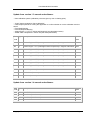
1
User Manual Multi Controller
The TRC Multi Controller USER MANUAL
for connecting Switches / Servos / LEDs
Version 1.7 – 7 April 2009
The perfect controller board for building your cockpit
Connect up to 736 hardware devices to Microsoft Flight Simulator
using Multi Controllers and choose out of 1100 different instruments/indicators
or other type of Input/Output devices !
Includes Project Magenta Codes
Copyright TRC Development 2007 – version 1.6 – 5 November 2007
Page 1
User Manual Multi Controller
Update from version 1.3 manual and software:
- New calibration system (calibration points are given by user in floating point)
- "Apply" button renamed to "Save calibration"
- User will prompted when closing the application to confirm whether or not the calibration must be
saved.
- Fixed Stall Warning
- Fixed Overspeed Warning
- Added Engine 1 / 4 ITT in celcius and fahrenheir (see description below)
- Added Cabin Temperature / Climb / Alt (see description below)
TRC
Type Description
Code
FSUIPC
Code
443
S
Turbine Engine 1 ITT (interstage turbine temperature) in degrees Celcius
2038
444
S
Turbine Engine 1 ITT (interstage turbine temperature) in degrees Fahrenheit 2038
445
S
Turbine Engine 2 ITT (interstage turbine temperature) in degrees Celcius
446
S
Turbine Engine 2 ITT (interstage turbine temperature) in degrees Fahrenheit 2138
447
S
Turbine Engine 3 ITT (interstage turbine temperature) in degrees Celcius
448
S
Turbine Engine 3 ITT (interstage turbine temperature) in degrees Fahrenheit 2238
449
S
Turbine Engine 4 ITT (interstage turbine temperature) in degrees Celcius
450
S
Turbine Engine 4 ITT (interstage turbine temperature) in degrees Fahrenheit 2338
904
S
Cabin Temperature (factor 0.1)
567E
905
S
Cabin Climb (factor 10)
56A4
906
S
Cabin Alt (factor 10)
56A6
2138
2238
2338
Update from version 1.4 manual and software:
TRC Type
Code
Description
FSUIPC
Code
907
S
APU-EGT
5604
908
S
BleedPSI1 (Duct Press 1)
567A
909
S
BleedPSI2 (Duct Press 2)
567C
910
S
CabinDiffPress
56B8
Copyright TRC Development 2007 – version 1.6 – 5 November 2007
Page 2
User Manual Multi Controller
Contents
1. TRC programmable Multi Controller .................................................................................................. 5
2. The control software .......................................................................................................................... 8
C. The Multi Controller driver software mclink.exe............................................................................. 9
3. Installing the software ...................................................................................................................... 10
4. Connecting the Multi Controller to your PC for the first time ........................................................... 13
5. Using the Multi Controller “Number Assign” program: mcnum.exe. ................................................ 15
Step 4 – IMPORTANT! ..................................................................................................................... 16
6. About the I/O line assign and calibration software (mccal.exe) ...................................................... 17
PM codes * ....................................................................................................................................... 17
7. Using the I/O assign and calibration software mccal.exe................................................................ 18
WARNING ! ! ! ..................................................................................................................................... 20
8. Calibration of connected Gauges (servos) ...................................................................................... 21
Example 1: Calibrating a Vertical Speed Indicator .......................................................................... 22
Example 2: Calibrating a 450 knots Airspeed Indicator .................................................................. 23
Example 3: calibrating a Flaps Indicator ......................................................................................... 24
9. Using the MC Link program ............................................................................................................. 25
10. Table of I/O possibilities based on FSUIPC codes ....................................................................... 26
11. Table of I/O possibilities based on Project Magenta codes – table 1 ........................................... 36
12. Table of I/O possibilities based on Project Magenta codes / Table 2 ........................................... 43
13. How to connect instruments to the I/O lines of the Multi Controller .............................................. 53
14. Hardware pin assignment of the Multi Controller .......................................................................... 54
15. How to connect Switches, LED’s and Gauges (Servos) correctly ................................................ 54
16. Schematics .................................................................................................................................... 55
17. Multi Controller Connector Table ................................................................................................... 57
18. Available expansion boards for the Multi Controller ...................................................................... 58
The “Screw Terminal” expansion board ................................... Fout! Bladwijzer niet gedefinieerd.
19. Additional important information .................................................................................................... 59
Important: Please read the remark on assigning a sequence number to the Multi Controller in
Chapter 3 and 5 prior to connecting any Multi Controller to your USB port!!!
This manual and the software to control the Multi Controller are copyrighted by TRC Development b.v.
Nothing from this manual may be used, published or otherwise copied without prior written approval from
TRC Development b.v. – The Netherlands.
Copyright TRC Development 2007 – version 1.6 – 5 November 2007
Page 3
User Manual Multi Controller
Original Publish date: August 1, 2005
Copyright TRC Development 2007 – version 1.6 – 5 November 2007
Page 4
User Manual Multi Controller
1. TRC programmable Multi Controller
No programming knowledge necessary!
The TRC programmable “Plug-and-Play” Multi Controller is a USB connected I/O board offering 23
Input/Output lines. Each I/O line is capable of a.) driving an LED (Light Emitting Diode, max. 20 mA),
b.) driving a servo motor, or c.) reading the position of a switch.
You choose the function of each I/O line. Each line contains three connectors (input connector, output
connector and servo connector). These lines may be used to control many different flight simulator
functions.
The Multi Controller can control single or dual pointer gauges. It cannot control gauges which need to
feed back positioning signals to the controller, like the Altimeter, Heading Indicator, VOR1/2, ADF or
Wet Compass. Therefore you need to use a CCU or SIC board.
When using already a CCU or SIC, you can use Multi Controller(s) to expand your cockpit to even a 6
engine aircraft with many, many additional gauges, switches or LED signals.
The Multi Controller software (included with the controller board) uses the I/O system from the FSUIPC
software (written by Pete Dowson) to connect to Microsoft Flight Simulator. This PC compatible
software is capable of recognizing up to 32 Multi Controllers connected to the PC via a single USB
cable, thereby creating the most advanced control system for flight simulation ever (multiple USB
devices can be connected by daisy chaining USB hubs).
The version 1.3 release of the Multi Controller software does support Project Magenta (see
www.projectmagenta.com) codes (see tables).
Note: A separate license is required in order to use FSUIPC software to connect MS Flight Simulator to
Project Magenta. Contact www.schiratti.com/dowson.html to obtain the necessary license.
No programming knowledge is required. To assign an instrument or a function to an Input/Output line,
merely select the instrument or function from a list of over 250 possibilities!
You may assign one I/O line drive an LED, another to drive a servo motor on a SimKits instrument, and
a third to read the position of a switch. You have unlimited possibilities with the new TRC programmable
Multi Controller.
By adding one or more inexpensive USB hubs to your PC, you may connect up to 32 of these
controllers to your PC. This will allow the connection of up to 736 instruments, 736 switches, 736 LED’s
Copyright TRC Development 2007 – version 1.6 – 5 November 2007
Page 5
User Manual Multi Controller
(outputs) to your PC (or a combination thereof), thus allowing nearly limitless possibilities in simulator
configuration!
The TRC programmable Multi Controller uses the same proven technical architecture as the Central
Control Unit (CCU), and may be the ultimate solution for designing your cockpit!
To drive servos or multiple LED’s, you will need to connect a standard PC power supply to the power
connector on the board. Should you use the board to “read” inputs only (like switches), the power
supplied via the USB cable is sufficient, since this drives the electronics on the board only. You can
connect a maximum of 23 different instruments to each Multi Controller (one per I/O line).
Note: If using multiple “daisy chained” hubs, it is highly recommended to use powered hubs, since the
output of a PC can normally deliver a maximum of 500mA.
For example, should you use a single Multi Controller and assign all the outputs to drive LED’s (20mA
each), power consumption from the USB is approximately 480mA when a separate power supply is not
used. This is approximately the maximum output available from a USB connection.
However, if you connect an external PC power supply to the Multi Controller and configure the jumpers
so that this external power is used to drive the LED’s etc., you will not need powered hubs when
connecting only a few (up to 10) Multi Controllers.
OUTPUT
Each I/O line can be configured as an Output. You can connect an LED to this line via a current limiting
resistor, or you may connect a small relay to drive heavier electric loads. The maximum current output
per I/O line is 20mA. An LED in combination with a current limiting resistor uses less than 20mA.
Note: The current limiting resistor is already mounted on the Multi Controller.
Then by using the included software, you assign this output of the Multi Controller to a certain function
in Microsoft Flight Simulator (ie. panel lights).
INPUT
Each I/O line can also be configured as an Input. You can then connect one side of a switch to this I/O
line and connect the other side of the switch to ground (available on the I/O connector). Then by again
using the included software, you assign this switch to a function in Microsoft Flight Simulator (ie.
avionics on/off).
Copyright TRC Development 2007 – version 1.6 – 5 November 2007
Page 6
User Manual Multi Controller
SERVO
Each I/O line can also be configured to drive a servo to control a pointer on an instrument, such as the
needle on the manifold pressure gage. You will need to connect a standard PC power supply to the
Multi Controller board and place a jumper into the correct position (see block schematics) in order to
feed this external power to the servo.
The software used to control the setting of the TRC programmable Multi Controller has an easy “click
and assign” interface. This enables you – without programming knowledge – to assign the function of
each I/O line to an instrument or other function within Microsoft Flight Simulator via the FSUIPC
interface software.
Copyright TRC Development 2007 – version 1.6 – 5 November 2007
Page 7
User Manual Multi Controller
2. The control software
To use the Multi Controller board and to assign a certain I/O line to a function in Microsoft Flight
Simulator, no programming knowledge is necessary. All configurations are “Click-and-Assign”.
The Multi Controller software uses FSUIPC to connect to Microsoft Flight Simulator. This program can
be downloaded from the website http://www.schiratti.com/dowson.html. The FSUIPC installation
documentation and users manual may be downloaded from this site, also.
The Multi Controller needs three (3) different software programs to function:
A. The Multi Controller “number assign” program: mcnum.exe
B. The I/O assign and calibration software: mccal.exe
C. The Multi Controller Driver software: mclink.exe
A. The Multi Controller “number assign” program mcnum.exe
The first activity is to assign an identity to each Multi Controller card. This number is “programmed”
once into an on-board EEPROM (electrically erasable programmable ROM), and will remain there
unless you use the software again to re-program the number. Therefore, this software is normally only
used once to initially identify each Multi Controller.
Note: Each Multi Controller comes from the factory assigned as a “number 1 device”, and multiple
controllers must be renumbered.
Very Important: When connecting a Multi Controller to your PC to be
renumbered, this must be the only controller connected at this time.
Otherwise the mcnum.exe program isn’t able to distinguish which
controller you wish to re-number! So therefore disconnect any Simkits
USB devices like the CCU, SIC, Radio Stack Controller or other Multi
Controllers before you start the mcnum.exe program!!
Once this unique number/identification is assigned to the Multi Controller, the driver software will
recognize it. If using only one Multi Controller, you don’t have to assign a number to the board, although
you may wish to do so to become familiar with the mcnum.exe software.
The Multi Controller may be connected either directly to a USB port on your computer or through a USB
hub, which may be purchased from the SimKits website or from a local computer shop.
Copyright TRC Development 2007 – version 1.6 – 5 November 2007
Page 8
User Manual Multi Controller
As each Multi Controller requires only 50mA to function, many boards may be connected to a single
USB port by using non-powered hubs. However, if powering a multitude of LED’s and servos, it is
recommended to use a PC power supply so as to not overload the USB source.
B. The I/O assign and calibration software mccal.exe
With the Multi Controller board(s) connected to your PC and the “assign and calibration” software
installed, you may begin assigning each I/O line to a certain function in Microsoft Flight Simulator or to
Project Magenta. Complete instructions on how to assign and calibrate the instruments connected to a
Multi Controller are found in Chapter 5.
C. The Multi Controller driver software mclink.exe
This software connects to Microsoft Flight Simulator via the FSUIPC software from Pete Dowson (see
www.schiratti.com/dowson.html for more information). You will need FSUIPC version 3.xx or later.
The mclink.exe software uses the data produced by the mccal.exe software to control each I/O line and
the function assigned to it.
Note: When the mclink.exe program is running, the mcnum.exe and mccal.exe programs should be
closed.
Copyright TRC Development 2007 – version 1.6 – 5 November 2007
Page 9
User Manual Multi Controller
3. Installing the software
Note: Do not connect the Multi Controller(s) to your PC yet.
In order to download the required files, you must first create a directory in which to store the files (such
as a directory named “Multicontroller”). Then download the file “Multicontroller.zip” from the Simkits
website [email protected] and unzip the file into this directory. Verify that you are downloading the
latest version of the software, and periodically go to the website and download any updates that may be
available.
The zip file contains the following files:
Setup.exe
trcmc.inf
trcdrv.sys
Close all open programs and start the program Setup.exe.
Now follow the on-screen directions to install
the software program.
Copyright TRC Development 2007 – version 1.6 – 5 November 2007
Page 10
User Manual Multi Controller
If you agree with the directory chosen by the
software installation program, just click
“Next”.
Otherwise, browse for a new directory of
your choice.
(The list of “Existing Folders” on the left
is only an example, and is different from
the list that will be seen on your
computer!)
Copyright TRC Development 2007 – version 1.6 – 5 November 2007
Page 11
User Manual Multi Controller
When the installation is done, click “Finish”
to restart your computer. This will save the
new settings.
Copyright TRC Development 2007 – version 1.6 – 5 November 2007
Page 12
User Manual Multi Controller
4. Connecting the Multi Controller to your PC for the first time
Once you have installed the Multi Controller software, you may now connect the Multi Controller
board(s) to your PC using the included USB
cable. Your PC will recognize the Multi
Controller as a new device and the following
screens will be shown:
Select “No, not this time” and click “Next”.
Now click on the option “Install from a
specific location (Advanced)” and click
“Next”.
Use the “Browse” option and choose the
directory into which you unzipped the
downloaded software.
This directory should contain the files
“trcdrv.sys” and “trcmc.inf”.
Now click “Next”.
Copyright TRC Development 2007 – version 1.6 – 5 November 2007
Page 13
User Manual Multi Controller
The “Found New Hardware Wizard” will
start installing the driver software.
This process may take several minutes.
While the software is installing the driver,
you will see the progress of the installation
in the window on the screen.
Once the driver is installed, press the
“Finish” button to finalize the installation.
Your PC may ask for a restart. If it does,
restart your PC.
Then follow the directions in the next
Chapter.
Copyright TRC Development 2007 – version 1.6 – 5 November 2007
Page 14
User Manual Multi Controller
5. Using the Multi Controller “Number Assign” program: mcnum.exe.
The Multi Controller is delivered from the factory with the internal number set to 1. This means that
should you have more than one Multi Controller connected to your PC, they would all look the same to
your PC, and the software would not be able to recognize them from each other.
Therefore, TRC has developed the “Number Assign” program, called mcnum.exe. This program allows
you to assign a number (from 1 to 32) to each Multi Controller.
Very Important: When connecting a Multi Controller to your PC to be
renumbered, this must be the only controller connected at this time.
Otherwise the mcnum.exe program isn’t able to distinguish which
controller you wish to re-number! So therefore disconnect any Simkits
USB devices like the CCU, SIC, Radio Stack Controller or other Multi
Controllers before you start the mcnum.exe program!!
Step 1
Disconnect all Multi Controllers from your PC except the one you are renumbering.
Step 2
Start the Multi Controller number assign program mcnum.exe. The following screen is shown:
Step 3
Arrow down to the number you would like to assign to this specific Multi Controller board and press
“Program”. You will automatically be asked to “verify” your selection, which will result in a message
being displayed in the lower part of the window informing you about the results of the program action.
Copyright TRC Development 2007 – version 1.6 – 5 November 2007
Page 15
User Manual Multi Controller
To verify that the number has been correctly assigned to the Multi Controller, connect the controller to
your PC (note: only 1 at a time) and press “Verify”. This will result in a message in the lower part of the
screen informing you which number has been programmed into this particular controller
Note: the field Multi Controller ID does not necessarily tell you the correct number of the Multi Controller
when using the “verify” function, only the status line does!
Step 4 – IMPORTANT!
You must now temporarily disconnect the USB cable from the Multi Controller. Otherwise, your PC will
not recognize the newly assigned number, and will be looking for the old number that was assigned to
the controller prior to programming the new identity. Just unplug the USB cable, wait 5 seconds and
plug it in again. Your PC will now recognize the controller as a new device.
Once the PC has recognized the new device, you can use it with the I/O assign and calibration
software: mccal.exe.
Copyright TRC Development 2007 – version 1.6 – 5 November 2007
Page 16
User Manual Multi Controller
6. About the I/O line assign and calibration software (mccal.exe)
This software program finally connects the Multi Controller to Microsoft Flight Simulator. As mentioned
previously, you will also need the latest version of the FSUIPC software to control the standard list of
instruments that are currently available to Microsoft Flight Simulator and/or Project Magenta, as well as
to control additional instruments as they become available. For more information on the FSUIPC
software, please consult www.schiratti.com/dowson.html.
The following list of codes depicts the general numbering system assigned to the I/O lines.
The first groups of codes are FSUIPC (Flight Simulator) codes, while the second group is for Project
Magenta.
Please note: The numbers used by the Multi Controller software are not necessarily identical to the
FSUIPC or Project Magenta codes. Each function has been assigned a unique number for ease of
assigning functions.
FSUIPC codes
The numbers 100 through 199 are reserved for Inputs
The numbers 200 through 299 are reserved for Outputs
The numbers 300 through 399 are reserved for Servos (gauges)
PM codes *
The numbers 600 through 799 are reserved for Inputs
The numbers 800 through 899 are reserved for Outputs
The numbers 900 through 999 are reserved for Servos (gauges)
Copyright TRC Development 2007 – version 1.6 – 5 November 2007
Page 17
User Manual Multi Controller
7. Using the I/O assign and calibration software mccal.exe
Even though you may have previously connected a Multi Controller to your PC, after using the Number
Assign program (mcnum.exe), the identification of the Multi Controller has been changed and is
therefore viewed as a new item to your PC. You may need to repeat the steps in Chapter 4 to correct
any errors in assignments.
When you use a new Multi Controller for the first time with the I/O assign and calibration software, there
are no functions assigned to any of the I/O lines. With a previously used controller, the chart will show
all assigned functions in their specific fields.
If you are not satisfied with the assignment of an I/O line or the response of a gauge, you may wish to
run the mccal.exe software program again. Only the latest changes produced by running mccal.exe are
saved into the parameter files.
See the following pages for directions on using the mccal.exe program.
Copyright TRC Development 2007 – version 1.6 – 5 November 2007
Page 18
User Manual Multi Controller
Multi Controller Calibration Centre
The Multi Controller field identifies the
Multi Controller you are working on. If
the dropdown list doesn’t show the
number of a particular controller, then
the mccal.exe software has not
recognized that controller.
Address
Enter the number of the desired function
from the list of possible I/O functions (in
the column TRC#)
The mccal.exe program recognizes the
type of function you have chosen and
enters it for you.
Type
Here the mccal.exe program displays
the type of function you have chosen:
Servo to drive a gauge, Input to read
from a switch and Output to drive an
LED or other device.
Function
Short description of the function that is
assigned to this I/O line.
Calibrate
Press this button (when available) to
calibrate the gauge.
Save Calibration
Press this button to save the settings.
Up to 23 I/O lines per Multi Controller
The fields are numbered from 1 to 23. By entering the appropriate number from the list from Chapter 10
or 11, you have assigned a certain function to that I/O line of the Multi Controller.
When the function is an Output, you don’t have to do anything anymore to complete this function. The
output will respond to the high or low signal from Microsoft Flight Simulator or from Project Magenta. An
LED can be directly connected to the I/O line, which may draw a maximum of 20mA. A current limiting
resistor has been placed on the Multi Controller to prevent drawing excessive current. A DIL relay
operating at 5V, 20mA may be connected to switch heavier loads.
See technical details in Chapters 12 through 16 for connecting LED’s.
Copyright TRC Development 2007 – version 1.6 – 5 November 2007
Page 19
User Manual Multi Controller
When the function is an Input, connect a switch or a pushbutton to this I/O line. Closing the switch will
cause the input to be recognized by Microsoft Flight Simulator or to Project Magenta.
See technical details in Chapters 12 to 16 for connecting switches.
When the function is a Servo, you need to connect a gauge with a servo to this I/O line. The “Calibrate”
button now becomes active, and you can calibrate the gauge as described on the following pages.
See technical details in Chapters 12 to 16 for connecting servos. And don’t forget to connect an
external power supply to the Multi Controller to drive the servos!
WARNING ! ! !
When the calibration is started for the first time for a Multi Controller Board
which you have not used to calibrate earlier (you clicked on the button
“Calibrate”), the Multi Controller is recognized as a new USB device.
Therefore you must follow once again the steps as described in Chapter 4 on
page 10 and 11.
Fail to do so, will cause that you cannot use the Multi Controller as you wish.
This extra USB installation/identification towards Windows is only necessary
once.
Copyright TRC Development 2007 – version 1.6 – 5 November 2007
Page 20
User Manual Multi Controller
8. Calibration of connected Gauges (servos)
Since servo motors are used in the gauges, they each need to be calibrated once before using them
with Microsoft Flight Simulator, because most of the face plate scales used in aircraft are non-linear.
Therefore, the software must “learn” about the scale being used, and will save the created data into a
file. The file data is used by the program mclink.exe, which controls the instrument connected to the I/O
line. Needless to say, you must have a gauge connected to this I/O line.
The first step of the calibration
By clicking on the calibration button in the previous screen, you
entered the calibration routine for a certain instrument.
Function
Here the TRC number selected from the list is shown again for
security.
Also, the function description is show again.
Initiate the values
The screen shows 10 input fields and 10 sliders, each
numbere from “Step 1” to “Step 10”.
Here you have to enter the values you see on the faceplate of
the gauge. In case there are less than 10 values on the gauge
faceplate, you need to devide the faceplate into imaginary
values. For example, your faceplate only shows 10, 30, 50, 70,
90, you need to find out where values 0, 20, 40, 60 and 80
would be. Now you enter the value “0” (zero) in the first field,
20 in the second field, 30 in the third field and so on. It might
be necessary to do some calculations here when you have a
faceplate which has a non-linear scale other than a linear
scale. Some try and error will help you to get there!
In case your scale calculation doesn’t come out to exactly 10
values, you may use a value double. Fore xample when the
last value is 100 and you have reached that value in field 9,
you may enter the value 100 also in field 10.
Note
When you want to calibrate a gauge like a Vertical Speed Indicator, you will need to enter negative
values (for example -20, -15, -10, -5, 0, 0, 5, 10, 15, 20)
Copyright TRC Development 2007 – version 1.6 – 5 November 2007
Page 21
User Manual Multi Controller
Example 1: Calibrating a Vertical Speed Indicator
When calibrating a vertical speed indicator, you need to enter negative as well as positive values in the
Value Fields.
Always start to calibrate clockwise. This means that you must
enter the lowest (or most negative) value in the first field and
then the next higher (or less negative) value in the subsequent
fields.
Prior to entering these values, you should check whether you
come to an odd or even amount of values.
In case (as with the VSI) the number of values are odd, you need
to enter a certain value twice. In this case the value “0” (zero)
needs to be entered twice.
Now use the slider to calibrate the pointer exactly to the position
as in the value field given.
For the zero value (entered twice) you have to set the pointer
indeed for both “zeros”, precisely at “0”.
Important:
During calibration, the pointer must always be set clockwise to a
new position. Moving the pointer from –20 to +20 the shortest
way will give a wrong calibration! When constructin a kit gauge,
you should always be sure that the pointer can reach all
positions on the faceplate and has some “spare” available on
both ends of the scale.
I
Copyright TRC Development 2007 – version 1.6 – 5 November 2007
Page 22
User Manual Multi Controller
Example 2: Calibrating a 450 knots Airspeed Indicator
This example uses a 450 knots Airspeed indicator scale as used
in an Airliner.
The Airliner ASI scale is partly linear and partly non-linear.
Therefore you can set the calibration values for the linear part of
the scale in such a way, that the values are in larger steps than
the non-linear part.
This example has set the values in such a way, that a proper
division between the linear and non-linear values gives the best
results.
These values are:
0, 70, 100, 130, 170, 210, 240, 250, 300, 400.
Important:
During calibration, the pointer must always be set clockwise to a
new position. Moving the pointer from 0 to 400 the shortest way
will give a wrong calibration! When constructin a kit gauge, you
should always be sure that the pointer can reach all positions on
the faceplate and has some “spare” available on both ends of the
scale.
Copyright TRC Development 2007 – version 1.6 – 5 November 2007
Page 23
User Manual Multi Controller
Example 3: calibrating a Flaps Indicator
This example uses a Flaps indicator scale as used in an Airliner .
As the calibration is based on dividing the scale of the gauge into the proper values which come from
the flight simulator software, first you have to divide the scale (faceplate) of the gauge into sections from
0 to 100%.
The scale has the following values:
UP (0), 1, 2, 5, 10, 15, 25, 30, 40
As the full path of the pointer - from UP(0) to 40 - has
to be divided on the scale as from 0 to 100%, the
following table is created:
Scale values
% of scale
UP(0)
0
1
2.5
2
5
5
7.5
10
25
15
37.5
25
62.5
30
75
40
100
Since the calibration table cannot handle
fractions, the values behind the decimal
point are rounded off.
Since there are only 9 values, the last value
is repeated in step 10 (100 entered)
The calibration has to be carried out for
each individual pointer.
Copyright TRC Development 2007 – version 1.6 – 5 November 2007
Page 24
User Manual Multi Controller
9. Using the MC Link program
Once you have “identified” the Multi Controller board using the mcnum program (you should always
assign a number to a Multi Controller, even if using only one) and once you have properly calibrated
each controller you have connected, you can use the program mclink to “connect” the hardware (via
FSUIPC) to Microsoft Flight Simulator.
As a reminder, the use of the Multi Controller requires three programs: first, the mcnum.exe program to
assign a number to the Multi Contoller; second, the mccal.exe program to assign the proper instrument
to the Multi Controller and to calibrate it (calibration only needed for gauges), and third, the mclink.exe
program to “connect” the hardware via FSUIPC to Microsoft Flight Simulator.
For each Multi Controller connected to your PC, you have to run the mclink.exe program.
For example, when you have three Multi Controllers connected via USB to your computer, you should
run the mclink.exe program three times. However, there will be a different number in the number field
each time. In the example shown, the program shows number 1 in the entry field. The next running of
the program should show a different number.
You can assign and start up to 32 Multi Controllers this way. The actual order you use doesn’t matter as
long as you run the program for each Multi Controllers connected to your PC.
Message
The MC Link window also tells you when the Flight Simulator software is connected, when the Multi
Controller is connected, or when the ID is already occupied. The MC Link ID field always defaults to the
number one (1). Therefore, if you have previously connected a Multi Controller with an MCLink, at the
startup of the next one, the message “Already Occupied” will be displayed, meaning that you have to
select a different number. The possible messages are:
“Already Occupied” (when number 1, for example, is already in use)
“Not Connected” (when for any reason the software cannot connect to a Multi Controller)
“Connected” (when the software is properly connected to a Multi Controller).
Copyright TRC Development 2007 – version 1.6 – 5 November 2007
Page 25
User Manual Multi Controller
-
-
Alternator (1 = on, 0 = off), read for state, write to
FSUIPC #
Description
Functional
Units
-
Value
Minimum
I
Maximum
Type
101
Value
TRC #
10. Table of I/O possibilities based on FSUIPC codes
3101
control [FS2000+]
102
I
-
-
-
Avionics (1 = on, 0 = off), read for state, write to
3103
control [FS2000+]
103
I
-
-
-
Battery (1 = on, 0 = off), read for state, write to
3102
control [FS2000+]
104
I
-
-
-
Rotating Beacon
0D0C
105
I
-
-
-
Cabin Lights
0D0C
106
I
-
-
-
Engine 1 Anti-Ice or Carb Heat switch (1=On)
08B2
107
I
-
-
-
Engine 1 Fuel Valve, 1 = open, 2 = closed. Can write
3590
108
I
-
-
-
109
I
-
-
-
Engine 1 Magnetos (Both)
0892
110
I
-
-
-
Engine 1 Magnetos (Left)
0892
111
I
-
-
-
Engine 1 Magnetos (Right)
0892
112
I
-
-
-
Engine 1 Magnetos (Start)
0892
113
I
-
-
-
Engine 2 Anti-Ice or Carb Heat switch (1=On)
094A
114
I
-
-
-
Engine 2 Fuel Valve, 1 = open, 2 = closed. Can write
3594
115
I
-
-
-
116
I
-
-
-
Engine 2 Magnetos (Both)
117
I
-
-
-
Engine 2 Magnetos (Left)
092A
118
I
-
-
-
Engine 2 Magnetos (Right)
092A
119
I
-
-
-
Engine 2 Magnetos (Start)
092A
120
I
-
-
-
Engine 3 Anti-Ice or Carb Heat switch (1=On)
0900
121
I
-
-
-
Engine 3 Fuel Valve, 1 = open, 2 = closed. Can write
3598
122
I
-
-
-
123
I
-
-
-
Engine 3 Magnetos (Both)
09C2
124
I
-
-
-
Engine 3 Magnetos (Left)
09C2
125
I
-
-
-
Engine 3 Magnetos (Right)
09C2
126
I
-
-
-
Engine 3 Magnetos (Start)
09C2
127
I
-
-
-
Engine 4 Anti-Ice or Carb Heat switch (1=On)
0A7A
128
I
-
-
-
Engine 4 Fuel Valve, 1 = open, 2 = closed. Can write
359C
to operate. [FS2002+]
Engine 1 generator switch, a 32-bit BOOL (0 = off,
3B78
1= on) [FS2000-FS2004 only]
to operate. [FS2002+]
Engine 2 generator switch, a 32-bit BOOL (0 = off,
3AB8
1= on) [FS2000-FS2004 only]
092A
to operate. [FS2002+]
Engine 3 generator switch, a 32-bit BOOL (0 = off,
39F8
1= on) [FS2000-FS2004 only]
to operate. [FS2002+]
Copyright TRC Development 2007 – version 1.6 – 5 November 2007
Page 26
-
-
Engine 4 generator switch, a 32-bit BOOL (0 = off,
FSUIPC #
Description
Functional
Units
-
Value
Minimum
I
Maximum
Type
129
Value
TRC #
User Manual Multi Controller
3938
1= on) [FS2000-FS2004 only]
130
I
-
-
-
Engine 4 Magnetos (Both)
0A5A
131
I
-
-
-
Engine 4 Magnetos (Left)
0A5A
132
I
-
-
-
Engine 4 Magnetos (Right)
0A5A
133
I
-
-
-
Engine 4 Magnetos (Start)
0A5A
134
I
-
-
-
Engine primer (just write a non-zero byte to operate
3100
the primer. This is a one-shot and reading it is
meaningless) [FS2000+]
135
I
-
-
-
Fail mode: 0 ok, Engine inoperable = 1, extended for
0B6B
FS2000/CFS2 for up to 4 individual engines: bit 0
=Engine 1 ... bit 3= Engine 4. (but note that this may
not work for FS98 aircraft transposed into
FS2k/CFS2).
136
I
-
-
-
Fail mode: ADF
0B64
137
I
-
-
-
Fail mode: Altimeter
0B66
138
I
-
-
-
Fail mode: ASI
0B65
139
I
-
-
-
Fail mode: Attitude Indicator
0B67
140
I
-
-
-
Fail mode: COM1 radio
0B68
141
I
-
-
-
Fail mode: Direction Indicator
0B6D
142
I
-
-
-
Fail mode: Electronics
0B6A
143
I
-
-
-
Fail mode: Fuel indicators
0B6C
144
I
-
-
-
Fail mode: Mag Compass
0B69
145
I
-
-
-
Fail mode: NAV radios
0B70
-
-
146
I
-
147
I
-
148
I
-
149
I
-
-
-
Fail mode: Pitot
0B71
Fail mode: Transponder
0B6F
Fail mode: Turn co-ordinator
0B72
Fail mode: Vacuum
0B73
150
I
-
-
-
Fail mode: VSI
0B6E
151
I
-
-
-
Fuel pump (1 = on, 0 = off), read for state, write to
3104
control [FS2000+]. For separate switches for
separate fuel pumps see offset 3125.
152
I
-
-
-
Fuel tank selector: All
0AF8
153
I
-
-
-
Fuel tank selector: Centre
0AF8
154
I
-
-
-
Fuel tank selector: Centre 2
0AF8
155
I
-
-
-
Fuel tank selector: Centre 3
0AF8
156
I
-
-
-
Fuel tank selector: Crossfeed LtoR
0AF8
157
I
-
-
-
Fuel tank selector: Crossfeed RtoL
0AF8
158
I
-
-
-
Fuel tank selector: External 1
0AF8
159
I
-
-
-
Fuel tank selector: External 2
0AF8
160
I
-
-
-
Fuel tank selector: Left
0AF8
161
I
-
-
-
Fuel tank selector: Left Tip
0AF8
Copyright TRC Development 2007 – version 1.6 – 5 November 2007
Page 27
FSUIPC #
Description
Functional
Units
Value
Maximum
Value
Minimum
Type
TRC #
User Manual Multi Controller
162
I
-
-
-
Fuel tank selector: Left Aux
0AF8
163
I
-
-
-
Fuel tank selector: Right
0AF8
164
I
-
-
-
Fuel tank selector: Right Tip
0AF8
165
I
-
-
-
Fuel tank selector: Right Aux
0AF8
166
I
-
-
-
Gear control
0BE8
167
I
-
-
-
Instruments
0D0C
168
I
-
-
-
Landing Light
0D0C
169
I
-
-
-
Logo
0D0C
NAV/GPS switch, in FS2000 & FS2002. 0=NAV,
132C
170
I
-
-
-
171
I
-
-
-
172
I
-
-
-
173
I
-
-
-
174
I
-
-
-
175
I
-
-
-
176
I
-
-
-
177
I
-
-
-
178
I
-
-
-
Panel auto-feather arm switch (0=Off, 1=On)
179
I
-
-
-
Parking brake
0BC8
180
I
-
-
-
Pause MS-Flightsimulator
0262
1=GPS
Navigation Lights
PANEL AUTOBRAKE SWITCH Read to check
setting, write to change it. Brake1
PANEL AUTOBRAKE SWITCH Read to check
setting, write to change it. Brake2
PANEL AUTOBRAKE SWITCH Read to check
setting, write to change it. Brake3
PANEL AUTOBRAKE SWITCH Read to check
setting, write to change it. max
PANEL AUTOBRAKE SWITCH Read to check
setting, write to change it. RTO
PANEL AUTOBRAKE SWITCH Read to check
setting, write to change it.Off
0D0C
2F80
2F80
2F80
2F80
2F80
2F80
2E88
181
I
-
-
-
Pitot Heat switch
029C
182
I
-
-
-
Prop sync active (1=Active, 0=Inactive)
2EC8
Propeller de-ice switch, (1 = on, 0 = off), read for
state, write to control [FS2002+]. This should
183
I
-
-
-
operate with aircraft defined to have the facility, but
337C
in fact it merely reflects the older Anti-Ice switch. The
TOGGLE_PROP_DEICE control does nothing.
184
I
-
-
-
Recognition
0D0C
185
I
-
-
-
Spoilers arm (0=off, 1=arm for auto deployment)
0BCC
186
I
-
-
-
Strobes
0D0C
Structural de-ice switch, (1 = on, 0 = off), read for state,
write to control [FS2002+]. Although this is documented in
187
I
-
-
-
both FS2002 and FS2004 panel SDKs, with a token value
and an FS control, it appears to do nothing. Possibly it
337D
needs some action in the AIR file or Aircraft.CFG, but
there's nothing in the official documentation.
188
I
-
-
-
Taxi
Copyright TRC Development 2007 – version 1.6 – 5 November 2007
0D0C
Page 28
3B7C
-
-
201
O
-
-
-
Value
I
FSUIPC #
Functional
Engine 1 generator active, a 32-bit BOOL (0 = off,
189
Value
Description
Units
0D0C
Minimum
Wing
Type
-
TRC #
Maximum
User Manual Multi Controller
1= on) [FS2000-FS2004 only]
202
O
-
-
-
Engine 2 generator active, a 32-bit BOOL (0 = off,
3ABC
1= on) [FS2000-FS2004 only]
203
O
-
-
-
Engine 3 generator active, a 32-bit BOOL (0 = off,
39FC
1= on) [FS2000-FS2004 only]
204
O
-
-
-
Engine 4 generator active, a 32-bit BOOL (0 = off,
393C
1= on) [FS2000-FS2004 only]
205
O
-
-
-
Gear busy indicator
0BE8/
0BEC/
0BF0/
0BF4
206
O
-
-
-
Gear down indicator
0BEC/
0BF0/
0BF4
207
O
-
-
-
Gear position (left)
0BF4
208
O
-
-
-
Gear position (nose)
0BEC
209
O
-
-
-
Gear position (right)
0BF0
210
O
-
-
-
Indicator if airplane is on ground
0366
211
O
-
-
-
Inner Marker: activated when TRUE
0BAC
212
O
-
-
-
Middle Marker: activated when TRUE
0BAE
213
O
-
-
-
Outer Marker: activated when TRUE
0BB0
214
O
-
-
-
Overspeed warning
036D
215
O
-
-
-
Stall warning
036C
216
O
-
-
-
"This byte reflects the FS2004 ""Engine on Fire""
3366
flags. I'm not sure if FS actually simulates such
events, but it appears to have allocated Gaugeaccessible variables to indicate them. Engine 1"
217
O
-
-
-
"This byte reflects the FS2004 ""Engine on Fire""
3366
flags. I'm not sure if FS actually simulates such
events, but it appears to have allocated Gaugeaccessible variables to indicate them. Engine 2"
218
O
-
-
-
"This byte reflects the FS2004 ""Engine on Fire""
3366
flags. I'm not sure if FS actually simulates such
events, but it appears to have allocated Gaugeaccessible variables to indicate them. Engine 3"
Copyright TRC Development 2007 – version 1.6 – 5 November 2007
Page 29
-
-
"This byte reflects the FS2004 ""Engine on Fire""
FSUIPC #
Description
Functional
Units
-
Value
Minimum
O
Maximum
Type
219
Value
TRC #
User Manual Multi Controller
3366
flags. I'm not sure if FS actually simulates such
events, but it appears to have allocated Gaugeaccessible variables to indicate them. Engine 4"
220
O
-
-
-
This byte shows doors that are open (FS2004 only).
3367
At present this only provides bit 2^0 for the main
doors.
301
S
Aileron position indicator (maybe adjusted from
0BB8
input!)
302
S
303
S
-90
mach
Airspeed Mach value, double float (FS2002+)
35A0
+90
degrees
Attitude indicator bank value
2F78
304
S
305
S
-25
+25
degrees
Attitude indicator pitch value
2F70
0
33554432
knots
Barber pole airspeed
02C4
306
S
Braking indicator: brake applied if non-zero
0BCA
(16383=on, 0=off). Note that in FS2002 this is
artificially created by FSUIPC from the previous
three settings.
307
S
Elevator position indicator (maybe adjusted from
0BB4
input!)
308
S
-100
+100
Elevator trim indicator (follows input)
0BC2
309
S
0
1000000
Fahrenheit
Engine 1 CHT
08E8
310
S
-18
555538
Celcius
Engine 1 EGT (Celcius)
08BE
311
S
312
1580
Fahrenheit
Engine 1 EGT (Fahrenheit)
08BE
312
S
0
19
gallon/hour
Engine 1 Fuel Flow
0918 /
313
S
0
29826161
psi
Engine 1 Fuel pressure, psi
08F8
314
S
0
1073741824
psi
Engine 1 Hydraulic pressure
08D8
315
S
0
100
%
Engine 1 Hydraulic quantity
08DC
316
S
0
65536
rpm
Engine 1 Jet N1: Tachometer
0898 /
0AF4
08C8
317
S
0
100
%
Engine 1 Jet N2: Turbine RPM %
0896
318
S
0
64
"""Hg"
Engine 1 Manifold Pressure
08C0
319
S
0
220
psi
Engine 1 Oil pressure
08BA
320
S
0
100
%
Engine 1 Oil Quantity
08D0
321
S
-18
38
Celcius
Engine 1 Oil temperature (Celcius)
08B8
322
S
75
284
Fahrenheit
Engine 1 Oil temperature (Fahrenheit)
08B8
323
S
0.0
6.4
-
Engine 1 Pressure Ratio
08BC
324
S
0
100
%
Engine 1 Rotor RPM
0908
325
S
0
100
%
Engine 1 Torque
08F4
326
S
0
262144
psi
Engine 1 Transmission oil pressure
0900
327
S
0
262144
Celcius
Engine 1 Transmission oil temperature
0904
Copyright TRC Development 2007 – version 1.6 – 5 November 2007
Page 30
Functional
4294967296
Celcius
Engine 1 Turbine temperature
08F0
0,0
5,0
-
Engine 1 Vibration
08D4
330
S
0
1000000
Fahrenheit
Engine 2 CHT
0980
331
S
-18
555538
Celcius
Engine 2 EGT (Celcius)
0956
332
S
312
1580
Fahrenheit
Engine 2 EGT (Fahrenheit)
0956
333
S
0
19
gallon/hour
Engine 2 Fuel Flow
09B0
334
S
0
29826161
psi
Engine 2 Fuel pressure, psi
990
335
S
0
1073741824
psi
Engine 2 Hydraulic pressure
0970
336
S
0
100
%
Engine 2 Hydraulic quantity
0974
337
S
0
65536
rpm
Engine 2 Jet N1: Tachometer
0930 /
FSUIPC #
Units
0
S
Value
Minimum
S
329
Maximum
Type
328
Value
TRC #
Description
User Manual Multi Controller
0960
338
S
0
100
%
Engine 2 Jet N2: Turbine RPM %
092E
339
S
0
64
"""Hg"
Engine 2 Manifold Pressure
0958
340
S
0
220
psi
Engine 2 Oil pressure
0952
341
S
0
100
%
Engine 2 Oil Quantity
0968
342
S
-18
38
Celcius
Engine 2 Oil temperature (Celcius)
0950
343
S
75
284
Fahrenheit
Engine 2 Oil temperature (Fahrenheit)
0950
344
S
0.0
6.4
-
Engine 2 Pressure Ratio
0954
345
S
0
100
%
Engine 2 Rotor RPM
09A0
346
S
0
100
%
Engine 2 Torque
098C
347
S
0
262144
psi
Engine 2 Transmission oil pressure
998
348
S
0
262144
Celcius
Engine 2 Transmission oil temperature
099C
349
S
0
4294967296
Celcius
Engine 2 Turbine temperature
0988
350
S
0,0
5,0
-
Engine 2 Vibration
096C
351
S
0
1000000
Fahrenheit
Engine 3 CHT
0A18
352
S
-18
555538
Celcius
Engine 3 EGT (Celcius)
09EE
353
S
312
1580
Fahrenheit
Engine 3 EGT (Fahrenheit)
09EE
354
S
0
19
gallon/hour
Engine 3 Fuel Flow
0A48
355
S
0
29826161
psi
Engine 3 Fuel pressure, psi
0A28
356
S
0
1073741824
psi
Engine 3 Hydraulic pressure
0A08
357
S
0
100
%
Engine 3 Hydraulic quantity
0A0C
358
S
0
65536
rpm
Engine 3 Jet N1: Tachometer
09C8 /
359
S
0
100
%
Engine 3 Jet N2: Turbine RPM %
09C6
360
S
0
64
"""Hg"
Engine 3 Manifold Pressure
09F0
361
S
0
220
psi
Engine 3 Oil pressure
09EA
362
S
0
100
%
Engine 3 Oil Quantity
0A00
09F8
363
S
-18
38
Celcius
Engine 3 Oil temperature (Celcius)
09E8
364
S
75
284
Fahrenheit
Engine 3 Oil temperature (Fahrenheit)
09E8
365
S
0.0
6.4
-
Engine 3 Pressure Ratio
09EC
366
S
0
100
%
Engine 3 Rotor RPM
0A38
367
S
0
100
%
Engine 3 Torque
0A24
Copyright TRC Development 2007 – version 1.6 – 5 November 2007
Page 31
FSUIPC #
Description
Functional
Units
Value
Maximum
Value
Minimum
Type
TRC #
User Manual Multi Controller
368
S
0
262144
psi
Engine 3 Transmission oil pressure
0A30
369
S
0
262144
Celcius
Engine 3 Transmission oil temperature
0A34
370
S
0
4294967296
Celcius
Engine 3 Turbine temperature
0A20
371
S
0,0
5,0
-
Engine 3 Vibration
0A04
372
S
0
1000000
Fahrenheit
Engine 4 CHT
0AB0
373
S
-18
555538
Celcius
Engine 4 EGT (Celcius)
0A86
374
S
312
1580
Fahrenheit
Engine 4 EGT (Fahrenheit)
0A86
375
S
0
19
gallon/hour
Engine 4 Fuel Flow
0AE0
376
S
0
29826161
psi
Engine 4 Fuel pressure, psi
0AC0
377
S
0
1073741824
psi
Engine 4 Hydraulic pressure
0AA0
378
S
0
100
%
Engine 4 Hydraulic quantity
0AA4
379
S
0
65536
rpm
Engine 4 Jet N1: Tachometer
0A60 /
0A90
380
S
0
100
%
Engine 4 Jet N2: Turbine RPM %
0A5E
381
S
0
64
382
S
0
220
"""Hg"
Engine 4 Manifold Pressure
0A88
psi
Engine 4 Oil pressure
0A82
383
S
0
100
%
Engine 4 Oil Quantity
0A98
384
S
-18
38
Celcius
Engine 4 Oil temperature (Celcius)
0A80
385
S
75
284
Fahrenheit
Engine 4 Oil temperature (Fahrenheit)
0A80
386
S
0.0
6.4
-
Engine 4 Pressure Ratio
0A84
387
S
0
100
%
Engine 4 Rotor RPM
0AD0
388
S
0
100
%
Engine 4 Torque
0ABC
389
S
0
262144
psi
Engine 4 Transmission oil pressure
0AC8
390
S
0
262144
Celcius
Engine 4 Transmission oil temperature
0ACC
391
S
0
4294967296
Celcius
Engine 4 Turbine temperature
0AB8
392
S
0,0
5,0
-
Engine 4 Vibration
0A9C
393
S
0
100
%
Flaps position indicator (left). Note that in FS2002 and
0BE0
FS2004 this gives the correct proportional amount, with
16383=full deflection. It doesn't correspond to the equally
spaced notches used for the control lever. If you know the
maximum deflection angle you can derive the current angle
by ((max * position indicator) / 16383). Also, in FS2002 and
FS2004 this only gives the inboard trailing edge flaps.
Please see offsets 30E0-30FF for greater details where
needed.
394
S
0
100
%
Flaps position indicator (right). Note that in FS2002
0BE4
and FS2004 this gives the correct proportional
amount, with 16384=full deflection. It doesn't
correspond to the equally spaced notches used for
the control lever. Also, in FS2002 and FS2004 this
only gives the inboard trailing edge flaps. Please see
offsets 30E0-30FF for greater details where needed.
Copyright TRC Development 2007 – version 1.6 – 5 November 2007
Page 32
gallon
Fuel: centre 2 tank level
FSUIPC #
Description
Functional
4294967296
Units
0
Value
Minimum
S
Maximum
Type
395
Value
TRC #
User Manual Multi Controller
1244 /
1248
396
S
0
4294967296
gallon
Fuel: centre 3 tank level
124C /
1250
397
S
0
4294967296
gallon
Fuel: centre tank level
0B74 /
0B78
398
S
0
4294967296
gallon
Fuel: external 1 tank level
1254 /
1258
399
S
0
4294967296
gallon
Fuel: external 2 tank level
125C /
1260
400
S
0
4294967296
gallon
Fuel: left aux tank level
0B84 /
0B88
401
S
0
4294967296
gallon
Fuel: left main tank level
0B7C /
0B80
402
S
0
4294967296
gallon
Fuel: left tip tank level
0B8C /
0B90
403
S
0
4294967296
gallon
Fuel: right aux tank level
0B9C /
0BA0
404
S
0
4294967296
gallon
Fuel: right main tank level
0B94 /
0B98
405
S
0
4294967296
gallon
Fuel: right tip tank level
0BA4 /
0BA8
406
S
0
235935
km/h
GS: Ground Speed
02B4
407
S
0
127394
knots
GS: Ground Speed
02B4
408
S
3
7
"""Hg"
Gyro suction (vacuum)
0B18
409
S
0
33554432
knots
IAS: Indicated Air Speed
02BC
410
S
0
65536
Celcius
OAT: Outside Air Temperature (Celcius)
0E8C
411
S
0
117997
Fahrenheit
OAT: Outside Air Temperature (Fahrenheit)
0E8C
412
S
Reciprocating engine 1 carburettor temperature, in
3828
degrees Rankine, as a double (FLOAT64). [FSUIPC
version 3.401 or later]
413
S
Reciprocating engine 2-carburettor temperature, in
3768
degrees Rankine, as a double (FLOAT64). [FSUIPC
version 3.401 or later]
414
S
Reciprocating engine 3-carburettor temperature, in
36A8
degrees Rankine, as a double (FLOAT64). [FSUIPC
version 3.401 or later]
415
S
Reciprocating engine 4-carburettor temperature, in
35E8
degrees Rankine, as a double (FLOAT64). [FSUIPC
version 3.401 or later]
416
S
Rudder position indicator (maybe adjusted from
0BBC
input!)
Copyright TRC Development 2007 – version 1.6 – 5 November 2007
Page 33
FSUIPC #
Description
Functional
Maximum
Spoiler Left position indicator (0-16383)
0BD4
S
Spoiler Right position indicator (0-16383)
0BD8
Units
S
418
Value
Type
417
Value
TRC #
Minimum
User Manual Multi Controller
419
S
0
33554432
knots
TAS: True Air Speed
02B8
420
S
0
65536
Celcius
TAT: Total Air Temperature (Celcius)
11D0
421
S
0
117997
Fahrenheit
TAT: Total Air Temperature (Fahrenheit)
11D0
422
S
Turbine Engine 1 bleed air pressure (pounds per
206C
square inch) as a double (FLOAT64). This is for jets
and turboprops.
423
S
Turbine Engine 1 EPR as a double (FLOAT64). This
2030
is for jets and turboprops.
424
S
Turbine Engine 1 ITT (interstage turbine
2038
temperature) in degrees Rankine, as a double
(FLOAT64). This is for jets and turboprops.
425
S
Turbine Engine 1 jet thrust, in pounds, as a double
204C
(FLOAT64). This is the jet thrust. See 2410 for
propeller thrust (turboprops have both).
426
S
Turbine Engine 2 bleed air pressure (pounds per
216C
square inch) as a double (FLOAT64). This is for jets
and turboprops.
427
S
Turbine Engine 2 EPR as a double (FLOAT64). This
428
S
Turbine Engine 2 ITT (interstage turbine
2130
is for jets and turboprops.
2138
temperature) in degrees Rankine, as a double
(FLOAT64). This is for jets and turboprops.
429
S
Turbine Engine 2 jet thrust, in pounds, as a double
214C
(FLOAT64). This is the jet thrust. See 2510 for
propeller thrust (turboprops have both).
430
S
Turbine Engine 2-reverser fraction, a double
217C
(FLOAT64), in the range 0.0-1.0, providing the
reverse as a proportion of the maximum reverse
throttle position.
431
S
Turbine Engine 3 bleed air pressure (pounds per
226C
square inch) as a double (FLOAT64). This is for jets
and turboprops.
432
S
Turbine Engine 3 EPR as a double (FLOAT64). This
2230
is for jets and turboprops.
433
S
Turbine Engine 3 ITT (interstage turbine
2238
temperature) in degrees Rankine, as a double
(FLOAT64). This is for jets and turboprops.
434
S
Turbine Engine 3 jet thrust, in pounds, as a double
224C
(FLOAT64). This is the jet thrust. See 2610 for
propeller thrust (turboprops have both).
Copyright TRC Development 2007 – version 1.6 – 5 November 2007
Page 34
Turbine Engine 4 bleed air pressure (pounds per
FSUIPC #
Description
Functional
Units
Value
Maximum
S
Value
Type
435
Minimum
TRC #
User Manual Multi Controller
236C
square inch) as a double (FLOAT64). This is for jets
and turboprops.
436
S
Turbine Engine 4 EPR as a double (FLOAT64). This
437
S
Turbine Engine 4 ITT (interstage turbine
2330
is for jets and turboprops.
2338
temperature) in degrees Rankine, as a double
(FLOAT64). This is for jets and turboprops.
438
S
Turbine Engine 4 jet thrust, in pounds, as a double
234C
(FLOAT64). This is the jet thrust. See 2710 for
propeller thrust (turboprops have both).
439
S
-45
+45
degrees
Turn co-ordinator (little airplane indicator).
440
S
-120
+120
position
Turn co-ordinator ball position (slip and skid).
036E
441
S
-8388607
+8388608
feet/min
VS: Vertical Speed
02C8
S
0
100
442
443
S
444
S
445
S
446
S
447
S
448
S
449
S
037C
Angle of attack
11BE
Turbine Engine 1 ITT (interstage turbine
2038
temperature) in degrees Celcius
Turbine Engine 1 ITT (interstage turbine
2038
temperature) in degrees Fahrenheit
Turbine Engine 2 ITT (interstage turbine
2138
temperature) in degrees Celcius
Turbine Engine 2 ITT (interstage turbine
2138
temperature) in degrees Fahrenheit
Turbine Engine 3 ITT (interstage turbine
2238
temperature) in degrees Celcius
Turbine Engine 3 ITT (interstage turbine
2238
temperature) in degrees Fahrenheit
Turbine Engine 4 ITT (interstage turbine
2338
temperature) in degrees Celcius
450
S
Turbine Engine 4 ITT (interstage turbine
2338
temperature) in degrees Fahrenheit
Copyright TRC Development 2007 – version 1.6 – 5 November 2007
Page 35
User Manual Multi Controller
FSUIPC#
-
-
-
Navaids and modes active in MAP - VOR
04F6
602
I
-
-
-
Navaids and modes active in MAP - NDB
04F6
603
I
-
-
-
Navaids and modes active in MAP - ARP
04F6
604
I
-
-
-
Navaids and modes active in MAP - WPT
04F6
605
I
-
-
-
Navaids and modes active in MAP - Plan Data boeing - CSTR for airbus
04F6
606
I
-
-
-
Navaids and modes active in MAP - VOR1 needle Active
04F6
607
I
-
-
-
Navaids and modes active in MAP - VOR2 needle Active
04F6
608
I
-
-
-
Navaids and modes active in MAP - Airbus LS Mode Active
04F6
609
I
-
-
-
Navaids and modes active in MAP - Airbus TRK/FPA Active
04F6
610
I
-
-
-
Navaids and modes active in MAP - Airbus EXPED Active
04F6
unit
I
max
Device
601
min
TRC#
Description
11. Table of I/O possibilities based on Project Magenta codes – table 1
611
I
-
-
-
Navaids and modes active in MAP - Airbus EXPED Active
04F6
612
I
-
-
-
Electrical Systems Inop - All
0510
613
I
-
-
-
Electrical Systems Inop - Capt PFD
0510
614
I
-
-
-
Electrical Systems Inop - Capt ND
0510
615
I
-
-
-
Electrical Systems Inop - Upper EICAS/ECAM
0510
616
I
-
-
-
Electrical Systems Inop - Lower EICAS/ECAM
0510
617
I
-
-
-
Electrical Systems Inop - F/O PFD
0510
618
I
-
-
-
Electrical Systems Inop - F/O ND
0510
619
I
-
-
-
Electrical Systems Inop - Standby
0510
620
I
-
-
-
Electrical Systems Inop - CDU/MCDU
0510
621
I
-
-
-
Electrical Systems Inop - RCDU/RMCDU
0510
622
I
-
-
-
Electrical Systems Inop - MCP/FCU
0510
623
I
-
-
-
MCP/FCU Buttons B00-31 - SPDP (SPD pushbutton 747 MCP)
5410
624
I
-
-
-
MCP/FCU Buttons B00-31 - HDGP (heading SEL pushbutton 747 MCP)
5410
625
I
-
-
-
MCP/FCU Buttons B00-31 - F/D Copilot On
5410
626
I
-
-
-
MCP/FCU Buttons B00-31 - F/D Copilot Off
5410
627
I
-
-
-
MCP/FCU Buttons B00-31 - ATON (switch on)
5410
628
I
-
-
-
MCP/FCU Buttons B00-31 - ATFF (switch off)
5410
629
I
-
-
-
MCP/FCU Buttons B00-31 - THR
5410
630
I
-
-
-
MCP/FCU Buttons B00-31 - SPD
5410
631
I
-
-
-
MCP/FCU Buttons B00-31 - MACH (spd/mach toggle... C/O, SEL)
5410
632
I
-
-
-
MCP/FCU Buttons B00-31 - FLCH
5410
633
I
-
-
-
MCP/FCU Buttons B00-31 - HDGP (heading SEL pushbutton 747 MCP)
5410
634
I
-
-
-
MCP/FCU Buttons B00-31 - VNAV
5410
635
I
-
-
-
MCP/FCU Buttons B00-31 - LNAV
5410
Copyright TRC Development 2007 – version 1.6 – 5 November 2007
Page 36
FSUIPC#
-
-
-
MCP/FCU Buttons B00-31 - LOC
5410
I
-
-
-
MCP/FCU Buttons B00-31 - APP
5410
638
I
-
-
-
MCP/FCU Buttons B00-31 - ALT (ALT HOLD!)
5410
639
I
-
-
-
MCP/FCU Buttons B00-31 - VS
5410
640
I
-
-
-
MCP/FCU Buttons B32-63 - AP1
5414
641
I
-
-
-
MCP/FCU Buttons B32-63 - AP2
5414
642
I
-
-
-
MCP/FCU Buttons B32-63 - AP3
5414
643
I
-
-
-
MCP/FCU Buttons B32-63 - FDON (switch on) Captain
5414
644
I
-
-
-
MCP/FCU Buttons B32-63 - FDFF (switch off) Captain
5414
unit
I
637
max
Device
636
min
TRC#
Description
User Manual Multi Controller
MCP/FCU Buttons B32-63 - APDI (AP Disengage - not used in 747-400 and
5414
645
I
-
-
-
646
I
-
-
-
647
I
-
-
-
648
I
-
-
-
MCP/FCU Buttons B32-63 - VS
5414
649
I
-
-
-
MCP/FCU Buttons B32-63 - ALS (AB LS Button Captain)
5414
650
I
-
-
-
MCP/FCU Buttons B32-63 - ASTI (AB STD/QNH push)
5414
651
I
-
-
-
MCP/FCU Buttons B32-63 - ASTO (AB STD/QNH pull -> STD BARO 29.92 in)
5414
652
I
-
-
-
653
I
-
-
-
654
I
-
-
-
655
I
-
-
-
656
I
-
-
-
657
I
-
-
-
658
I
-
-
-
659
I
-
-
-
MCP/FCU Buttons B32-63 - AVSO (AB VS Button pull)
5414
660
I
-
-
-
MCP/FCU Buttons B32-63 - AEXP (AB EXPED Button)
5414
661
I
-
-
-
MCP/FCU Buttons B32-63 - ATFP (AB TRKFPA Button)
5414
662
I
-
-
-
MCP/FCU Knobs/Selectors S00-31 - DH- (10)
5418
663
I
-
-
-
MCP/FCU Knobs/Selectors S00-31 - DH+ (10)
5418
664
I
-
-
-
MCP/FCU Knobs/Selectors S00-31 - HDG- (1)
5418
665
I
-
-
-
MCP/FCU Knobs/Selectors S00-31 - HDG+ (1)
5418
666
I
-
-
-
MCP/FCU Knobs/Selectors S00-31 - HDG- (10)
5418
667
I
-
-
-
MCP/FCU Knobs/Selectors S00-31 - HDG+ (10)
5418
777MCP) <--- 737
MCP/FCU Buttons B32-63 - APEN (AP Engage - not used in 747-400 and 777
MCP) <--- 737
MCP/FCU Buttons B32-63 - APOF (AP Disconnect, discreet OFF for 747-400
and 777 MCP)
MCP/FCU Buttons B32-63 - ASPI (AB Speed Button push - managed speed
mode)
MCP/FCU Buttons B32-63 - ASPO (AB Speed Button pull)
MCP/FCU Buttons B32-63 - AHDI (AB Heading Button push - managed
heading mode)
MCP/FCU Buttons B32-63 - AHDO (AB Heading Button pull)
MCP/FCU Buttons B32-63 - AALI (AB Altitude Button push - managed altitude
mode)
MCP/FCU Buttons B32-63 - AALO (AB Altitude Button pull)
MCP/FCU Buttons B32-63 - AVSI (AB VS Button push - managed altitude
mode)
Copyright TRC Development 2007 – version 1.6 – 5 November 2007
5414
5414
5414
5414
5414
5414
5414
5414
5414
Page 37
FSUIPC#
-
-
-
MCP/FCU Knobs/Selectors S00-31 - ALT- (100)
5418
I
-
-
-
MCP/FCU Knobs/Selectors S00-31 - ALT+ (100)
5418
670
I
-
-
-
MCP/FCU Knobs/Selectors S00-31 - ALT- (1000)
5418
671
I
-
-
-
MCP/FCU Knobs/Selectors S00-31 - ALT+ (1000)
5418
672
I
-
-
-
MCP/FCU Knobs/Selectors S00-31 - SPD- (1) (mach .01)
5418
673
I
-
-
-
MCP/FCU Knobs/Selectors S00-31 - SPD+ (1) (mach .01)
5418
674
I
-
-
-
MCP/FCU Knobs/Selectors S00-31 - SPD- (10) (mach .01)
5418
675
I
-
-
-
MCP/FCU Knobs/Selectors S00-31 - SPD+ (10) (mach .01)
5418
676
I
-
-
-
MCP/FCU Knobs/Selectors S00-31 - VS- (100)
5418
677
I
-
-
-
MCP/FCU Knobs/Selectors S00-31 - VS+ (100)
5418
678
I
-
-
-
MCP/FCU Knobs/Selectors S00-31 - CRS- (1)
5418
679
I
-
-
-
MCP/FCU Knobs/Selectors S00-31 - CRS+ (1)
5418
680
I
-
-
-
MCP/FCU Knobs/Selectors S00-31 - QNH- (0.01/1 depending on mode)
5418
unit
I
669
max
Device
668
min
TRC#
Description
User Manual Multi Controller
681
I
-
-
-
MCP/FCU Knobs/Selectors S00-31 - QNH+ (0.01/1 depending on mode)
5418
682
I
-
-
-
MCP/FCU Knobs/Selectors S00-31 - CRNG- (Captain ND range -)
5418
683
I
-
-
-
MCP/FCU Knobs/Selectors S00-31 - CRNG+ (Captain ND range +)
5418
684
I
-
-
-
MCP/FCU Knobs/Selectors S00-31 - CNDM- (Captain ND mode -)
5418
685
I
-
-
-
MCP/FCU Knobs/Selectors S00-31 - CNDM- (Captain ND mode +)
5418
686
I
-
-
-
MCP/FCU Knobs/Selectors S00-31 - FRNG- (F/O ND range -)
5418
687
I
-
-
-
MCP/FCU Knobs/Selectors S00-31 - FRNG+ (F/O ND range +)
5418
688
I
-
-
-
MCP/FCU Knobs/Selectors S00-31 - FNDM- (F/O ND mode -)
5418
689
I
-
-
-
MCP/FCU Knobs/Selectors S00-31 - FNDM- (F/O ND mode +)
5418
MCP/FCU Knobs/Selectors S32-63 (Captain ND Modes) - CTR (Captain Side
541C
690
I
-
-
-
691
I
-
-
-
MCP/FCU Knobs/Selectors S32-63 (Captain ND Modes) - APP
541C
692
I
-
-
-
MCP/FCU Knobs/Selectors S32-63 (Captain ND Modes) - VOR
541C
693
I
-
-
-
MCP/FCU Knobs/Selectors S32-63 (Captain ND Modes) - MAP
541C
694
I
-
-
-
MCP/FCU Knobs/Selectors S32-63 (Captain ND Modes) - PLN
541C
695
I
-
-
-
MCP/FCU Knobs/Selectors S32-63 (Captain ND Modes) - R10
541C
696
I
-
-
-
MCP/FCU Knobs/Selectors S32-63 (Captain ND Modes) - R20
541C
697
I
-
-
-
MCP/FCU Knobs/Selectors S32-63 (Captain ND Modes) - R40
541C
698
I
-
-
-
MCP/FCU Knobs/Selectors S32-63 (Captain ND Modes) - R80
541C
699
I
-
-
-
MCP/FCU Knobs/Selectors S32-63 (Captain ND Modes) - R160
541C
700
I
-
-
-
MCP/FCU Knobs/Selectors S32-63 (Captain ND Modes) - R320
541C
701
I
-
-
-
MCP/FCU Knobs/Selectors S32-63 (Captain ND Modes) - R640
541C
702
I
-
-
-
MCP/FCU Knobs/Selectors S32-63 (Captain ND Modes) - VOR
541C
703
I
-
-
-
MCP/FCU Knobs/Selectors S32-63 (Captain ND Modes) - NDB
541C
704
I
-
-
-
MCP/FCU Knobs/Selectors S32-63 (Captain ND Modes) - WPT
541C
705
I
-
-
-
MCP/FCU Knobs/Selectors S32-63 (Captain ND Modes) - ARPT
541C
ND controls) (also forces new controls)
Copyright TRC Development 2007 – version 1.6 – 5 November 2007
Page 38
FSUIPC#
-
-
-
MCP/FCU Knobs/Selectors S32-63 (Captain ND Modes) - DATA
541C
I
-
-
-
MCP/FCU Knobs/Selectors S32-63 (Captain ND Modes) - POS
541C
708
I
-
-
-
MCP/FCU Knobs/Selectors S32-63 (Captain ND Modes) - VOR1
541C
709
I
-
-
-
MCP/FCU Knobs/Selectors S32-63 (Captain ND Modes) - ADF1
541C
710
I
-
-
-
MCP/FCU Knobs/Selectors S32-63 (Captain ND Modes) - VORADF1
541C
711
I
-
-
-
MCP/FCU Knobs/Selectors S32-63 (Captain ND Modes) - VOR2
541C
712
I
-
-
-
MCP/FCU Knobs/Selectors S32-63 (Captain ND Modes) - ADF2
541C
713
I
-
-
-
MCP/FCU Knobs/Selectors S32-63 (Captain ND Modes) - VORADF2
541C
714
I
-
-
-
MCP/FCU Knobs/Selectors S32-63 (Captain ND Modes) - METRIC
541C
715
I
-
-
-
MCP/FCU Knobs/Selectors S32-63 (Captain ND Modes) - HDGVS/TRKFPA
541C
716
I
-
-
-
MCP/FCU Knobs/Selectors S32-63 (Captain ND Modes) - THR TOGA
541C
717
I
-
-
-
MCP/FCU Knobs/Selectors S32-63 (Captain ND Modes) - THR FLX/MCT
541C
718
I
-
-
-
MCP/FCU Knobs/Selectors S32-63 (Captain ND Modes) - THR CLB
541C
719
I
-
-
-
MCP/FCU Knobs/Selectors S32-63 (Captain ND Modes) - THR IDLE
541C
unit
I
707
max
Device
706
min
TRC#
Description
User Manual Multi Controller
MCP/FCU Knobs/Selectors S32-63 (Captain ND Modes) - THR REV IDLE
541C
720
I
-
-
-
721
I
-
-
-
MCP/FCU Knobs/Selectors S32-63 (Captain ND Modes) - THR MAX REV
541C
722
I
-
-
-
MCP/FCU Knobs/Selectors S64-96 (Captain Side ND controls) - MAP ARC
5420
723
I
-
-
-
MCP/FCU Knobs/Selectors S64-96 (First Officer ND Modes) - MAP CTR
5420
724
I
-
-
-
MCP/FCU Knobs/Selectors S64-96 (First Officer ND Modes) - VOR
5420
725
I
-
-
-
MCP/FCU Knobs/Selectors S64-96 (First Officer ND Modes) - MAP PLAN
5420
726
I
-
-
-
MCP/FCU Knobs/Selectors S64-96 (First Officer ND Modes) - R10
5420
727
I
-
-
-
MCP/FCU Knobs/Selectors S64-96 (First Officer ND Modes) - R20
5420
728
I
-
-
-
MCP/FCU Knobs/Selectors S64-96 (First Officer ND Modes) - R40
5420
729
I
-
-
-
MCP/FCU Knobs/Selectors S64-96 (First Officer ND Modes) - R80
5420
730
I
-
-
-
MCP/FCU Knobs/Selectors S64-96 (First Officer ND Modes) - R160
5420
731
I
-
-
-
MCP/FCU Knobs/Selectors S64-96 (First Officer ND Modes) - R320
5420
732
I
-
-
-
MCP/FCU Knobs/Selectors S64-96 (First Officer ND Modes) - R640
5420
733
I
-
-
-
MCP/FCU Knobs/Selectors S64-96 (First Officer ND Modes) - VOR
5420
734
I
-
-
-
MCP/FCU Knobs/Selectors S64-96 (First Officer ND Modes) - NDB
5420
735
I
-
-
-
MCP/FCU Knobs/Selectors S64-96 (First Officer ND Modes) - WPT
5420
736
I
-
-
-
MCP/FCU Knobs/Selectors S64-96 (First Officer ND Modes) - ARPT
5420
737
I
-
-
-
MCP/FCU Knobs/Selectors S64-96 (First Officer ND Modes) - DATA
5420
738
I
-
-
-
MCP/FCU Knobs/Selectors S64-96 (First Officer ND Modes) - POS
5420
739
I
-
-
-
MCP/FCU Knobs/Selectors S64-96 (First Officer ND Modes) - VOR1
5420
740
I
-
-
-
MCP/FCU Knobs/Selectors S64-96 (First Officer ND Modes) - ADF1
5420
741
I
-
-
-
MCP/FCU Knobs/Selectors S64-96 (First Officer ND Modes) - VORADF1
5420
742
I
-
-
-
MCP/FCU Knobs/Selectors S64-96 (First Officer ND Modes) - VOR2
5420
743
I
-
-
-
MCP/FCU Knobs/Selectors S64-96 (First Officer ND Modes) - ADF2
5420
(THR MAX REV if the current status id THR IDLE REV)
Copyright TRC Development 2007 – version 1.6 – 5 November 2007
Page 39
FSUIPC#
-
-
-
MCP/FCU Knobs/Selectors S64-96 (First Officer ND Modes) - VORADF2
5420
I
-
-
-
MCP/FCU Knobs/Selectors S64-96 (First Officer ND Modes) - METRIC
5420
746
I
-
-
-
Glass Cockpit - Show Controls on engine page
5424
747
I
-
-
-
Glass Cockpit - Show Standby Gauge on engine page
5424
748
I
-
-
-
Glass Cockpit - Engine Page Decrement
5424
749
I
-
-
-
Glass Cockpit - Engine Page Increment
5424
750
I
-
-
-
Glass Cockpit - Synoptic Page Decrement
5424
751
I
-
-
-
Glass Cockpit - Synoptic Page Increment
5424
752
I
-
-
-
Glass Cockpit - PLAN mode selected waypoint Decrement
5424
753
I
-
-
-
Glass Cockpit - PLAN mode selected waypoint Increment
5424
801
O -
-
-
MCP/FCU Lights - A/P Master L (1)
04F0
802
O -
-
-
MCP/FCU Lights - A/P Master C (2)
04F0
unit
I
745
max
Device
744
min
TRC#
Description
User Manual Multi Controller
803
O -
-
-
MCP/FCU Lights - VS
04F0
804
O -
-
-
MCP/FCU Lights - ALT HLD
04F0
805
O -
-
-
MCP/FCU Lights - APP
04F0
806
O -
-
-
MCP/FCU Lights - LOC
04F0
807
O -
-
-
MCP/FCU Lights - LNAV
04F0
808
O -
-
-
MCP/FCU Lights - HDG
04F0
809
O -
-
-
MCP/FCU Lights - FLCH
04F0
810
O -
-
-
MCP/FCU Lights - SPD
04F0
811
O -
-
-
MCP/FCU Lights - THR
04F0
812
O -
-
-
MCP/FCU Lights - A/T
04F0
813
O -
-
-
MCP/FCU Lights - F/D
04F0
814
O -
-
-
MCP/FCU Lights - A/P Master R
04F0
815
O -
-
-
MCP/FCU Lights - VNAV
04F0
816
O -
-
-
MCP/FCU Lights - Mach
04F0
817
O -
-
-
PFD - Windshear
04FE
818
O -
-
-
PFD - Below G/S
04FE
819
O -
-
-
PFD - Caution
04FE
820
O -
-
-
PFD - Warning
04FE
821
O -
-
-
PFD - Eight Mode ND Active
04FE
822
O -
-
-
PFD - Seatbelt Sign
04FE
823
O -
-
-
PFD - No Smoking Sign
04FE
824
O -
-
-
PFD - Weather Radar (Captain)
04FE
825
O -
-
-
PFD - EGPWS/Terrain (Captain)
04FE
826
O -
-
-
PFD - TCAS Active (Captain)
04FE
827
O -
-
-
PFD - TCAS WARNING
04FE
828
O -
-
-
PFD - TCAS ALERT
04FE
Copyright TRC Development 2007 – version 1.6 – 5 November 2007
Page 40
Description
-
-
MCP Indications - Blank V/S
051C
830
O -
-
-
MCP Indications - Blank SPD
051C
831
O -
-
-
MCP Indications - TOGA *mode* Active
051C
832
O -
-
-
MCP Indications - QNH set to HPA
051C
833
O -
-
-
MCP Indications - Metric Display
051C
834
O -
-
-
MCP Indications - MAP CTR active, AB TRK/FPA
051C
MCP Indications - (Boeing TOGA Mode, added 20 knts) (Airbus LS Switch
min
FSUIPC#
unit
O -
Device
829
TRC#
max
User Manual Multi Controller
051C
835
O -
-
-
836
O -
-
-
MCP Indications - Alt Acquire Mode
051C
837
O -
-
-
MCP Indications - AB SPD Managed Mode
051C
838
O -
-
-
MCP Indications - MCP is Minimized
051C
839
O -
-
-
MCP Indications - GA Mode (MCP)
051C
840
O -
-
-
GC ND Selected Mode Boeing Captain - APP
051E
841
O -
-
-
GC ND Selected Mode Boeing Captain - NAV
051E
842
O -
-
-
GC ND Selected Mode Boeing Captain - MAP
051E
843
O -
-
-
GC ND Selected Mode Boeing Captain - PLAN
051E
Captain)
844
O -
-
-
GC ND Selected Mode Boeing Captain - CTR
051E
845
O -
-
-
GC ND Selected Mode Boeing First Officer - APP
051E
846
O -
-
-
GC ND Selected Mode Boeing First Officer - NAV
051E
847
O -
-
-
GC ND Selected Mode Boeing First Officer - MAP
051E
848
O -
-
-
GC ND Selected Mode Boeing First Officer - PLAN
051E
849
O -
-
-
GC ND Selected Mode Boeing First Officer - CTR
051E
850
O -
-
-
CDU Lights - (EXEC)
052C
851
O -
-
-
CDU Lights - (MSG)
052C
852
O -
-
-
CDU Lights - (FAIL)
052C
853
O -
-
-
CDU Lights - (OFST)
052C
854
O -
-
-
CDU Lights - Autotune active
052C
855
O -
-
-
CDU Lights - Next Waypoint
052C
856
O -
-
-
CDU Lights - Climb
052C
857
O -
-
-
CDU Lights - Cruise
052C
858
O -
-
-
CDU Lights - Descent
052C
859
O -
-
-
CDU Lights - TOD in 50 Miles
052C
860
O -
-
-
CDU Lights - TOD
052C
861
O -
-
-
CDU Lights - TOD less than 50 Miles
052C
862
O -
-
-
CDU Lights - CDU is minimized
052C
863
O -
-
-
CDU Lights - Position Init Completed ATT/MAP off - ALIGN IRS set in MCDU
052C
901
S
0
32767
knots MCP/FCU IAS
04e0
902
S
-32767
32767
FPA MCP/FCU Selected Vertical Speed
04e6
903
S
0
32767
Mach MCP/FCU Mach
04e8
Copyright TRC Development 2007 – version 1.6 – 5 November 2007
Page 41
Cabin Temperature (factor 0.1)
FSUIPC#
Description
unit
S
max
Device
904
min
TRC#
User Manual Multi Controller
567E
905
S
Cabin Climb (factor 10)
56A4
906
S
Cabin Alt (factor 10)
56A6
Copyright TRC Development 2007 – version 1.6 – 5 November 2007
Page 42
User Manual Multi Controller
Device
min
max
unit
FSUIPC#
TRC#
Description
12. Table of I/O possibilities based on Project Magenta codes / Table 2
1001
I
-
-
-
PSEU
04F1
1002
I
-
-
-
pmMainElectInop
0510
1003
I
-
-
-
pmCaptPFDInop
0510
1004
I
-
-
-
pmCaptNDInop
0510
1005
I
-
-
-
pmSD1Inop
0510
1006
I
-
-
-
pmSD2Inop
0510
1007
I
-
-
-
pmFOPFDInop
0510
1008
I
-
-
-
pmFONDInop
0510
1009
I
-
-
-
pmCDUInop
0511
1010
I
-
-
-
pmRCDUInop
0511
1011
I
-
-
-
pmAPInop
0511
1012
I
-
-
-
fsNavlight
0D0C
1013
I
-
-
-
fsBeacon
0D0C
1014
I
-
-
-
fsLandLight
0D0C
1015
I
-
-
-
fsTaxilight
0D0C
1016
I
-
-
-
fsStrobe
0D0C
1017
I
-
-
-
fsRecognitionLight
0D0C
1018
I
-
-
-
fsWingLight
0D0C
1019
I
-
-
-
fsLogoLight
0D0D
1020
I
-
-
-
SixPackFire
5530
1021
I
-
-
-
SixPackCaution
5530
1022
I
-
-
-
SixPackFltCont
5530
1023
I
-
-
-
SixPackElec
5530
1024
I
-
-
-
SixPackIRS
5530
1025
I
-
-
-
SixPackAPU
5530
1026
I
-
-
-
SixPackAntiIce
5531
1027
I
-
-
-
SixPackHyd
5531
1028
I
-
-
-
APUMasterFault
5600
1029
I
-
-
-
APUStartAvail
5600
1030
I
-
-
-
APUFlap
5600
1031
I
-
-
-
APUMaint / APUStarter
5600
1032
I
-
-
-
APULowPress
5600
1033
I
-
-
-
APUPumpFault
5600
1034
I
-
-
-
APUFault
5600
1035
I
-
-
-
APUGenBus
5600
1036
I
-
-
-
APUMasterOn
5601
1037
I
-
-
-
APUPump1
560C
1038
I
-
-
-
APUPump2
560C
1039
I
-
-
-
ManEngN11
5615
Copyright TRC Development 2007 – version 1.6 – 5 November 2007
Page 43
Device
min
max
unit
FSUIPC#
TRC#
Description
User Manual Multi Controller
1040
I
-
-
-
ManEngN12
5615
1041
I
-
-
-
ManEngN13
5615
1042
I
-
-
-
ManEngN14
5615
1043
I
-
-
-
EngAuto
5615
1044
I
-
-
-
ConStart
5615
1045
I
-
-
-
IgnArm1
5615
1046
I
-
-
-
IgnArm2
5615
1047
I
-
-
-
Cutoff1 / CutoffL
561A
1048
I
-
-
-
Cutoff2 / CutoffR
561A
1049
I
-
-
-
Cutoff1Show / CutoffLShow
561A
1050
I
-
-
-
Cutoff2Show / CutoffRShow
561A
1051
I
-
-
-
Cutoff3
561A
1052
I
-
-
-
Cutoff4
561A
1053
I
-
-
-
Cutoff3Show
561A
1054
I
-
-
-
Cutoff4Show
561A
1055
I
-
-
-
EngValve1 /737 engine/spar valve lights
561B
1056
I
-
-
-
EngValve2
561B
1057
I
-
-
-
SparValve1
561B
1058
I
-
-
-
SparValve2
561B
1059
I
-
-
-
GenBus1
561D
1060
I
-
-
-
GenBus2
561D
1061
I
-
-
-
GenBus3
561D
1062
I
-
-
-
GenBus4
561D
1063
I
-
-
-
ACESSFeed
561E
1064
I
-
-
-
Galley
561E
1065
I
-
-
-
StandbyPowerFault /light for standby power 737
561E
1066
I
-
-
-
UtilityL
561E
1067
I
-
-
-
UtilityR
561E
1068
I
-
-
-
UtilityLOff
561E
1069
I
-
-
-
UtilityROff
561E
1070
I
-
-
-
Gen1Fault
561F
1071
I
-
-
-
Gen2Fault
561F
1072
I
-
-
-
APUGenFault
561F
1073
I
-
-
-
APUGen2Fault
561F
1074
I
-
-
-
IDG1Fault
561F
1075
I
-
-
-
IDG2Fault
561F
1076
I
-
-
-
GalleyFault
561F
1077
I
-
-
-
ACESSFeedFault
561F
1078
I
-
-
-
ElecBus1
5626
1079
I
-
-
-
ElecBus2
5626
1080
I
-
-
-
ElecBus3
5626
1081
I
-
-
-
ElecBus4
5626
Copyright TRC Development 2007 – version 1.6 – 5 November 2007
Page 44
Device
min
max
unit
FSUIPC#
TRC#
Description
User Manual Multi Controller
1082
I
-
-
-
ApuBus1
5626
1083
I
-
-
-
ApuBus2
5626
1084
I
-
-
-
ExtBus
5626
1085
I
-
-
-
Batt1Fault
5627
1086
I
-
-
-
Batt2Fault
5627
1087
I
-
-
-
ApuBattFault
5627
1088
I
-
-
-
Gen3Fault
5627
1089
I
-
-
-
Gen4Fault
5627
1090
I
-
-
-
ApuBatt //330340
5627
1091
I
-
-
-
Batt1
5628
1092
I
-
-
-
Batt2
5628
1093
I
-
-
-
BusTie1 // 747 777
5628
1094
I
-
-
-
BusTie2 // 747 777
5628
1095
I
-
-
-
BusTie3 // 747
5628
1096
I
-
-
-
BusTie4 // 747
5628
1097
I
-
-
-
ExtPwrAvail
562A
1098
I
-
-
-
ExtPwrAvail2
562A
1099
I
-
-
-
ExtPwrOn1 // when a second one is needed
562A
1100
I
-
-
-
ExtPwrOn2 // when a second one is needed
562A
1101
I
-
-
-
ExtPwrTaxi
562A
1102
I
-
-
-
BusTieOff1 // 747 777
562B
1103
I
-
-
-
BusTieOff2 // 747 777
562B
1104
I
-
-
-
BusTieOff3 // 747
562B
1105
I
-
-
-
BusTieOff4 // 747
562B
1106
I
-
-
-
ExtPwrDisp1
562B
1107
I
-
-
-
ExtPwrDisp2
562B
1108
I
-
-
-
ApuPwrDisp1
562B
1109
I
-
-
-
ApuPwrDisp2
562B
1110
I
-
-
-
DCBusAvail / pmDisp1 // Display Handling Variables 737 Batt AC/DC
562C
1111
I
-
-
-
ACBusAvail / pmDisp2
562C
1112
I
-
-
-
pmDisp3
562C
1113
I
-
-
-
pmDisp4
562C
1114
I
-
-
-
DCService
562C
1115
I
-
-
-
SSBus / TransBus1
5635
1116
I
-
-
-
TransBus2
5635
1117
I
-
-
-
DCBusUse / Source1Off
5635
1118
I
-
-
-
ACBusUse / Source2Off
5635
1119
I
-
-
-
Drive1
5635
1120
I
-
-
-
Drive2
5635
1121
I
-
-
-
Drive3
5635
1122
I
-
-
-
Drive4
5635
1123
I
-
-
-
pwr1
5637
Copyright TRC Development 2007 – version 1.6 – 5 November 2007
Page 45
Device
min
max
unit
FSUIPC#
TRC#
Description
User Manual Multi Controller
1124
I
-
-
-
pwr2
5637
1125
I
-
-
-
pwr3
5637
1126
I
-
-
-
pwr4
5637
1127
I
-
-
-
BattDischarge
563B
1128
I
-
-
-
TRUnitFault
563B
1129
I
-
-
-
ExtPwrActive
563B
1130
I
-
-
-
ElecFault
563B
1131
I
-
-
-
DCBusInUse
563B
1132
I
-
-
-
ACBusInUse
563B
1133
I
-
-
-
RwyTurnoffLightL
5642
1134
I
-
-
-
RwyTurnoffLightR
5642
1135
I
-
-
-
LandLightL
5642
1136
I
-
-
-
LandLightR
5642
1137
I
-
-
-
LandLightLOut
5642
1138
I
-
-
-
LandLightROut
5642
1139
I
-
-
-
OverheadLight
5642
1140
I
-
-
-
IceIndLight
5642
1141
I
-
-
-
WheelWellLight
5643
1142
I
-
-
-
NoseLight
5643
1143
I
-
-
-
Beacon
5643
1144
I
-
-
-
TaxiLight
5643
1145
I
-
-
-
LogoLight
5643
1146
I
-
-
-
WingLight
5643
1147
I
-
-
-
NavLight / StormLight
5643
1148
I
-
-
-
PanelLight
5643
1149
I
-
-
-
GroundCall
5646
1150
I
-
-
-
AttendCall
5646
1151
I
-
-
-
FireDet1
564A
1152
I
-
-
-
FireDet2
564A
1153
I
-
-
-
FireDet3
564A
1154
I
-
-
-
FireDet4
564A
1155
I
-
-
-
FireDet5
564A
1156
I
-
-
-
FireDetTest
564A
1157
I
-
-
-
FireBottTest
564A
1158
I
-
-
-
FireBott1
564B
1159
I
-
-
-
FireBott2
564B
1160
I
-
-
-
FireBott3
564B
1161
I
-
-
-
GPWSTerrOff
564E
1162
I
-
-
-
GPWSSysOff
564E
1163
I
-
-
-
GPWSGSOff
564E
1164
I
-
-
-
GPWSFlapOff
564E
1165
I
-
-
-
GPWSFlap3Off
564E
Copyright TRC Development 2007 – version 1.6 – 5 November 2007
Page 46
Device
min
max
unit
FSUIPC#
TRC#
Description
User Manual Multi Controller
1166
I
-
-
-
GPWSGndOff
564E
1167
I
-
-
-
CabinUtil
564F
1168
I
-
-
-
IFEVideo
564F
1169
I
-
-
-
ANNLight
5650
1170
I
-
-
-
EmerExitLight
5650
1171
I
-
-
-
EquipCoolFail
5656
1172
I
-
-
-
AntiIceD1
5656
1173
I
-
-
-
AntiIceD2
5656
1174
I
-
-
-
AntiIceWing
5657
1175
I
-
-
-
AntiIceWing2
5657
1176
I
-
-
-
AntiIceEng1
5657
1177
I
-
-
-
AntiIceEng2
5657
1178
I
-
-
-
AntiIceEng3
5657
1179
I
-
-
-
AntiIceEng4
5657
1180
I
-
-
-
RainRPLNTL
5662
1181
I
-
-
-
RainRPLNTR
5662
1182
I
-
-
-
WasherL
5662
1183
I
-
-
-
WasherR
5662
1184
I
-
-
-
ProbeHeat
5664
1185
I
-
-
-
ProbeHeatR
5664
1186
I
-
-
-
LPitotFail
566B
1187
I
-
-
-
LPitotFail2
566B
1188
I
-
-
-
RPitotFail
566B
1189
I
-
-
-
RPitotFail2
566B
1190
I
-
-
-
Pack1Fault
5677
1191
I
-
-
-
Pack2Fault
5677
1192
I
-
-
-
Pack3Fault
5677
1193
I
-
-
-
Pack4Fault
5677
1194
I
-
-
-
Eng1Bleed
5678
1195
I
-
-
-
Eng2Bleed
5678
1196
I
-
-
-
Eng3Bleed
5678
1197
I
-
-
-
Eng4Bleed
5678
1198
I
-
-
-
APUBleed
5678
1199
I
-
-
-
Eng1BleedFault
5679
1200
I
-
-
-
Eng2BleedFault
5679
1201
I
-
-
-
Eng3BleedFault
5679
1202
I
-
-
-
Eng4BleedFault
5679
1203
I
-
-
-
ApuBleedFault
5679
1204
I
-
-
-
HotAirFault
5679
1205
I
-
-
-
DualBleed
5679
1206
I
-
-
-
HotAir1 (A3340330) / TrimAirL (777)
5683
1207
I
-
-
-
HotAir2 (A3340330) / TrimAirR (777)
5683
Copyright TRC Development 2007 – version 1.6 – 5 November 2007
Page 47
Device
min
max
unit
FSUIPC#
TRC#
Description
User Manual Multi Controller
1208
I
-
-
-
BleedISLNAutoL (777) / BleedIsolation1 (747)
5688
1209
I
-
-
-
BleedISLNAutoC / BleedIsolation2 (747)
5688
1210
I
-
-
-
BleedISLNAutoR
5688
1211
I
-
-
-
BleedISLNL
5688
1212
I
-
-
-
BleedISLNC
5688
1213
I
-
-
-
BleedISLNR
5688
1214
I
-
-
-
RecirculationL //L RECIRC FAN
5689
1215
I
-
-
-
RecirculationR //R RECIRC FAN
5689
1216
I
-
-
-
Bleed1Val
5690
1217
I
-
-
-
Bleed2Val
5692
1218
I
-
-
-
Bleed3Val
5694
1219
I
-
-
-
Bleed4Val
5696
1220
I
-
-
-
Bleed1ref
5698
1221
I
-
-
-
Bleed2ref
569A
1222
I
-
-
-
Bleed3ref
569C
1223
I
-
-
-
Bleed4ref
569E
1224
I
-
-
-
CargoFwdSmoke
56A0
1225
I
-
-
-
CargoAftSmoke
56A0
1226
I
-
-
-
Batt1Cover
56A1
1227
I
-
-
-
SRACover
56A1
1228
I
-
-
-
SRBCover
56A1
1229
I
-
-
-
SBPCover
56A1
1230
I
-
-
-
BusTieCover
56A1
1231
I
-
-
-
EmerExitCover
56A1
1232
I
-
-
-
AlternFlapsCover
56A1
1233
I
-
-
-
SpoilerACover
56A2
1234
I
-
-
-
SpoilerBCover
56A2
1235
I
-
-
-
Drive1Cover
56A2
1236
I
-
-
-
Drive2Cover
56A2
1237
I
-
-
-
ValveComp
56AF
1238
I
-
-
-
Fwd1PumpFault
56B0
1239
I
-
-
-
Fwd2PumpFault
56B0
1240
I
-
-
-
Aft1PumpFault
56B0
1241
I
-
-
-
Aft2PumpFault
56B0
1242
I
-
-
-
Ctr1PumpFault
56B0
1243
I
-
-
-
Ctr2PumpFault
56B0
1244
I
-
-
-
Stab1PumpFault
56B0
1245
I
-
-
-
Stab2PumpFault
56B0
1246
I
-
-
-
Fwd1Pump
56B1
1247
I
-
-
-
Fwd2Pump
56B1
1248
I
-
-
-
Aft1Pump
56B1
1249
I
-
-
-
Aft2Pump
56B1
Copyright TRC Development 2007 – version 1.6 – 5 November 2007
Page 48
Device
min
max
unit
FSUIPC#
TRC#
Description
User Manual Multi Controller
1250
I
-
-
-
Ctr1Pump
56B1
1251
I
-
-
-
Ctr2Pump
56B1
1252
I
-
-
-
Stab1Pump
56B1
1253
I
-
-
-
Stab2Pump
56B1
1254
I
-
-
-
FuelCrossFeed
56B2
1255
I
-
-
-
FuelModeSel
56B2
1256
I
-
-
-
FuelCrossFeed2 / FuelCrossFeedHi
56B2
1257
I
-
-
-
FuelCrossFeed3 / FuelCrossFeedLo
56B2
1258
I
-
-
-
FuelCrossFeed4
56B2
1259
I
-
-
-
CrossFeedOpen2
56B2
1260
I
-
-
-
CrossFeedOpen3
56B2
1261
I
-
-
-
CrossFeedOpen4
56B2
1262
I
-
-
-
CrossFeedOpen
56B3
1263
I
-
-
-
FuelModeFault
56B3
1264
I
-
-
-
FuelXfr
56B3
1265
I
-
-
-
FuelXfrFault
56B3
1266
I
-
-
-
AuxFuelXferAFwd
56B3
1267
I
-
-
-
AuxFuelXferBFwd
56B3
1268
I
-
-
-
AuxFuelXferAAft
56B3
1269
I
-
-
-
AuxFuelXferBAft
56B3
1270
I
-
-
-
Fwd2PumpAux
56B4
1271
I
-
-
-
Fwd3Pump
56B4
1272
I
-
-
-
Aft2PumpAux
56B4
1273
I
-
-
-
Aft3Pump
56B4
1274
I
-
-
-
Fwd3PumpAux
56B4
1275
I
-
-
-
Aft3PumpAux
56B4
1276
I
-
-
-
Fwd4Pump
56B4
1277
I
-
-
-
Aft4Pump
56B4
1278
I
-
-
-
Fwd2PumpAuxFault
56B5
1279
I
-
-
-
Fwd3PumpFault
56B5
1280
I
-
-
-
Aft2PumpAuxFault
56B5
1281
I
-
-
-
Aft3PumpFault
56B5
1282
I
-
-
-
Fwd3PumpAuxFault
56B5
1283
I
-
-
-
Aft3PumpAuxFault
56B5
1284
I
-
-
-
Fwd4PumpFault
56B5
1285
I
-
-
-
Aft4PumpFault
56B5
1286
I
-
-
-
SEC1 //Airbus
56CB
1287
I
-
-
-
SEC2
56CB
1288
I
-
-
-
SEC3
56CB
1289
I
-
-
-
ELAC1
56CB
1290
I
-
-
-
ELAC2
56CB
1291
I
-
-
-
FAC1
56CB
Copyright TRC Development 2007 – version 1.6 – 5 November 2007
Page 49
Device
min
max
unit
FSUIPC#
TRC#
Description
User Manual Multi Controller
1292
I
-
-
-
FAC2
56CB
1293
I
-
-
-
SEC1Fault //Airbus
56CC
1294
I
-
-
-
SEC2Fault
56CC
1295
I
-
-
-
SEC3Fault
56CC
1296
I
-
-
-
ELAC1Fault
56CC
1297
I
-
-
-
ELAC2Fault
56CC
1298
I
-
-
-
FAC1Fault
56CC
1299
I
-
-
-
FAC2Fault
56CC
1300
I
-
-
-
ADR1 //Airbus
56CD
1301
I
-
-
-
ADR2
56CD
1302
I
-
-
-
ADR3
56CD
1303
I
-
-
-
IR1
56CD
1304
I
-
-
-
IR2
56CD
1305
I
-
-
-
IR3
56CD
1306
I
-
-
-
ADR1Fault //Airbus
56CE
1307
I
-
-
-
ADR2Fault
56CE
1308
I
-
-
-
ADR3Fault
56CE
1309
I
-
-
-
IR1Fault
56CE
1310
I
-
-
-
IR2Fault
56CE
1311
I
-
-
-
IR3Fault
56CE
1312
I
-
-
-
IROnBat
56CE
1313
I
-
-
-
HydEng1Fault
56D0
1314
I
-
-
-
HydElec1Fault / HydEng1Press (747)
56D0
1315
I
-
-
-
HydEng2Fault
56D0
1316
I
-
-
-
HydElec2Fault / HydEng2Press
56D0
1317
I
-
-
-
HydEng3Fault
56D0
1318
I
-
-
-
HydEng4Fault
56D0
1319
I
-
-
-
HydEng3Press
56D0
1320
I
-
-
-
HydEng4Press
56D0
1321
I
-
-
-
HydEng1
56D1
1322
I
-
-
-
HydEng2
56D1
1323
I
-
-
-
HydEng3
56D1
1324
I
-
-
-
HydEng4
56D1
1325
I
-
-
-
HydElec1
56D1
1326
I
-
-
-
HydElec2
56D1
1327
I
-
-
-
HydPTU
56D1
1328
I
-
-
-
HydElec3
56D1
1329
I
-
-
-
Hyd3A
56D4
1330
I
-
-
-
SpoilerA
56E2
1331
I
-
-
-
SpoilerB
56E2
1332
I
-
-
-
AlternFlaps
56E2
1333
I
-
-
-
StbyHydLowQ
56E2
Copyright TRC Development 2007 – version 1.6 – 5 November 2007
Page 50
FSUIPC#
Description
unit
max
min
Device
TRC#
User Manual Multi Controller
1334
I
-
-
-
StbyHydLowP
56E2
1335
I
-
-
-
StbyRuddOn
56E2
1336
I
-
-
-
WindowHeatSL
56E4
1337
I
-
-
-
WindowHeatFL
56E4
1338
I
-
-
-
WindowHeatFR
56E4
1339
I
-
-
-
WindowHeatSR
56E4
1340
I
-
-
-
WindowHeatSLOn
56E5
1341
I
-
-
-
WindowHeatFLOn
56E5
1342
I
-
-
-
WindowHeatFROn
56E5
1343
I
-
-
-
WindowHeatSROn
56E5
1344
I
-
-
-
WindowOverHeatSL
56E6
1345
I
-
-
-
WindowOverHeatFL
56E6
1346
I
-
-
-
WindowOverHeatFR
56E6
1347
I
-
-
-
WindowOverHeatSR
56E6
1348
I
-
-
-
YawDampFault
56F0
1349
I
-
-
-
CtrlLowPressA
56F0
1350
I
-
-
-
CtrlLowPressB
56F0
1351
I
-
-
-
FeelDiffPress
56F0
1352
I
-
-
-
YawDamperFault
56F0
1353
I
-
-
-
MachTrimFail
56F0
1354
I
-
-
-
SpeedTrimFail
56F0
1355
I
-
-
-
AutoSlatFail
56F0
1356
I
-
-
-
PDoor1
56F1
1357
I
-
-
-
PDoor2
56F1
1358
I
-
-
-
PDoor3
56F1
1359
I
-
-
-
PDoor4
56F1
1360
I
-
-
-
PDoor5
56F1
1361
I
-
-
-
PDoor6
56F1
1362
I
-
-
-
CDoor1
56F2
1363
I
-
-
-
CDoor2
56F2
1364
I
-
-
-
CDoor3
56F2
1365
I
-
-
-
CDoor4
56F2
1366
I
-
-
-
SDoor1
56F2
1367
I
-
-
-
SDoor2
56F2
1368
I
-
-
-
SDoor3
56F2
1369
I
-
-
-
SDoor4
56F2
1370
I
-
-
-
Caution
56F3
1371
I
-
-
-
CautionSwitch
56F3
1372
I
-
-
-
Eng1
56F4
1373
I
-
-
-
Eng2
56F4
1374
I
-
-
-
Eng3
56F4
1375
I
-
-
-
Eng4
56F4
Copyright TRC Development 2007 – version 1.6 – 5 November 2007
Page 51
Device
min
max
unit
FSUIPC#
TRC#
Description
User Manual Multi Controller
1376
I
-
-
-
Batt1Mom
56F6
1377
I
-
-
-
Batt2Mom
56F6
1378
I
-
-
-
ApuMasterOnMom
56F6
1379
I
-
-
-
ApuStartOnMom
56F6
1380
I
-
-
-
ApuGenMom
56F6
1381
I
-
-
-
Testbit
56F9
Copyright TRC Development 2007 – version 1.6 – 5 November 2007
Page 52
User Manual Multi Controller
13. How to connect instruments to the I/O lines of the Multi Controller
The Multi Controller has 23 I/O lines, which are connected to all three I/O connectors.
You may only connect one instrument to each of the I/O lines. For example, if you have connected an
LED to the Output Connector on line 18, the Input Connector line 18 and the SERVO Connector line 18
must be left open (see the following photo).
Input Connector (2 x 25 pins)
Output Connector (2 x25 pins)
Servo Connector (3 x 23 pins)
Power Jumper
Power Connector
USB Connector
Copyright TRC Development 2007 – version 1.6 – 5 November 2007
Page 53
User Manual Multi Controller
14. Hardware pin assignment of the Multi Controller
The Multi Controller has three rows of connectors, one for inputs, one for outputs and one for servos.
You may also wish to visit the Simkits website for add-on boards for the Multi Controller.
Note: Use caution when handling electronics, especially under dry or freezing conditions, as static
electricity can damage the board. This type of damage is not covered by warranty!
Inputs
Outputs
1 IN
1 OUT
1
2
3
4
5
6
7
8
9
10
11
12
13
14
15
16
17
18
19
20
21
22
23
24
25
1
2
3
4
5
6
7
8
9
10
11
12
13
14
15
16
17
18
19
20
21
22
23
24
25
Ground
row
SERVO
S + Gnd
1
2
3
4
5
6
7
8
9
10
11
12
13
14
15
16
17
18
19
20
21
22
23
Ground (black wire)
5 volts power (red wire)
from external Power Supply
Servo signal (yellow wire)
When the jumper is in this position,
the power for the Outputs is drawn
from the USB, which is not recommendable!
Input
row
Power
row
5v. *)
Output
row
When the jumper is in this position,
the power for the output is drawn
from the Power Connector (to be connected
to an external Power Supply).
Highly recommendable when driving LEDs!
Connecting a LED
Light
Emitting
Diode
USB
External Power
To one
of the
outputs
Power
Row
Connecting a Switch
To one
of the
inputs
Ground
Row
Switch
LED
To the
+ side
To the
Output side
Note: Pins 47 and 49 on the Output connector are Ground
Pins 48 and 50 on the Input connector and Output connector are +5v from the USB connector
Copyright TRC Development 2007 – version 1.6 – 5 November 2007
Page 54
User Manual Multi Controller
15. How to connect Switches, LED’s and Gauges (Servos) correctly
The Multi Controller has 23 I/O lines, each I/O line being connected in parallel to three connectors.
Only one (1) connection at a time may be used on each I/O line.
For example: You’d like to connect a switch, an LED and a servo to the Multi Controller.
- Connect the switch to the Input connector on row 1.
- Connect the LED to the Output connector on row 2
- Connect the servo to the SERVO connector on row 3.
(refer to the following diagrams)
Example 1 - Do not connect like this!!!
Inputs
Outputs
1 IN
1 OUT
SERVO
S + Gnd
1
2
3
4
5
6
Switch
Servo
LED
Never connect 3 instruments to the same row!
Example 2 - This is how to connect!
Inputs
Outputs
1 IN
1 OUT
SERVO
S + Gnd
1
2
3
4
5
6
Switch
Servo
LED
Copyright TRC Development 2007 – version 1.6 – 5 November 2007
Page 55
User Manual Multi Controller
16. Schematics
The schematics are supplied only to support you when connecting LED’s, switches or servos to the I/O
lines. The schematics are copyrighted and confidential.
Copyright TRC Development 2007 – version 1.6 – 5 November 2007
Page 56
User Manual Multi Controller
17. Multi Controller Connector Table
Input Connector
Output Connector
Servo Connector
Gnd
1
2
Input 1
+5v
1
2
Output 1
1 Signal
+5v. Ext
Gnd
Gnd
3
4
Input 2
+5v
3
4
Output 2
2 Signal
+5v. Ext
Gnd
Gnd
5
6
Input 3
+5v
5
6
Output 3
3 Signal
+5v. Ext
Gnd
Gnd
7
8
Input 4
+5v
7
8
Output 4
4 Signal
+5v. Ext
Gnd
Gnd
9
10
Input 5
+5v
9
10
Output 5
5 Signal
+5v. Ext
Gnd
Gnd
11 12
Input 6
+5v
11 12
Output 6
6 Signal
+5v. Ext
Gnd
Gnd
13 14
Input 7
+5v
13 14
Output 7
7 Signal
+5v. Ext
Gnd
Gnd
15 16
Input 8
+5v
15 16
Output 8
8 Signal
+5v. Ext
Gnd
Gnd
17 18
Input 9
+5v
17 18
Output 9
9 Signal
+5v. Ext
Gnd
Gnd
19 20
Input 10
+5v
19 20
Output 10
10 Signal
+5v. Ext
Gnd
Gnd
21 22
Input 11
+5v
21 22
Output 11
11 Signal
+5v. Ext
Gnd
Gnd
23 24
Input 12
+5v
23 24
Output 12
12 Signal
+5v. Ext
Gnd
Gnd
25 26
Input 13
+5v
25 26
Output 13
13 Signal
+5v. Ext
Gnd
Gnd
27 28
Input 14
+5v
27 28
Output 14
14 Signal
+5v. Ext
Gnd
Gnd
29 30
Input 15
+5v
29 30
Output 15
15 Signal
+5v. Ext
Gnd
Gnd
31 32
Input 16
+5v
31 32
Output 16
16 Signal
+5v. Ext
Gnd
Gnd
33 34
Input 17
+5v
33 34
Output 17
17 Signal
+5v. Ext
Gnd
Gnd
35 36
Input 18
+5v
35 36
Output 18
18 Signal
+5v. Ext
Gnd
Gnd
37 38
Input 19
+5v
37 38
Output 19
19 Signal
+5v. Ext
Gnd
Gnd
39 40
Input 20
+5v
39 40
Output 20
20 Signal
+5v. Ext
Gnd
Gnd
41 42
Input 21
+5v
41 42
Output 21
21 Signal
+5v. Ext
Gnd
Gnd
43 44
Input 22
+5v
43 44
Output 22
22 Signal
+5v. Ext
Gnd
Gnd
45 46
Input 23
+5v
45 46
Output 23
23 Signal
+5v. Ext
Gnd
Gnd
47 48
+5v. (USB)
Gnd
47 48
+5v. (USB)
Gnd
49 50
+5v. (USB)
Gnd
49 50
+5v. (USB)
Servo wiring:
Yellow = signal
Red = +5V power
Black = Ground
Note on Servo outputs:
The servo outputs are driven directly by a 74AHCT14 inverter/driver that can deliver a maximum of
20mA per output.
Copyright TRC Development 2007 – version 1.6 – 5 November 2007
Page 57
User Manual Multi Controller
18. Available expansion boards for the Multi Controller
-
Presently no expansion boards are available.
Copyright TRC Development 2007 – version 1.6 – 5 November 2007
Page 58
User Manual Multi Controller
19. Additional important information
Note on Inputs:
All inputs on the Multi Controller board have a pull-up resistor toward the +5v of 22kOhm and a series
resistor of 22kOhm.
Note on Outputs:
Depending on the position of the jumper, the Outputs are connected to the +5V from the USB cable or
the +5V frrom a PC power supply via a 470 Ohm resistor, and can drive an LED directly without any
additional LED series resistor. A maximum of 20mA can drawn from each output.
Important notes on connecting to the I/O lines:
Do not draw more current from the outputs than 20mA each. Eventual damages caused by
drawing more current than described here are not covered by warranty.
Although the SimKits support group will answer any questions they can, they cannot teach you
electronics nor how to read electronic schematics. In these instances, we strongly advise you to
seek the support of a friend who has a knowledge of electronics.
Electronics are easily damaged by static electricity, and such damage is not covered by
warranty. Static electricity can occur at any time, but is more common under dry or cold
conditions (or by shuffling your feet across a carpeted floor). If you have a build-up of static
electricity on your person, you can easily damage a controller board by just touching it. It is
therefore strongly advised before touching any electronics that you first discharge yourself by
touching a water pipe or any other “grounded” material, or by using a static discharging wrist
strap (available at most electronics suppliers). When discharging yourself, never touch any
electric apparatus or your PC at the same time! TRC Development cannot be held responsible
for any personal damages or damages to products due to improper handling.
Support questions can be directed to: [email protected]
The Multi Controller and its software is a product of:
TRC Development b.v.
Stationsweg 39
4241 XH ARKEL
THE NETHERLANDS
Phone +31 183 562 522
Fax +31 183 564 268
www.therealcockpit.com
www.simkits.com
Copyright TRC Development 2007 – version 1.6 – 5 November 2007
Page 59