1
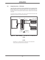
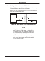
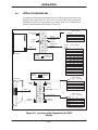
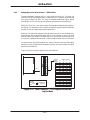
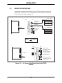
INSTALLATION
3.3
SETTING TI525 DIPSWITCHES
You determine operational parameters for the TI525 by setting switches on two
dipswitches. For the TI525 PLCs, these dipswitches are located on the printed
circuit board (PCB). Refer to Figure 3-3.
Switch position
OFF
Baud
1
ON
9600
2400 OFF
ON
1200
300 OFF
ON
RS-232-C/423
Baud rate
RS-422
Baud rate
2
ON
ON
OFF
OFF
Switch position
DIP 1
Baud
3
ON
9600
2400 OFF
ON
1200
300 OFF
Factory test
must be
set on
4
ON
ON
OFF
OFF
Position
Position not
Selected
Selected
Push Down
OFF
ON
Battery enable
Factory test switches
must be set off
for normatl operation
L- Memory protect on
L-Memory
Download presets
DIP 2
Factory test switches
position does not matter
fro normal use
Figure 3-3
Locations of the Dipswitches for the TI525
Models
3-5
Hardware and Installation User Manual
INSTALLATION
3.3.1
Setting Port Baud Rate — TI525 Models
Figure 3-4 shows the baud rate switch assignments for the communication
ports. Switches 1 and 2 on the first switch bank (DIP 1) set the baud rate for the
RS-232-C/423 port (Port 1). Switches 3 and 4 on DIP 1 set the baud rate for the
RS-422 port (Port 2). Switch position does not matter if a device is not connected
to the port.
You need to set only switches 1 and 2 for PPX:525–1102 and PPX:505–1104
models which have only an RS-232-C/RS-423 port.
OFF
ON
RS-232-C/423
Baud rate
RS-422
Baud rate
DIP 1
Switch position
Baud
1
2
ON
ON
9600
ON
2400 OFF
ON OFF
1200
300 OFF OFF
Switch position
Baud
3
ON
9600
2400 OFF
ON
1200
300 OFF
Position
selected
4
ON
ON
OFF
OFF
Position not
selected
Push down
Figure 3-4
Switch Settings — TI525 RS-232-C/423 and RS-422
Ports
Switches 5, 6, 7, and 8 on the first bank (DIP 1) are reserved for
factory testing and should all be turned ON.
Hardware and Installation User Manual
3-6
INSTALLATION
3.3.2
Selecting Battery Backup — TI525 Models
Switch 1 on the second dipswitch assembly (DIP 2) enables or disables the
battery backup function. With the battery backup enabled, cycling power does
not alter the following information:
RLL program
Timer/counter preset and current values
Drum preset preset and current values
Word I/O values
Variable (V) memory values
Retentive control relay status
States of forced I/O
Scan time
I/O Configuration data
If you power up a TI525 without a good battery installed or with the battery
backup dipswitch turned OFF, the PLC clears memory.
To allow for battery replacement, the TI525 is designed to retain memory for at
least 10 minutes while powered down, even with a bad battery. If the PLC is
powered down without a good battery for longer than 10 minutes, at power-up
the PLC detects whether or not memory is valid. If memory is not valid, then the
PLC clears memory upon power-up.
Refer to Figure 3-5. Turn switch 1 ON to enable the battery backup. Turn switch
1 OFF to disable battery backup.
OFF
Battery disable
ON
Battery enable
DIP 2
Position
selected
Figure 3-5
Position not
selected
Push down
Switch Settings — TI525 Battery Backup
Switches 2, 3, 6, 7, and 8 on DIP 2 are reserved for factory
testing. Switches 2 and 3 should be turned off. The position of
switches 6, 7, and 8 do not matter for normal operation.
3-7
Hardware and Installation User Manual
INSTALLATION
3.3.3
Selecting Ladder Memory Protection — TI525 Models
Switch 4 on DIP 2 prevents modifications to the RLL program in ladder memory.
Your programming unit refers to this switch as a keylock.
Refer to Figure 3-6. Turn switch 4 ON to prohibit changes to the program. Turn
switch 4 OFF to permit program editing.
OFF
ON
L-Memory
protect on
L-Memory
protect off
DIP 2
Position
Selected
Figure 3-6
Position not
Selected
Push Down
Switch Settings — TI525 L-Memory Protection
Turning the L-memory protect switch on does not prevent
forcing I/O, changing variable memory, or switching the PLC
from PROGRAM to RUN mode. These actions may be initiated
with a programming device connected to the PLC, or a special
function I/O module designed for this type of interface to the
PLC, e.g., a Network Interface Module.
The RLL can also be changed through a special function
module, even when the memory protection is enabled with the
keylock. Do not depend upon this switch to prevent personnel
from interrupting your process.
Hardware and Installation User Manual
3-8
INSTALLATION
3.3.4
Downloading Preset Constants — TI525 Models
The drum and timer/counter instructions have reserved sections of memory
where preset variables are stored. These variables may be changed with an
operator interface, such as a TCAM or VPU, or with an RLL instruction,
without altering their value in the RLL program. If you cycle power or execute
AUX Function 10 while the battery is enabled, switch 5 on DIP 2 determines
whether the changed values in preset memory are retained or the original
values are downloaded from the RLL program. If the battery is dead, low, or
disabled, the preset values are always downloaded from the RLL program in an
EPROM/EEPROM, if one is installed.
Refer to Figure 3-7. Turn switch 5 ON to have values downloaded from the RLL
program. Turn switch 5 on DIP 2 OFF to have preset values retained.
OFF
Retain
presets
Download
presets
DIP 2
Figure 3-7
ON
Position
selected
Position not
selected
Push down
Switch Settings — TI525 Download/Retain Presets
Executing AUX Function 12 (PLC Complete Restart) with your
programming device causes the presets to be downloaded from
the RLL program, regardless of the state of this dipswitch.
3-9
Hardware and Installation User Manual
INSTALLATION
3.4
SETTING TI535 DIPSWITCHES
You determine operational parameters for the TI535 by setting switches on two
dipswitch block assemblies. For the TI535 PLCs, this is done with one block of
dipswitches located on the printed circuit board (PCB) and a second block
located inside the battery door. Refer to Figure 3-8.
OFF
ON
Switch position
I/O Type
2
3
Factory test
set off
Status
Test
Test
No status
I/O type
and factory test
Retain
presets
Download
presets
Highest base
address
DIP 1
Front bezel
Position
selected
Push down
Position
Selected
Position not
selected
Position not
Selected
Highest
base
address
0
1
2
3
4
5
6
7
8
9
10
11
12
13
14
15
PUSH LEFT
Battery
enable
DIP 2
PUSH RIGHT
RS-422
Baud rate
ON
ON
ON
ON
ON
ON
ON
ON
OFF
OFF
.
OFF
OFF
OFF
OFF
OFF
OFF
R
L
R
L
*
R
R
L
L
*
R
R
R
R
L
R
L
R
L
*
R
R
L
L
*
R
R
R
R
L
Position does not matter
Locations of the Dipswitches for TI535
Models
3-10
ON
ON
ON
ON
OFF
OFF
OFF
OFF
ON
ON
ON
ON
OFF
OFF
OFF
OFF
Position does not matter
300
1200
2400
9600
19200
L-Memory
Protect off
*
Hardware and Installation User Manual
ON
ON
OFF
OFF
ON
ON
OFF
OFF
ON
ON
OFF
OFF
ON
ON
OFF
OFF
8
Switch position
R = Right
L = Left
Baud
5
6
7
RS-232-C/423
Baud rate
Figure 3-8
ON
OFF
ON
OFF
ON
OFF
ON
OFF
ON
OFF
ON
OFF
ON
OFF
ON
OFF
300
1200
2400
9600
19200
Battery
disable
*
L Memory
Protect on
Switch position
5
6
7
ON
OFF
ON
OFF
Switch position
L = Left
R = Right
Baud
2
3
4
Push left or right
Front bezel
ON
ON
OFF
OFF
INSTALLATION
Switch 1 on the first dipswitch (DIP 1) is used for factory testing
and should be turned OFF. Switches 2 and 3 are also reserved
for factory testing and should be turned ON.
3.4.1
Selecting I/O Type — TI535 Models
Some earlier Series 505 I/O modules (manufactured prior to January 1, 1988) do
not report module status to the CPU. Modules built after this date do report
status. Complete the following steps to determine which type of I/O you have.
1. Disconnect all user-supplied power from the base.
2. Remove the I/O module.
3. Find the serial number label on the inside of the front bezel. If you have
a number greater than XXXX8801XXXXXX, you have a module that
reports status. If you have a serial number less than or equal to
XXXX8712XXXXXX, you have a module that does not report status.
Switches 2 and 3 on DIP 1 determine whether the CPU expects the status to be
reported.
If the switches are both ON, the CPU expects the status to be reported. If you
install I/O modules that do not report status, the CPU reports an I/O mismatch
and I/O failure.
If the switches are both OFF, the CPU does not expect the status to be reported.
When both switches are off, you can use either type of I/O.
When the switches are mixed (ON/OFF or OFF/ON), the CPU is set for factory
tests.
3-11
Hardware and Installation User Manual
INSTALLATION
3.4.2
Downloading Preset Constants — TI535 Models
The drum and timer/counter instructions have reserved sections of memory
where preset variables are stored. These variables may be changed with an
operator interface, such as a TCAM or VPU, without altering their value in the
RLL program. If you cycle power or execute AUX Function 10 or 11 while the
battery is enabled, switch 4 on DIP 1 determines whether values in preset
memory are retained or downloaded from the RLL program. If the battery is
dead, low, or disabled, the preset values are always downloaded from the RLL
program in an EPROM/EEPROM, if one is installed.
Refer to Figure 3-9. Turn switch 4 ON to have values downloaded from the RLL
program. Turn switch 4 OFF to have preset values retained.
OFF
Retain
presets
ON
Download
presets
DIP 1
Position
selected
Push down
Figure 3-9
Position not
selected
Switch Settings — TI535 Download/Retain Presets
Executing AUX Function 12 (PLC Complete Restart) with your
programming device causes the presets to be downloaded from
the RLL program, regardless of the state of this dipswitch.
Hardware and Installation User Manual
3-12
INSTALLATION
3.4.3
Setting Highest I/O Base Number — TI535 Models
The base assembly holding the PLC also holds the local I/O. The local I/O
consists of the first two logical bases, numbered 0 and 1. A logical base is defined
as a group of eight I/O slots. As many as fourteen additional logical bases,
numbered from 2 to 15, may be connected to the system as distributed I/O.
Switches 5–8 on DIP 1 are used to select the highest-numbered logical base in
the system. For example, if your system consists of 5 logical bases numbered 0
through 5, then the dipswitches should be set for 5.
Switches 5–8 reduce I/O update time by preventing the PLC from attempting to
communicate with distributed bases that are not present or which you may
have shut down. Although it increases scan time, you can set the switches for 15
if you prefer, regardless of the actual number of logical bases that are connected.
You may connect Series 500 bases to your system. Number the Series 500 logical
bases just as you would Series 505 bases; however, the total number of logical
bases cannot exceed 16.
Figure 3-10 lists the switch positions for each address.
OFF
ON
DIP 1
Position
selected
Push down
Figure 3-10
Position not
selected
Highest
base
address
0
1
2
3
4
5
6
7
8
9
10
11
12
13
14
15
5
ON
OFF
ON
OFF
ON
OFF
ON
OFF
ON
OFF
ON
OFF
ON
OFF
ON
OFF
Switch position
6
7
8
ON
ON
OFF
OFF
ON
ON
OFF
OFF
ON
ON
OFF
OFF
ON
ON
OFF
OFF
ON
ON
ON
ON
OFF
OFF
OFF
OFF
ON
ON
ON
ON
OFF
OFF
OFF
OFF
ON
ON
ON
ON
ON
ON
ON
ON
OFF
OFF
.
OFF
OFF
OFF
OFF
OFF
OFF
Switch Settings — TI535 Highest-Numbered
Logical Base
3-13
Hardware and Installation User Manual
INSTALLATION
3.4.4
Selecting Battery Backup — TI535 Models
Switch 1 on the second dipswitch assembly (DIP 2) enables or disables the
battery backup function. With the battery backup enabled, cycling power does
not alter the following information:
RLL program
Timer/counter preset and current values
Drum preset preset and current values
Word I/O values
Variable (V) memory values
Retentive control relay status
States of forced I/O
Scan time
I/O Configuration data
If you power up a TI535 with the battery backup dipswitch turned OFF and
have not installed an EPROM/EEPROM, the PLC clears memory.
If you are powering up a TI535 for the first time, turn off the
battery backup and do not install a programmed
EPROM/EEPROM. This ensures that the PLC is properly
initialized.
Refer to Figure 3-11. Push Switch 1 LEFT to enable the battery backup. Push
switch 1 RIGHT to disable battery backup.
PUSH LEFT
Battery
enable
PUSH RIGHT
Battery
disable
DIP 2
Figure 3-11
Hardware and Installation User Manual
Switch Settings — TI535 Battery Backup
3-14
INSTALLATION
3.4.5
Setting Communication Port Baud Rate —TI535 Models
Figure 3-12 shows the baud rate switch assignments for the communication
ports. Switches 2–4 on the second dipswitch assembly (DIP 2) set the baud rate
for the RS-422 9-pin port (Port 2). Switches 5–7 set the baud rate for the
RS-232-C/423 25-pin port (Port 1). Switch position does not matter if a device is
not to be connected to the port.
PUSH
LEFT
DIP 2
PUSH
RIGHT
RS–422
Baud rate
RS–232–C/423
Baud rate
Switch position
L = Left
R = Right
Baud
2
3
4
300 R
R
R
R
1200 L
R
L
2400 R
R
L
9600 L
R
*
*
19200
L
* Position does not matter
Switch position
L = Left
R = Right
Baud
5
6
7
300 R
R
R
R
1200 L
R
L
2400 R
R
L
9600 L
R
*
*
19200
L
* Position does not matter
Figure 3-12
Switch Settings — TI535 RS-232-C/RS-423 and
RS-422 Ports
3-15
Hardware and Installation User Manual
INSTALLATION
3.4.6
Selecting Ladder Memory Protection — TI535 Models
Switch 8 on DIP 2 prevents changes to the RLL program in ladder memory. Your
programming unit refers to this switch as a keylock.
Refer to Figure 3-13. Push switch 8 LEFT to prohibit changes to the program.
Push switch 8 RIGHT to permit program editing.
PUSH
LEFT
PUSH
RIGHT
Position
selected
DIP 2
Position not
selected
Push Left or Right
L-Memory
protect off
L-Memory
protect on
Figure 3-13
Switch Settings — TI535 L–Memory Protection
Turning the L-memory protect switch on does not prevent
forcing I/O, changing variable memory, or switching the PLC
from PROGRAM to RUN mode. These actions may be made by a
programming device connected to the PLC, or a special function
I/O module designed for this type of interface to the PLC, e.g., a
Network Interface Module.
The RLL can also be changed through a special function
module, even when the memory protection is enabled with the
keylock. Do not depend upon this switch to prevent personnel
from interrupting your process.
Hardware and Installation User Manual
3-16
INSTALLATION
3.5
INSTALLING THE BATTERY
The TI525/TI535 PLCs are shipped with a lithium battery already installed.
This battery has a minimum storage lifetime of three years and a minimum
backup lifetime of six months (0to 60C). Follow the steps listed below to
replace the battery.
3.5.1
Model TI525 Battery Installation
The TI525 is capable of preserving system memory for at least ten minutes after
the battery and power have been disconnected. Complete the battery
replacement within this period if you wish to save information.
1. Disable all user-supplied power to the base.
2. Remove the PLC from the base. Do not touch the components on the
printed circuit board or short any etch lines or pins as this may
disrupt system memory. Do not place the PLC on a conductive
surface.
3. Check the battery backup switch (DIP 2, switch 1). If it is off and you
wish to retain system memory, turn the switch on.
4. Remove the battery from the clip and disconnect the leads.
5. The new battery should be a 3.0 VDC UL Recognized lithium battery
(PPX:2587678–8005). Connect the red wire to the positive pole and
the black wire to the negative pole of the new battery. Then insert
the new battery into the battery holder.
6. Insert the PLC into the base, enable power, and verify that the BATT
GOOD LED comes on.
3-17
Hardware and Installation User Manual
INSTALLATION
3.5.2
Model TI535 Battery Installation
Take the following steps to replace the battery.
1. Ensure that the power to the PLC is on. Replacing the
battery with power off will result in memory loss.
2. Open the battery door as shown in Figure 3-14.
Battery
Figure 3-14
Battery Location for TI535 Models
3. Remove the battery from the compartment and disconnect the leads.
4. Attach the leads to the new battery (3.0 VDC UL Recognized lithium
battery (PPX:2587678–8005). Connect the red wire to the positive
pole and the black wire to the negative pole. Push the new battery
and leads back into the compartment.
5. Set the battery dipswitch ON (DIP 2, switch 1) if you wish to enable
battery backup. The BATT GOOD indicator should light.
6. Close the battery door.
Hardware and Installation User Manual
3-18