1
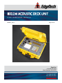
8011M ACOUSTIC DECK UNIT
USER HARDWARE MANUAL
0004811_REV_C
August 2015
EdgeTech
4 Little Brook Road
West Wareham, MA 02576
Tel: (508) 291-0057
Fax: (508) 291-2491
www.EdgeTech.com
ii
The information, figures, and specifications in this manual are proprietary and are issued in strict
confidence on condition that they not be copied, reprinted, or disclosed to a third party, either wholly or
in part, without the prior, written consent of EdgeTech. Any reproduction of EdgeTech supplied software
or file sharing is strictly prohibited.
©Copyright 2015 by EdgeTech. All rights reserved.
Storm Case™ is a trademark of Pelican.
8011M ACOUSTIC DECK UNIT
0004811_REV_C
iii
ATTENTION – READ THIS FIRST!
All personnel involved with the installation, operation, or maintenance of the equipment described in this
manual should read and understand the warnings and cautions provided below.
CAUTION!
This equipment contains devices that are extremely sensitive to static
electricity. Therefore, extreme care should be taken when handling them.
Normal handling precautions involve the use of anti-static protection
materials and grounding straps for personnel.
WARNING!
High Voltage may be present in all parts of the system. Therefore, use
caution when the electronics are removed from their containers for
servicing.
CAUTION!
Operation with improper line voltage may cause serious damage to the
equipment. Always ensure that the proper line voltage is used.
iv
HARDWARE VARIATIONS AND COMPATIBILITY
The 8011M Acoustic Deck Unit contains both standard and proprietary hardware. At times, EdgeTech may
change the standard components due to their availability or performance improvements. Although the
component manufacturers—along with their models and styles—may change from unit to unit,
replacement parts will generally be interchangeable.
EdgeTech will make every effort to see that replacement components are interchangeable and use the
same software drivers (if applicable). At times, however, direct replacements may not exist. When this
happens, EdgeTech will provide the necessary drivers with the replacement part, if applicable.
EdgeTech may also change certain hardware per customer requirements. Therefore, portions of this
manual, such as parts lists and test features, are subject to change. These sections should be used for
reference only. When changes are made that affect system operation, they will be explicitly noted. Also,
some options and features may not be active in the customer’s unit at time of delivery. Upgrades will be
made available when these features are implemented.
Contact EdgeTech Customer Service with any questions relating to compatibility.
8011M ACOUSTIC DECK UNIT
0004811_REV_C
v
ABOUT THIS DOCUMENT
We, the employees at EdgeTech, would like to thank you for purchasing 8011M. At EdgeTech, it is our
policy to provide high-quality, cost-effective products and support services that meet or exceed your
requirements. We also strive to deliver them on-time, and to continuously look for ways to improve them.
We take pride in the products we manufacture, and want you to be entirely satisfied with your equipment.
Purpose of this Manual
The purpose of this manual is to provide the user with information on the setup and use of EdgeTech’s
8011M. Although this manual encompasses the latest operational features of the unit, some features may
be periodically upgraded. Therefore, the information in this manual is subject to change and should be
used for reference only.
Liability
EdgeTech has made every effort to document the 8011M in this manual accurately and completely.
However, EdgeTech assumes no liability for errors or for any damages that result from the use of this
manual or the equipment it documents. EdgeTech reserves the right to upgrade features of this
equipment, and to make changes to this manual, without notice at any time.
Warnings, Cautions, and Notes
Where applicable, warnings, cautions, and notes are provided in this manual as follows:
WARNING!
Identifies a potential hazard that could cause injury or death.
CAUTION!
Identifies a potential hazard that could damage equipment or data.
NOTE: Recommendations or general information that is particular to
the material being presented.
vi
WARRANTY STATEMENT
All equipment manufactured by EdgeTech is warranted against defective components and workmanship
for a period of one year after shipment. Warranty repair will be done by EdgeTech free of charge.
Shipping costs are to be borne by the customer. Malfunction due to improper use is not covered in the
warranty, and EdgeTech disclaims any liability for consequential damage resulting from defects in the
performance of the equipment. No product is warranted as being fit for a particular purpose, and there is
no warranty of merchantability. This warranty applies only if:
i.
The items are used solely under the operating conditions and in the manner recommended in
Seller's instruction manual, specifications, or other literature.
ii.
The items have not been misused or abused in any manner, nor have repairs been attempted
thereon without the approval of EdgeTech Customer Service.
iii.
Written notice of the failure within the warranty period is forwarded to Seller and the directions
received for properly identifying items returned under warranty are followed.
iv.
The return notice authorizes Seller to examine and disassemble returned products to the extent
Seller deems necessary to ascertain the cause for failure.
The warranties expressed herein are exclusive. There are no other warranties, either expressed or implied,
beyond those set forth herein, and Seller does not assume any other obligation or liability in connection
with the sale or use of said products. Any product or service repaired under this warranty shall be
warranted for the remaining portion of the original warranty period only.
Equipment not manufactured by EdgeTech is supported only to the extent of the original manufacturer's
warranties.
8011M ACOUSTIC DECK UNIT
0004811_REV_C
vii
RETURNED MATERIAL AU THORIZATION
Prior to returning any equipment to EdgeTech, a Returned Material Authorization (RMA) number must be
obtained. The RMA will help us identify your equipment when it arrives at our receiving dock and track
the equipment while it is at our facility. The material should be shipped to the address provided in the
EdgeTech Customer Service section. Please refer to the RMA number on all documents and
correspondences as well.
All returned materials must be shipped prepaid. Freight collect shipments will not be accepted. EdgeTech
will pay freight charges on materials going back to the customer after they have been evaluated and/or
repaired.
CAUTION!
If your product is a portable topside, never attempt to it in its Storm
CaseTM alone. Although rugged, these cases are not intended to be used
as shipping containers, and the delicate internal components could be
damaged if used in this manner.
The following steps apply only to material being returned from outside the Continental United States.
Follow them carefully to prevent delays and additional costs.
1. All shipments must be accompanied by three copies of your proforma invoice, showing the value
of the material and the reason for its return. If the reason is for repair, it must be clearly stated in
order to move through customs quickly and without duties being charged. Whenever possible,
please send copies of original export shipping documents with the consignment.
2. If the value of the equipment is over $1000, the following Shipper's oath must be sent with the
invoice. This oath can be typed on the invoice, or on a separate letterhead:
"I, ______________________________, declare that the articles herein specified are the
growth, produce, or manufacture of the United States; that they were exported from the
United States from the port of _____________________, on or about _______________;
that they are returned without having been advanced in value or improved in condition
by any process of manufacture or any other means; and that no drawback, or allowance
has been paid or admitted hereof."
Signed ______________________________
viii
3. If there is more than one item per consignment, a packing list must accompany the shipment. It
is acceptable to combine the proforma invoice and packing list as long as the contents of each
carton are clearly numbered and identified on the invoice.
4. Small items can be shipped prepaid directly to EdgeTech by FedEx, DHL, UPS, Airborne, etc.
5. If the equipment is the property of EdgeTech (formerly EG&G Marine Instruments Division),
please insure for full value.
6. Fax one invoice, packing list, and a copy of the airway bill to EdgeTech upon shipment.
8011M ACOUSTIC DECK UNIT
0004811_REV_C
ix
CUSTOMER SERVICE
Customer service personnel at EdgeTech are always eager to hear from users of our products. Your
feedback is welcome, and is a valuable source of information which we use to continually improve these
products. Therefore we encourage you to contact EdgeTech Customer Service to offer any suggestions or
to request technical support:
NOTE:
Please have your system Serial Number available when
contacting Customer Service.
E-mail:
[email protected]
Mail:
4 Little Brook Road
West Wareham, MA 02576
Telephone:
(508) 291-0057
Facsimile:
(508) 291-2491
24-Hour Emergency
Technical Support Line:
(508) 942-8043
For more information please go to www.EdgeTech.com.
x
COMPANY BACKGROUND
EdgeTech (formerly EG&G Marine Instruments) traces its history in underwater data acquisition and
processing back to 1966. EdgeTech has designed, developed, and manufactured products, instruments,
and systems—for the acquisition of underwater data, including marine, estuarine, and coastal
applications—for over 45 years.
The company has responded to the needs of the scientific, Naval, and offshore communities by providing
equipment—such as sub-bottom profilers, side scan sonar, acoustic releases, USBL positioning systems,
and bathymetric systems—that have become standards in the industry.
EdgeTech has also consistently anticipated and responded to future needs through an active research and
development program. Current efforts are focused on the application of cutting-edge CHIRP and acoustic
technology.
8011M ACOUSTIC DECK UNIT
0004811_REV_C
xi
TABLE OF CONTENTS
ATTENTION – READ THIS FIRST! ......................................................................................................... iii
HARDWARE VARIATIONS AND COMPATIBILITY .................................................................................. iv
ABOUT THIS DOCUMENT .................................................................................................................... v
Purpose of this Manual ............................................................................................................................. v
Liability ...................................................................................................................................................... v
Warnings, Cautions, and Notes................................................................................................................. v
WARRANTY STATEMENT ................................................................................................................... vi
RETURNED MATERIAL AUTHORIZATION ........................................................................................... vii
CUSTOMER SERVICE .......................................................................................................................... ix
COMPANY BACKGROUND .................................................................................................................. x
TABLE OF CONTENTS ......................................................................................................................... xi
LIST OF TABLES ............................................................................................................................... xiii
SECTION 1: OVERVIEW ....................................................................................................................1-1
SECTION 2: SPECIFICATIONS ............................................................................................................2-1
2.1.1.1 Serial Cable Pin Out ............................................................................................................ 2-1
2.1.1.2 Auxiliary Cable Pin Out....................................................................................................... 2-2
SECTION 3: INSTALLATION ...............................................................................................................3-1
SECTION 4: OPERATION...................................................................................................................4-1
4.1 Quick Operation ............................................................................................................................... 4-1
4.1.1 Sending Commands (<CMD>) ................................................................................................... 4-1
4.1.2 Ranging (<RNG>) ....................................................................................................................... 4-2
4.2 Detailed Operating Instructions ....................................................................................................... 4-4
4.2.1 Keypad Descriptions.................................................................................................................. 4-4
4.2.2 Menu (<MENU>) ....................................................................................................................... 4-5
4.2.2.1 Command Setup................................................................................................................. 4-5
4.2.2.2 Range Setup ....................................................................................................................... 4-5
4.2.3 Commands <CMD> ................................................................................................................... 4-6
4.2.4 Ranging <RNG> ......................................................................................................................... 4-7
4.2.5 Serial Port Operations ............................................................................................................... 4-7
xii
4.2.5.1 8011M Host Mode Serial Commands ................................................................................ 4-9
8011M ACOUSTIC DECK UNIT
0004811_REV_C
xiii
LIST OF TABLES
Table 2-1: General Specifications............................................................................................................... 2-1
Table 2-2: 8012A Transducer Specifications .............................................................................................. 2-1
Table 4-1: Keypad Descriptions.................................................................................................................. 4-4
1-1
SECTION 1: OVERVIEW
EdgeTech’s 8011M Acoustic Deck Unit Transceiver is a portable, rugged topside capable of sending and
receiving messages to a deployed system such as one of the acoustic release units offered separately
through EdgeTech.
The 8011M comes standard with a deck unit, set of headphones, spare connector for the auxiliary port,
and a model 8012A transducer for dropping off the side of a vessel to transmit and receive acoustic
signals.
CAUTION!
This deck unit is somewhat splash resistant, but it is not waterproof. It is
not intended to be subjected to seawater, rain, spray, etc.
2-1
SECTION 2: SPECIFICATIONS
The specifications for the 8011M Acoustic Deck Unit are shown in Table 2-1 and Table 2-2:
GENERAL
Frequencies
Transmit
Interrogate and Reply frequencies select 7.5 to 15 kHz
7.5 to 15.0 kHz - Operator adjustable
Receive
7.0 to 15.0 kHz - Operator selectable multiple channels
Transmit source level
192 dB re 1 micro-Pascal at 1 meter - Controllable by operator
Receive sensitivity
-80 dB re 1 micro-Pascal at 1 meter
Transmit pulse width
5 to 30 milliseconds - Operator selectable
Timing accuracy
0.1 millisecond
Range units
Meters and Seconds
Command codes
ORE Offshore, EdgeTech, EG&G, Benthos, Oceano, and MORS
Status receive
Automatic time-line display of acoustic status replies
Beeper
Audio confirmation of received signals
Case
Sealed, portable, polyethylene
Size
40.6 cm x 33 cm x 17.3 cm (16 in. x 13 in. x 6.8 in.)
Weight
7.3 kg (16.0 lbs)
Table 2-1: General Specifications
8012A TRANSDUCER
Acoustic frequency
7.5 to 15 kHz
Beam pattern
Omni-directional in the lower hemisphere
Cable length
67 meters (220 feet)
Weight in air
10 kg (22 lbs) including cable
Size
Diameter 11.4 cm (4.5 in); height 10 cm (4.0 in)
Table 2-2: 8012A Transducer Specifications
2.1.1.1 Serial Cable Pin Out
DB9 pin 2
AMP pin 8
DB9 pin 3
AMP pin 7
DB9 pin 5
AMP pin 2
2-2
SECTION 2: SPECIFICATIONS
2.1.1.2 Auxiliary Cable Pin Out
Pin 1
Ground
Pin 2
TX transmit envelope goes negative at the beginning of the transmit pulse.
Pin 3 Detect goes high on detection of a valid reply pulse this signal is delayed by 11 milliseconds from
the actual detection.
Pin 4 Trigger If the deck unit is in the ranging mode a positive edge in on this pin will initiate a ranging
operation.
The auxiliary port is 5 volt logic.
8011M ACOUSTIC DECK UNIT
0004811_REV_C
3-1
SECTION 3: INSTALLATION
To install the 8011M:
1. Unlatch the cover on the deck unit and open it.
2. Attach the Model 8012A transducer to the TRANSDUCER connector, being sure to screw the
connector down finger tight. (The user may need to apply pressure to the back of the connector
while tightening the locking sleeve).
NOTE: On the early 8011M systems, the transducer connector is a Spirit,
which is the same as used on earlier EG&G, EdgeTech, and ORE Offshore
deck units. Transducers from these systems can be used with the 8011M.
However, if the shorter (32 meter cable) transducer is used, the output
power will be slightly reduced.
On the later 8011M systems, the connector is an Amphenol.
The pin out for the early spirit type connector transducer connectors is as
follows:
1 shield
2 Black low side transducer
3 White high side transducer
4 shorted to 5
5 shorted to 4
Pins 4 & 5 are shorted on the transducer side of the connection so that the
deck unit can sense it.
Pin out for the later Amphenol type connector transducer connectors is as
follows:
A White high side transducer
B Black low side transducer
C shield
D shorted to E
E shorted to D
Pins D & E are shorted on the transducer side of the connection so that
the deck unit can sense it.
3-2
SECTION 3: INSTALLATION
3. Use the supplied Kellems grip to fasten the cable to a suitable anchoring point and lower the
transducer overboard.
NOTE: The Model 8012A is not designed for use on moving vessels.
4. Attach the headphones to the HEADPHONE connector. Be certain that the power available
matches the requirements of the Model 8011M, which is 100 to 230 VAC and 50 to 60 hertz. The
deck unit will auto sense the input voltage, so there is no need to change anything on the deck
unit for input voltages within this range.
5. Once proper voltage is ascertained, plug the instrument into a grounded outlet.
6. The 8011M has an internal rechargeable battery. To fully charge the internal battery, the system
must be plugged in and turned on for 5 hours. The 8011M will run on the internal battery for 4 to
6 hours depending on use.
The battery is being charged or the charge is being maintained whenever it is plugged in and
turned on. When running on the internal battery, the user should always be sure to turn the
backlight off. The backlight severely degrades the charged life of the battery.
The bi-color LED in the front panel displays the battery charge status.
Green
Means that the battery pack is being charged.
Red
Means that the system temperature is too high to continue charging.
7. The 8011M is now ready for operation.
8011M ACOUSTIC DECK UNIT
0004811_REV_C
4-1
SECTION 4: OPERATION
Although full knowledge of the operation of the Model 8011M is recommended to achieve best results,
in many cases, the default operating parameters are adequate for getting the unit operating quickly. This
section provides both a quick operation segment, as well as a full, in-depth usage segment. First-time
users are encouraged to read through both portions entirely and then use the former as a reference during
future deployments.
4.1 Quick Operation
Read SECTION 3: INSTALLATION and set up the 8011M as described before operating the unit.
4.1.1 Sending Commands (<CMD>)
1. If you expect a status reply from the transponder, press <MENU> and select item 2 (range setup)
again select item 2 (reply freq.) use the up down arrows and the <ENTER> key to set the receive
frequency to match the reply frequency of the underwater unit.
2. Press the <CMD> key to send a standard ORE Offshore or EdgeTech command. Then enter the 6
digit command and press <ENT> to send it or <CLR> to modify it if needed. The display will change
to (sending command now) and then (waiting for reply) until a reply is received. If the underwater
unit answers with a status reply then each received pulse will cause a block to be printed on the
display. After the first pulse received the cursor will start to move at one position every .5 seconds.
By counting the positions and noting where the blocks are printed you can determine the status
of the underwater unit. Press <ENT> to exit this mode.
3. To send a command other than the standard ORE Offshore and EdgeTech commands start by
pressing the <MENU> key and selecting item 1 (command setup). Select the type of command
you wish to send. After the type is selected you can press the <CMD> key to enter and send the
command. If the manufacturers command type that you have chosen can contain alphanumeric
characters (Letters) then you enter each character by following the instructions on the display and
press enter to send it. When sending IXSEA type commands hold in the <GRD> key and press <1>
through <6> to enter A through F. The 8011M can send both short and long IXEA/MORS/OCEANO
commands simply enter the 4 or 8 digits and send it. For entering Benthos commands follow the
instructions on the display. Due to the format of Benthos commands the up down arrows on the
key pad must be used to select the frequencies used. "Until the 8011M is powered down and
powered up again the command type will stay at the last one entered. The type of command can
be changed at any time by using the menu.
4. If the command is a guarded command such as a release command or a command requiring extra
security it will be necessary to press and hold in the <GRD> key while pressing <ENT> to transmit
4-2
SECTION 4: OPERATION
the command. The deck unit will inform you if the command is guarded when you try to send it
without holding the guard key pressed.
5. After an ORE type command has been sent and the first reply is received the display will start to
graphically indicate the relative receive times of the status reply pings. Press <ENT> to send
another command or to exit the listening mode.
6. After an IXSEA type command is sent the system will wait for a reply and when the first reply is
received the range will be reported meters and seconds. There is a 4 second lockout after the
range is reported and then the system will wait for a diagnostic reply. If the diagnostic reply is
received the delay time will be reported in milliseconds. See your underwater unit manual for an
explanation of the reported time.
4.1.2 Ranging (<RNG>)
1. Press <Menu> and select item 2 (range setup) and then items 1 and 2 to set the proper interrogate
and reply frequencies. The interrogate frequency is the frequency transmitted from the 8011M
deck unit and the reply frequency is the frequency received by the 8011M deck unit. The correct
frequencies can be found on the configuration sheet supplied with the underwater unit. Note: If
you are testing an underwater unit in air use item 5 to change the minimum range gate to “0”.
This will allow the deck unit to receive the replies in air even though the reported ranges will not
be accurate.
2. Item 3 in the range set up menu is the TAT “Turn Around Time”. This is the internal delay time in
the underwater unit from when it receives the interrogate pulse until it responds. The default is
13 milliseconds. This is the correct value for use with ORE Offshore and EdgeTech equipment. You
will need to change this value when using other manufacturer’s equipment. The value is entered
in milliseconds and the range is 0 to 2000 milliseconds. When calculating ranges this time is
subtracted from the total two way travel time of the acoustic path.
3. Items 4 and 5 in the range set up menu are the upper and lower gates. Any replies received before
the lower range gate or after the upper the upper range gate are ignored. These gates can help
alleviate random noise being treated as a valid reply. The default lower range gate is 50 meters
an underwater unit closer than 50 meters will be ignored by the deck unit. The upper range gate
is 16383 meters any underwater units further away than 16383 meters will be ignored. The
entered values will return to the defaults whenever the deck unit is powered down. The deck unit
will report “no return within range gates” when the max time for the maximum range gate has
passed.
4. Press <RNG> to enter the ranging mode. The frequencies for interrogate and reply being used will
be displayed if changes are required go to the menu.
5. Press <ENT> to commence ranging. The range will be displayed when it is received. The range is
displayed in meters and milliseconds.
8011M ACOUSTIC DECK UNIT
0004811_REV_C
4-3
6. To use the repetitive ranging capability of the 8011M you will first need to enter a repetition rate.
This can be changed under the range set up menu. Select item 6 (more options) and then item 1
(repetitive rate). When in ranging mode if you press the <M/R> key the system will switch
between manual and repeat mode when in the repeat mode the 8011M will start a ranging
operation once every (entered number of seconds). To exit the repeat mode, simply press the
<M/R> key to return to manual ranging. The power up default value for the repeat rate is once
every 8 seconds.
7. The default speed of sound in water used by the 8011M is 1500 meters per second. This can be
changed by using the range set up menu. To enter a speed of sound first press <MENU> select
item 2 (range set up) then item 6 (more options). Item 2 is sound speed select this item and enter
the new sound speed that you wish to use. The range for the speed of sound is 100 to 2000 meters
per second.
8. Slant or horizontal ranging can be used in the 8011M. If the display in item 3 under more options
reads (Switch to Slant range mode) then the system is calculating horizontal ranges, by selecting
item 3 you will switch the system to Slant range mode. If the display in item 3 under more options
reads (Switch to Horizontal range mode) then the system is calculating slant ranges by selecting
item 3 you will switch the system to Horizontal range mode. When you switch to horizontal
ranging you will need to enter the depth of the deck units dunking transducer and the depth of
the underwater unit’s transducer. The power on default mode is slant range.
4-4
SECTION 4: OPERATION
4.2 Detailed Operating Instructions
The following instructions provide a more in-depth description of how to use the system and its functions:
4.2.1 Keypad Descriptions
KEY
NAME
FUNCTION
0-9
CLR
▲
▼
ENT
M/R
Zero – nine
Clear
Up arrow
Down arrow
Enter
Repeat mode
Decimal
Place the digit on display or choose menu item
Clear number from display
Increase the value displayed
Decrease the value displayed
Enter the number on the display
Switch between repetitive and manual ranging
Place a decimal point in number
Ranging
Command
Menu
Guard
Guard
Enter ranging mode
Enter command mode
Enter the menu for set up
Press and hold during guarded commands
Also used as “shift” for entering letters
.
RNG
CMD
MENU
GRD
GRD
Table 4-1: Keypad Descriptions
There are 5 function keys across the top of the keypad. These are used to change different levels in the
deck unit. From left to right they are:
Transmit power out
(Picture of a transducer with an (O) in it). The output power can be
adjusted from 0 to 9 with zero being the lowest output level.
Receive sensitivity
(Picture of a transducer with an (I) in it). The receive sensitivity can be
adjusted from 0 to 9 with 0 being the least sensitive.
Display contrast
(Picture of an eye) Going up or down will change the contrast on the
display 0 to 9.
Headphone volume
(picture of a set of headphones) Range is 0 to 9 with 9 being the
loudest.
Backlight
(picture of a light bulb) Pressing this will toggle the backlight on and off.
8011M ACOUSTIC DECK UNIT
0004811_REV_C
4-5
4.2.2 Menu (<MENU>)
The <MENU> key is used to access the setup capabilities of the Model 8011M. In general when an item is
selected in a menu either that item is chosen or a value will need to be entered or adjusted up and down.
To select an item press the number key associated with that parameter. For example, when <MENU> is
selected, one can change the system set up by pressing the <3> key.
Pressing a key will either bring up a sub-menu or allow changing a value by entering a number or toggling
through choices. Once the value is entered and <ENT> is pressed, the menu moves back up one level.
There are three main items: <1> Command setup, <2> Range setup and <3> System setup.
4.2.2.1 Command Setup
In the command setup menu there are four choices:
1. EdgeTech/ORE which will send the standard 6 digit BACS commands sometimes referred to as
Binary Acoustic Command System.
2. Benthos which will transmit the standard Benthos rate encoded type commands.
3. MORS / IXSEA will transmit the bit encoded commands which are the same for OCEANO.
4.2.2.2 Range Setup
In range setup there are six choices:
1. Interrogate frequency allows the user to change the frequency that is transmitted by the 8011M
to the underwater unit. The value can be from 7.5 kilohertz to 15.0 kilohertz in 500 hertz steps.
2. Reply frequency is used for setting the frequency that the 8011M will receive as a valid reply from
the underwater unit. The value can be from 7.0 kilohertz to 15.0 kilohertz in 500 hertz steps.
3. Turnaround time is the internal delay in the particular underwater unit being used for the ranging
operation. This is the time from when pulse arrives at the underwater unit to when the
underwater unit actually transmits in response. This time is subtracted from the total round trip
travel time when calculating ranges. The turnaround time can be set from 0 to 1 second in 1
millisecond increments.
4. Upper range gate is used to set the maximum allowable range during ranging operations. Any
replies received after the upper range limit is reached will be ignored.
5. Lower range gate is used to set the shortest allowable range. Any reply received before the lower
range gate is ignored. The range gates allow the user to lockout random noise and or other
transponders in the area by only allowing replies from within a selected area.
6. More options is selected to enter a sub menu containing more settings.
4-6
SECTION 4: OPERATION
In the “more options” menu there are three items:
o
o
o
Repetitive rate is for setting the rate at which the system will start each ranging operation
in repeat mode. Each increment of this value is one second.
Sound speed is for changing the value used for “speed of sound” in the range calculation.
The default speed of sound used is 1500 meters per second. The allowable range is 100
to 2000 meters per second.
Slant / Horizontal range mode is used to switch between slant and horizontal ranging
mode.
4.2.3 Commands <CMD>
The command mode is used to transmit commands to underwater equipment. ORE Offshore and
EdgeTech commands are supported as well as other manufacturer’s commands. In general, a command
is sent as follows: press <CMD> to enter command mode. The command can then be entered. Enter the
command code and press <ENT> key. Guarded commands require that the <GRD> key be pressed at the
same time as the <ENT> key. If you wish to send another manufacturers command then it must be
selected in the menus before entering the command mode.
After the command is transmitted and the receive lockout time has passed, the model 8011M goes into
the “listen” mode where it waits for replies from the underwater equipment. Upon receipt of the first
detection, the display becomes a time line indicating the detector activity. The number of dots per time
intervals is (0.5 seconds) the detections of the reply pulses are counted and displayed at the current
character position.
No replies are indicated by a dot at the particular character position. Depending on the arrival time of a
reply there may be 2 blocks displayed for 1 reply this should not impair deciphering the status since the
pulses are separated by at least 1 second. This display aids in deciphering the reply message from the
underwater unit. To determine the status of the underwater unit refer to the manual for that particular
system. Status is usually reported by a string of pulses at either a 1 per second or 1 per 2 seconds and
either 7 to 8 pulse or 14 to 15 pulses long. Pressing <ENT> will exit the listening mode.
EdgeTech acoustic equipment uses a 16 bit FKS code. The actual code that the operator enters is a sixdigit code. The first digit encodes the two frequencies used for transmission and must be between 1 and
6 inclusive. The last five digits represent the specific binary code transmitted, less a final parity bit, and
must be between 0 and 7 inclusive. Each underwater unit is supplied with a configuration sheet which
shows the commands and the frequencies used during ranging for that particular system.
8011M ACOUSTIC DECK UNIT
0004811_REV_C
4-7
4.2.4 Ranging <RNG>
The ranging function is use to determine the distance to the underwater unit. Ranging can be done in
Horizontal or Slant mode. In horizontal mode the deck unit calculates the distance between the transducer
of the underwater unit and the transducer of the deck unit after removing the depth of the underwater
unit from the equation. In slant mode the straight line distance to the underwater unit from the deck
unit’s transducer is calculated. In order to use horizontal mode you must know and enter the depth of
each transducer.
To calculate the range the deck unit subtracts the internal delays of the deck unit and the TAT (turnaround
time) from the total two way travel time of interrogate and reply pulses. TAT is the total internal delay of
the underwater unit from the time a valid interrogate pulse arrives at the transducer to the time the reply
pulse is transmitted.
Ranges are reported in meters and milliseconds on the display when they are received. Time is converted
to meters using the speed of sound which can be entered or changed using the menus. The default speed
of sound is 1500 meters per second. When using the repetitive ranging capability you should be sure to
enter a repeat time long enough to allow the reply to come back before the unit sends another interrogate
pulse. If you have trouble ranging try lowering the transducer deeper into the water.
In most cases when ranging problems exist it is because the deck unit does not receive the reply. This can
be caused by ship and surface noise so lowering the transducer will help to avoid this noise. This can also
be caused by thermo-clines reflecting the sound lowering the transducer can help by getting the
transducer below the thermo-cline or at least changing the angle to the thermo-cline. You can also change
the sensitivity setting, if it is too sensitive the deck unit will report random ranges and if it is not sensitive
enough the system will report “no return”.
4.2.5 Serial Port Operations
The model 8011M acoustic deck unit has an RS232 port available to the user. The port can be used to log
activity or to remotely control the deck unit. The 8011M serial port is always in logging mode when it is
not under remote control (host mode).
When logging the 8011M reports range information and any BACS command that has been sent. Each
logged line is followed by a carriage return and line feed. Logged ranges are reported as total time of flight
with the underwater unit’s turnaround time subtracted from it. To determine range you would divide the
time by 2 and then multiply by the speed of sound. The format of logged events is as shown:
RNG: TX = 10.5 RX = 14.0 time = 00.016 Sec.
RNG: TX = 10.5 RX = 14.0 time = 00.015 Sec.
CMD: 341210
4-8
SECTION 4: OPERATION
Host mode is entered by either selecting it as a keypad menu item or by sending a “carriage return / line
feed” thru the serial port. The LCD display will indicate that the 8011M has switched to host mode by
displaying:
HOST MODE: press any key to exit
While in host mode the 8011M will echo all characters sent in the com port. If using a terminal emulation
program be sure to configure it not to locally echo characters. Host mode commands must exactly match
the prescribed format, otherwise they will be rejected.
Serial commands are case sensitive, must include all leading and trailing zeros and must not include
spaces. A pound sign returned from the 8011M indicates a serial command error. All commands that are
accepted in host mode are responded to with an asterisk.
Some examples of host mode operations is:
in10.5 #
Attempt to change the interrogate frequency to 10.5 kHz, rejected due to lower
case characters.
IN10.5 *
Interrogate frequency changed to 10.5 kHz.
RX14.00 *
Receive frequency changed to 14.00kHz.
LG00000 *
Lower range gate set to 0 milliseconds.
UG02000 *
Upper range gate set to 2 seconds.
IN 00026 mS
Interrogate initiated, response received in 26 milliseconds.
IN 00000 mS
Interrogate initiated, no response received with range gates.
CM341256 * $..$...$...$...$...$...$...... # Command 341256 sent, status returned, 7 pings @ 1
second Note the #, this indicates that listening was terminated.
CM341256
BACS command 341256 was terminated during transmission (no asterisk sent)
Ranges displayed while in host mode are reported as total time of flight, it includes the underwater units
turnaround time. To determine range you would subtract the TAT turnaround time for the particular
underwater unit then divide by 2 and multiply the result by the speed of sound. If no response is received
before the upper range gate expires then the range is reported as 00000 milliseconds.
Any BACS acoustic command that is in the process of being transmitted acoustically will be terminated if
any character is sent to the 8011M during transmission. BACS acoustic commands take approximately 9
seconds to transmit. If the command is terminated the 8011M will not return a pound sign, it will send a
carriage return / line feed. After a BACS acoustic command is sent the 8011M will send an asterisk and
then listen for a response from the underwater unit.
8011M ACOUSTIC DECK UNIT
0004811_REV_C
4-9
After the first reply is detected the 8011M will send a question mark and then send either a period or
question mark every 250mS. A question mark indicates a valid reply was detected during that 250mS time
period, a period indicates nothing was detected. The listening mode is terminated by sending a carriage
return / line feed. Host mode can be exited by pressing any key on the 8011M keypad.
4.2.5.1 8011M Host Mode Serial Commands
RXxx.xx
Set receive freq. (reply), xx.xx in kHz (07.50 – 15.25, in 250 Hz steps)
INxx.x
Set transmit freq. (interrogate), xx.x in kHz (07.5 – 15.0, in 250 Hz steps)
IN
Interrogate initiation
RR
Sets the 8011M to return ranges automatically after receipt of “IN“(default)
NR
Do not report ranges automatically
GR
Report last range acquired
SOx
Set output power 0 – 9 (0 is not zero power, it’s the lowest power setting)
SIx
Set receive sensitivity 0 – 9 (9 is most sensitive) (0 is the least sensitive)
UGxxxxx
Set upper range gate 00050 – 21844 milliseconds.
LGxxxxx
Set lower range gate 00000 – 21844 milliseconds. (default 50) set to “0” in when
using in air
CMxxxxxx
Send BACS command xxxxxx, then listens for status report.
4-10
SECTION 4: OPERATION
NOTES:
- Port settings are: 9600,N,8,1
- Serial commands are case sensitive, all are upper case.
- Serial commands require strict attention to format, include all leading
and trailing zeros and do not add spaces.
- An asterisk response from the 8011M (*) indicates command accepted.
- A pound sign response from the 8011M (#) indicates serial command
error.
- Serial port is always in logging mode when not in Host mode.
- Host mode can be entered thru the keypad using the menus or thru the
serial port by pressing enter (carriage return / line feed).
- When listening for command status format is a series question marks
and periods. Question marks indicate a valid reply was detected, periods
indicate no detect. Each character represents a 250mS time period.
NOTE:
For any other questions regarding this system, contact
EdgeTech Customer Service.
8011M ACOUSTIC DECK UNIT
0004811_REV_C